

Page 1

®
Instruction Manual
012-10242A
Dynamics Cart Magnetic Damping
ME-6828
1
2
Included Equipment Part Number
1. Magnetic Damping Accessory ME-6828
2. Keeper plate 648-10173
Required Equipment Part Number
or
PAScar, Plunger Cart, or Collision Cart ME-6950, ME-9430,
Aluminum Dynamics Track ME-6953
For other recommended equipment, see experiments starting on page 3.
or similar
ME-9454
Introduction
Use the Magnetic Damping Accessory to add drag to a PASCO dynamics cart. When the cart moves on an aluminum track, the accessory’s magnets generate eddy currents in the track, which cause an opposing magnetic field.
The resulting drag force is proportional to the cart’s velocity. The amount of damping can be varied by changing
the size of the gap between the magnets and the track.
This manual includes set-up instructions, three experiments (starting on page 3), and sample data (page 13).
Set-up
The Magnetic Damping Accessory attaches to a cart magnetically using the magnets built into the cart’s bumper.
If your cart does not have bumper magnets, install them before using the Magnetic Damping Accessory. (See
instructions included with your cart for bumper magnet installation.)
1. Remove the keeper plate from the Magnetic Damping Accessory and put it aside.
800-772-8700 www.pasco.com
Page 2

Dynamics Cart Magnetic Damping Storage and Safety
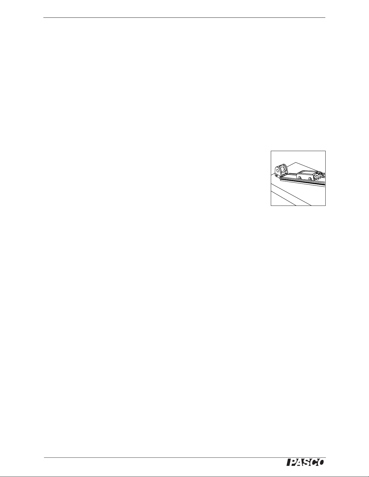
2. Place the Magnetic Damping Accessory on the magnet-equipped end of the cart
as illustrated.
3. Place the cart on an aluminum track.
4. Slide the Magnetic Damping Accessory up or down to adjust the amount of
damping. The magnets should not touch the track.
To set a gap size that can be measured or reproduced, use a stack of cards as a gauge.
Place the cards between the magnets and track as illustrated. Slide the Magnetic
Damping Accessory down until the magnets contact the top card; then remove the
cards. Use calipers to measure the thickness of the stack. For maximum damping, use
a single card.
Storage and Safety
• The Magnetic Damping Accessory is shipped with a keeper plate attached to the
magnets. The keeper protects the magnets and reduces the external magnetic
field. Always store the Magnetic Damping Accessory with the keeper in
place.
• Use caution when replacing the keeper to avoid being pinched or chipping the
magnets.
• Do not remove the magnets from the body of the Magnetic Damping Acces-
sory. If the magnets are accidentally removed, replace them with caution. The
poles of all three magnets should have the same orientation.
• Keep the Magnetic Damping Accessory away from computers and magnetic
recording media.
stack of
cards
Qualitative Demonstrations
The effects of magnetic damping can be surprising. Use these demonstrations illustrate the phenomenon.
• Place a strongly damped cart on a track and ask students to move it by hand.
When the cart is moved quickly, the damping force is easily detected.
• Raise one end of the track by a few centimeters. Set the Magnetic Damping
Accessory for maximum damping and allow the cart to run down the track. With
the track inclined just enough to overcome rolling friction, the cart will creep
very slowly at a constant velocity.
2
®
Page 3
ME-6828 Experiment 1: Damped Oscillation
Experiment 1: Damped Oscillation
Equipment Part Number
Dynamics Cart Magnetic Damping ME-6828
Motion Sensor (optional for Method II) PS-2103A
1
Cart
Aluminum Track
Harmonic Springs
1
1, 2
Adjustable End Stop
IDS Pivot Clamp
1
1
ME-6950, ME-9430, or ME-9454
ME-6953
ME-9803A
ME-8971
ME-9810
or similar
or similar
or similar
or similar
Large Table Clamp ME-9472
90 cm Rod ME-8738
1
These items are components of many PASCO dynamics systems.
2
This experiment works best with a spring, or combination of springs, with a constant between 1.0 N/m and 1.5 N/m.
or similar
Set-up
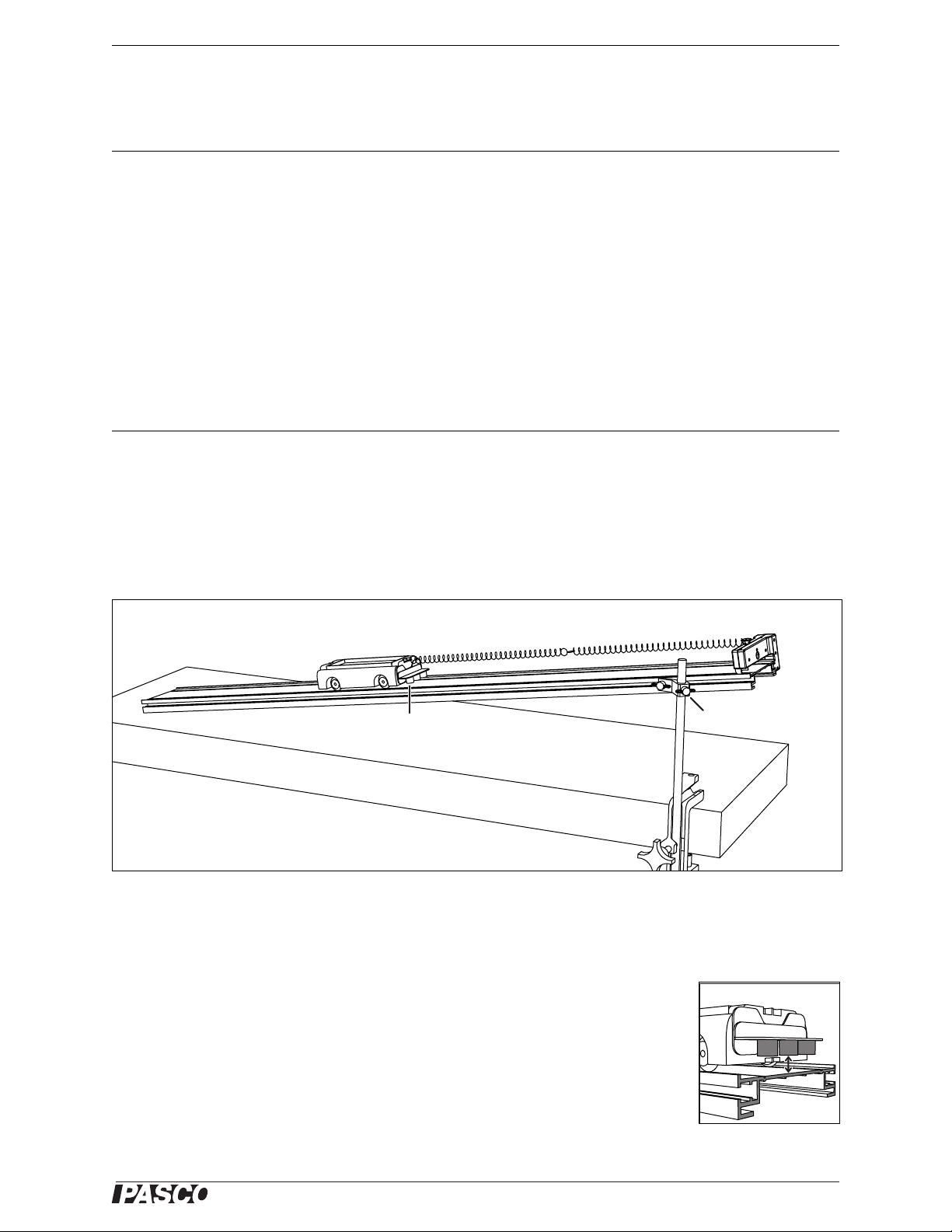
1. Set up the equipment as illustrated. Use two or three weak springs combined
end-to-end.
cart
two or three springs end-to-end
end stop
Magnetic
Damping
Accessory
Experiment set-up for Damped Oscillation
2. Adjust the angle of the track (or the position of the end stop) so that the cart’s
equilibrium position is about 40 cm from the lower end of the track.
Method I (without sensors)
Skip to Method II if you will be using a motion sensor.
1. Place the Magnetic Damping Accessory on the end of the cart with a gap of
10 mm between the magnets and the track.
2. Tap the cart a few times so that it moves to its equilibrium position.
3. Pull the cart up the track and hold it 20.0 cm from equilibrium.
pivot clamp
rod
table clamp
Gap between magnets
and track
®
3
Page 4
Dynamics Cart Magnetic Damping Experiment 1: Damped Oscillation
4. Release the cart.
5. Allow the cart to oscillate. Count (and write down) the number of down-up cycles
that the cart completes before stopping.
6. Repeat steps 3 through 5 with the gap set to 8 mm, 6 mm, 4 mm, and 2 mm, and
with the magnets as close as possible to the track without touching.
Skip to the Questions section on page 4.
Method II (using a motion sensor)
Sensor, Interface, and Software Set-up
For detailed information about setting up your motion sensor, interface, and software, refer to the
instructions supplied with those products.
1. Place a motion sensor at the lower end of the track.
2. Adjust the angle of the track so that the cart’s equilibrium position is about 40 cm
from the sensor.
3. Connect the sensor to your interface.
4. Prepare a graph to display Position versus time.
5. Take some test data and adjust the sensor so that it can measure the cart’s position
up to a distance of about 70 cm. Delete the test data.
Leave the sample rate at the motion sensor’s default of 10 Hz.
Data Collection
1. Place the Magnetic Damping Accessory on the end of the cart with a gap of
10 mm between the magnets and the track.
2. Tap the cart a few times so that it moves to its equilibrium position.
3. Pull the cart up the track and hold it 20.0 cm from equilibrium.
4. Release the cart and start data recording at the same time.
5. Allow the cart to oscillate until it comes to a stop.
6. Stop data recording.
7. Repeat steps 3 through 6 to record data runs with the gap set to 8 mm, 6 mm,
4 mm, and 2 mm. Record a final data run with the magnets as close as possible to
the track without touching.
Motion sensor at end of
track
Question
What is the effect of moving the magnets closer to the track?
4
®
Page 5
ME-6828 Experiment 2: Critical Damping
Experiment 2: Critical Damping
Equipment Part Number
Dynamics Cart Magnetic Damping ME-6828
Stopwatch (for Method I)
ME-1234
or similar
or
Motion Sensor (for Method II)
1, 2
Cart
Aluminum Track
Harmonic Springs
Adjustable End Stop
IDS Pivot Clamp
1
1, 3
1
1
PS-2103A
or similar
ME-6950, ME-9430, or ME-9454
ME-6953
ME-9803A
ME-8971
or similar
or similar
or similar
ME-9810
Large Table Clamp ME-9472
90 cm Rod ME-8738
1
These items are components of many PASCO dynamics systems.
2
Either a plastic or aluminum cart will work; however, the lighter plastic cart allows a relatively greater amount of damping.
3
This experiment requires a spring or combination of springs with constant between 1.0 N/m and 1.5 N/m. If the spring constant is
too high, over damping will not be achievable.
or similar
Set-up
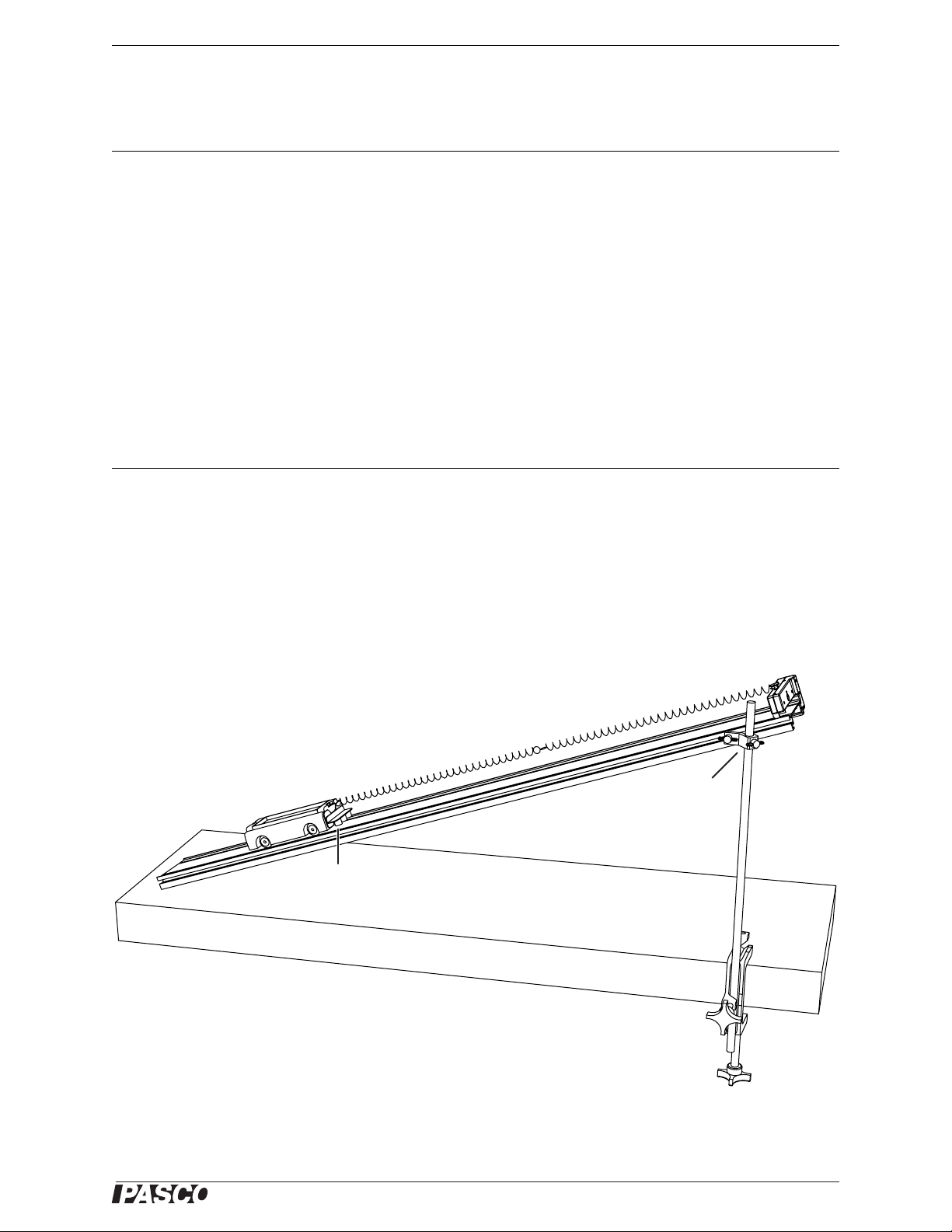
1. Set up the equipment as illustrated. Use two or three weak springs combined
end-to-end.
end stop
two or three springs
end-to-end
cart
Magnetic
Damping
Accessory
Experiment set-up for Critical Damping
2. Adjust the angle of the track (or the position of the end stop) so that the cart’s
equilibrium position is about 20 cm from the lower end of the track.
pivot clamp
rod
table clamp
®
5
Page 6

Dynamics Cart Magnetic Damping Experiment 2: Critical Damping
3. Use tape or a pencil to mark the track about 50 cm above equilibrium.
4. Pull the cart up the track to the mark.
5. Let the cart go and carefully observe it’s movement as it comes to a stop. If the
cart overshoots equilibrium and comes back up the track, it is under-damped. If it
comes to a stop without overshooting, it is either over-damped or critically
damped.
6. Adjust the height of the magnets to reduce or increase the amount of damping.
7. Repeat steps 4 through 6 several times to find the least amount of damping (big-
gest gap) that will make the cart stop without overshooting. This is critical damping.
Method I (using a stopwatch)
Skip to Method II if you will be using a motion sensor.
1. Pull the cart up the track exactly to the mark.
2. Release the cart and start the stopwatch at the same time.
3. Stop the stopwatch when the cart stops.
4. Record the time.
5. Move the magnets up by about 1 mm to make the system under-damped.
6. Repeat steps 1 through 4.
7. Move the magnets down as close to the track as you can get them (without touch-
ing) to make the system over-damped.
8. Repeat steps 1 through 4.
Skip to the Question on page 7.
Method II (using a motion sensor)
Sensor, Interface, and Software Set-up
For detailed information about setting up your motion sensor, interface, and software, refer to the
instructions supplied with those products.
1. Place a motion sensor at the lower end of the track.
2. Connect the sensor to your interface.
3. Set the sampling rate to 50 Hz.
4. Prepare a graph to display Position versus time.
5. Take some test data and adjust the sensor so that it can measure the cart’s position
up to a distance of about 70 cm. Delete the test data.
6
Motion sensor at end of
track
®
Page 7

ME-6828 Experiment 2: Critical Damping
Data Collection
1. Pull the cart up the track exactly to the mark.
2. Release the cart and start data recording at the same time.
3. Wait until the cart stops.
4. Stop data recording.
5. Move the magnets up by about 1 mm to make the system under-damped.
6. Repeat steps 1 through 4.
7. Move the magnets down as close to the track as you can get them (without touch-
ing) to make the system over-damped.
8. Repeat steps 1 through 4.
Question
What type of damping (under, over, or critical) makes the cart stop in the shortest
time?
Further Study: What factors affect critical damping?
You have already discovered that reducing the height of the magnets can change the
system from under-damped to critically damped to over-damped. What other factors
can you adjust to change the system’s damping behavior?
Starting with a critically damped system each time, make the following changes to the
system and observe the result.
• Release the cart from a different position on the track.
• Add about 20 g of mass to the cart.
• Change the angle of the track.
• Change the spring constant (replace or remove one of the springs).
Further Study: Theoretical model
For the theoretical model of the cart’s position as a function of time, we will assume
that the spring is massless and obeys Hooke’s law; that the damping force is proportional to velocity; and that there are no forces acting on the cart other than the spring
force, the damping force, the force of gravity, and the normal force of the track. We
will also set the condition that the initial velocity at time . The
motion of the cart is determined with the following quantities:
v 0() 0= t 0=
x, the position of the cart with at the equilibrium position
x
, the initial position at time
0
x 0=
t 0=
m, the mass of the cart
k, the spring constant ( )
®
F
spring
kx–=
7
Page 8

Dynamics Cart Magnetic Damping Experiment 2: Critical Damping
b, the damping constant ( ) determined by the height of the magnets
ω
γ bm⁄=
0
, the natural frequency of the system in the absence of damping
km⁄=
, a quantity with units of frequency
F
damping
bv–=
If m and k are held constant, then the damping behavior of the system (whether it is
under-, over-, or critically damped) depends on the value of b.
Under damping
For the system to be under-damped, we must have a relatively low value of γ. Let
γ = γ
such that . Then
u
Where .
ωω
2
ω
0
xt() x
2
0
2
γ
4⁄–0>
u
γut–2⁄
e
0
2
γ
4⁄–=
u
γ
u
-------
ωt()cos
2ω
ωt()sin+=
Over damping
For over damping, the value of γ must be higher. Let γ=γ
2
ω
2
γ
0
o
4⁄–0<
. Then
such that
o
1
xt() x
Where .
βγ
0
2
4⁄ω
–=
o
--2
0
γ
γo2⁄β+()t–
o
e
------–
4β
2
x
+=
γ
1
o
---
0
2
------+
4β
e
γo2⁄β–()t–
Critical damping
2
Critical damping occurs at a specific value of γ. Let γ = γ
such that ω
c
2
−γ
/4 = 0.
0
c
Then
γ
t
γct–2⁄
c
xt() x01
=
e
-------+
2
Modeling the cart’s motion
Graph the three equations above and compare them to your actual data. Either measure or estimate your experimental values of x
, m, and k (or ω0) to put into the equa-
0
tions. Estimate values of b for under, over, and critical damping.
8
®
Page 9

ME-6828 Experiment 3: Predicting Terminal Velocity
f
f
Experiment 3: Predicting Terminal Velocity
Equipment Part Number
Dynamics Cart Magnetic Damping ME-6828
Motion Sensor PS-2103A
1
Cart
Aluminum Track
IDS Pivot Clamp
1
1
ME-6950, ME-9430, or ME-9454
ME-6953
ME-9810
or similar
or similar
Large Table Clamp ME-9472
90 cm Rod ME-8738
Angle Indicator
1
These items are components of many PASCO dynamics systems.
2
Or other way to measure track angle
2
ME-9495
or similar
Introduction
In this experiment, you will study the motion of a magnetically damped cart. First,
you will discover the relationship between the velocity and acceleration as it comes to
a stop after being pushed on a level track. Using this relationship, you will predict the
cart’s terminal velocity on a inclined track. Finally, you will test your prediction.
Part I: Acceleration versus Velocity
Theory
The magnetic drag force, f
, is proportional to (and in the opposite direction of)
m
velocity v
(eq. 1)
bv–=
m
where b is a positive constant.
On a level track, assuming no other sources of friction, f
is the only force (along the
m
axis of movement) acting on the cart. Therefore, by Newton’s second law
(eq. 2)
ma=
m
where m is the mass of the cart and a is the acceleration. (Note that f
necessarily constant over time.)
The combination of equations 1 and 2 gives the relationship between a and v
m
(eq. 3)
In a graph of v versus a, the slope will equal .
-----
v
a–=
b
mb⁄–
and a are not
m
®
9
Page 10

Dynamics Cart Magnetic Damping Experiment 3: Predicting Terminal Velocity
Equation 3 assumes that magnetic drag is the only source of friction. A real cart is
also affected by friction that is not proportional velocity, but is constant as long as the
cart is moving. If this additional frictional force is f
, then the net force on the cart is
0
(eq. 4)
F
ma bv– f0–= = for v 0>()
net
and
f
m
0
-----
(eq. 5)
The addition of f
does affect the slope of the v versus a graph, but it does add a ver-
0
v
tical offset (or “Y-intercept’) equal to .
----–=
a–
b
b
b⁄–
f
0
In this part of the experiment, you will use the motion sensor to record v and a as the
cart slows down after you push it on a level track.
Set-up
1. Make the track level.
2. Attach a motion sensor to the left end of the track.
3. Attach the Magnetic Damping Accessory to the cart.
4. If you are using a plastic cart, add about 250 g of mass, so that the total mass is
about 500 g. (Additional mass is not necessary with a metal cart.)
5. Place the cart on the track with the Magnetic Damping Accessory away from the
motion sensor.
6. Adjust the magnets to be about 1 mm above the track. Check to make sure that
the magnets do not touch the track when you push the cart swiftly.
Important: After you have adjusted the magnets, do not readjust them for the remainder of the
experiment.
Experiment set-up for Terminal Velocity, Part I
Sensor, Interface, and Software Set-up
For detailed information about setting up your motion sensor, interface, and software, refer to the
instructions supplied with those products.
1. Connect the sensor to your interface.
2. Prepare a graph (or graphs) to display Position, Velocity, and Acceleration versus
time.
3. Take some test data and adjust the sensor so that it can measure the cart’s position
up to a distance of about 1 m. Delete the test data.
Leave the sample rate at the motion sensor’s default of 10 Hz.
10
®
Page 11

ME-6828 Experiment 3: Predicting Terminal Velocity
Data Collection
You may need to try several times to complete the following steps successfully. If you
do not get it right, delete your data and try again. The recorded data should show the
motion of the cart only after you release it and before it comes to a complete stop.
There should be about 1 s of recorded data. Use one hand to push the cart and the
other hand to start and stop data recording.
1. Using a smooth, sweeping motion, push the cart away from the motion sensor
and release it. Make sure that your hand does not prevent the motion sensor from
detecting the cart.
2. About 0.1 s after releasing the cart, start data recording.
3. Just before the cart stops, stop data recording.
Analysis
1. Create a graph showing velocity (on the vertical axis) versus acceleration (on the
horizontal axis).
2. Apply a linear fit to the data.
According to equation 5, the slope of the best-fit line equals and the Y-intercept equals .
f0b⁄–
mb⁄–
Part II: Predicting Terminal Velocity
Theory
If a cart is allowed to roll down an inclined track, its velocity will increase until the
frictional forces acting against the direction of movement equal the gravitational force
acting in the direction of movement. At that point, the net force on the cart is zero, the
acceleration is zero, and the velocity remains constant. This velocity is known as the
terminal velocity, v
The gravitational force acting on the cart (in the direction of movement) is ,
where g =9.81m/s
(eq. 6)
The values of b and f
Solving equation 6 gives
(eq. 7)
.
T
2
and θ is the angle of incline. At terminal velocity, the net force is
F
0 mg θsin bvTf0––== for vT0>()
net
are the same as they were on the level track.
0
m
-----
v
g θsin
T
b
f
0
----–=
b
mg θsin
Analysis
In Part 1, you found the values of and . Use these values and equation
mb⁄– f0b⁄–
7 to predict the terminal velocity of your cart on a track inclined at θ =3.0°.
At θ =3.0°, v
= _________________, prediction
T
®
11
Page 12

Dynamics Cart Magnetic Damping Experiment 3: Predicting Terminal Velocity
Part III: Measuring Terminal Velocity
Set-up
1. Take the cart off the track and set it aside. (Be careful not to let the Magnetic
Damping Accessory shift on the cart.)
2. Use a table clamp, rod and pivot clamp to raise the left end of the track (with the
motion sensor attached). Adjust the incline to 3.0°.
Experiment set-up for Terminal Velocity, Part III
Data Collection
1. Place the cart back on the track and hold it about 15 cm from the motion sensor
with the magnets away from the sensor.
Note: Before releasing the cart, be prepared to stop it so that the Magnetic Damping Accessory is
not knocked out of position.
2. Start data recording.
3. Release the cart, stop it after it has rolled about 1 m.
4. Stop data recording.
Analysis
From your recorded data, determine the terminal velocity.
At θ =3.0°, v
= _________________, measured
T
Questions
1. How close was your prediction to your measured value of vT? If they were not
exactly equal, what might account for the difference?
2. Would the terminal velocity change if you changed the mass of the cart?
3. Did you have to measure the mass of the cart to predict the terminal velocity?
12
®
Page 13

ME-6828 Sample Data
Sample Data
Experiment 1: Damped Oscillation
Damping
increases as
the magnets
are moved
closer to the
track.
Experiment 2: Critical Damping
Critical damping makes the
cart stop in
the shortest
time.
Note that, due
to static friction, the
under-damped
cart stops at a
slightly different position.
®
13
Page 14

Dynamics Cart Magnetic Damping Sample Data
Experiment 3: Predicting Terminal Velocity
The graph below shows position versus time as the cart is coming to a stop on a level track.
The graph below shows velocity versus acceleration for the cart on the level track.
From the slope and intercept of the best-fit line: and . From these values and equation 7, the predicted terminal velocity is .
mb⁄–0.52 s–= f0b⁄– 0.033 m/s–=
v
0.23 m/s=
T
The graph below shows position versus time for the cart running down a 3° incline. The slope of the linear portion is the measured terminal velocity: .
v
0.2225 m/s=
T
In this case the predicted and measured values differ by about 0.01 m/s, or 4%. The
difference may be due to uncertainty in the values of , , and the angle of
mb⁄ f0b⁄
the inclined track.
The terminal velocity would be different if the cart’s mass were changed. In this
experiment, it is not necessary to know the mass of the cart to predict the terminal
velocity.
14
®
Page 15

ME-6828 Technical Support
Technical Support
For assistance with any PASCO product, contact PASCO at:
Address: PASCO scientific
10101 Foothills Blvd.
Roseville, CA 95747-7100
Phone: 916-786-3800 (worldwide)
800-772-8700 (U.S.)
Fax: (916) 786-7565
Web: www.pasco.com
Email: support@pasco.com
Limited Warranty
For a description of the product warranty, see the PASCO catalog.
Copyright
The PASCO scientific 012-10242A
mission is granted to non-profit educational institutions for reproduction of any part of this manual, providing the reproductions are
used only in their laboratories and classrooms, and are not sold for profit. Reproduction under any other circumstances, without the
written consent of PASCO scientific, is prohibited.
Dynamics Cart Magnetic Damping Instruction Manual
is copyrighted with all rights reserved. Per-
Trademarks
PASCO, PASCO scientific, DataStudio, PASPORT, and ScienceWorkshop are trademarks or registered trademarks of PASCO scientific, in the United States and/or in other countries. All other brands, products, or service names are or may be trademarks or service
marks of, and are used to identify, products or services of, their respective owners. For more information visit www.pasco.com/legal.
®
15
 Loading...