

Page 1
Includes
Teacher's Notes
and
Typical
Experiment Results
PROJECTILE CATCHER
Instruction Manual and
Experiment Guide for
the PASCO scientific
Model ME-6815
ACCESSORY
012-05091E
04/00
CATCHER
Instruction Manual and
Experiments Guide for
PASCO scientific
Model ME-6815
© 1993 PASCO scientific $10.00
PROJECTILE
ACCESSORY
PROJECTILE CATCHER
M
ACCESSORY
E
-6
8
1
5
Page 2
The exclamation point within an equilateral triangle is
intended to alter the user of the presence of important
operating and maintenance (servicing) instructions in
the literature accompanying the appratus.
Page 3

Projectile Catcher Accessory 012-05091E
Table of Contents
Section Page
Copyright, Warranty, and Equipment Return .................................................... iii
Introduction ........................................................................................................ 1
Equipment .......................................................................................................... 1
Projectile Launcher Setup .................................................................................. 2
Ball Catcher Setup ............................................................................................. 3
Experiments
Experiment 1: Ballistic Pendulum ........................................................ 5
Experiment 2: Conservation of Momentum
in an Inelastic Collision ............................................... 11
Demonstration: Inelastic/Elastic Collisions Demonstration ................. 15
Teacher's Guide ............................................................................................... 19
Technical Support ................................................................... Inside Back Cover
ii
Page 4

012-05091E Projectile Catcher Accessory
Copyright, Warranty, and Equipment Return
Please—Feel free to duplicate this manual
subject to the copyright restrictions below.
Copyright Notice
The PASCO scientific ME-6815 Projectile Catcher
Accessory manual is copyrighted and all rights
reserved. However, permission is granted to nonprofit educational institutions for reproduction of any
part of the manual providing the reproductions are
used only for their laboratories and are not sold for
profit. Reproduction under any other circumstances,
without the written consent of PASCO scientific, is
prohibited.
Limited Warranty
PASCO scientific warrants the product to be free from
defects in materials and workmanship for a period of one
year from the date of shipment to the customer. PASCO
will repair or replace at its option any part of the product
which is deemed to be defective in material or workmanship. The warranty does not cover damage to the product
caused by abuse or improper use. Determination of
whether a product failure is the result of a manufacturing
defect or improper use by the customer shall be made
solely by PASCO scientific. Responsibility for the return
of equipment for warranty repair belongs to the customer.
Equipment must be properly packed to prevent damage
and shipped postage or freight prepaid. (Damage caused
by improper packing of the equipment for return shipment
will not be covered by the warranty.) Shipping costs for
returning the equipment after repair will be paid by
PASCO scientific.
Equipment Return
Should the product have to be returned to PASCO
scientific for any reason, notify PASCO scientific by
letter, phone, or fax BEFORE returning the product. Upon
notification, the return authorization and shipping instructions will be promptly issued.
➤ ➤
➤ NOTE: NO EQUIPMENT WILL BE
➤ ➤
ACCEPTED FOR RETURN WITHOUT AN
AUTHORIZATION FROM PASCO.
When returning equipment for repair, the units must be
packed properly. Carriers will not accept responsibility for
damage caused by improper packing. To be certain the
unit will not be damaged in shipment, observe the following rules:
➀ The packing carton must be strong enough for the item
shipped.
➁ Make certain there are at least two inches of packing
material between any point on the apparatus and the
inside walls of the carton.
➂ Make certain that the packing material cannot shift in
the box or become compressed, allowing the
instrument come in contact with the packing carton.
Address: PASCO scientific
10101 Foothills Blvd.
Roseville, CA 95747-7100
Phone: 1-800-772-8700 (toll-free within U.S.)
or
(916) 786-3800
FAX: (916) 786-3292
email: techsupp@pasco.com
web: www.pasco.com
iii
Page 5
012-05091E Projectile Catcher Accessory
Introduction
The PASCO ME-6815 Projectile Catcher Accessory has
three functions:
• A Projectile Launcher is used to shoot a steel ball into
the ball catcher which is mounted on a Dynamics Cart
to show an inelastic collision.
• The steel ball can be bounced off the rubber bumper of
the ball catcher to show an elastic collision between the
ball and the cart.
• The catcher (without cart) can be suspended from
strings and used with the Projectile Launcher as a ballistic pendulum.
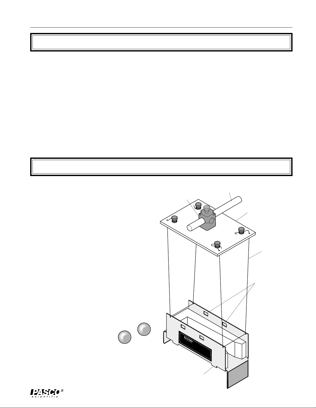
Equipment
The Projectile Catcher Accessory includes the following:
• a ball catcher
• (2) steel projectile balls
• plate assembly from which to hang the catcher
• spool of thread
• Velcro
®
assembly
steel balls
(2)
support rod
(not included)
rod clamp
support plate
thread
slots for
photogate
timing
PROJECTILE CATCHER
M
ACCESSORY
E-6815
ball catcher
1
Page 6

Projectile Catcher Accessory 012-05091E
Projectile Launcher Setup
When using the Projectile Catcher Accessory with a
PASCO ME-6800 or ME-6801 Projectile Launcher,
follow these operation guidelines:
1. Please read the General Operations section of the
Projectile Launcher Manual before using the Pro-
jectile Launcher with the Projectile Catcher Accessory or any other accessory.
Safety goggles are supplied with the Projectile
Launcher and must be worn when operating the
apparatus.
2. The base of the Projectile Launcher must be
clamped to a sturdy table using the clamp of your
choice. When clamping to the table, it is desirable
to have the label side of the launcher even with
one edge of the table so a plumb bob can be used
to locate the position of the muzzle with respect to
the floor.
3. Mount the Projectile Launcher in a horizontal position, using the two lower slots in the Projectile
Launcher base, as shown in Figure 1.
4. Establish the height at which the Projectile
Launcher should be fired and tighten the thumbscrews as required.
WARNING:
Never look down the
front of the barrel of the Projectile
Launcher because it may be loaded.
To check to see if the ball is in the barrel and
whether the Projectile Launcher is cocked, look
at the slots in the side of the barrel. The yellow
indicator seen through the slot indicates the
position of the piston and the ball can be seen
through these slots when it is in the piston.
Wear safety goggles for eye protection.
0
0
WEAR
SAFETY
GLASSES
WHEN IN USE.
clamp
Projectile
Launcher base
Projectile
Launcher
9
8
7
0
6
0
5
0
4
0
3
0
2
0
LONG
MEDIUM
SHORT
RANGE
1
0
0
ME-6800
Yellow Band in Window
RANGE
RANGE
Indicates Range.
Use 25 mm
CAUTION!
CAUTION!
CAUTION!
DO NOT LOOK
DO NOT LOOK
DO NOT LOOK
DOWN BARREL!
DOWN BARREL!
DOWN THE
balls ONLY!
BARREL.
SHORT RANGE
PROJECTILE LAUNCHER
Launch
Position
of Ball
thumbscrews
table
Figure 1: Projectile Launcher Setup
2
Page 7

012-05091E Projectile Catcher Accessory
Ball Catcher Setup
Suspending the Ball Catcher as a
Pendulum
Secure the rod clamp on top of the support plate to a
support rod that is clamped to the table. Cut two
pieces of string, each about two meters long. Thread
one string through the front two holes in the ball
catcher. Thread the other string through the back two
holes in the ball catcher. Refer to the diagram below
on how to attach the string. Thread the ends of the
strings through the holes in the support plate and
secure them, making sure the catcher hangs level.
rod clamp
support rod
(not included)
support plate
thread
Velcro Assembly
You may want to quantify and record the results of
your experiments. To enable the user to measure the
height to which the pendulum swings, a thread must
be connected between the ball catcher and the
launcher. The launcher end slips through a Velcro
assembly, and the amount of extension of the string
shows how far the pendulum swung. See Figure 3.
1. Separate the Velcro hook and loop strips.
2. Cut two square pieces of Velcro loop and one
square piece of Velcro hook.
3. Determine the approximate height at which the
Velcro assembly will be applied. This is determined by the approximate height at which the ball
catcher hangs.
4. Remove the protective covering from the back of
each Velcro square.
5. Arrange the two square pieces of Velcro loop and
one square piece of Velcro hook onto the vertical
plate of the Projectile Launcher base as shown.
PROJECTILE CATCHER
M
ACCESSORY
E
-6815
thumbscrew
support plate
string
Figure 2: Suspending the Ball Catcher
Ball Catcher
assembly
washer
6. Cut one piece of Velcro hook 5 – 6 cm long. Do
not remove the protective backing.
7. Tie a thread to one of the front holes in the ball
catcher.
8. The other end of this thread will pass between the
square piece of Velcro hook (attached to the Projectile Launcher base) and the long piece of Velcro
hook, which should be applied to the three Velcro
squares attached to the Projectile Launcher base.
Projectile
thread
Velcro
hook
ball
catcher
assembly
Figure 3: Velcro Assembly
Launcher base
Velcro
loop
3
Page 8
Projectile Catcher Accessory 012-05091E
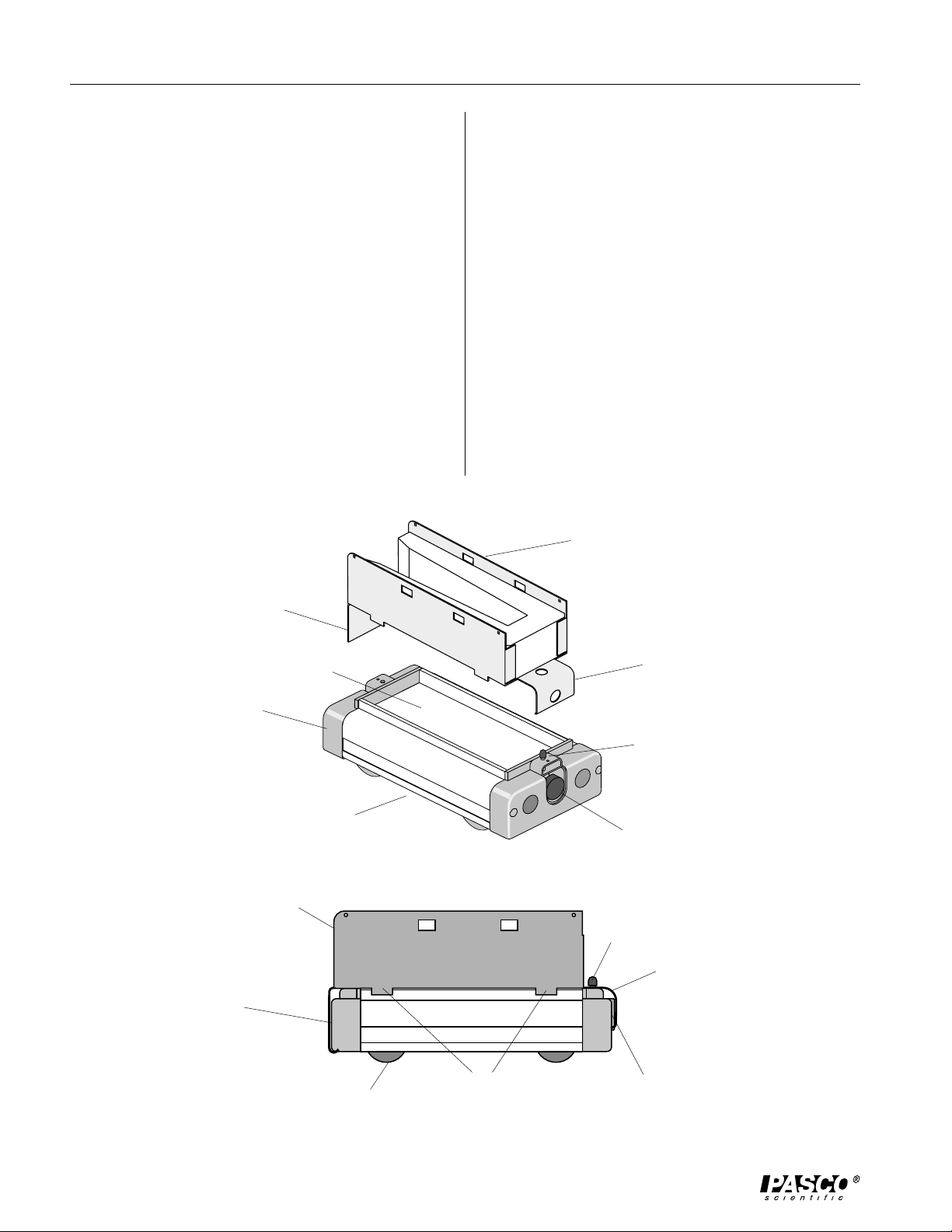
Using the Ball Catcher with the
Dynamics Cart
Some experiments require the ball catcher be attached
to the PASCO ME-9430 Dynamics Cart (Plunger
Cart).
3. Activate the Dynamics Cart’s spring plunger trigger so the cart plunger catches the front lip of the
ball catcher. See Figure 4.
1. Hook the rear lip of the ball catcher under the rear
end cap of the Dynamics Cart. The spring plunger
on the cart must be in the cocked position. (Note
the orientation of the ball catcher. See Figure 4.)
2. Slip the ball catcher onto the Dynamics Cart. A
hole in the ball catcher should slip over the trigger
of the cart. The tabs on the sides of the ball
Catcher fit on the outside of the cart tray.
rear lip
tray
To remove the ball catcher from the Dynamics Cart,
cock the cart plunger by inserting a pen cap or the
eraser end of a pencil into the hole provided on the
front lip of the ball catcher.
ball catcher
front lip
rear end cap
ball catcher
rear lip
trigger
Dynamics Cart
tabs
Dynamics Cart
plunger
trigger
plunger
Figure 4: Mounting the Ball Catcher to the Dynamics Cart
front lip
4
Page 9

012-05091E Projectile Catcher Accessory
CAUTION!
DO NOT LOOK
DOWN BARREL!
CAUTION!
DO NOT LOOK
DOWN BARREL!
CAUTION!
DO NOT LOOK
DOWN THE
BARREL.
LONG
RANGE
MEDIUM
RANGE
SHORT
RANGE
Position
of Ball
Launch
SHORT RANGE
PROJECTILE LAUNCHER
ME-6800
Yellow Band in Window
Indicates Range.
9
0
8
0
7
0
6
0
5
0
4
0
3
0
2
0
1
0
0
WEAR
SAFETY
GLASSES
WHEN IN USE.
Use 25 mm
balls ONLY!
Exp 1: Ballistic Pendulum
EQUIPMENT NEEDED
– Projectile Launcher (ME-6800) -meter stick
– Projectile Catcher Accessory (ME-6815) -white paper
[Velcro must be assembled (See Figure 3)] -carbon paper
– Base and Support Rod (ME-9355) -mass balance
– table clamp
Optional: Photogates and Photogate Bracket
Purpose
The muzzle velocity of the Projectile Launcher can be determined by shooting the ball into
a ballistic pendulum and then measuring the height reached by the pendulum.
Theory
A ball is launched horizontally and embeds in the bob of a pendulum. The pendulum then
swings up to a particular height, h. (See Figure 1.1.)
After Collision
Launcher
9
0
8
0
7
0
6
0
5
0
4
WEAR
0
3
SAFETY
0
2
1
0
GLASSES
0
WHEN IN USE.
Before Collision
Launcher
LONG
MEDIUM
SHORT
Yellow Band in Window
RANGE
RANGE
RANGE
Indicates Range.
Launch
Use 25 mm
CAUTION!
CAUTION!
CAUTION!
DO NOT LOOK
DO NOT LOOK
DO NOT LOOK
Position
DOWN BARREL!
DOWN BARREL!
DOWN THE
of Ball
balls ONLY!
BARREL.
SHORT RANGE
0
ME-6800
PROJECTILE LAUNCHER
v
o
m
b
m
c
Figure 1.1: Conservation of Momentum
Momentum is conserved during the collision, but kinetic energy is not. The momentum
after the collision is equal to the momentum before the collision:
mbvo= mb+ mcv
(1)
mb + m
v
c
where mb is the mass of the ball, vo is the muzzle velocity of the ball, mc is the mass of the
catcher, and v is the velocity of the catcher (and ball) after the collision.
The kinetic energy of the catcher (and ball) after the collision is converted completely to
potential energy at the top of the swing:
1
(2)
mb+ mcv2= mb+ mcgh
2
5
Page 10
Projectile Catcher Accessory 012-05091E
To find the muzzle velocity of the ball,
we begin with the potential energy of the
pendulum at the top of its swing and
work backwards from there. From our
equation for energy conservation (2):
v = o
v =2gh
(3)
Substitute (3) into the equation for
v
h
momentum conservation (1):
mbvo= mb+ mc2gh
+ m
m
b
vo=
m
c
b
2gh
Figure 1.2: Conservation of Energy
For comparison, the initial speed (muzzle velocity) of the ball is determined by shooting
the ball horizontally off the table onto the floor and measuring the vertical and horizontal
distances through which the ball travels.
For a ball shot horizontally off a table with an initial speed, v
, the horizontal distance ("x")
0
traveled by the ball is given by x = v0t, where t is the time the ball is in the air. Air friction
is assumed to be negligible.
1
The vertical distance the ball drops in time t is given by
y =
2
.
gt
2
The initial velocity of the ball can be determined by measuring x and y. The time of flight
of the ball can be found using
t =
and then the muzzle velocity can be found using
2y
g
vo=
x
.
t
Part I: Determining the Initial Velocity of the Ball
Set Up
1. Clamp the Projectile Launcher to a sturdy table (near one end of the table).
2. Adjust the angle of the Projectile Launcher to zero degrees so the ball will be shot off
horizontally, away from the table onto the floor.
Procedure
1. Put the steel ball into the Projectile Launcher and cock it to the long range position. Fire
one shot to locate where the ball hits the floor. At this position, tape a piece of white paper
to the floor. Place a piece of carbon paper (carbon-side down) on top of this paper and tape
it down. When the ball hits the floor, it will leave a mark on the white paper.
2. Fire about ten shots.
6
Page 11

012-05091E Projectile Catcher Accessory
3. Measure the vertical distance from the bottom of the ball as it leaves the barrel (this position is marked on the side of the barrel) to the floor. Record this distance in Table 1.1.
4. Use a plumb bob to find the point on the floor that is directly beneath the release point on
the barrel. Measure the horizontal distance along the floor from the release point to the
leading edge of the paper. Record in Table 1.1.
5. Measure from the leading edge of the paper to each of the ten dots and record these
distances in Table 1.1.
6. Find the average of the ten distances and record in Table 1.1.
7. Using the vertical distance and the average horizontal distance, calculate the time of flight
and the initial velocity of the ball.
Record in Table 1.1 and Table 1.4.
Table 1.1: Determining the Initial Velocity
Vertical distance = ______________.
Horizontal distance to paper edge = ____________.
Initial velocity = _______________.
Trial Number
1
2
3
4
5
6
7
8
9
10
Average
Total Distance
Distance
7
Page 12

Projectile Catcher Accessory 012-05091E
Alternate Method: Determining the Muzzle Velocity with Photogates
1. Attach the Photogate Bracket to the launcher and attach two Photogates to the bracket.
Plug the Photogates into a computer or other timer.
2. Put the ball into the Projectile Launcher and cock it to the long range position.
3. Run the timing program and set it to measure the time between the ball blocking the two
Photogates.
4. Shoot the ball three times and take the average of these times. Record in Table 1.2.
5. Use a distance of 10 cm (between the Photogates) to calculate the initial speed. Record the
initial speed in Table 1.2 and Table 1.4.
Table 1.2: Initial Speed Using Photogates
Trial Number
1
2
3
Average Time
Initial Speed
Time
Part II: Ballistic Pendulum
Set Up
1. Find the masses of the ball and catcher. Record in Table 1.3.
2. Suspend the ball catcher as a pendulum, as explained in the general instructions.
3. With the Projectile Launcher mounted as in Figure 1.1, clamp the suspended ball catcher
directly in front of the muzzle.
4. Attach a thread to the ball catcher and string it through the Velcro assembly (see the
general instructions) on the base of the Launcher.
Procedure
1. Load the Launcher (set to long range) with the steel ball. Fire a test shot to see how far out
the thread is pulled. Pull a few centimeters of the thread back through the Velcro, leaving
the rest of the thread slack between the Launcher and the catcher. When the ball is shot
into the pendulum again, the thread will become taut just before the catcher reaches its
maximum height. This reduces the effect of friction on the thread.
2. Fire the ball into the pendulum five times. After each trial, pull the pendulum back until the
thread is taut and measure the height above the level of the muzzle to which the pendulum
swung. Record in Table 1.3.
8
Page 13

012-05091E Projectile Catcher Accessory
Analysis
1. Calculate the average of the heights in Table 1.3. Record the result in Table 1.4. Using the
average height, calculate the velocity immediately after the collision and record it in Table
1.4.
2. Using the velocity calculated in the previous step and the masses, calculate the muzzle
velocity of the ball and record in Table 1.4.
3. Calculate the percent difference between the muzzle velocities found in Parts 1 and 2.
Record in Table 1.4.
Table 1.3: Ballistic
Pendulum Data
Mass of Ball = _____________.
Mass of Catcher = __________.
Height
Average Height
Velocity, v
Calculated Muzzle Velocity, v
Muzzle Velocity (Part 1)
% Difference
Table 1.4: Results
o
Questions
1. What percentage of the kinetic energy is lost in the collision? Use the masses and velocities
to calculate this percentage:
before
KE
– KE
before
after
x 100%
%Lost =
KE
2. How does the height to which the pendulum swings change if the ball is bounced off the
rubber bumper on the front of the catcher instead of being caught?
Try it, but be sure to move the catcher farther away from the Launcher so the steel ball
won’t rebound into the Launcher and damage the Launcher.
9
Page 14

Projectile Catcher Accessory 012-05091E
10
Page 15

012-05091E Projectile Catcher Accessory
CAUTION!
DO NOT LOOK
DOWN BARREL!
CAUTION!
DO NOT LOOK
DOWN BARREL!
CAUTION!
DO NOT LOOK
DOWN THE
BARREL.
LONG
RANGE
MEDIUM
RANGE
SHORT
RANGE
Position
of Ball
Launch
SHORT RANGE
PROJECTILE LAUNCHER
ME-6800
Yellow Band in Window
Indicates Range.
9
0
8
0
7
0
6
0
5
0
4
0
3
0
2
0
1
0
0
WEAR
SAFETY
GLASSES
WHEN IN USE.
Use 25 mm
balls ONLY!
Exp. 2: Conservation of Momentum
in an Inelastic Collision
EQUIPMENT NEEDED
– Projectile Launcher (ME-6800)
– Projectile Catcher Accessory (ME-6815)
– computer photogate timing system (such as Series 6500, or Science Workshop™)
– timing program*
– (3) Photogates (ME-9498)
– Photogate Bracket for Launcher (ME-6821)
– Dynamics Track (ME-9435A)
– Dynamics Cart (ME-9430)
– Photogate Bracket for Dynamics Track
➤ NOTE: For timing systems with only two photogate capacity, use the PASCO Four-
to-One Adaptor (CI-6820) to accommodate 3 photogates, and use the "Motion
Timer" data collection choice.
*Precision Timer, IDS Timer, Smart Pulley Timer, DataStudio
Workshop®.
TM
or Science
Purpose
The purpose of this experiment is to show that during an inelastic collision, momentum is conserved and energy is not conserved.
Theory
A ball is launched horizontally and embeds in the catcher mounted on the dynamics
cart. The cart and ball then move off at a constant velocity. See Figure 2.1.
9
0
LONG
MEDIUM
SHORT
RANGE
RANGE
WEAR
SAFETY
GLASSES
WHEN IN USE.
8
0
7
0
0
RANGE
CAUTION!
CAUTION!
CAUTION!
6
DO NOT LOOK
DO NOT LOOK
DO NOT LOOK
5
DOWN BARREL!
DOWN BARREL!
DOWN THE
0
4
BARREL.
0
3
0
2
1
0
SHORT RANGE
0
0
ME-6800
PROJECTILE LAUNCHER
Before Collision
m
Yellow Band in Window
Indicates Range.
Launch
Use 25 mm
Position
of Ball
balls ONLY!
v
o
m
b
c
v = o
After Collision
m
+
m
c
b
v
Figure 2.1: Conservation of Momentum
Momentum is conserved during the collision, but energy is not conserved. The momentum before the collision is equal to the momentum after the collision:
P
before
= P
after
mbvo= mb+ mcv
c
11
Page 16

Projectile Catcher Accessory 012-05091E
where mb is the mass of the ball, vo is the muzzle velocity of the ball, mc is the mass of
the catcher and cart, and v is the velocity of the cart and ball immediately after the
collision.
The initial speed (muzzle velocity) of the ball is determined using two photogates
mounted on the Launcher, and the final speed of the cart is found using a photogate
mounted on the track.
Setup
1. Clamp the Projectile Launcher to a sturdy table (near one end of the table with the muzzle
end facing inward toward the table).
2. Attach the photogate bracket to the Launcher, and attach two photogates to the bracket.
Plug the photogates into the computer photogate timing system (or the Four-to-One
Adapter). The photogate nearest the muzzle has to be plugged into port number one since
the ball will go through it first.
3. Place the dynamics track on the table with one end against the base of the launcher. Mount
the Projectile Launcher in the lower two slots on its base. Align the track with the launcher
WEAR
SAFETY
GLASSES
WHEN IN USE.
9
0
8
0
7
0
6
0
launcher
5
0
4
0
3
0
2
1
0
0
0
ME-6800
LONG
MEDIUM
RANGE
RANGE
CAUTION!
CAUTION!
CAUTION!
DO NOT LOOK
DO NOT LOOK
DO NOT LOOK
DOWN BARREL!
DOWN BARREL!
DOWN THE
BARREL.
PROJECTILE LAUNCHER
SHORT
Yellow Band in Window
RANGE
Indicates Range.
SHORT RANGE
Photogates
Launch
Use 25 mm
Position
of Ball
balls ONLY!
Photogate Bracket
slots for
photogate
timing
Photogate
attached to track
dynamics track
ball catcher
mounted on
Dynamics Cart
Figure 2.2: Track Set-Up
by sighting through the launcher sites at the far end of the track. See Figure 2.2. The track
must be aligned with the launcher so the ball pushes the cart straight down the track
without derailing it.
4. Adjust the angle of the Projectile Launcher to zero degrees so the ball will be shot off
horizontally. Mount the catcher on the cart. Place the cart on the track at the end nearest
the Launcher with the opening of the catcher facing the Launcher. Adjust the height of the
Launcher so the ball will be shot into the center of the catcher.
5. Position a photogate on the track so the cart will block the beam immediately after the
collision with the ball. The initial position of the cart should be as close to the Launcher’s
photogate bracket as possible. Adjust the height of the photogate so the infrared beam will
pass through the slots in the side of the catcher.
6. Run the timing program, and set it to measure the gate and pulse time between three
photogates. If the Four-to-One Adaptor is being used, use Motion Timer.
12
Page 17

012-05091E Projectile Catcher Accessory
Procedure
1. Find the mass of the steel ball and the mass of the cart with catcher. Record in Table 2.3.
2. Put the ball into the Projectile Launcher and cock it to the long range position. Put the cart
on the track directly in front of and as close as possible to the photogate bracket on the
Launcher.
3. Shoot the ball three times and take the average of these times. Record in Table 2.1 or Table
2.2, depending on which timing mode is being used.
Table 2.1: Timing Data Using Gate-Pulse Mode
Trial Number
1
2
3
Average Time
Table 2.2: Timing Data Using Motion Timer
Trial Number
1
2
3
Average Time
Time Between
Gates 1 and 2
Time Between
Gates 1 and 2
Time Gate 3 is
Blocked
Time Between
Blockings of Gate 3
Analysis
1. Use a distance (between the photogates on the Launcher) of 10 cm to calculate the initial
speed of the ball and record it in Table 2.3.
2. Calculate the final speed of the cart. If the Gate-Pulse mode was used, the distance for the
cart is 4 cm, the length of the flag that blocked the third photogate. If the Motion Timer
mode was used, the distance is 5 cm, the distance from leading edge to leading edge.
Record the final speed in Table 2.3.
Table 2.3: Results
Initial
Speed
Momentum
Kinetic Energy
Final % Difference
3. Calculate the initial and final momentum and record in Table 2.3.
4. Calculate the percent difference between the initial and final momentum. Record in Table
2.3.
13
Page 18

Projectile Catcher Accessory 012-05091E
5. Calculate the initial and final kinetic energy. Record in Table 2.3.
6. Calculate the percentage of the initial kinetic energy that is lost during the collision. Record
in Table 2.3.
Questions
1. Was momentum conserved in the inelastic collision?
2. Was kinetic energy conserved in the inelastic collision?
14
Page 19

012-05091E Projectile Catcher Accessory
CAUTION!
DO NOT LOOK
DOWN BARREL!
CAUTION!
DO NOT LOOK
DOWN BARREL!
CAUTION!
DO NOT LOOK
DOWN THE
BARREL.
LONG
RANGE
MEDIUM
RANGE
SHORT
RANGE
Position
of Ball
Launch
SHORT RANGE
PROJECTILE LAUNCHER
ME-6800
Yellow Band in Window
Indicates Range.
9
0
8
0
7
0
6
0
5
0
4
0
3
0
2
0
1
0
0
WEAR
SAFETY
GLASSES
WHEN IN USE.
Use 25 mm
balls ONLY!
DEMONSTRATION: Inelastic/Elastic Collisions
EQUIPMENT NEEDED
– Projectile Launcher (ME-6800)
– Projectile Catcher Accessory (ME-6815)
– Dynamics Track (ME-9435A)
– Dynamics Cart (ME-9430)
Purpose
The purpose of this demonstration is to show that the final cart speed during an elastic
collision between the steel ball and the cart is twice the final cart speed of that during
an inelastic collision between the steel ball and the cart.
Theory
WEAR
SAFETY
GLASSES
WHEN IN USE.
Inelastic Collision
A ball is launched horizontally and embeds in the catcher mounted on the dynamics
cart. The cart and ball then move off at a constant velocity. See Figure 3.1.
Before Collision
m
9
0
LONG
MEDIUM
SHORT
Yellow Band in Window
RANGE
RANGE
RANGE
8
0
7
0
6
0
5
0
4
0
3
0
Indicates Range.
Launch
Use 25 mm
CAUTION!
CAUTION!
CAUTION!
DO NOT LOOK
DO NOT LOOK
DO NOT LOOK
Position
DOWN BARREL!
DOWN BARREL!
DOWN THE
of Ball
balls ONLY!
BARREL.
2
1
0
SHORT RANGE
0
0
ME-6800
PROJECTILE LAUNCHER
v
o
m
b
c
v = o
Figure 3.1: Conservation of Momentum in the Inelastic Collision
Momentum is conserved during the collision, but energy is not conserved. The momentum before the collision is equal to the momentum after the collision:
After Collision
m
+
m
c
b
v
c
P
mbvo= mb+ mcv
before
= P
after
c
where mb is the mass of the ball, vo is the muzzle velocity of the ball, mc is the mass of
the catcher and cart, and vc is the velocity of the cart and ball immediately after the
collision. Solving for the final speed of the cart gives
vc=
m
b
mb+ m
v
o
c
15
Page 20

Projectile Catcher Accessory 012-05091E
CAUTION!
DO NOT LOOK
DOWN BARREL!
CAUTION!
DO NOT LOOK
DOWN BARREL!
CAUTION!
DO NOT LOOK
DOWN THE
BARREL.
LONG
RANGE
MEDIUM
RANGE
SHORT
RANGE
Position
of Ball
Launch
SHORT RANGE
PROJECTILE LAUNCHER
ME-6800
Yellow Band in Window
Indicates Range.
9
0
8
0
7
0
6
0
5
0
4
0
3
0
2
0
1
0
0
WEAR
SAFETY
GLASSES
WHEN IN USE.
Use 25 mm
balls ONLY!
Elastic Collision
WEAR
SAFETY
GLASSES
WHEN IN USE.
Before Collision
m
c
9
0
LONG
MEDIUM
SHORT
Yellow Band in Window
RANGE
RANGE
RANGE
8
0
7
0
6
0
5
0
4
0
3
0
Indicates Range.
Launch
Use 25 mm
CAUTION!
CAUTION!
CAUTION!
DO NOT LOOK
DO NOT LOOK
DO NOT LOOK
Position
DOWN BARREL!
DOWN BARREL!
DOWN THE
of Ball
balls ONLY!
BARREL.
2
1
0
SHORT RANGE
0
0
ME-6800
PROJECTILE LAUNCHER
v
o
m
b
v = o
After Collision
- v
b
Figure 3.2: Conservation of Momentum in the Elastic Collision
The ball is launched horizontally and bounces off the catcher bumper on the cart. See
Figure 3.2.
Momentum is conserved during the collision:
P
= P
before
after
mbv0=mbvb+mcv
c
where mb is the mass of the ball, vo is the muzzle velocity of the ball, mc is the mass of
the catcher and cart, vc is the speed of the cart immediately after the collision, and vb is
the speed of the ball immediately after the collision. In an elastic collision, kinetic
energy is also conserved in the collision.
m
c
m
b
v
c
1
mbv
2
=1mbv
o
2
+1mcv
b
2
c
Solving the momentum equation for vb gives
m
m
c
v
c
m
b
m
b
v
0
+
m
b
c
Solving for v
gives
c
vb=v0–
vc=
which is twice the final cart speed found for the inelastic collision.
16
Page 21

012-05091E Projectile Catcher Accessory
Setup
1. Clamp the Projectile Launcher to a sturdy table near one end of the table with the muzzle
pointed toward the table.
2. Place the dynamics track on the table with one end against the base of the launcher. Align
the track with the launcher by sighting through the launcher sites toward the far end of the
track. See Figure 3.3. The track must be aligned with the launcher so that the ball pushes
the cart straight down the track without derailing it.
base of launcher
ball catcher
launcher
9
0
8
0
7
0
6
0
0
WEAR
SAFETY
GLASSES
WHEN IN USE.
LONG
MEDIUM
SHORT
Yellow Band in Window
RANGE
RANGE
RANGE
Indicates Range.
Launch
Use 25 mm
CAUTION!
CAUTION!
CAUTION!
DO NOT LOOK
DO NOT LOOK
5
4
0
3
0
DO NOT LOOK
DOWN BARREL!
DOWN BARREL!
2
1
0
0
0
ME-6800
PROJECTILE LAUNCHER
DOWN THE
BARREL.
SHORT RANGE
balls ONLY!
Position
of Ball
mounted on
Dynamics Cart
dynamics track
table
Figure 3.3: Experiment Setup
3. Mount the Projectile Launcher in the lower two slots on its base. Adjust the angle of the
Projectile Launcher to zero degrees so that the ball will be shot off horizontally. Mount the
catcher on the cart. Place the cart on the track at the end nearest the Launcher with the
opening of the catcher facing the Launcher. Adjust the height of the Launcher so the ball
will be shot into the center of the catcher.
Procedure
Inelastic Collision:
1. Put the ball into the Projectile Launcher, and cock it to the long range position. Put the cart
on the track directly in front of the Launcher about 15 cm away from the muzzle.
2. Shoot the ball into the catcher and observe the resulting final speed of the cart.
Elastic Collision:
1. Lower the Launcher so the ball will hit the rubber bumper of the catcher on the cart.
2. Put the cart about 15 cm in front of the muzzle of the Launcher. This distance keeps the
ball from rebounding into the Launcher.
3. Shoot the ball at the cart and observe the resulting speed of the cart.
➤ NOTE: Since there is no easy way to find the rebound speed of the ball in the
elastic collision, this can only be a qualitative demonstration. Because the rubber
bumper doesn't provide a perfectly elastic collision, the speed of the cart after the
elastic collision will not be exactly twice the speed of the cart after the inelastic
collision.
17
Page 22

Projectile Catcher Accessory 012-05091E
18
Page 23

012-05091E Projectile Catcher Accessory
Teacher's Guide
Experiment 1: Ballistic Pendulum
Part I
Part II
Generally, determining the velocity of the ball
by the “horizontal-shot” method is more
accurate than using the photogate method, but
the photogate method is quicker and easier.
If you use the photogate method, make sure
that the photogates are parallel.
If you use the horizontal-shot method, make
sure that the gun is perfectly horizontal. Use a
spirit level for best results.
Setup: Ensure that the string is very loose in
the Velcro assembly. There should be just
enough friction so that that weight of the
string does not pull the string through.
Procedure: It is helpful to anchor the string in
place with a piece of tape (close to the velcro,
on the opposite side from the pendulum) after
firing but before measuring the height reached
by the pendulum.
Notes on Analysis:
The difference between all measured velocities (by horizontal-shot, photogate, or ballistic
pendulum measurement) should be less than 5%.
Answers to Questions:
1. The theoretical loss is:
m
% lost=1
For our trials, the theoretical loss was 74.25%.
The actual loss measured was 76.25%. The
excess loss is most likely due to energy lost by
rotational motion of the pendulum. (The motion
of the pendulum is not entirely in the plane of the
pendulum. There is some twisting, which
requires energy.)
2. If the collision is perfectly elastic instead of
perfectly inelastic, the height of the pendulum
increases by a factor of
experimentally verify this because the collision is not perfectly elastic.
–
b
mb+m
x 100%
p
2
. It is difficult to
Experiment 2: Conservation of Momentum in an Inelastic Collision
Notes on Setup:
1. If you are using the 6500 and gate-pulse mode,
position the Photogate so that it is blocked by the
entire length of the catcher, rather than shining
through the slots.
Notes on Procedure:
2. Make sure that the cart is far enough from the third
photogate that the ball comes to rest relative to the cart
before the cart begins to interrupt the photogate. (5
cm at least.)
3. The computer will give you more numbers than
you need. Motion timer mode (with the 4-1
adapter) will give you four times.
For example:
0.0204 Time for the ball to go between the two Photogates (Use this to calculate ball velocity.)
0.1605 Time between when the ball interrupts the
second Photogate and when the cart interrupts the third. (Ignore this number, it is
meaningless.)
0.1186 Time between leading edge of first cart
segment and leading edge of second cart
segment. (Use this to calculate cart velocity.)
0.1198 Time between leading edge of second cart
segment and leading edge of third cart
segment. (Can also be used to calculate
cart velocity.)
19
Page 24

Projectile Catcher Accessory 012-05091E
In Gate-Pulse mode, the computer will show five
numbers. They are:
time 1 Duration of first Photogate’s blockage by
the ball
time 2 Time between unblocking first Photogate
and blocking second
time 3 Duration of second Photogate’s blockage
by the ball
time 4 Time between unblocking second
Photogate and blocking third with cart
time 5 Duration of third Photogate’s blockage by
the cart.
Add the first two times to find the total time it took
the ball to travel the 10 cm between Photogates,
and use this time to calculate the ball velocity. Ignore the third and fourth times given. Use the fifth
time to calculate the cart velocity.
Analysis
2. If you are using the gate-pulse mode rather than
motion timer, be sure to use the actual length of
whatever blocked the third Photogate the first time
to calculate cart velocity. In other words, if the
photogate is aligned with the catcher slots, the
length would be 4 cm; but if the photogate is not
aligned with these slots, then use the entire length
of the catcher.
4,8. The initial and final momentum should be within
10% of each other. They will not be exact because of inaccuracy in measuring velocity and
because of frictional losses to the cart track.
5,6. The theoretical loss of kinetic energy is
m
% lost=1
–
b
mb+m
p
x 100%
Actual loss will be slightly greater than this, due to
friction between the cart and track.
Answers to Questions
1. Momentum is conserved, within the limits of measurement for this experiment.
2. Kinetic energy is not conserved.
20
Page 25

012-05091E Projectile Catcher Accessory
Technical Support
Feed-Back
If you have any comments about this product or this
manual, please let us know. If you have any suggestions on alternate experiments or find a problem in the
manual, please tell us. PASCO appreciates any
customer feed-back. Your input helps us evaluate and
improve our product.
To Reach PASCO
For Technical Support, call us at 1-800-772-8700
(toll-free within the U.S.) or (916) 786-3800.
email: techsupp@PASCO.com
Tech support fax: (916) 786-3292
Web: http://www.pasco.com
Contacting Technical Support
Before you call the PASCO Technical Support staff, it
would be helpful to prepare the following information:
• If your problem is computer/software related, note:
Title and Revision Date of software
Type of Computer (Make, Model, Speed)
Type of external Cables/Peripherals
• If your problem is with the PASCO apparatus, note:
Title and Model number (usually listed on the label)
Approximate age of apparatus
A detailed description of the problem/sequence of
events. (In case you can't call PASCO right away,
you won't lose valuable data.)
If possible, have the apparatus within reach when
calling. This makes descriptions of individual parts
much easier.
• If your problem relates to the instruction manual,
note:
Part number and Revision (listed by month and year
on the front cover)
Have the manual at hand to discuss your questions.
21
 Loading...