

Page 1
Includes
Teacher's Notes
and
Typical
Experiment Results
Instruction Manual and
Experiment Guide for
012-06293A
10/96
the PASCO scientific
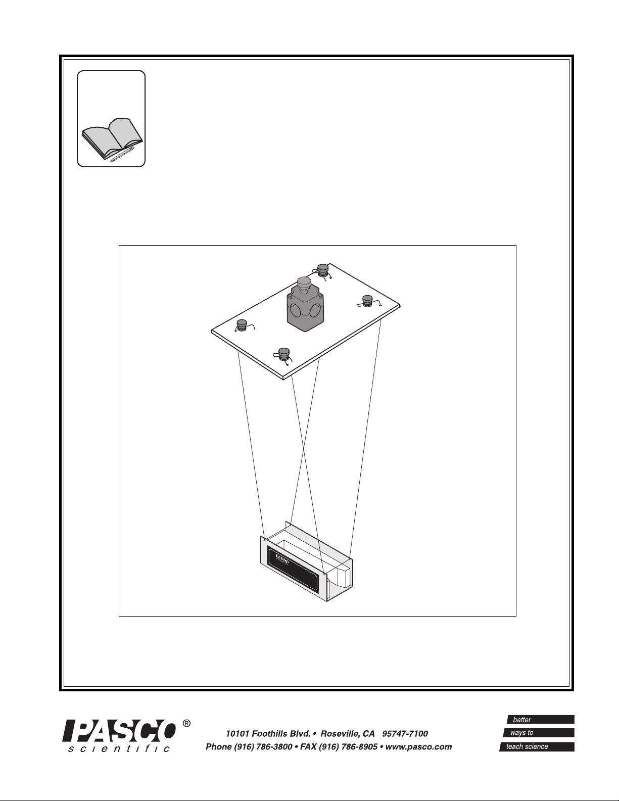
Model ME-6814
MINI CATCHER ACCESSORY
MINI CATCHER
ME-6815
ACCESSORY
© 1996 PASCO scientific $10.00
Page 2

Page 3

012-06293A Mini Catcher Accessory
T able of Contents
Section Page
Copyright, Warranty, and Equipment Return ......................................................i i
Introduction .......................................................................................................1
Equipment.........................................................................................................1
Ball Catcher Setup.............................................................................................2
Velcro Assembly...............................................................................................2
Experiment 1: Ballistic Pendulum......................................................................3
Teacher’s Guide ...........................................................................................9
Technical Support ................................................................................... Back Cover
i
Page 4
Mini Catcher Accessory 012-06293A
Copyright, Warranty and Equipment Return
Please—Feel free to duplicate this manual
subject to the copyright restrictions below.
Copyright Notice
The PASCO scientific 012-06293A manual is copyrighted and all rights reserved. However, permission
is granted to non-profit educational institutions for
reproduction of any part of the Mini Catcher Accessory manual providing the reproductions are used
only for their laboratories and are not sold for profit.
Reproduction under any other circumstances, without
the written consent of PASCO scientific, is prohibited.
Limited Warranty
PASCO scientific warrants the product to be free from
defects in materials and workmanship for a period of one
year from the date of shipment to the customer. PASCO
will repair or replace, at its option, any part of the product
which is deemed to be defective in material or workmanship. The warranty does not cover damage to the
product caused by abuse or improper use. Determination of whether a product failure is the result of a
manufacturing defect or improper use by the customer
shall be made solely by PASCO scientific. Responsibility for the return of equipment for warranty repair
belongs to the customer. Equipment must be properly
packed to prevent damage and shipped postage or
freight prepaid. (Damage caused by improper packing
of the equipment for return shipment will not be
covered by the warranty.) Shipping costs for returning
the equipment, after repair, will be paid by PASCO
scientific.
Equipment Return
Should the product have to be returned to PASCO
scientific for any reason, notify PASCO scientific by
letter, phone, or fax BEFORE returning the product.
Upon notification, the return authorization and
shipping instructions will be promptly issued.
ä
NOTE: NO EQUIPMENT WILL BE
ACCEPTED FOR RETURN WITHOUT AN
AUTHORIZATION FROM PASCO.
When returning equipment for repair, the units
must be packed properly. Carriers will not accept
responsibility for damage caused by improper
packing. To be certain the unit will not be
damaged in shipment, observe the following rules:
➀ The packing carton must be strong enough for the
item shipped.
➁ Make certain there are at least two inches of
packing material between any point on the
apparatus and the inside walls of the carton.
➂ Make certain that the packing material cannot shift
in the box or become compressed, allowing the
instrument come in contact with the packing
carton.
Address: PASCO scientific
10101 Foothills Blvd.
Roseville, CA 95747-7100
Phone: (916) 786-3800
FAX: (916) 786-3292
email: techsupp@pasco.com
web: www.pasco.com
ii
Page 5
012-06293A Mini Catcher Accessory
Introduction
The PASCO ME-6814 Mini Catcher Accessory is used
with the PASCO ME-6825 Mini Launcher to perform
ballistic pendulum experiments. The Mini Catcher
functions as a ball catcher-pendulum. Students can
determine the initial velocity of the projectile, the height
Equipment
The Mini Catcher Accessory includes the following:
• a ball catcher
• support plate from which to hang the catcher
• spool of thread
• Velcro
• (2) chromed steel balls
®
assembly
achieved by the pendulum after ballistic collision with
the steel ball fired from the Mini Launcher, and the
percent loss of kinetic energy as a result of the elastic
collision.
The Mini Catcher Accessory is intended for use in a
supervised classroom setting.
support plate
rod clamp
ball catcher
MINI CATCHER
ME-6815
ACCESSORY
thread
1
Page 6

Mini Catcher Accessory 012-06293A
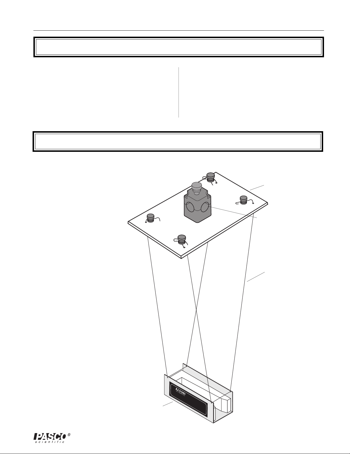
Ball Catcher Setup
Suspending the Mini Catcher as a
Pendulum
Secure the rod clamp on top of the support plate to a
support rod that is clamped to the table. Cut two pieces
of string, each about one and a half meters long. Thread
one string through the front two holes in the ball catcher.
Thread the other through the back two holes in the ball
catcher. Thread the ends of the strings through the holes
in the support plate and secure them, making sure the
catcher hangs level. (See Figure 2.)
rod clamp
support rod
support plate
thread
Velcro Assembly
To enable the user to measure the height to which the
pendulum swings, a thread must be connected between
the ball catcher and the launcher. The amount of extension of the string shows how far the pendulum swung.
One end of the string slips through a Velcro assembly on
the Mini Launcher base, and the other end threads
through a hole in the ball catcher. (See Figure 3.)
➀ Separate the Velcro hook and loop strips.
➁ Cut two square pieces of Velcro hook and one square
piece of Velcro loop.
➂ Determine the approximate height at which the Velcro
assembly will be applied. This is determined by the
approximate height of which the ball catcher hangs.
➃ Remove the protective covering from the back of each
Velcro square.
➄ Arrange the two square pieces of Velcro hook and one
square piece of Velcro loop onto the vertical plate of
the Mini Launcher base as shown (Figure 3).
➅ Cut one piece of Velcro loop 5 – 6 cm long. Do not
remove the protective backing.
support plate
string
MINI CATCHER
ACCESSORY
ME-6815
thumbscrew
ball catcher
➆ Tie a thread to one of the front holes in the ball
catcher as shown (Figure 3).
➇ The other end of this thread will pass between the
square piece of Velcro loop (attached to the Mini
Launcher base) and the long piece of Velcro loop
which should be applied to the three Velcro squares
attached to the Mini Launcher base.
Mini Launcher Base
Mini Launcher
Velcro
thread
Velcro loop
hook
Mini
Catcher
Figure 2. Suspending the Ball Catcher
Figure 3. Velcro Assembly
2
Page 7

012-06293A Mini Catcher Accessory
Experiment 1: Ballistic Pendulum
EQUIPMENT NEEDED
– Mini Launcher and steel balls (ME-6825) – table clamp
– Mini Catcher Accessory (ME-6814) – meter stick
– Universal Table Clamp (ME-9376B) – white paper, carbon paper
– Support Rod (90 cm) (ME-8738) – plumb bob
– Right Angle Clamp (SE-9444) – mass balance
optional: Photogates and Photogate Bracket
Purpose
Students will determine the percent loss of kinetic energy as a result of an elastic collision by
determining the initial and final velocities of the projectile from the Mini Launcher and by using
the laws of Conservation of Energy and Conservation of Momentum.
Theory
A ball is launched horizontally and embeds in
the bob of a pendulum. The pendulum then
swings up to a particular height, h. (See Figure
1.1.)
Momentum is conserved during the collision, but
MINI CATCHER
ACCESSORY
ME-6814
kinetic energy is not. The momentum after the
collision is equal to the momentum before the
collision:
(1)
mbvo= mb+ mcv
Figure 1.1. Conservation of Energy
where mb is the mass of the ball, vo is the muzzle velocity of the ball, mc is the mass of the
catcher, and v is the velocity of the catcher (and ball) after the collision. (See Figure 1.2.)
Before Collision
Launcher
9
8
7
6
5
WEAR
SAFETY
GLASSES
WHEN IN USE.
DON’T PUSH
PISTON
WITH
FINGER!
CAUTION
4
4
3
3
2
2
1
1
0
ME-6825
MINI LAUNCHER
v
o
m
B
MINI CATCHER
ACCESSORY
ME-6814
m
C
Launcher
9
8
7
6
5
4
3
WEAR
2
SAFETY
GLASSES
WHEN IN USE.
DON’T PUSH
2
1
1
0
v
After Collision
PISTON
WITH
FINGER!
CAUTION
4
3
ME-6825
MINI LAUNCHER
MINI CATCHER
ACCESSORY
ME-6814
ME-6814
MINI CATCHER
ACCESSORY
mB + m
v = 0
h
v
C
Figure 1.2. Conservation of Momentum
3
Page 8

Mini Catcher Accessory 012-06293A
y
x
t
x
t
The kinetic energy of the catcher (and ball) after the collision is converted completely to potential
energy at the top of the swing:
1
(2)
mb+ mcv2= mb+ mcgh
2
So to find the muzzle velocity of the ball, we begin with the potential energy of the pendulum at the
top of its swing and work backwards from there. From our equation for energy conservation (2):
v =2gh
(3)
Substitute (3) into the equation for momentum conservation (1):
mbv0= mb+ mc2gh
m
+ m
b
v0=
c
m
2gh
b
For comparison, the initial speed (muzzle velocity) of the ball is determined by shooting the ball
horizontally off the table onto the floor and measuring the vertical and horizontal distances through
which the ball travels.
Setup
➀
For a ball shot horizontally off a table with an initial speed, v
the ball is given by , where t is the time the ball is in the air. Air friction is assumed to be
= v
0
the horizontal distance (x) travelled by
0,
negligible.
2
1
The vertical distance (y) the ball drops in time t is given by .
y=
gt
2
The initial velocity of the ball can be determined by measuring x and y. The time of flight of the ball
can be found using
2
t =
and then the muzzle velocity can be found using .
g
vo=
Part I: Determining the Initial Velocity of the Ball
Clamp the Mini Launcher to a sturdy table near one end of the table. ( See Figure 1.3).
Mini Launcher
steel ball in flight
table
9
DON’T
8
PUSH
PISTON
7
WITH
6
5
CAUTION
4
4
3
WEAR
3
2
2
SAFETY
1
1
0
GLASSES
WHEN IN
ME-6825
MINI LAUNCHER
y
x
Figure 1.3. Setup for Part I: Determining V0, method 1
4
Page 9

012-06293A Mini Catcher Accessory
➁ Adjust the angle of the Mini Launcher to zero degrees so the ball will be shot off horizon-
tally, away from the table onto the floor.
Procedure
➀ Using the pushrod that came with the Mini Launcher, put the steel ball into the Mini Launcher
and cock it in the long range position (three clicks).
➤ Important! Never look down the barrel of the Mini Launcher. You can tell whether the
Mini Launcher is loaded by looking at the viewing window located on the top front of the
barrel. If the window is clear, the Mini Launcher is loaded. If in doubt, place your hand
over the muzzle and pull the trigger.
➁ Fire one shot to locate where the ball hits the floor. At this position, tape a piece of white paper
to the floor. Place a piece of carbon paper (carbon-side down) on top of this paper and tape it
down. When the ball hits the floor, it will leave a mark on the white paper.
➂ Fire about ten more shots.
➃ Using a plumb bob as an aid, measure the vertical distance from the bottom of the ball as it
leaves the barrel (this position is marked on the side of the barrel) to the floor. Record this
distance in Table 1.1.
Find the point on the floor that is directly beneath the release point on the barrel. Measure the
horizontal distance along the floor from the release point to the leading edge of the paper.
Record in Table 1.1.
Measure from the leading edge of the paper to each of the ten dots and record these distances in
Table 1.1.
➄ Find the average of the ten distances and record in Table 1.1.
➅ Using the vertical distance and the average horizontal distance, calculate the time of flight and
the initial velocity of the ball.
➆ Record your data in Table 1.1 and Table
1.4.
Table 1.1 Determining the Initial Velocity
Vertical distance (y) = ______________.
Horizontal distance to paper edge = ____________.
Initial velocity (v
)= _______________.
0
5
Page 10

Mini Catcher Accessory 012-06293A
Alternate Method: Determining the Muzzle Velocity with Photogates
➀ Attach the Photogate Bracket to the launcher and attach two Photogates to the bracket. Plug the
Photogates into a computer or other timer.
➁ Put the ball into the Mini Launcher and cock it to the long range position.
➂ Run the timing program and set it to measure the time between the ball blocking the two
Photogates.
Shoot the ball three times and take the average of these times.
Record in Table 1.2.
Use a distance between the Photogates of 10 cm, to calculate the initial speed and record it in
Table 1.2 and Table 1.4.
Table 1.2 Initial Speed Using Photogates
Trial Number
Average Time
Initial Speed
Part II: Ballistic Pendulum
Setup
➀ Find the masses of the ball and the catcher and
record in Table 1.3.
➁ Suspend the ball catcher as a pendulum as
explained in the general instructions.
➂ With the Mini Launcher mounted as in Figure
1.4, clamp the suspended ball catcher directly in
front of the muzzle.
Time
1
2
3
rod clamp
horizontal rod
90 cm steel rod
➃ Attach a thread to the ball catcher and string it
through the Velcro assembly (see the general
instructions) on the base of the Mini Launcher.
Procedure
➀ Load the Mini Launcher with the steel ball on
the long range setting. Fire a test shot to see how
far out the thread is pulled. Pull a few centimeters of the thread back through the Velcro,
leaving the rest of the thread slack between the
Mini Launcher and the catcher. When the ball is
shot into the pendulum again the thread will
Mini Launcher
9
DON’T PUSH
8
PISTON
WITH
7
FINGER!
6
5
CAUTION
4
4
3
WEAR
3
2
2
SAFETY
1
1
0
GLASSES
WHEN IN USE.
ME-6825
Mini Launcher
base
clamp
Figure 1.4. Setup for Part II
6
MINI LAUNCHER
MINI CATCHER
ACCESSORY
ME-6814
Mini Catcher
table clamp
Page 11

012-06293A Mini Catcher Accessory
E
E
become taut just before the catcher reaches its maximum height. This reduces the effect of
friction on the thread.
➁ Anchor the string on the Mini Catcher base with a piece of tape and measure the perpendicular
distance from the bottom of the Mini Catcher to the table.
➂ Fire the ball into the pendulum five times. After each trial, pull the pendulum back until the
thread is taut and measure the height above the level of the muzzle to which the pendulum
swung. Record in Table 1.3.
Analysis
➀ Calculate the average of the heights in Table 1.3 and record the result in Table 1.4. Using the
average height, calculate the velocity immediately after the collision and record it in Table 1.4.
➁ Using the velocity calculated in the previous step and the masses, calculate the muzzle velocity
of the ball and record in Table 1.4.
➂ Calculate the percent difference between the muzzle velocities found in Parts I and II. Record in
Table 1.4.
Table 1.3 Ballistic
Pendulum Data
Table 1.4 Results
Mass of Ball = _____________.
Mass of Catcher = __________.
Average Height
Height
v0, Method 1 (Part I)
v0, Method 2 (Part II)
v (ball + catcher)
KE before collision
KE after collision
% difference in KE
Questions:
➀ What percentage of the kinetic energy is lost in the collision? Use the masses and velocities to
calculate this percentage:
% Lost =
K
before
KE
- K
before
after
x 100%
➁ Where did the kinetic energy go?
7
Page 12

Mini Catcher Accessory 012-06293A
Notes
8
Page 13

012-06293A Mini Catcher Accessory
Teacher’s Guide
Experiment 1
Hints for successful data collection (Part II):
• Be sure that the Mini Catcher is level and hanging close to, but not touching, the
Mini Launcher.
• Check to be sure the muzzle is aligned with the foam pad.
• Be sure the string moves freely in the Velcro assembly.
• Check to be sure the support plate is perpendicular to the table.
• To be sure any force exerted by the string attached to the Mini Catcher is minimized, leave enough slack in the string to necessitate its being pulled only a few
centimeters at the top of the swing of the Mini Catcher.
• Be sure to tape the string to the Mini Launcher base after firing the Mini Launcher
and before measuring h.
• Be sure students are using for their velocity calculations in Part II the ∆h of the
bottom of the Mini Catcher, not the absolute height above the table top of the
bottom of the Mini Catcher.
A Sample Data Set:
mass of steel ball = .016 kg
mass of Mini Catcher = .024 kg
ave. ∆h = 0.16 m
y = 0.77 m
x = 1.8 m
v
(Part I) = 4.5 m/s
0
v
(Part II) = 4.4 m/s
0
K.E. before collision = 0.15 Joule
K.E. after collision = 0.063 Joule
Loss of K.E. = 58 %
Question 2:
The remainder of the K.E. was converted primarily to heat energy that was dissipated in
the foam pad. Other potential contributors to kinetic energy loss include torque in the
swing path of the Mini Catcher and potential energy in the elastic deformation of the
foam pad by the steel ball.
9
Page 14

Mini Catcher Accessory 012-06293A
Notes
10
Page 15

T echnical Support
Feedback
If you have any comments about the product or
manual, please let us know. If you have any suggestions on alternate experiments or find a problem in the
manual, please tell us. PASCO appreciates any
customer feedback. Your input helps us evaluate and
improve our product.
To Reach PASCO
For technical support, call us at 1-800-772-8700 (tollfree within the U.S.) or (916) 786-3800.
fax: (916) 786-3292
e-mail: techsupp@PASCO.com
web: www.pasco.com
Contacting Technical Support
Before you call the PASCO Technical Support staff, it
would be helpful to prepare the following information:
➤ If your problem is computer/software related, note:
Title and revision date of software;
Type of computer (make, model, speed);
Type of external cables/peripherals.
➤ If your problem is with the PASCO apparatus, note:
Title and model number (usually listed on the
label);
Approximate age of apparatus;
A detailed description of the problem/sequence
of events. (In case you can’t call PASCO right
away, you won’t lose valuable data.);
If possible, have the apparatus within reach when
calling to facilitate description of individual parts.
➤ If your problem relates to the instruction manual,
note:
Part number and revision (listed by month and
year on the front cover);
Have the manual at hand to discuss your ques-
tions.
Page 16

 Loading...