

Page 1

®
Instruction Manu al with
Experimen t Guide and
Human Arm Model
ME-6807A
Teacher’s Notes
012-10359A
Page 2

Human Arm Model Table of Contents
Introduction . . . . . . . . . . . . . . . . . . . . . . . . . . . . . . . . . . . . . . . . . . . . . . . . . . . . . . . . . . .4
Parts of the Arm Model . . . . . . . . . . . . . . . . . . . . . . . . . . . . . . . . . . . . . . . . . . . . . . . . . .4
Clamping the Arm Model to a Lab Bench . . . . . . . . . . . . . . . . . . . . . . . . . . . . . . . . . . . .5
Locking or Limiting Shoulder Movement . . . . . . . . . . . . . . . . . . . . . . . . . . . . . . . . . . . . . 5
Adjusting the Wrist Angle. . . . . . . . . . . . . . . . . . . . . . . . . . . . . . . . . . . . . . . . . . . . . . . . . 5
Attaching the Mass . . . . . . . . . . . . . . . . . . . . . . . . . . . . . . . . . . . . . . . . . . . . . . . . . . . . . 5
Holding a Ball. . . . . . . . . . . . . . . . . . . . . . . . . . . . . . . . . . . . . . . . . . . . . . . . . . . . . . . . . .5
Attaching Cords to the Arm Model . . . . . . . . . . . . . . . . . . . . . . . . . . . . . . . . . . . . . . . . . 6
How Angles are Measured. . . . . . . . . . . . . . . . . . . . . . . . . . . . . . . . . . . . . . . . . . . . . . . . 6
Using Sensors with the Arm Model . . . . . . . . . . . . . . . . . . . . . . . . . . . . . . . . . . . . . . . . .7
Replacing the Elbow-stop Pad. . . . . . . . . . . . . . . . . . . . . . . . . . . . . . . . . . . . . . . . . . . . . 8
Replacement Parts . . . . . . . . . . . . . . . . . . . . . . . . . . . . . . . . . . . . . . . . . . . . . . . . . . . . . 8
About the Experiments. . . . . . . . . . . . . . . . . . . . . . . . . . . . . . . . . . . . . . . . . . . . . . . . . . . 8
Experiment 1: Biceps Force versus Perpendicular Load. . . . . . . . . . . . . . . . . . . . . . . . . 9
Experiment 2: Biceps Force versus Weight. . . . . . . . . . . . . . . . . . . . . . . . . . . . . . . . . . 11
Experiment 3: Triceps Force versus Perpendicular Load . . . . . . . . . . . . . . . . . . . . . . . 13
Experiment 4: Biceps Curl . . . . . . . . . . . . . . . . . . . . . . . . . . . . . . . . . . . . . . . . . . . . . . . 15
Experiment 5: Biceps Force versus Shoulder Angle, Constant Elbow Angle . . . . . . . . 17
Experiment 6: Biceps Force versus Elbow Angle, Constant Forearm Orientation. . . . .19
Experiment 7: Triceps Extension. . . . . . . . . . . . . . . . . . . . . . . . . . . . . . . . . . . . . . . . . . 21
Experiment 8: Rotational Inertia of the Forearm . . . . . . . . . . . . . . . . . . . . . . . . . . . . . . 23
Demonstrations: Complex Movements . . . . . . . . . . . . . . . . . . . . . . . . . . . . . . . . . . . . . 25
Teacher’s Notes. . . . . . . . . . . . . . . . . . . . . . . . . . . . . . . . . . . . . . . . . . . . . . . . . . . . . . . 28
Technical Support . . . . . . . . . . . . . . . . . . . . . . . . . . . . . . . . . . . . . . . . . . . . . . . . . . . . . 34
Page 3
Human Arm Model
ME-6807A
1
11
3
2
4
5
6
7
8
9
10
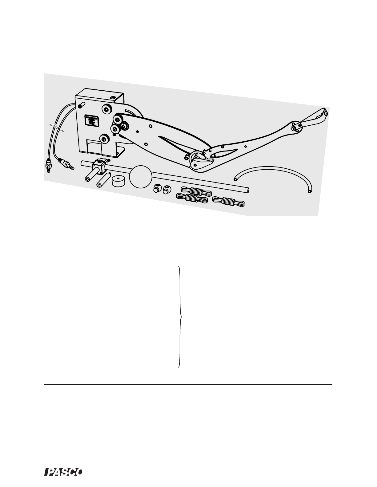
Included with ME-6807A Replacement Part Number
1. Human Arm Model ME-6807A
2. 45 cm Rod ME-8736
3. Sensor-mounting Clamp
4. Sensor-mounting Studs, 2 pieces
5. 100 g Mass
6. Hollow Rubber Ball, 57 mm diameter
7. Cord Locks, 2 pieces
ME-6808 (Human Arm Model Spares Kit)
8. Cord, 2 90 cm pieces
9. Elastic Cord, 60 cm
10. Tubing for replacing elbow stop pad, 29 cm
11. Thumbscrew and nut for attaching mass
Also included with PS-2611 Part Number
Angle Sensor PS-2139
Other recommended equipment
Angle Sensor PS-2139
Force Sensors (2 recommended) PS-2104
C-clamp
SE-7286 (6-pack)
or
Large Table Clamp
®
ME-9472
or
PS-2189
3
Page 4
Human Arm Model Introduction
Introduction
The Human Arm Model simulates the muscles and motion of an actual hum an a r m.
Changes in position are measured at the shoulder and elbow using the two built-in
potenti o me ters. Cords representi ng the biceps and tr iceps muscles attach to the arm.
Students can pull the cords to make the arm move and use f orce sensors to measure
the forces exerted by the muscles.
This manual includes:
• instructi ons for setting up the arm model (s tarting on page 5),
• various experiments (page 9),
• demonstrations of complex movements (page 25), and
• teacher’s notes and sample data for the experiments (page 28).
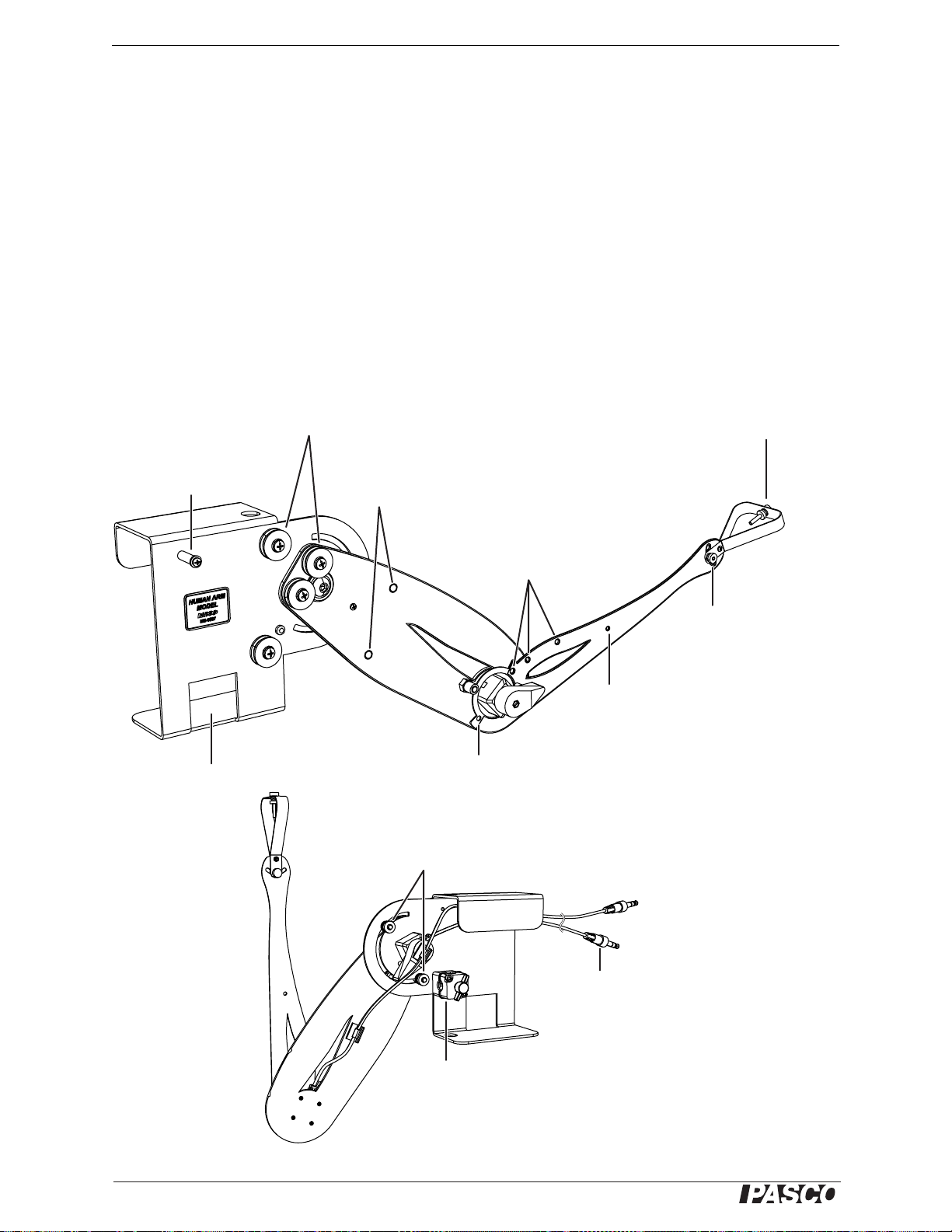
Parts of th e Arm Mo del
pulleys
screw for
attaching mass
attaching co rd
base
post for
cutout for
C-clamp
holes for
sensor-mounting
studs
biceps insertion
points
screw for
locking wrist
forearm
center of
mass
triceps insertion point
shoulder
stops
angle
sensor
plugs
rod clamp
Figur e 1: Parts of the arm mo de l
4
®
Page 5
ME-6807A Clamping the Arm Mo del to a Lab Bench
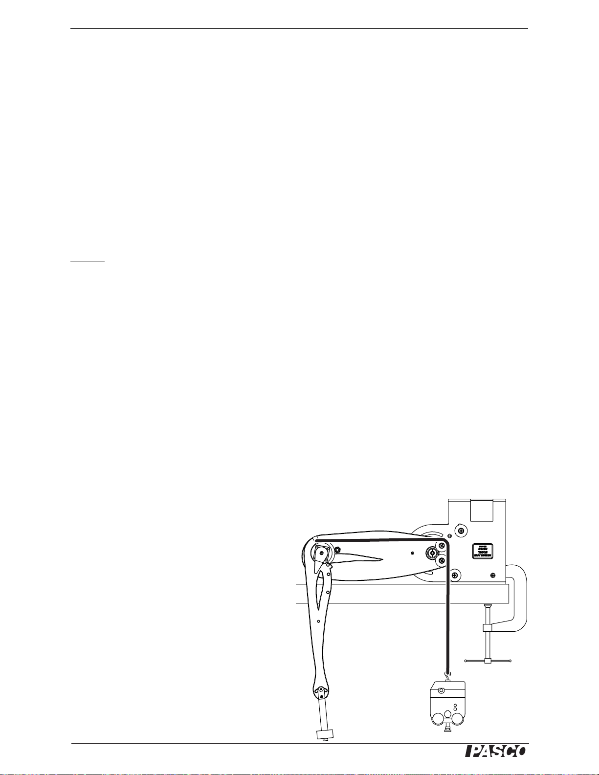
Clamping the Arm Model to a Lab Bench
The base of the arm model must be clamped to a stable obje ct such as a lab bench.
This can be done with a C-clamp or with a model ME-9472 Large Table Clamp.
Depending on how you will use the mode l, you can clamp the base horizontally, vertically, or upside down.
Figure 2: Various ways
to orient and secur e
the arm model
Locking or Limiting Shoulder Movement
The shoulder can be locked at an angle, or its movement can be limited, using the
adjustable s houlder stops (see Figure 3). L oosen one of the shoulder sto p nuts , s lide
the stop to the desi red positio n, an d tighten the nut. Repeat for the ot her shoulder s top.
Adjusting the Wrist Angle
Loosen the wrist nut, change the position of the hand, and tighten the nut (Figure 4a).
Attaching the Mass
Use the included scre w and nut to attach the 100 g mass to the hand (Figure 4b).
Holding a Ball
Adjust the angles of the shoulder, elbow, and wrist to make the hand horizontal. Place
the ball on the hand (Fi gure 4c).
100 g
loosen nut to
adjust wrist
mass
loosen nut
and slid e
into positio n
Figure 3: Adjustable
shoulder stops
ball
abc
Figure 4: The hand
®
5
Page 6
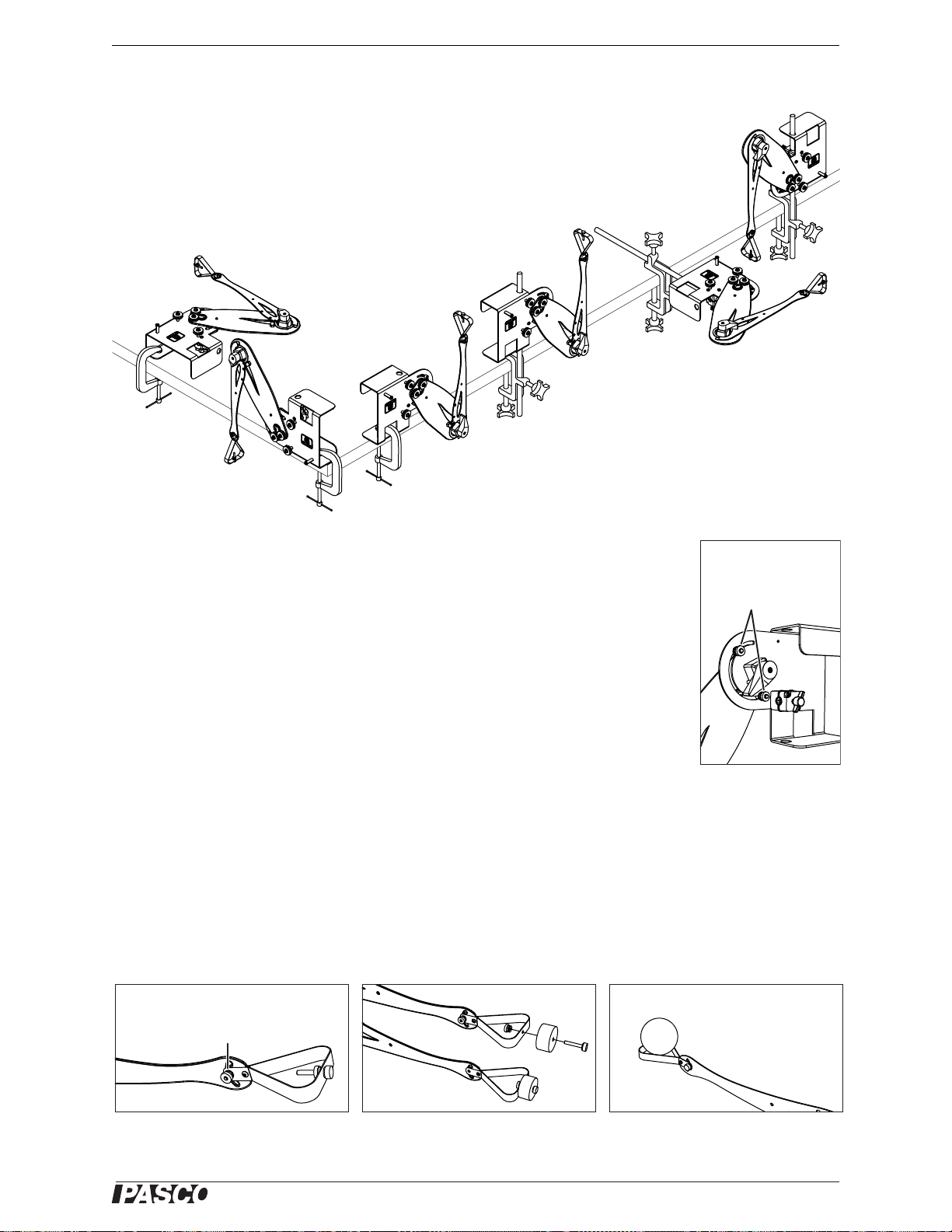
Human Arm Model Attaching Cords to the Arm Model
Attaching Cords to the Arm Model
Cords ar e us ed to re p r esent the mu s c le s of
inner biceps insertion po int
standard biceps insertion point
the upper arm. Depending on how you will
use the model, you can attach one or two
cords, u se s ta n d ar d co rds o r elastic cord s ,
and run the cords over and under the pulleys
in various ways.
The biceps cord can be atta ch ed at the stan-
triceps
insertion
point
Figure 5: Muscle insertion points
dard muscle in sertion point, represen ting a
human arm, or at one of the other two insertion points, for more or less leverage (Figure 5).
1. Tie a knot near the end of a cord and thread the other end through one of the
insertion poi nt holes. Pull the cord th rough until the knot stops aga inst the hole
(Figure 6).
2. Run the cord over and under the pulleys in the desired configuration. (For exam-
ples, see the expe riments and demonstrations starting on page9.)
3. Use one of th e in clu d e cor d lo cks to make a loo p in t he f r ee end of the co rd . Pl ac e
the loop over a post or a force sensor hook. Adjust the length of the cord. Push
the cord lock against the post or hook and tie a knot against the cord lock to prevent it from slipping (F igure 7).
outer biceps insertion point
Figure 6: Cord attached
to insertio n poin t
How Angles are Measured
The angle sensor determines the shoulder and elbow angles from the resistance of the
potentiometers built into the joints. Figure 8 shows how the angles are measured.
shoulder
angle
elbow
angle
Figure 7: Cord attached
to force sensor with
cord lock
Figure 8: H ow ang les are meas ur e d
6
®
Page 7
ME-6807A Using Sensors wi th the Ar m Model
Using Sensors with the Arm Model
Note: For more information about angle sensors, force sensors, and interfaces, see the instructions supplied with those devices.
Angle Sensor
1. Connect the cable from the elbow to Channel 1 of the angle sensor.
2. Connect the cable from the shoulder to Channel 2 of the angle sensor.
3. Connect the angle sensor to y o u r PASPORT interface.
4. If you are using a compute r, connect the PASPORT interface to it and start
DataStudio.
Force Sens or
1. Conne ct a fo rc e sensor to th e s ame PASPO RT inter f ac e as th e ang l e s en so r (i f it
is a multi-port interface) or to a separate inte r f ace.
2. Use one of the included cord locks to make a loop in the biceps or triceps cord
and attach it to force sensor’s hook (see “Attaching Cords to the Arm Model” on
page 6).
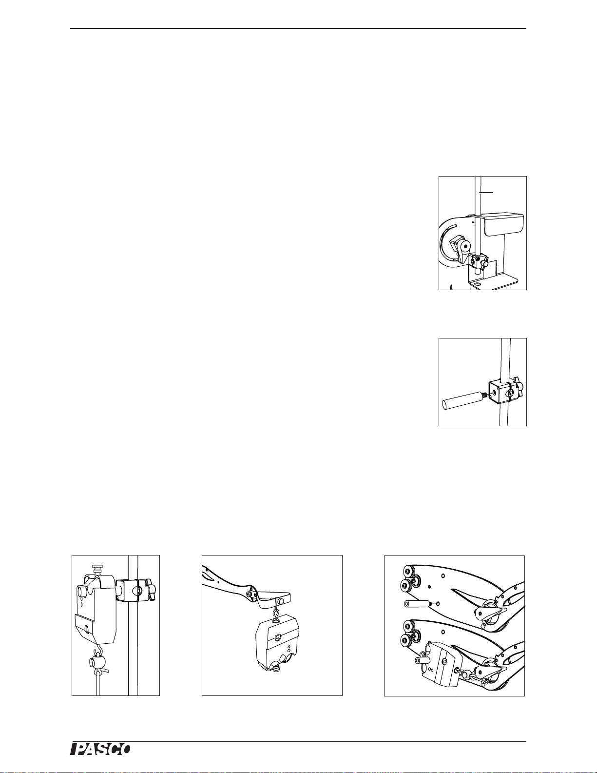
3. Clamp the include d 45 cm rod to the base of the arm model (Figure 9).
4. Secure the inc luded se nsor cl amp to t he rod. Sc rew the sen sor st ud into t he cla mp
(Figure 10).
5. Mount the force sensor on the stud (Figure 11).
Repeat steps 1 and 2 to add a second force sensor.
For some experiments, the second force sensor is used to apply a load to the model’s
hand. You can hook the force sensor dir ectly onto t he hand, or , for more fl exibi lit y, tie
a loop of string to the hand (Figure 12).
rod
Figure 9: Rod clamped
in base
Figure 10: Sensor stud
and clamp
To mount a force sensor on the upper arm , screw a sensor stud into one of the
threaded holes. (See Figure 13, and Experiment 5 on page 17.) Use the upper hole to
place the sensor in the biceps position or the lower hole for the triceps position. This
allows the elb o w an g le to stay consta n t w hi l e the shoul d er is r o ta ted.
Figure 11: Force sensor
on rod
®
Figure 12: Force sensor attached to
hand with string
Figure 13: Force sensor attached to
upper arm and triceps cord
7
Page 8

Human Arm Mod el Replacing the Elbow-stop Pa d
Replacing the Elbow-stop Pad
The post that limits the trave l of the elbow is padded with pla sti c tubing. If the plas tic
become s worn, complete these steps to replace i t.
1. Use a sharp knife to remove the old pad.
2. Cut a 10 mm piece from tubing inclu d ed with the arm model.
3. Press the piece of tubing onto the post (F igure 14).
Figure 14: Elbow-stop
pad replacement
Replacement Parts
The Human Arm Mode l Spares Kit (PASCO part ME-6808) is available to replace
lost or worn parts. It contains:
• Cord, inelastic (120 cm)
• Elastic cord (60cm)
• Cord locks (10)
•Balls (3)
• 100 g masses (2)
• Screws and nuts for attaching mass to hand (2 of each)
• Sensor-mounting clamps (2)
• Sensor-mounting studs (2)
• T-screws for rod clamp (4)
• Shoulder stops (2)
• Bumper that contacts s houlder stops (1)
• Screws and nuts for locking wrist (2 of each)
• Tubing for replacing elbow stop pad (30 cm)
About the Experiments
Experiments are presented on the following pages as examples of ways to set up and
use the arm model. In many of these exp eriments, students are asked to perform an
action with the ir own arms and make predic tions before rep roducing the acti on on the
arm model. Teacher's notes and sample data can be found on page 28.
8
®
Page 9
Experiment 1: Biceps Force versu s Perpendicular Load
Required Parts of Human Arm Model
Arm
Cord ( 1 piece)
45 cm rod
Sensor- m o un t in g cl am p and stud
Other Required Equipment
or
2 Force Sensors PS-210 4
C-clamp SE-7286 (6-pack)
Introduction
Hold your arm in front of you with you r elbow bent at 90°. Now have your partner
pull your hand to try t o strai ghten yo ur elbow. Resist the load forc e so th at your e lbow
remains at 90°.
Predictions
1. Which muscle (the biceps or triceps) did you use to resist this load? How do you
know?
PS-2189
2. Was the muscle force greater than, less than, or equal to the load force applied to
your hand?
3. If you partner pulls your hand with a force of 1 N,
guess how much muscle f orce is needed to keep your
elbow at 90°.
Force Sensor 1
(Biceps Force)
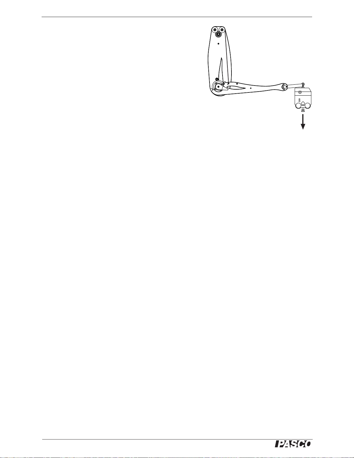
Set-up
1. Clamp the arm model horizontally as illustrated.
2. Clamp the rod to t he bas e of the m odel a s ill ustra ted. Use
the sens o r clamp and stud to at tach a force sensor t o th e
rod.
3. Lock the shoulder at 0°.
4. Attach a cord as illustrated. Adjust the length
of the cord so that the elbow is held at about
90°.
5. Conn ect tw o f o rce sensors to your interf a c e .
The second force sensor will be held in your hand and
apply the load force to the model’ s hand.
6. Set the sampling rate of both force sensors to 20 Hz.
7. Prepare a graph to plot bic eps force versus load force.
®
9
Page 10
Human A rm Model Experiment 1: B iceps Force vers us Perpendicular L oad
Procedure
1. Start data collection.
2. Hook the second force sensor onto to the model’s hand and
pull in the direction indicated in the illustration. Slowly
increase the force while watching the graph.
3. When the load force reaches about 2 N, stop data collection.
Force Sensor 2
(Load Force)
Analysis
1. Using words and numbers, explain the relationship between load forc e and
biceps force.
2. Were your predictions accurate? Explain.
Further Analysis
1. Draw a free-body diagr am showi ng all forces (in the plane of rot ation) acting on
the forearm.
2. What is the net force on the forearm?
3. What is the net torque?
Furt her Study
1. Repeat the experiment with the elbow at a different angles, but keep the load
force perpendicular to the forearm. How does the ratio of biceps force to load
force change for elbow angles greater an d less than 90°?
2. Repeat the experiment wit h th e cord attached at t h e o ther two biceps ins er tion
points.
10
®
Page 11
Experiment 2: Biceps Force versu s Weight
Required Parts of Human Arm Model
Arm
Cord ( 1 piece)
45 cm rod
Sensor- m o un t in g cl am p and stud
Other Required Equipment
or
2 Force Sensors PS-210 4
C-clamp SE-7286 (6-pack)
Introduction
Let your arm hang vertically at your side. While keeping your upper arm vertical ,
bend your elbow at 90° so that your forearm is horizontal. Hold your palm up. Have
your partner place a mass in your hand, but don't let your arm move.
Predictions
1. If the mass in your ha nd is 10 0 g (so it s weigh t is 0. 98 N), how much bi ceps forc e
is needed to keep your elbow at 90°? (Assume that your triceps is relaxed.)
PS-2189
2. If you double the mass in your ha nd (so the load force doubles), does the biceps
force double?
3. If you remove the mass from your hand, does the
biceps force go to zero? Explain your answer.
Force Sensor 1
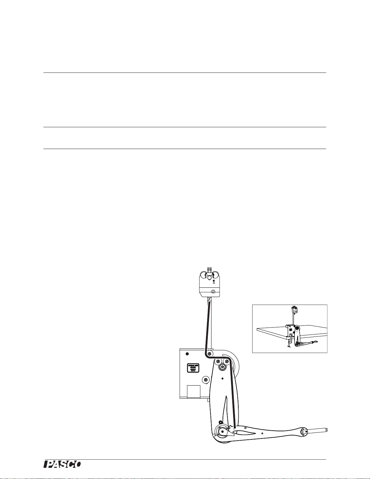
Set-up
(Biceps Force)
1. Clamp the arm mode l vertically as illustrated.
2. Clamp the rod to t he bas e of the m odel a s ill ustra ted. Use
the sens o r clamp and stud to at tach a force sensor t o th e
rod.
3. Lock the shoulder at 0°.
4. Attach a cord as illustrated. Adjust the length
of the cord so that the elbow is held at about
90°.
5. Conn ect tw o f o rce sensors to your interf a c e .
The second force sensor will be held in your
hand and apply the load force to the model’s hand.
6. Set the sampling rate of both force sensors to 20 Hz.
7. Prepare a graph to plot bic eps force versus load force.
®
11
Page 12

Human A rm Model Experiment 2: Biceps Force versus Weight
Procedure
1. Start data collection.
2. Hook the second force sensor onto to the model’s hand and
pull down to simul ate a weight held in the hand. Slowly
increase the force while watching the graph.
3. When the load force reaches about 2 N, stop data collection.
Force Sensor 2
(Load Force)
Analysis
1. Using words and numbers, explain the relationship between load forc e and
biceps force.
2. Were your predictions accurate? Explain.
Further Analysis
1. Draw a free-body diagr am showi ng all forces (in the plane of rot ation) acting on
the forearm.
2. What is the net force on the forearm?
3. What is the net torque?
Furt her Study
Repeat the experiment with the elbow at different angles. The applied force should
always be straight down to simulate the weight of a mass held in the hand. How does
the relatio ns hip between biceps force and load force change for elbow angles greater
and less than 90°?
Variation
Instead of using a force sensor to apply the load force, hang a known mass from the
hand. Add mass incrementally while measuring biceps force.
12
®
Page 13

Experiment 3: Triceps Force versu s Perpendicular Load
Required Parts of Human Arm Model
Arm
Cord ( 1 piece)
45 cm rod
Sensor- m o un t in g cl am p and stud
Other Required Equipment
or
2 Force Sensors PS-210 4
C-clamp SE-7286 (6-pack)
Introduction
Hold your arm in front of you with you r elbow bent at 90°. Now have your partner
push your hand towa rd you to try to bend your elbow further. Resist the load force so
that your elbow remains bent at 90°.
Predictions
1. Which muscle (the biceps or triceps) do you use to resist this load?
How do you know?
PS-2189
2. Is the muscle fo rce gr eate r, less than, or equal to the load force applie d
to your hand?
3. If you p artner pushes y our hand with a force of 1 N, how much muscle
force is needed to keep your elbow at 90°?
Set-up
1. Clamp the arm model horizontally as illustrated.
2. Clamp the rod to the base of the model as il lustrated.
Use the sensor clamp and stu d t o attach a force sensor
to the ro d.
3. Lock the shoulder at 90°.
4. Attach a cord as illustrated. Adjust the length of the
cord so that the elbow will be held at about 90°.
5. Conn ect tw o f o rce sensors to your interf a c e . T h e sec-
ond force sensor will be hel d in your hand
and apply the load force to the model’s hand.
6. Set the sampling rate of both force sensors to
20 Hz.
Force Sens or 1
(Triceps Force)
7. Prepare a graph to plot triceps force versus
load fo rc e.
®
13
Page 14

Human A rm Model Experimen t 3: Triceps Force v ersus Perpendicu lar Load
Procedure
1. Start data collection.
2. Hook the second force sensor onto to the model’s hand and pull in the direction
indicated in the illu s tr a ti on. Slow ly incre ase the force wh il e w at c h i n g th e graph.
3. When the load force reaches about 2 N, stop data collection.
Analysis
1. Using words and numbers, explain the relationship between load forc e and tri-
ceps force.
2. Were your predictions accurate? Explain.
Further Analysis
1. Draw a free-b ody diagram showing all forces (in the plane of rotation) acting
on the forearm.
2. What is the net force on the forearm?
3. What is the net torque?
Force Sensor 2
(Load Force)
14
®
Page 15

Experiment 4: Biceps Curl
Required Parts of Human Arm Model
Arm
Cord ( 1 piece)
100 g mass
Other Required Equipment
Angle Sensor PS-2139
or
Force Sensor PS-2104
C-clamp SE-7286 (6-pack)
Part A
Introduction
Let your arm hang vertically at your side. Hold a mass in your hand. Without moving
your upper arm, flex your el bow to lift the mass.
Predictions
PS-2189
1. As you lift the mass, does your biceps force increase
or decrease?
2. Sketch your prediction of the biceps force versus elbow
angle graph.
Set-up
1. Install the 1 00 g mass on the model’s hand.
2. Clamp the arm mode l vertically as illustrated.
3. Lock the shoulder at 0°.
4. Attach a cord and force sensor as illustrated. You will hold the force s ensor in
your hand and pull to make the model’s elbow flex.
5. Connect the arm model to the angle sensor. Connect the angle sensor and force
sensor to your interface.
6. Set the sampling rate of the force sensor to 20 Hz.
7. Prepare a graph to plot biceps force versus elbow angle.
Procedure
1. Start data collection.
2. Pull with the force sensor to slowly flex the elb ow from about 5° to 130°.
®
15
Page 16

Human Arm Mod el Experiment 4: Biceps Curl
3. Stop data collection.
Analysis
1. Is the gr aph li n ear?
2. As the elb ow flexes d oe s th e b ic ep s f orce incre ase or decre as e ?
Part B
Introduction
The motion s tudied in this part is similar to that of the last part, but the upper arm is
held at an angle rather than vertical.
Hold a mass in your hand. Rest your elbow on the back of a chair so that your upper
arm is at about 45 degrees from vert ical. Starting with your elbow straight, flex your
elbow to li f t th e mass.
Predictions
1. As you lift the mass, does your biceps force increase or decrease?
2. Sketch your prediction of the biceps force versus elbow angle graph.
Set-up
1. Reposition the shoulder and lock it at 45°.
2. Hold force sensor in th e pos i-
tion illustrated.
Procedure
1. Start data collection.
2. Pull with the force sensor to slowly flex the
elbow from about 5° to 130°.
3. Stop data collection.
Analysis
1. Is the gr aph li n ear?
2. As the elb ow flexes d oe s th e b ic ep s for c e in crease or de cr e ase?
Furt her Study
Find a shoulde r angle fo r which the biceps for ce is nearly consta nt as the el bow flexes
from 10° to 130°.
16
®
Page 17

Experiment 5: Biceps Force versus Shoulder Angle, Constant Elbow Angle
Required Parts of Human Arm Model
Arm
Cord ( 1 piece)
100 g mass
Sensor- m o un t in g st ud
Other Required Equipment
Angle Sensor PS-2139
or
Force Sensor PS-2104
C-clamp SE-7286 (6-pack)
Introduction
Hold a mass in your hand with your elbow at 90° so that your upper arm hangs vert ically and your forearm is horizontal. While keeping your elbow bent at 90°, lift the
mass by rotating your entire arm forwa rd about your shoulder.
PS-2189
Predictions
1. As you lift the mass, does your biceps force increase or decrease?
2. Sketch your prediction of the biceps force versus shoulder angle graph.
Set-up
1. Install the 100 g mass on the
model’s hand.
2. Clamp t he arm mode l ver ticall y as
illustrated.
3. Use a sensor stud to attach the
force sensor to the upper arm in
the biceps position as illustrated.
4. Attach a short cord betw ee n the
forearm and the fo rc e sen sor as
illustr ated. Adjust the length of
the cord (or the clamped pos ition
of the force sensor) so that the
elbow is bent at 90°.
1
5. Connect the arm mode l to the
angle sensor. Connect the angle sensor and force se nsor to your interface.
1
Older versions of the Human Arm Model do not include holes for attaching a sensor stud to the upper
arm. If you have an older version, use a C-clamp to attach the force sensor
®
17
Page 18

Human Arm Model Exp eriment 5: Biceps Force versu s Shoulder A ngle, Consta nt Elbow
6. Set the sampling rate of the force sensor to 20 Hz.
7. Prepare a graph to plot biceps force versus shoulder a ngle.
Procedure
1. Start data collection.
2. Push the upper arm to rota te the shoulder from 0 degrees to about 85 degrees.
(Don’t touch the forearm or force sensor as you do this. )
3. Stop data collection.
Analysis
1. Is the gr aph li n ear?
2. As the arm lifts the mass (increasing the shoulder angle) does the biceps force
increase or decreas e?
18
®
Page 19

Experiment 6: Biceps Force versu s Elbow Angle, Constant Forearm Orientation
Required Parts of Human Arm Model
Arm
Cord ( 1 piece)
100 g mass
45 cm rod
Sensor- m o un t in g cl am p and stud
Other Required Equipment
Angle Sensor PS-2139
or
Force Sensor PS-2104
C-clamp SE-7286 (6-pack)
Introduction
Hold a mass in your hand with your elbow at 90° so that your upper arm hangs vert ically and your forearm is horizontal. While keeping your forearm horizontal, extend
your arm forward as if you are handing the mass to someone.
PS-2189
Predictions
1. As you push the mass forward, does your elbow flex or extend?
2. Does your biceps force increase or decrease?
3. Sketch your prediction of the biceps force versus
elbow angle graph.
Set-up
1. Install the 1 00 g mass on the model’s hand.
2. Clamp the arm mode l vertically as illustrated.
3. Use rods and cl amps to atta ch a for c e s en so r
to the base of the model.
4. Attach a cord as illustrated. Adjust the length
of the cord so that the elbow is at 90° when
the shoulder is at 0°. (With this cord arrangement, the forearm will remain approximately
horizontal as the shoulder rotates forward.)
5. Connect the arm mode l to the angle sensor. Connect the
angle sensor and force se nsor to your interface.
6. Set the sampling rate of the force sensor to 20 Hz.
®
19
Page 20

Human Arm Model Experiment 6: B iceps Force ve rsus Elbow A ngle, Const ant Forearm
7. Prepare a graph to plot biceps force versus elbow angle.
Procedure
1. Start data collection.
2. Push the upper arm to rota te the shoulder from 0 degrees to about 85 degrees.
(Don’t t ouch the forearm or force sensor as you do this.) The elbow will automatically ex t en d .
3. Stop data collection.
Analysis
1. As the arm pushes the mass forward, does the elbow angle increas e or de crease?
2. Does the biceps force increase or decrease as the arm pushes the mass forw ard?
(Note that the extending motion of the arm is represented by right-to-left move-
ment on the graph.)
20
®
Page 21

Experiment 7: Triceps Extension
Required Parts of Human Arm Model
Arm
Cord ( 1 piece)
100 g mass
Other Required Equipment
Angle Sensor PS-2139
or
Force Sensor PS-2104
C-clamp SE-7286 (6-pack)
Part A
Introduction
Hold a mass in yo ur ha nd. St re tch your arm s traigh t up. Be nd y our
elbow at 90° so that your fore arm is horizontal and your hand is
close to the back of your head. While keeping your upper arm vertical, li ft the mass by extending your elbow.
PS-2189
Predictions
1. As you lift the mass, does your triceps force increase or
decreas e?
2. Sketch your p redi ction of the t riceps f orce versus elbo w angle
graph.
Set-up
1. Install the 100 g mass on the
model’s hand.
2. Clamp the arm model vertically and upside-down as illustrated.
3. Lock the shoulder at 0° (straight up).
4. Attach a cor d and force sensor as illustrated. You will hold the force sen-
sor in your hand and pull to make the model’s elbow extend.
5. Connect the arm mode l to the angle sensor. Connect the angle sensor
and force sensor to your inte rface.
6. Set the sampling rate of the force sensor to 20 Hz.
7. Prepare a graph to plot triceps force versus elbow
angle.
®
21
Page 22
Human Arm Model Experiment 7: Triceps Extension
Procedure
1. Hold the forearm horizontal by pulling with the f orce se nsor.
2. Start data collection.
3. Pull with the force sensor to slowly extend the elbow from about 90° to 10°.
4. Stop data collection.
Analysis
1. As the arm lifts the mass, does elbow angle increase or decrease?
2. Does the tricep s fo rce incre ase or decrease? (N ot e th a t th e extend i ng m o t io n of
the elbow is represented by right-to-left movement on the graph.)
Part B
Introduction
The motion studi ed in this part is similar to that of Part A, but the upper arm is held
horizontally rather than vertically.
Hold a mass in your hand. Lean forward and rotate your shoulder back so that your
upper arm is horizontal. Bend your elbow at 90 degrees so that your f orea r m hangs
straight down. While keeping your upper arm horizontal, lift the mass by extending
your elbow.
Predictions
1. As you lift the mass, does your triceps force increase or de crease?
2. Sketch your predic tion of the triceps forc e versus elbow angle graph.
Set-up
1. Reposition the model’ s shoulder and lock it at 90°.
2. Hold force sensor in th e pos ition illustrated.
Procedure
1. Start data collection.
2. Pull with the force sensor to slowly extend the
elbow from about 85° to 15°.
3. Stop data collection.
Analysis
Compare this grap h to the graph from Part A.
22
®
Page 23

Experiment 8: Rotational Inertia of the Forearm
Required Parts of Human Arm Model
Arm
Elasti c cord
45 cm rod
Sensor- m o un t in g cl am p and stud
Other Required Equipment
Angle Sensor PS-2139
or
Force Sensor PS-2104
C-clamp SE-7286 (6-pack)
Introduction
In this experiment, you will use two different methods to estimate the rotational inertia of the forearm with the elbow as the axis of rotati on. In part A, you will measure
the period of oscillation. In part B, you will apply a known force and measure the
resulting angular acceleration.
PS-2189
Part A
Set-up
1. Clamp the arm model ups ide down as illustrated.
2. Lock the shoulder in place with the upper arm approximately horizontal.
3. Set the sampling rate of the angle sensor to 200 Hz.
4. Prepare a graph to plot elbow angle versus time.
Procedure
1. Start data collection.
2. Displace the forearm and release it so that it oscillates freely.
3. After the forearm stops moving, stop da ta collection.
Analysis
The rotationa l inertia (about the axis of the elbow) is given by ,
where T is the period of oscillation (at small amplitudes ) , M =0.10kg is the mass of
the forearm and hand, g =9.8m/s
2
, and d = 0.14 m is the distance from the elbow to
the center of mass (the center of mass is marked by a hole).
IT2Mgd 4π2()⁄=
1. Determine T from the graph of elbow angle versus time.
2. Use this value of T to determ i n e th e rotati o n a l ine r ti a.
®
23
Page 24

Human Arm Model Experiment 8: Rotational Inertia of the Forearm
Part B
Set-up
1. Clamp the arm
model horizontally as illustrated.
2. Clamp the rod t o the base of
the model as illustrated. Use the
sensor cla mp and stud to at ta ch th e f orce
sensor to the rod.
3. Attach an elastic cord as illustrated. Adjust the length of
the cord so that the cord is under slight tension when the elbow is fully flexed.
4. Connect the force sens or to your interface.
5. Set the sampling rate of the force sensor to 200 Hz.
6. Prepare graphs to plot elbow angle, angular velocity (in rad/s), and biceps force
versus time.
7. Set up the software so that you can see the angle reading as you take data.
Procedure
1. Start data collection.
2. Pull the forearm and hold it at 79°.
3. Release the forearm and let it move freely as the elastic cord contr acts.
4. Stop data collection.
Analysis
For this analysis we will look at the angular acceleration when the elb ow angle is
about 90°. T he rotational inertia is (approximately) , where r = 0.045 m is
the distance from the elbow to the insertion poi nt, F is the biceps force, and α is the
rotational acceleration.
1. On the graph of angle versus time, ide ntify the time span during which the elbow
rotates from 80° to 100°.
2. Over the same time span, find the average force, F.
IrFα⁄=
3. Over the same time span, fit a line to the angular velocity versus time plot. The
slope of this line is α.
4. Use thes e v alues of F and α to determine the rotational inertia.
24
®
Page 25

Demonstrations: Complex Movements
Required Parts of Human Arm Model
Arm
Cord ( 2 piece)
100 g mass
Ball
45 cm rod
Sensor- m o un t in g cl am p and stud
Other Required Equipment
Angle Sensor PS-2139
or
2 Force Sensors PS-210 4
C-clamp SE-7286 (6-pack)
Introduction
In the following demonstrations, the arm model is set up to perform motions involving simultaneous rotation of the shoulder and elbow. They are shown here with two
force sensors; howev er they can also be done without sens ors . Note that each cord in
these arrangements makes both joints move and, the refore, represents combinations
of muscles (not just the biceps or triceps).
PS-2189
“Curling Lif t”
1. Set up the arm model with two force sensors as illustrated. The
lower force sensor i s attac hed to t he rod cl amped to th e mode l’ s bas e. The
upper force sensor will be held in your hand.
2. Pull the upper force sensor. Both shoulder and elbow rotate in the
same direction to lift the hand.
3. Attach the 10 0g mass to the hand and repeat to see how the additional load
affects the muscle forces.
The graph
shows data for
lifting the
100 g mass.
biceps
triceps
elbow
shoulder
®
25
Page 26

Human Arm Model Demonstrations: Complex Movements
“Passing Lift”
1. Set up the arm model with two force sensors as illustrated.
The upper force sen sor is attached to the rod clamp ed to the
model’s base. The lower force sensor will be held in your
hand.
2. Pull the lower force sensor. The shoulder rotates for-
ward and elbow extends to keep the fore arm approximate ly ho r i zontal.
3. Attach the 100 g mass to the hand and repeat to see
how the additional load aff ects the muscle forces.
The graph shows data for lifting the 100 g mass.
biceps
elbow
shoulder
triceps
26
®
Page 27

ME-6807A Demonstrations: Complex Movements
“Free Throw”
When using the arm model to th row a bal l (or make an y other
sudden movement), do not let the parts of the arm cras h into
the end stops. P ASCO recomm en ds the “free throw” as a demonstration performed by an instructor, rather than a student
activity.
1. Set up the arm
model as ill ustrated.
The force sensor will
be held in your hand
and is connected to
the triceps insertion
point using standard
cord. El ast ic co r d is
connected between
the biceps insertion
point and the upper
shoulder pulley.
2. Set the lowe r shoulder stop to
hold the shoulder at about 130°.
Move the upper shoulder stop all the
way up.
elastic cord
inelastic cord
3. Turn the wrist all th e way back.
4. Place the ball in the model’s hand.
5. By hand, set the elbow to about 90°; then pull the force sensor to hold it in that
position.
6. Pull the force sensor with a swif t motion. After the initial pull , maintain tension
on the cord and allow the arm to be lowered slowly ba ck to the starting position.
The shoulder rotat es bac k and elbow extends, tossing the ball up and forward.
shoulder
elbow
triceps
®
27
Page 28

Human Arm Model Teacher’s Notes
Te a c h e r ’s N o t e s
Experiment 1: Biceps Force versus Perpendicular Load
Typical Result:
Analysis: 1. The rela-
tionship is approximately
proportional wi th a slop e of
about 6. 2. For these typi ca l
result s, accura te predict ions
would have been: (1) The
biceps muscle resists the
load. (2) The bice ps for ce is
greater than the load force.
(3) For a load of 1 N, the
muscle force is approximate ly 6 N .
Further A nalysis:
biceps
force
1. Free-body diagra m:
force
applied by
upper arm
load
force
2. The linear accele r at io n of th e f o re ar m is zer o ; th e r ef o r e, the ne t fo r c e is ze r o. 3. The ang u l ar acceleration is
zero; the refore, the net torque is zero.
Further S t udy, typical resul ts :
1. The force exerted by the biceps (for a given load) increased for angles greater than or less than 90°. 2.More
biceps force is needed to resisted a load when the muscle is attached at t he inner insertion point. Less force is
needed when it is attached at the outer insertion point.
28
®
Page 29

ME-6807A Teacher’s Notes
Experiment 2: Biceps Force versus Weight
Typical Result:
Analysis: 1. The rela-
tionship is linear with a
slope of about 6 and a
Y-intercept of 4 N. 2. For
these ty p i cal result s , ac c urate predictions would ha ve
been: (1) If the weight
applied to the hand is 0.98
N, the biceps force must be
about 10 N. (2) If the load
force doubles, the muscle force does not double (because of the interc ept). (3) When the load force is zero, the
biceps force is 4 N. This is the force needed to support the weight of the forearm itself.
Further A nalysis:
biceps
force
1. Free-body diagra m:
force
applied by
upper arm
weight of
forearm
load
force
2. The linear accele r at io n of th e f o re ar m is zer o ; th e r ef o r e, the ne t fo r c e is ze r o. 3. The ang u l ar acceleration is
zero; the refore, the net torque is zero.
Further S t udy, typical resul ts : The slope does not change significantly with different elbow angles, but
the Y-intercept does change.
®
29
Page 30

Human Arm Model Teacher’s Notes
Experiment 3: Triceps Force versus Perpendicular Load
Typical Result:
Analysis: 1. The rela-
tionship is approximately
proportional wi th a slope o f
about 9. 2. For these typical
result s, accurate pre dictions
would have been: (1) The
triceps muscle resists the
load. (2) The triceps force
is greater than the load
force. (3) For a load of 1 N,
the muscle force is approximately 9 N.
Further A nalysis:
triceps
force
load
force
1. Free-body diagra m:
force
applied by
upper arm
2. The linear accele r at io n of th e f o re ar m is zer o ; th e r ef o r e, the ne t fo r c e is ze r o. 3. The ang u l ar acceleration is
zero; the refore, the net torque is zero.
Experiment 4: Biceps Curl
Part A, typical result:
Part A, analysis: 1. The
graph is not line ar. 2. As the
elbow flexes, the biceps force
increases.
30
®
Page 31

ME-6807A Teacher’s Notes
Part B, typical result:
Part B, analysis: 1. The
graph is not line ar. 2. As the
elbow flexes, the biceps force
decreas es.
Further S t udy: The
biceps force remains nearly
constant when the shoulder is
held at about 30°.
Experiment 5: Biceps Force versus Shoulder Angle, Constant Elbow Angle
Typical Result:
Analysis: 1. The graph is
not linear. 2. As the arm lif ts
the mass, the biceps force
decreas es.
®
31
Page 32

Human Arm Model Teacher’s Notes
Experiment 6: Biceps Force versus Elbow Angle, Constant Forearm Orientation
Typical Result:
Analysis: 1. As the arm
pushes the mass forward,
the elb o w angle de cr eases
(from right-to-left on the
graph). 2.The biceps force
increases.
Experiment 7: Triceps Extension
Typical Results:
Part A, analysis: 1. As
the arm lifts the mas s, the
elbow angle decreases.
2. The triceps force
decreas es (from
right-to-left on the graph).
Part B, analysis: The
elbow makes the same
motion as in Part A; however, in this graph, the triceps force increases as the
arm lifts the ma ss .
32
®
Page 33

ME-6807A Teacher’s Notes
Experiment 8: Rotational Inertia of the Forearm
Part A, typical result:
Part A, analysis:
T =0.93s
I = 0.0030 kg m
2
Part B, typical result:
Part B, analysis:
F=2.4N
slope = α =26 rad/s
I = 0.0042 kg m
2
2
®
33
Page 34

Human Arm Model Technical Support
Technical Support
For assistance with any PASCO product, conta ct PASCO at:
Address: PASC O scient ific
10101 Foothills Blvd.
Roseville , CA 95747-7100
Phone: 91 6-786-3800 (worldwide)
800-772-8700 (U. S.)
Fax: (916) 786-7565
Web: www.pasco.com
Email: support@pasco.com
Limited Warranty
For a description of the product warranty, see the PASCO catalog.
Copyright
The PASCO scien tific 01 2-10359A
granted to non-profit educational institutions for reproduction of any part of this manual, providing the reproductions are used only in
their laboratories and classrooms, and are not sold for profit. Reproduction under any other circumstances, without the written consent of PASCO scientific, is prohibited.
Human Arm Model Instruction Manual
is copyrighted with all rights reserved. Permission is
Trademarks
PASCO, PASCO sci entific, DataStudio, and PASPORT are trademarks or registered trademarks of PASCO scientif ic, in the United
States and/or in other countries. All other br ands, products, or service names are or may be trademarks or service marks of, and are
used to identify, products or services of, their respective owners. For more information visit www.pasco.com/legal.
34
®
 Loading...