

Page 1
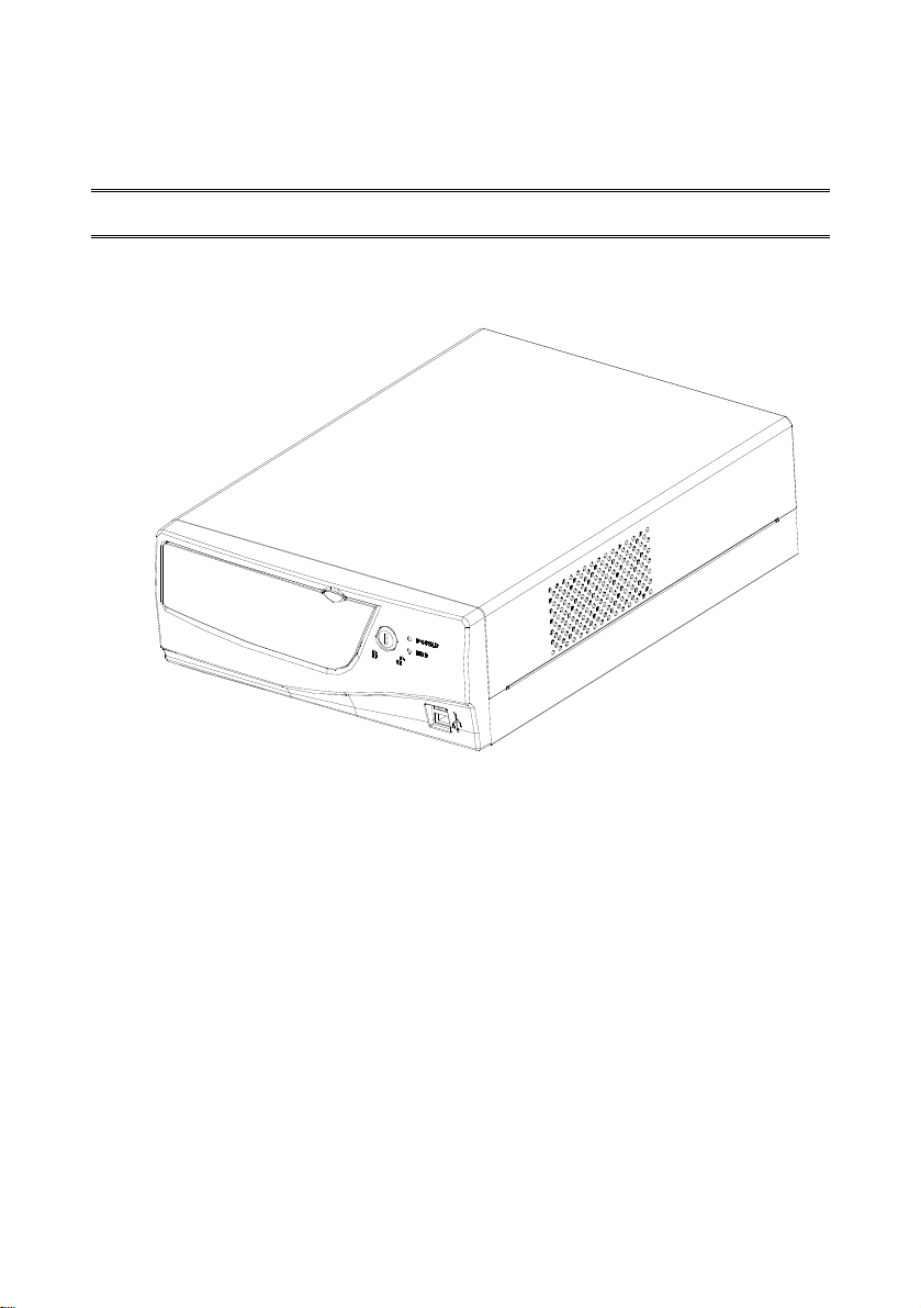
PPTT--11330000 PPOOSS TTeerrmmiinnaall
User’s Manual
V1.0
Page 2

P
RREEFFAACCE
P
E
CCooppyyrriigghhtt
This publication, including all photographs, illustrations and software, is
protected under international copyright laws, with all rights reserved.
Neither this manual, nor any of the material contained herein, may be
reproduced without written consent of the author.
Copyright 2003
Version 1.0
DDiissccllaaiimmeerr
The information in this document is subject to change without notice. The
manufacturer makes no representations or warranties with respect to the
contents hereof and specifically disclaims any implied warranties of
merchantability or fitness for any particular purpose. The manufacturer
reserves the right to revise this publication and to make changes from time
to time in the content hereof without obligation of the manufacturer to notify
any person of such revision or changes.
TTrraaddeemmaarrkk RReeccooggnniittiioonn
Microsoft, MS-DOS and Windows are registered trademarks of Microsoft
Corp.
Other product names used in this manual are the properties of their
respective owners and are acknowledged.
Page 3

FFeeddeerraall CCoommmmuunniiccaattiioonnss CCoommmmiissssiioonn ((FFCCCC))
This equipment has been tested and found to comply with the limits for a
Class a digital device, pursuant to Part 15 of the FCC Rules. These limits
are designed to provide reasonable protection against harmful interference
in a residential installation. This equipment generates, uses, and can
radiate radio frequency energy and, if not installed and used in accordance
with the instructions, may cause harmful interference to radio
communications. However, there is no guarantee that interference will not
occur in a particular installation. If this equipment does cause harmful
interference to radio or television reception, which can be determined by
turning the equipment off and on, the user is encouraged to try to correct
the interference by one or more of the following measures:
♦ Reorient or relocate the receiving antenna.
♦ Increase the separation between the equipment and the
receiver.
♦ Connect the equipment onto an outlet on a circuit different
from that to which the receiver is connected.
♦ Consult the dealer or an experienced radio/TV technician for
help.
Shielded interconnect cables and a shielded AC power cable must be
employed with this equipment to ensure compliance with the pertinent RF
emission limits governing this device. Changes or modifications not
expressly approved by the system's manufacturer could void the user's
authority to operate the equipment.
DDeeccllaarraattiioonn ooff CCoonnffoorrmmiittyy
This device complies with part 15 of the FCC rules. Operation is subject to
the following conditions:
♦ This device may not cause harmful interference, and
♦ This device must accept any interference received, including
interference that may cause undesired operation.
Page 4

AAbboouutt tthhiiss MMaannuuaall
The manual consists of the following sections:
♦ Chapter 1: Introducing the PT-1300: provides general
information on the POS Terminal, a packing list, and
illustrations of the POS Terminal components.
♦ Chapter 2: Setting Up the System: provides information on
attaching peripheral and optional devices.
♦ Chapter 3: Upgrading the PT-1300: provides instructions for
installing a CD-ROM drive, and installing or upgrading the
HDD, memory, and CPU. Instructions for installing an add-on
card are also provided.
♦ Appendix A: Specifications: provides detailed specifications
for the POS Terminal.
♦ Appendix B: Troubleshooting: gives troubleshooting
procedures for the POS Terminal.
♦ Appendix C: Jumper Settings: provides jumper settings for
the I/O PCB and shows the main board component layout.
7
Page 5

S
AAFFEETTYY
S
Before installing and using the PT-1300 POS Terminal, take note of the
following precautions:
♦ Read all instructions carefully.
♦ Do not place the unit on an unstable surface, cart, or stand.
♦ Do not block the slots and opening on the unit, which are
provided for ventilation.
♦ Only use the power source indicated on the marking label. If
you are not sure, contact your dealer or the Power Company.
♦ The unit uses a three-wire ground cable, which is equipped
with a third pin to ground the unit and prevent electric shock.
Do not defeat the purpose of this pin. If your outlet does not
support this kind of plug, contact your electrician to replace
your obsolete outlet.
♦ Do not place anything on the power cord. Place the power cord
where it will not be in the way of foot traffic.
♦ Follow all warnings and cautions in this manual and on the unit
case.
♦ Do not push objects in the ventilation slots as they may touch
high voltage components and result in shock and damage to
the components.
♦ When replacing parts, ensure that your service technician uses
parts specified by the manufacturer.
♦ When service or repairs have been done, ensure that the
service technician performs routine safety checks to verify that
the system is operating correctly.
♦ Avoid using the system near water, in direct sunlight, or near a
heating device.
♦ Cover the unit when not in use.
I
NNFFOORRMMAATTIIOON
I
N
♦ CB/UL/CUL/CE/FCC/VCCI/BSMI/CCC
Page 6

T
AABBLLEE OOFF
T
C
OONNTTEENNTTS
C
PREFACE I
Copyright.................................................................................................i
Disclaimer................................................................................................i
Trademark Recognition.........................................................................i
Federal Communications Commission (FCC) ....................................ii
Declaration of Conformity....................................................................ii
About this Manual................................................................................iii
Safety Information………………………............................................iv
A Tour of the PT-1300 ...............................................................................7
Package Contents................................................................................................ 8
Options................................................................................................................. 8
OUT LOOK..........................................................................................................9
Attaching Peripheral Devices ............................................................. 10
Connecting a PS/2 Keyboard and Mouse.........................................................11
Connecting a Printer.........................................................................................11
Connecting a VGA Monitor.............................................................................. 11
Connecting Serial Devices................................................................................ 12
Connecting a Cash Drawer...............................................................................12
Connecting USB Devices .................................................................................. 13
Connecting a Line-out Device and a Microphone...........................................13
Connecting to a LAN.........................................................................................14
Checking the Power Supply..............................................................................15
Turning the System On.....................................................................................16
Precautions...........................................................................................17
Before You Begin................................................................................. 18
Removing the Chassis Cover .............................................................. 19
Attaching the CD-ROM ......................................................................20
Replacing the Hard Disk Drive...........................................................23
Replacing Memory...............................................................................25
Installing a PCI Card ..........................................................................29
Installing a Cable Management Box.................................................. 32
Installing The customer display..........................................................34
PT-1300 POS Terminal Specifications............................................... 37
Locating a Problem..............................................................................39
Checking Cables and Connections.....................................................40
The Power-On Self Test ...................................................................... 40
General Hardware Problems..............................................................41
S
7
Page 7

Contacting Your Dealer ......................................................................42
Mainboard Components ..................................................................... 44
Mainboard Components.................................................................................... 45
Page 8

CChhaapptteerr 11:: IInnttrroodduucciinngg tthhee PPTT--11330000
AA TToouurr ooff tthhee PPTT--11330000
The PT-1300 provides you with a fast and accurate poin t-of-sales (POS)
solution for use in supermarkets, information kiosks, restaurants, and
other hospitality service areas. The PT-1300 POS Terminal’s mainboard
supports Intel Celeron-M processors 1.3 GHz. The mainboard supports
100 MHz frontside bus speeds and accommodates DDR SDRAM
memory up to 1024 MB.
The PT-1300 mainboard incorporates the innovative Intel 852GM chipset,
which delivers superior performance and scalability. The enhanced I/O
Controller Hub (ICH4) in the Intel 852GM chipset makes a direct
connection from the graphics and memory for fast access to peripherals
and higher system-level performance. Dual USB controllers provide 480
Mbps data transfer speed. ATA/100 support has been added to enable
fastest file/data transfers. The Intel 852GM chipset provides twice the
bandwidth of the PCI bus, as well as dedicated data paths to avoid PCI
bottlenecks.
The PT-1300 comes with the following I/O interfaces:
• One parallel ports (standard parallel port on main board)
• Four standard serial ports (COM1, COM2 with +5V and +12V
Bios Selector), PCB Rev: 0.3 COM3, COM4 PIN9 IS RI Pin,
PCB Rev: 1.2 COM3, COM4 PIN9 IS +5V.
• One Ethernet, 10/100/1000 BASE-T port
• One PS/2 keyboard port
• One PS/2 mouse port
• One VGA port
• Four USB ports
• One line-out
• One MIC-in
• Cash Drawer port
Page 9

PPaacckkaaggee CCoonntteennttss
The PT-1300 POS Terminal comes securely packaged in a sturdy
cardboard shipping carton. Upon receiving your PT-1300 POS Terminal,
open the carton and carefully remove the contents. If anything is missing
or damaged, please contact your dealer immediately. The shipping carton
should contain the following items:
• One PT-1300 POS Terminal
• One AC power cord
• Screws
• Support driver and utility CD-ROM or diskettes
• This user’s manual
OOppttiioonnss
• Customer display (CD7220/CD7220D/CD3160/CD3220)
• Monitor–9-inch CRT or 12-inch LCD
• POS printer
• Slim CDROM
• Standard FDD or Second HDD
• Real Box
8
Page 10
44
O
OOUUTT LLOOOOKK
O
UUTT LLOOOOKK
CD-ROM OR
FDD
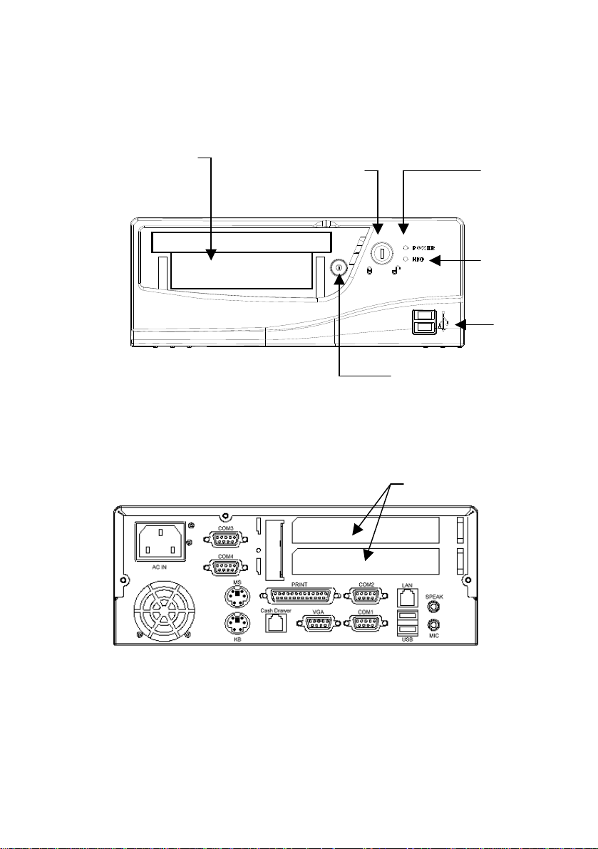
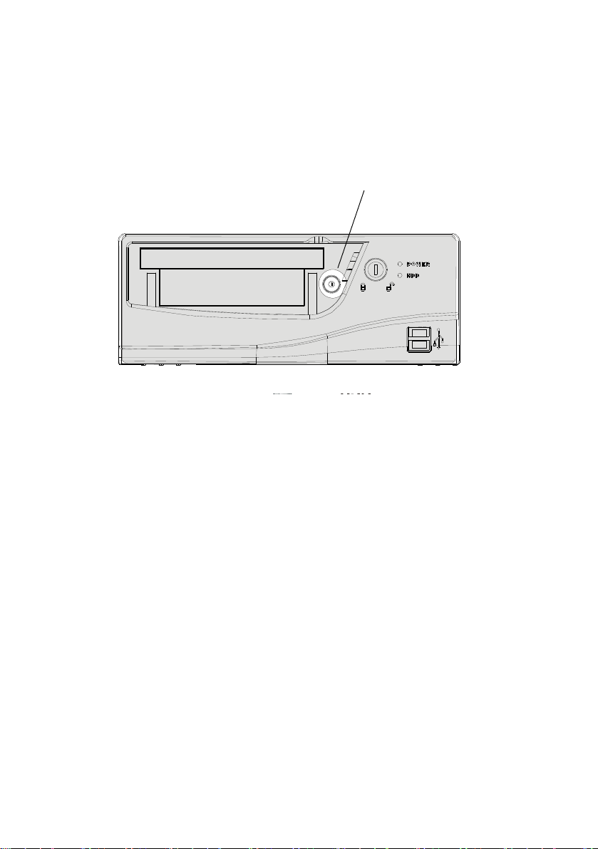
Figure 1 – PT-1300 POS Terminal front view
CD-ROM/FDD
Cover Release
Lock
Power
Status
LED
HDD
Status
LED
Front
USB
Power
Button
PCI card slot cover
Figure 2 – PT-1300 POS Terminal rear view
This concludes Chapter 1. The next chapter covers installation of the
system.
9
Page 11
CChhaapptteerr 22:: SSeettttiinngg UUpp tthhee SSyysstteemm
The PT-1300 accommodates standard peripheral devices such as a PS/2
mouse and keyboard,
AAttttaacchhiinngg PPeerriipphheerraall DDeevviicceess
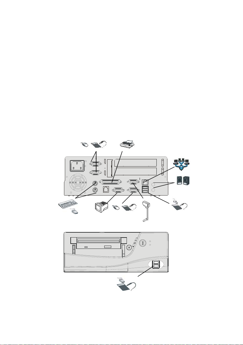
The PT-1300 POS Terminal supports many peripheral devices to expand
the functionality of the terminal:
Serial
Device
COM3
COM4
MOUSE
Re a rFront
PRINT
KB
Cash Drawer VGA COM1
Printer
LAN
COM2
USB
LINE OUT
MIC
External Speakers
and Microphone
Network
(LAN)
PS/2 Mouse
and keyboard
Figure 3 – Connecting peripheral devices
External
Monitor
Serial
Device
Customer
Display
USB
Compliant
Device
USB
Compliant
Device
USB
Compliant
Device
10
Page 12
44
C
CCoonnnneeccttiinngg aa PPSS//22 KKeeyybbooaarrdd aanndd MMoouussee
C
oonnnneeccttiinngg aa PPSS//22 KKeeyybbooaarrdd aanndd MMoouussee
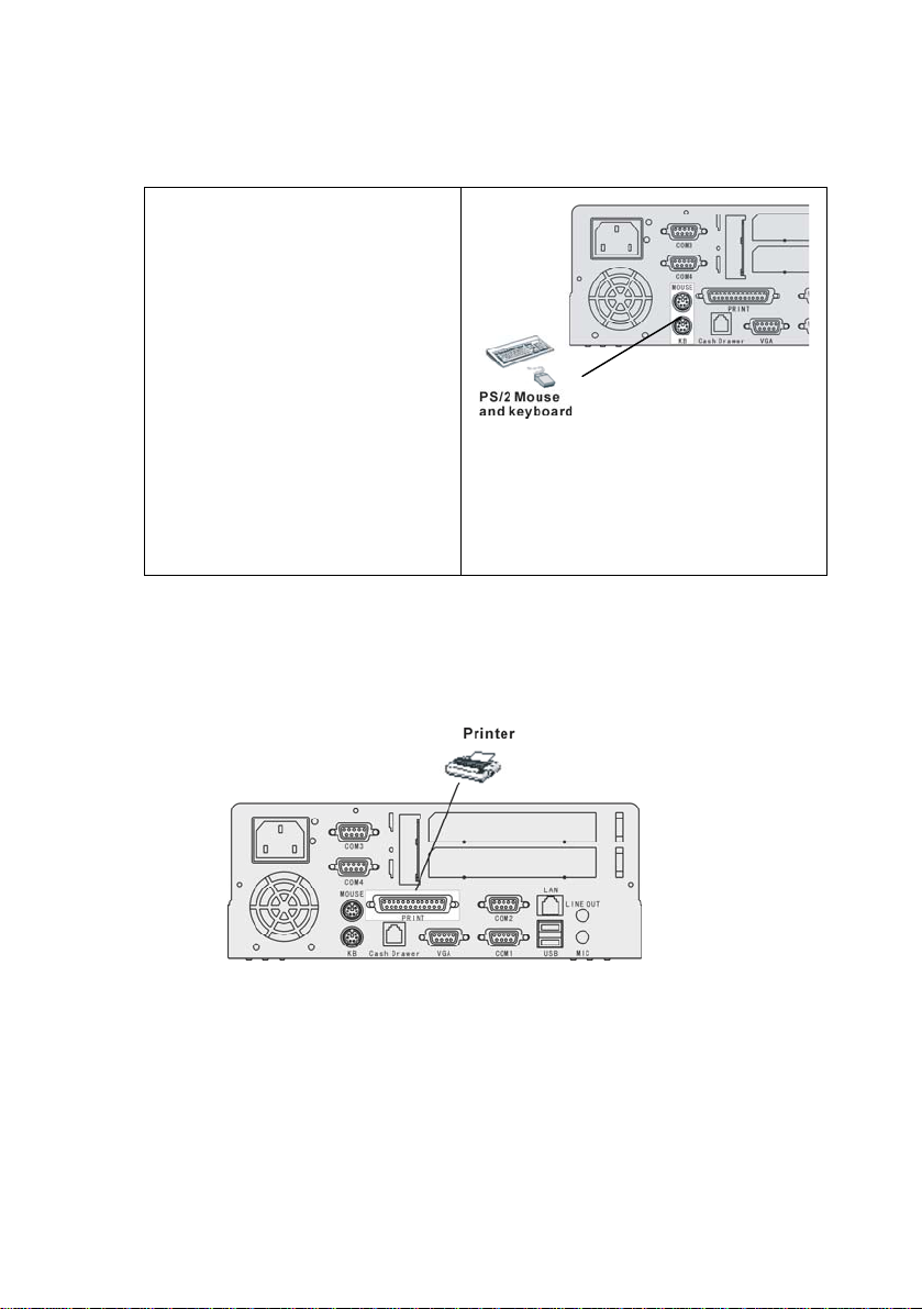
Connect a keyboard and mouse
Connect a keyboard and mouse
to the PS/2 keyboard and mouse
to the PS/2 keyboard and mouse
ports located at the rear of the
ports located at the rear of the
PT-1300.
PT-1300.
Note! The purple PS/2 port is
Note! The purple PS/2 port is
for the keyboard and the green
for the keyboard and the green
PS/2 port is for the mouse.
PS/2 port is for the mouse.
If your keyboard has an AT
If your keyboard has an AT
type connector, you must use
type connector, you must use
an adapter. Contact your
an adapter. Contact your
dealer for details.
dealer for details.
CCoonnnneeccttiinngg aa PPrriinntteerr
Connect a printer to the standard 25-pin D-type parallel connector on the I/O port
panel. Connect the optional POS printer to the RJ-45 jack COM3/COM4 on the
I/O port panel.
Figure 4 – Connecting a PS/2 mouse
or keyboard
Figure 5 – Connecting printer
CCoonnnneeccttiinngg aa VVGGAA MMoonniittoorr
You can connect a CRT or LCD panel to the VGA port.
11
Page 13
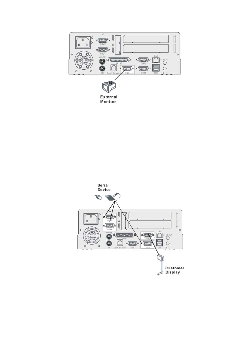
Figure 6 – Connecting an external monitor
CCoonnnneeccttiinngg SSeerriiaall DDeevviicceess
Connect serial devices to the 9-pin D-type serial ports on the I/O port
array. You can connect a CCD barcode scanner or Smart Card reader to
these ports. Connect a customer display to COM3.
Caution! These serial ports are voltage selectable and can cause
damage to external devices if not set up correctly. Refer
to Appendix C for serial port voltage settings via jumper.
Figure 7 – Connecting a serial device
CCoonnnneeccttiinngg aa CCaasshh DDrraawweerr
12
Page 14
44
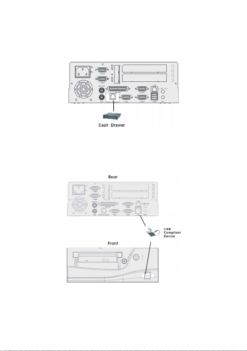
Connect the cash drawer RJ-11 connector to the RJ-11 port on the I/O
port array at the rear of the PT-1300.
Figure 8 – Connecting a cash drawer
CCoonnnneeccttiinngg UUSSBB DDeevviicceess
Connect USB devices to the USB ports on the I/O port array:
Figure 9 – Connecting USB devices
CCoonnnneeccttiinngg aa LLiinnee--oouutt DDeevviiccee aanndd aa MMiiccrroopphhoonnee
13
Page 15
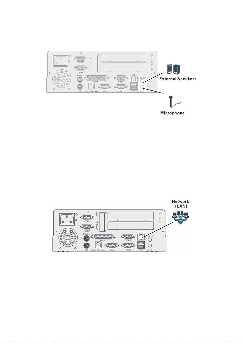
Connect speakers and a microphone to the line-out and MIC jacks on the
I/O port array:
Figure 10 – Connecting stereo speakers and a microphone
Note! You must install the audio driver before you can listen to audio output
with the speakers.
CCoonnnneeccttiinngg ttoo aa LLAANN
Connect a 10/100 Base-T Ethernet LAN to the RJ-45 jack on the I/O port
array:
Note: For EMC issue, Please add ferrite core 1.5 turns which component
is put on the package to the external LAN code.
14
Figure 11 – Connecting to the LAN
Page 16
AC
k
Starting the System
44
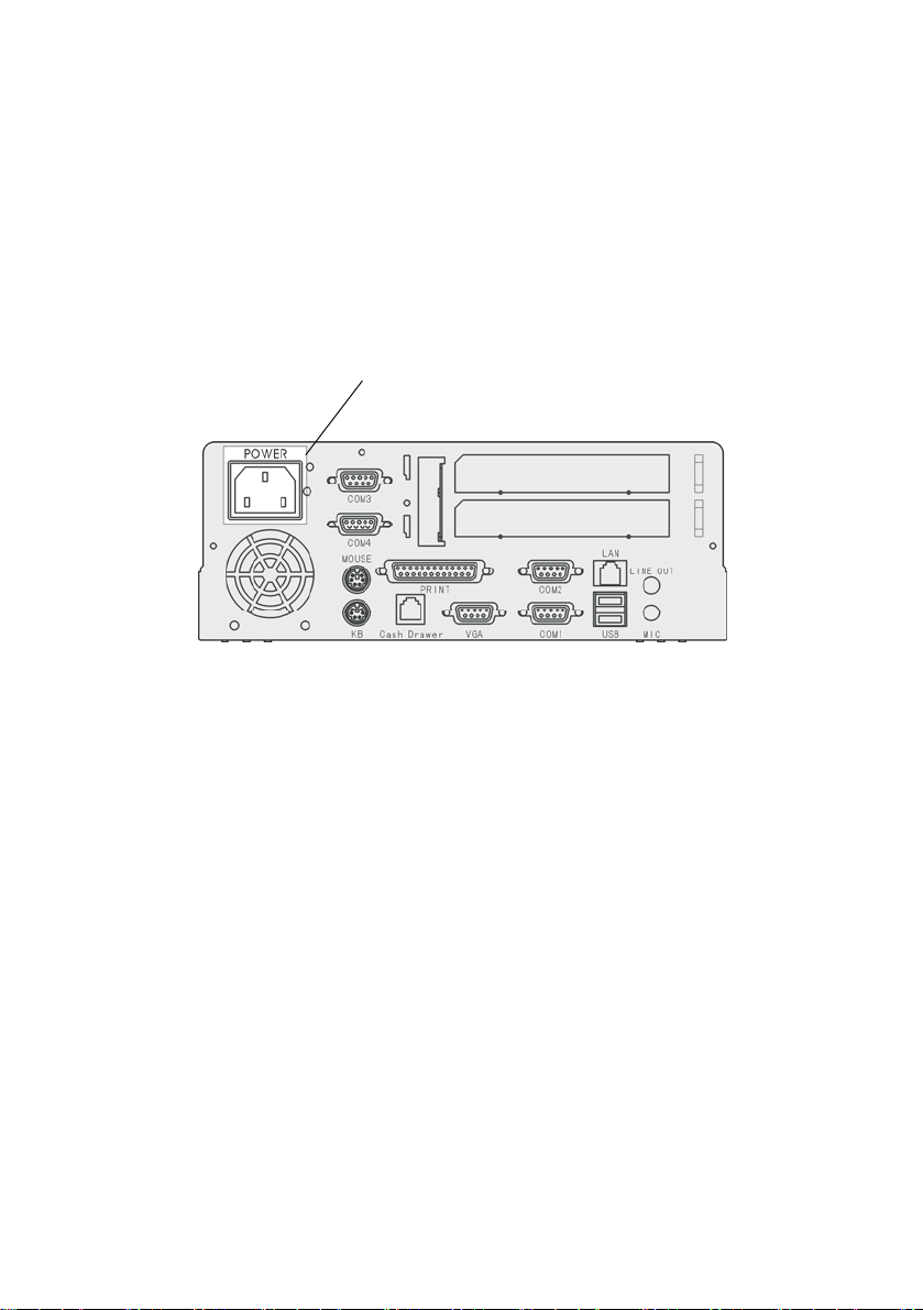
CChheecckkiinngg tthhee PPoowweerr SSuuppppllyy
The PT-1300 power supply automatically detects the power rating (115 or
230 volts) at your location.
power jac
This connector
Connect the power supply cable to the power jack on the I/O port array:
15
Page 17
TTuurrnniinngg tthhee SSyysstteemm OOnn
Press the power switch to turn the system on:
Figure 12 – Turning the system on
This concludes this chapter. The next chapter covers upgrade options.
Power switch
16
Page 18

CChhaapptteerr 33:: UUppggrraaddiinngg tthhee PPTT--11330000
This chapter covers upgrades to the PT-1300. You can attach a slim-type
CD-ROM drive and FDD, or upgrade the HDD, CPU, and memory.
PPrreeccaauuttiioonnss
POS Terminal components and electronic circuit boards can be damaged
by discharges of static electricity. Working on POS Terminals that are still
connected to a power supply can be extremely dangerous. Follow the
guidelines below to avoid damage to your POS Terminal or injury to
yourself.
• Always disconnect the unit from the power outlet.
• If available, wear a grounded wrist strap. Alternatively, discharge
any static electricity by touching the bare metal chassis of the unit
case, or the bare metal body of any other grounded appliance.
• Hold electronic circuit boards by the edges only. Do not touch the
components on the board unless it is necessary to do so. Do not
flex or stress the circuit board.
• Leave all components inside the static-proof packaging that they
ship with until they are ready for installation.
• After replacing optional devices, make sure all screws, springs, or
other small parts are in place and are not left loose inside the case.
Metallic parts or metal flakes can cause electrical shorts.
Page 19

BBeeffoorree YYoouu BBeeggiinn
Make sure you have a stable, clean working environment. Dust and dirt
can get into POS Terminal components and cause a malfunction. Use
containers to keep small components separated. Putting all small
components in a safe container keeps them from becoming lost. Adequate
lighting and proper tools can prevent you from accidentally damaging the
internal components. The procedures that follow require only a few tools,
including the following:
• A Philips screwdriver
• A flat-tipped screwdriver
• A set of jewelers screwdrivers
• A grounding strap
• An anti-static pad
Using your fingers can disconnect most of the electrical and mechanical
connections. It is recommended that you do not use needle-nosed pliers to
disconnect connectors as these can damage the soft metal or plastic parts
of the connectors.
Notes! 1. The arrows in the following procedures show the direction of
movement to remove/replace a device or component, or to turn a
screw or key to release a device.
2. All connectors are keyed to only attach one way.
3. Always use the correct screw size as indicated in the procedures.
18
Page 20
44
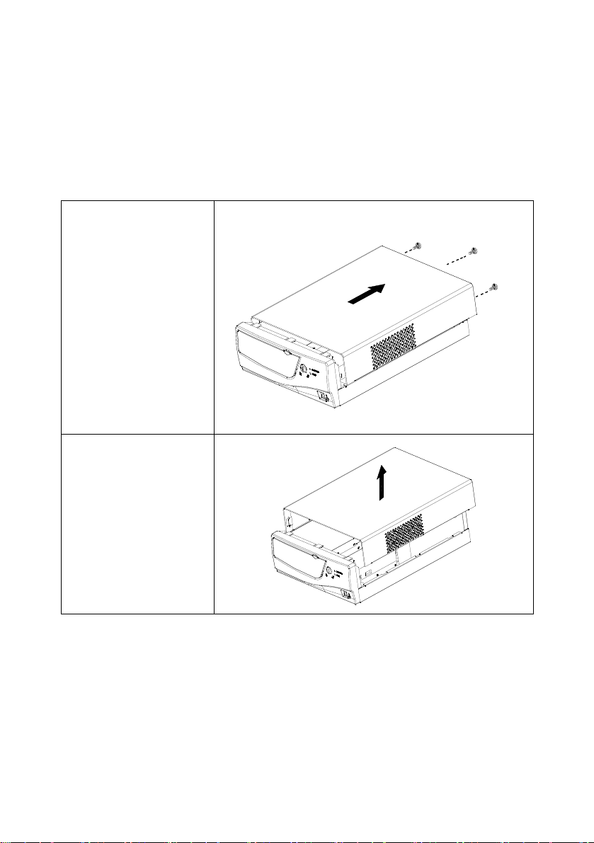
RReemmoovviinngg tthhee CChhaassssiiss CCoovveerr
Before Proceeding
• Disconnect the AC power cable.
• Disconnect all peripherals.
1. Remove the three
screws (6
securing the
chassis cover to
the chassis:
2. Slide the cover
towards the rear of
the PT-1300 and lift
up to remove the
cover.
¢ x 6)
19
Page 21
AAttttaacchhiinngg tthhee CCDD--RROOM
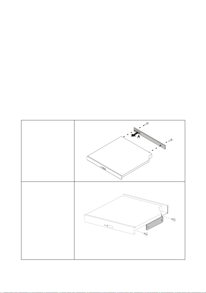
To install a CD-ROM drive in your PT-1300 POS Terminal, refer to the
following instructions.
Components Required
• Slim-type CD-ROM drive
• Control PCB
• CD-ROM plate
• (M2 x 4) screws x 2
• (M2 x 3) screws x 2
Before Proceeding
• Remove the chassis cover (see page 19).
1. Attach the control
PCB to the back of
the CD-ROM drive
and secure the
PCB to the CDROM drive with two
(M2 x 4) screws.
M
2. Secure the side
bracket to the
CDROM with two
(M2 X 3) screw
20
Page 22
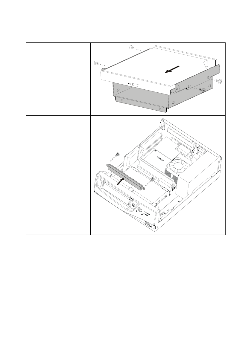
3. Slide the CD-ROM
into the CD-ROM
plate as shown by
the arrow and
secure the CDROM plate to the
CD-ROM with two
(M2 x 3) screws
and two (M2X6)
screws.
4. Remove the CDROM blanking
plate, if installed:
44
21
Page 23
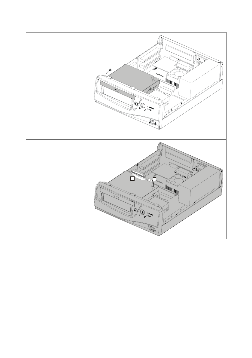
5. Slide the CD-ROM
assembly into place
and secure the
assembly to the
chassis with two
screws:
6. Connect the CDROM cable to the
CD-ROM drive
connector (A).
Connect a power
cable to the PCB
board power
connector (B).
A
B
22
Page 24
44
RReeppllaacciinngg tthhee HHaarrdd DDiisskk DDrriivvee
To upgrade the Hard Disk Drive (HDD) on your PT-1300 POS Terminal,
refer to the following.
Components Required
• Replacement HDD
• HDD cable
• HDD holding plate
• (6
¢ x 4) screws x 4
• (M3 x 4) screws x 2
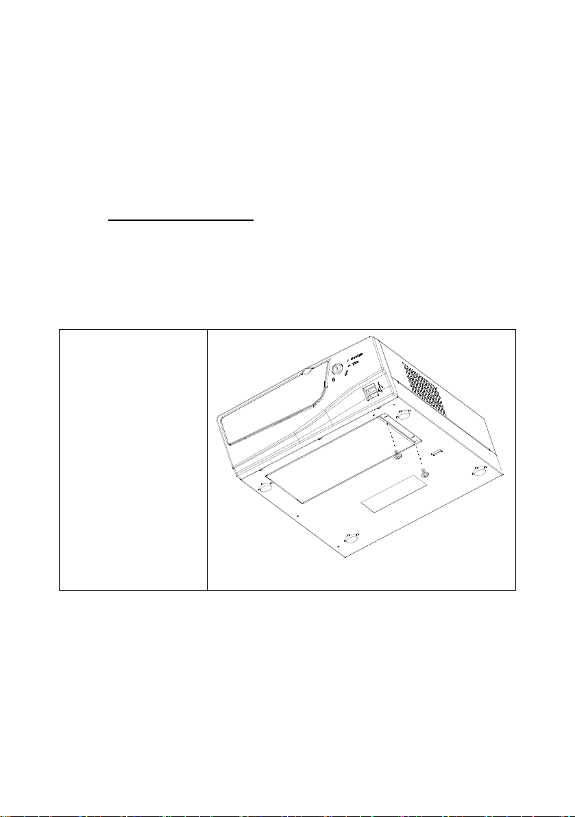
1. Remove the screw
(M3 x 4) securing
the HDD chassis:
23
Page 25
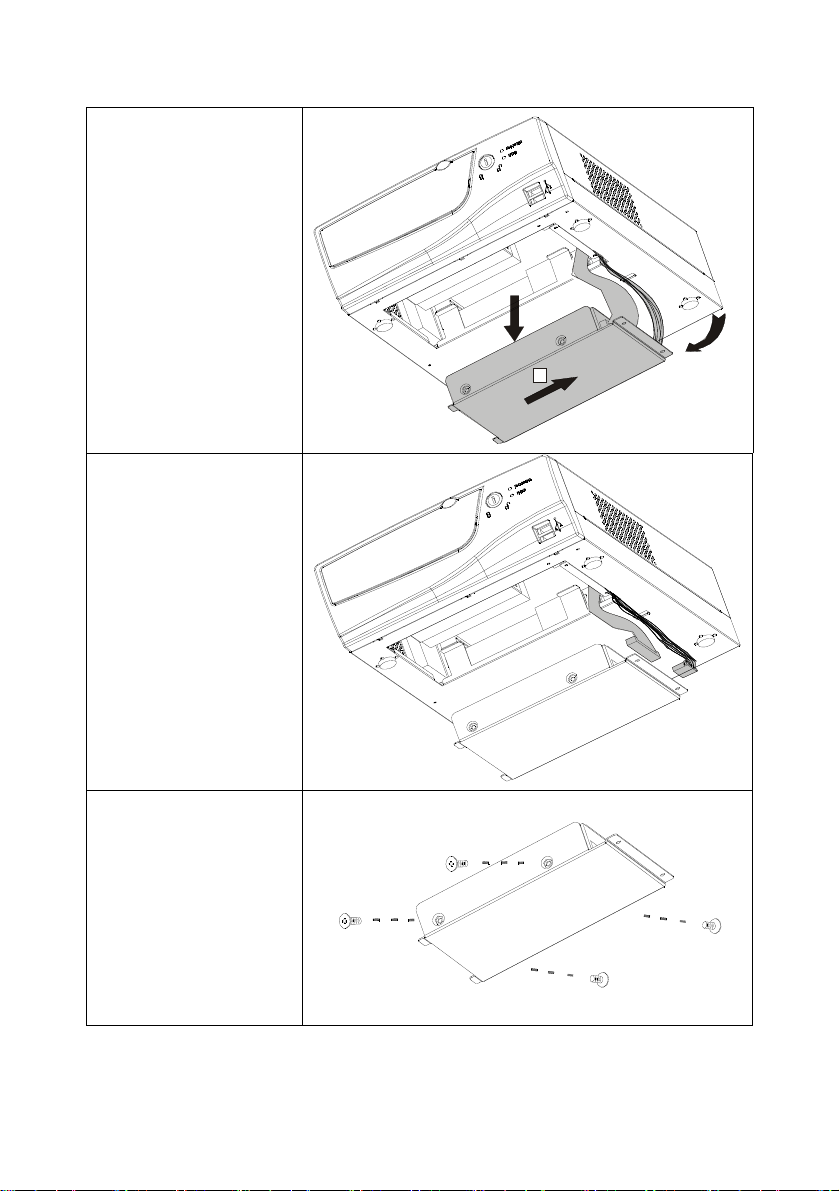
2. Slide the HDD
holding plate in the
direction of the
arrow to move it
from under the
HDD chassis clips
(B) and remove the
HDD assembly (C).
3. Disconnect the IDE
cable (B) and the
power cable (A)
C
A
B
B
A
4. Remove the four
screws (6
that secure the
HDD to the base
plate and remove
the plate
5. Replace the HDD
by reversing the
previous four steps.
24
¢ x 4)
Replace the chassis cover.
Page 26
44
RReeppllaacciinngg MMeemmoorryy
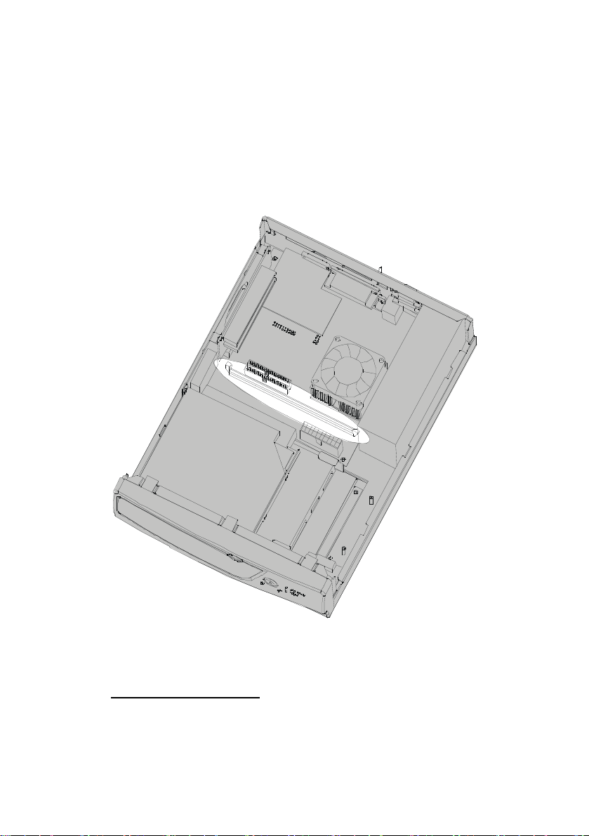
To upgrade the SDRAM memory on your PT-1300 POS Terminal
mainboard, refer to the following.
The following illustration shows memory installation components:
Figure 13 – PT-1300 memory slots
Components Required
Replacement memory
25
Page 27
Note! The PT-1300 mainboard accommodates 168-pin SDRAM chips. The
The mainboard accommodates two memory modules. You must install
Before Proceeding
• Remove the chassis cover (see page 19).
• Disconnect the HDD /CDROM/ FDD cable from the mainboard
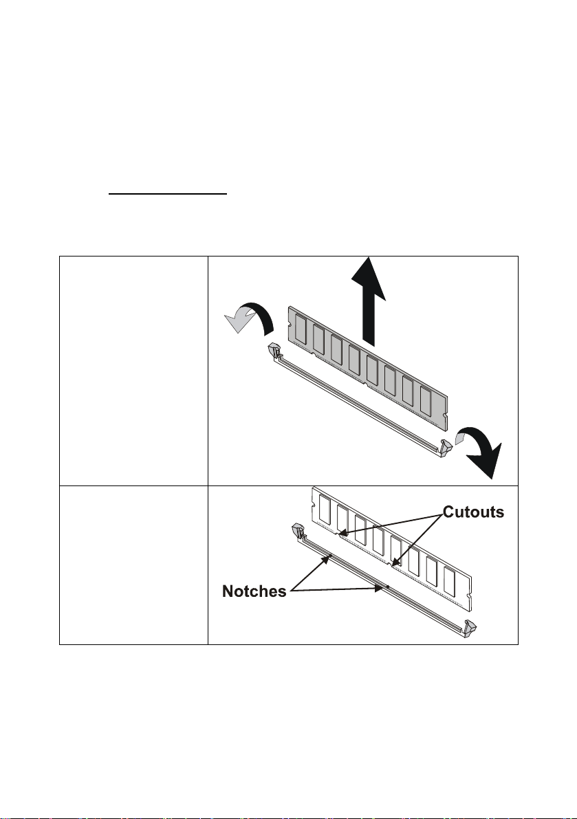
1. Push the latches on
each side of the
DIMM slot as
shown. The
memory module
pops up. Remove
the module.
memory bus runs at 66/100/133 MHz.
at least one module in any of the two slots. Each module can be
installed with up to 256 MB; total memory capacity is 512 MB.
IDE connector.
2. Check that the
cutouts on the
DIMM module edge
connector match
the notches in the
DIMM slot and
align the new
memory module
with the slot:
26
Page 28
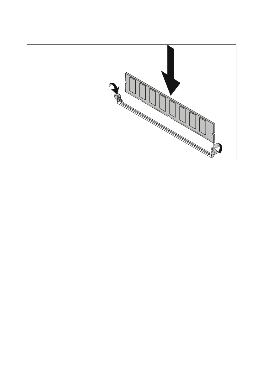
3. Install the DIMM
module into the slot
and press it firmly
down until it seats
correctly. The slot
latches are levered
upwards and latch
on to the edges of
the DIMM.
Reconnect the HDD IDE cable.
Replace the FDD/CD-ROM cable
Replace the chassis cover.
44
27
Page 29
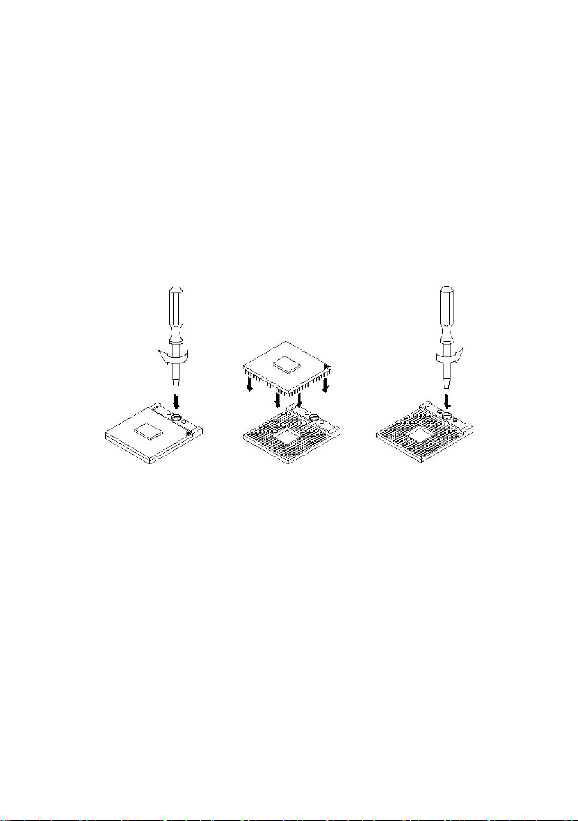
Installing the CPU
The PT-1300 board supports a Socket 479 processor socket for Intel® Pentium® M
or Celeron
®
M processors.
The processor socket comes with a screw to secure the processor. As shown in the
left picture below, loosen the screw first before inserting the processor. Place the
processor into the socket by making sure the notch on the corner of the CPU
corresponds with the notch on the inside of the socket. Once the processor has
slide into the socket, fasten the screw. Refer to the figures below.
NOTE: Ensure that the CPU heat sink and the CPU top surface are in total
contact to avoid CPU overheating problem that would cause your
system to hang or be unstable.
28
Page 30
44
I
IInnssttaalllliinngg aa PPCCII CCaarrdd
I
nnssttaalllliinngg aa PPCCII CCaarrdd
To install a PCI card to your PT-1300 POS Terminal mainboard, refer to
To install a PCI card to your PT-1300 POS Terminal mainboard, refer to
the following.
the following.
Note: Before installing an add-on card, check the documentation for the
Note: Before installing an add-on card, check the documentation for the
card carefully. If the card is not Plug and Play, you may have to
card carefully. If the card is not Plug and Play, you may have to
manually configure the card before installation.
manually configure the card before installation.
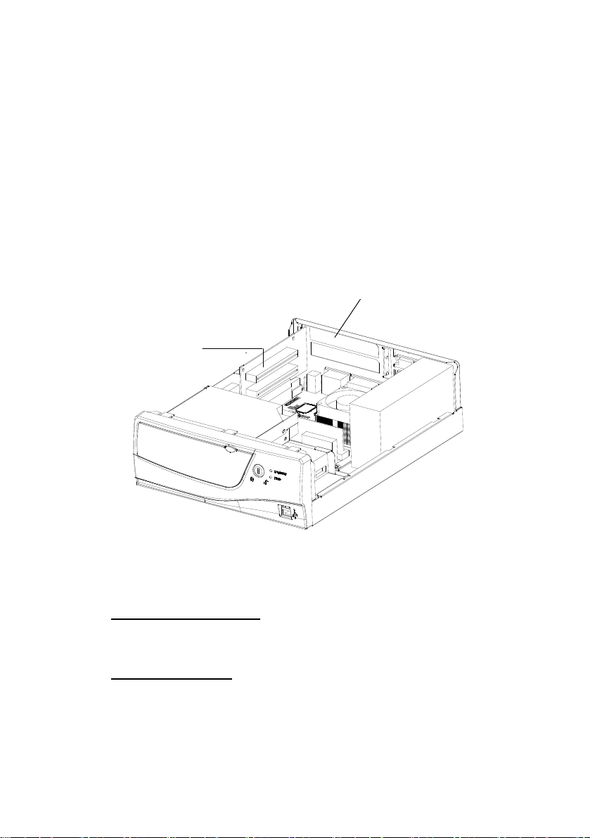
The following illustration shows add-on card installation components: The following illustration shows add-on card installation components:
PCI card slot
Blanking plate
Figure 14 – PT-1300 PCI slot
Components Required
32-bit PCI add on card
Before Proceeding
Remove the chassis cover (see page 19).
29
Page 31
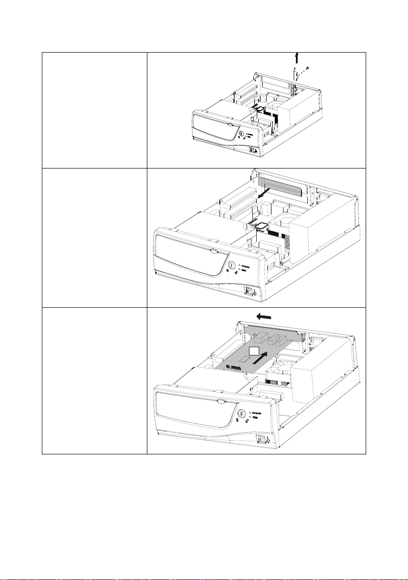
1. Remove the ADD
on card bracket
screw
2. Remove the
blanking plate from
the chassis.
3. Slide the PCI card
into place as
shown:
B
A
30
Page 32
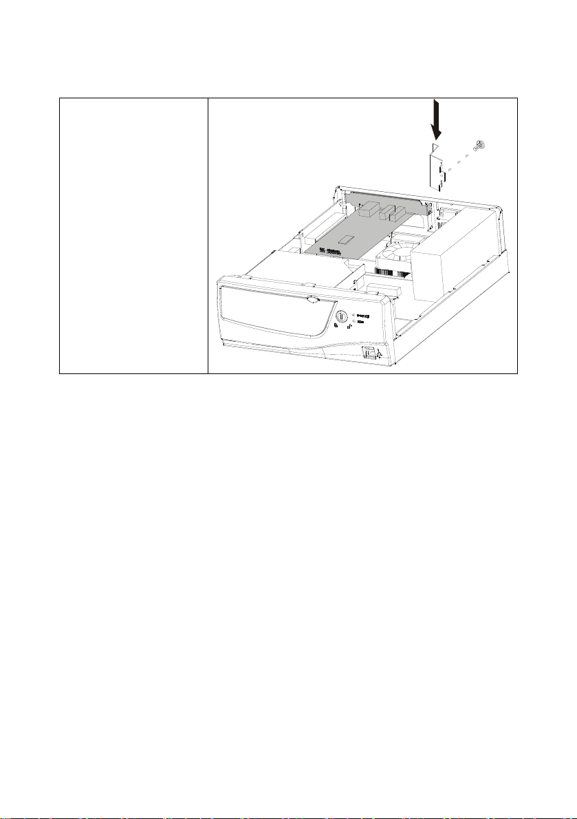
4. Line up the PCI
card bracket with
the bracket slot (A).
Insert the edge
connector of the
PCI card into the
expansion slot (B).
Replace the add on
card bracket screw.
Ensure that the
edge connector is
correctly seated in
the slot.
Replace the chassis cover.
44
31
Page 33
I
IInnssttaalllliinngg aa CCaabbllee MMaannaaggeemmeenntt BBooxx
I
nnssttaalllliinngg aa CCaabbllee MMaannaaggeemmeenntt BBooxx
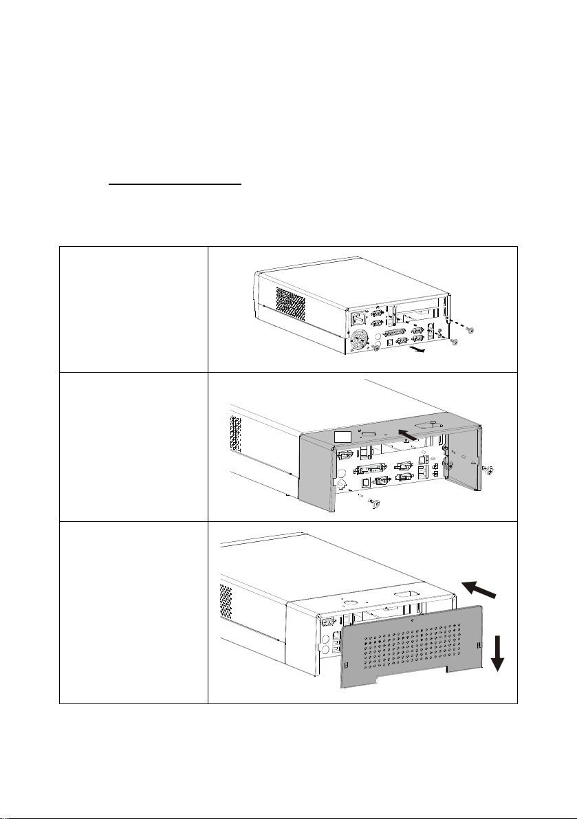
To add on the cable management box on your PT-1300 POS terminal refer
To add on the cable management box on your PT-1300 POS terminal refer
o the following
o the following
Components Required
Components Required
Cable management plate
Cable management back plate
1.Remove the three
screws (6
2. Secure the cable
management plate (A)
to the back side chassis
with three screws (B)
¢ x 4)
A
B
3 slide the back plate to
the cable management
plate (B)
A
B
32
Page 34
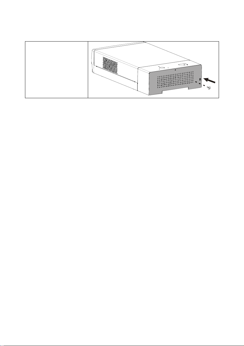
4 Secure the back plate
the with a screw
44
33
Page 35
I
IInnssttaalllliinngg tthhee ccuussttoommeerr ddiissppllaayy
I
nnssttaalllliinngg tthhee ccuussttoommeerr ddiissppllaayy
To add on the customer display ( CD-7220 ) on your PT-1300 POS
To add on the customer display ( CD-7220 ) on your PT-1300 POS
terminal refer o the following
terminal refer o the following
Components Required
Components Required
Cable management plate
Cable management back plate
Customer display CD-7220
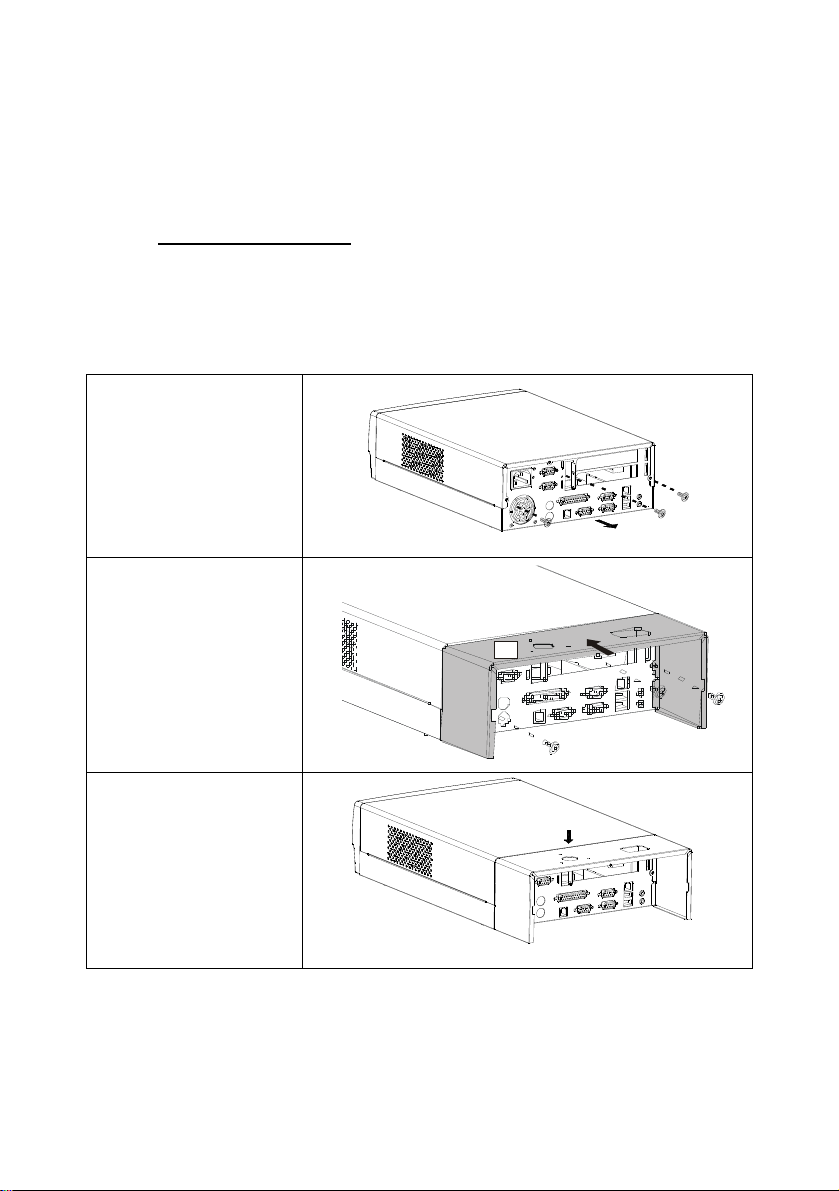
1.Remove the three
screws (6
2. Secure the cable
management plate (A)
to the back side chassis
with three screws (B)
¢ x 4)
A
B
3 remove the hole plate
34
Page 36
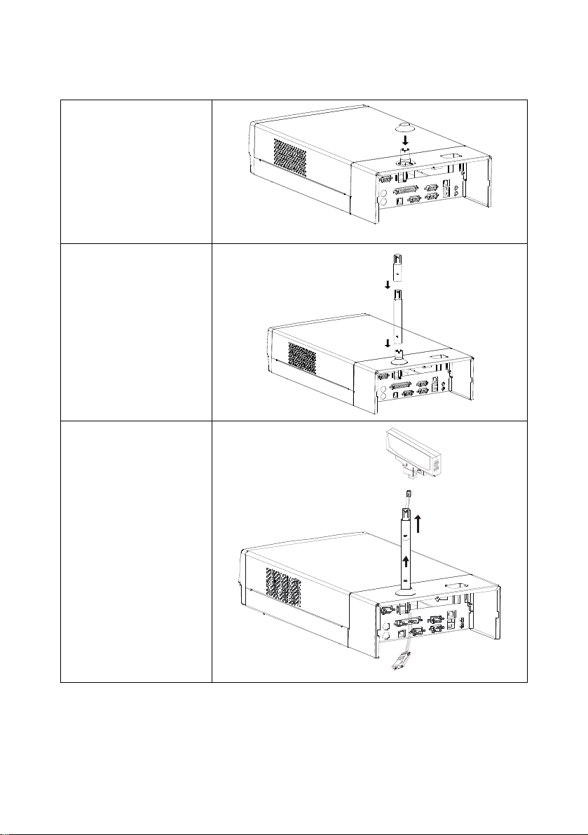
4 The display base
assembly into cable
management box
with three (M3X6)
screws
5 Lock the display
base cover into the
base
6 slide in the display
long or short pipe by
your need
7 RS-232 cable through
the display pipe from
bottom to up
8 The D-sub connector
plug into the COM 1 or
COM 2
44
35
Page 37
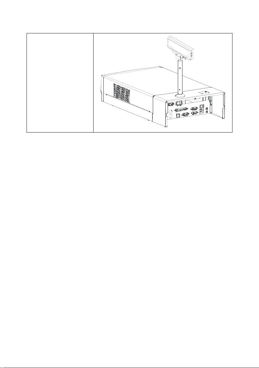
9. The 8-pin phone
jack plug into the
CD-7220 display.
10. The display lock
into the display
pipe
This concludes this chapter. The next chapter explains how to install
device drivers.
36
Page 38

AAppppeennddiixx AA:: SSppeecciiffiiccaattiioonnss
PPTT--11330000 PPOOSS TTeerrmmiinnaall SSppeecciiffiiccaattiioonnss
• Intel Celeron-M 1.3 GHz
• Intel 852GM + ICH4
• 100 MHz front side bus (FSB)
• 256 MB Memory, expandable to 1024 MB
• 3.5-inch IDE hard drive
• I/O Interfaces:
– One PS/2 keyboard port
– One PS/2 mouse port
– Four 9-pin serial ports
–
Four USB ports
– One LAN port
– 4 USB port
– One RJ6P cash drawer port
– One parallel port
– One microphone in
– One line-out
– One VGA port
– One 3P power jack
– Two expansion PCI slot
Note! If a slim FDD is installed, the PCI slot is unavailable.
• Options:
• Integrated AC ’97 codec, LAN, VGA, and ATA 100
• Support DOS, Windows XP/ME/2000/98
• Safety & EMI: CB, UL, CUL, CCC, CE, BSMI, FCC, VCCI
• Dimensions: 272 mm (L) x 296 mm (W) x 64 mm (H)
• Weight: 5.4 kg (including packaging)
Page 39

—Notes—
38
Page 40

AAppppeennddiixx BB:: TTrroouubblleesshhoooottiinngg
This appendix describes locating and solving problems that you may
encounter while using your POS Terminal.
LLooccaattiinngg aa PPrroobblleemm
Problems with your POS Terminal can be caused by something as minor
as an unplugged power cord—or as major as a damaged hard disk. The
information in this appendix is designed to help you find and solve minor
problems. If you try all the suggested solutions and you still have a
problem, make a list of what steps you have taken to correct the problem
and contact your dealer.
The problems that you will encounter can be divided into two basic
categories: hardware problems and software problems. Hardware
problems can be further divided into electrical and mechanical problems.
You will know you have a hardware problem if the screen is dark, the
POS Terminal cannot read the disk drives, or you get an error message
during the Power-On Self Test (POST).
Software errors can occur at several levels. The ROM BIOS and the
operating system can give error messages. On top of this, each application
software package has its own set of error messages. It is important to
determine whether the software error message you are getting is from the
application or the operating system. Once you know this, you can look in
the respective manual for a solution to the problem.
Page 41

CChheecckkiinngg CCaabblleess aanndd CCoonnnneeccttiioonnss
To check the power cables, and connections:
• Check the power outlet, the power cord, and any power switches
that may affect your POS Terminal. Check the wall outlet or
power strip with an item that you know is functioning properly (a
lamp or radio is a convenient item for checking the power). You
may also need to check the fuses and breakers in your electric box.
If a wall switch controls the outlet, make sure that the switch is on.
If your POS Terminal is plugged into a power strip with an on/off
switch, make sure the switch is on.
• With the POS Terminal’s power switched off, check all cable
connections. If the POS Terminal is connected to any peripheral
devices, look for loose or disconnected cables. If the POS
Terminal is too close to a wall, a cable connection may be loose
or the cables may be crimped.
Warning! Do not substitute cables for different devices (other than
the manufacturer recommended cables) even if they look
exactly alike. The wiring inside the cable may be different.
When you are certain that you have power available and all connections
are good, turn the POS Terminal on again. If the POS Terminal still does
not start, you may have a hardware problem.
TThhee PPoowweerr--OOnn SSeellff TTeesstt
The Power-On Self Test (POST) runs every time you turn on or reset the
POS Terminal. The POST checks memory, the mainboard, the display, the
keyboard, the disk drives, and other installed options.
A few seconds after you turn on your POS Te rminal, a copyright message
appears on your display screen. A memory test message appears next; as
the test continues, memory size increases until all installed memory is
tested. Normally, the only test routine visible on the screen will be the
memory te st.
40
Page 42

44
If failure is detected in an area other than the mainboard (such as the
keyboard or an adapter card), an error message is displayed on the screen
and testing is stopped.
If your system does not successfully complete the POST, but displays a
blank screen, emits a series of beeps, or displays an error code, consult
your dealer.
GGeenneerraall HHaarrddwwaarree PPrroobblleemmss
A few common hardware problems and suggested solutions are presented
in the table below:
Problem Solution
The display screen is dark. Adjust the screen brightness. (Refer to
the monitor user’s manual).
Make sure that the POS Terminal is
not in Suspend mode.
An incorrect date and time are
displayed.
The message:
“Invalid system disk,
Replace the disk, and then press
any key”
Appears during boot.
Correct the date and time using the
DOS DATE and TIME commands or
the options in the Setup Utility. (You
can also set the date and time in
Windows by double clicking the clock
on the task bar or in the control panel.)
If the date and time become incorrect
after a short time, your CMOS battery
may be depleted. Contact your dealer
to change the battery.
Check and make sure that you do not
have a non-bootable floppy diskette
inserted in your floppy drive. If your
FDD is empty, you may not have an
operating system installed on your
drive. Contact your dealer for support.
You hear irregular beeps during
operation of the POS Terminal and the
system halts.
The problem is beyond the scope of
this manual. Contact your dealer for
support.
41
Page 43

Problem Solution
An unidentified message is displayed. Reboot the POS Terminal and run the
BIOS Setup Utility. Confirm the Setup
Utility parameters. If the same
message is displayed after booting up
again, contact your dealer for support.
The system cannot access the CDROM/DVD-ROM drive.
You cannot operate the printer. Check the printer cable connection.
You can’t save data to disk. Ensure that the disk has been
You cannot use the mouse. Check the cable connection.
Check that a CD/DVD is properly
inserted in the drive.
Ensure that the printer power switch is
turned on.
Confirm that the printer is on-line.
formatted. Consult your operating
system manual for information on
formatting floppy diskettes.
The diskette is write-protected. Eject
the diskette, remove the write
protection, and try again.
The diskette if full. Try using another
diskette or free up some space on the
diskette.
The disk drive is not operating.
Contact your dealer for support.
Check the mouse with another
application to see if there is a software
incompatibility problem.
Check the mouse with another POS
Terminal to see if it works. If it doesn’t
operate on a different system, replace
the mouse.
CCoonnttaaccttiinngg YYoouurr DDeeaalleerr
If you still have a problem after reading the preceding sections, contact
42
Page 44

44
your dealer.
43
Page 45

AAppppeennddiixx CC:: JJuummppeerr SSeettttiinnggss
This appendix provides information on ju mper settings on the PT-1300
POS T erm inal.
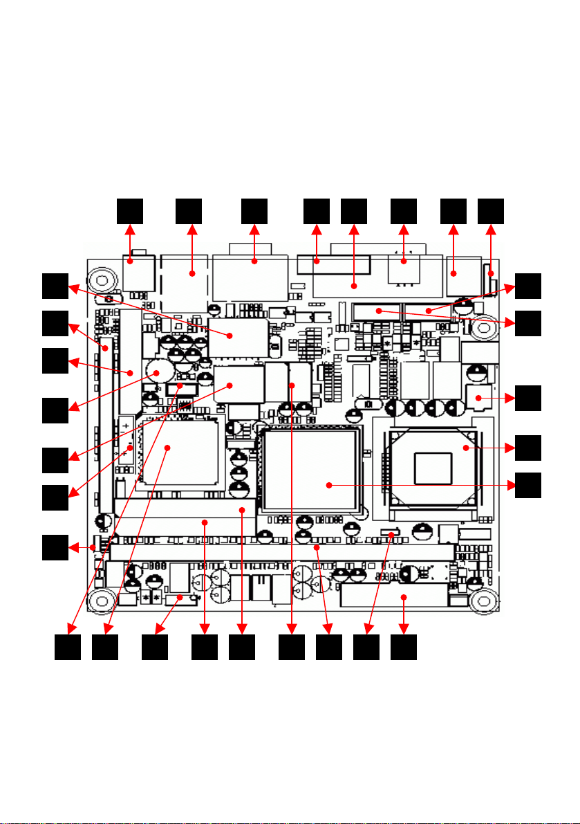
MMaaiinnbbooaarrdd CCoommppoonneennttss
The following table and illustration shows the mainboard components.
1 MSR
Jumper
6 COM1 (DL)
COM2 (UL)
ATX 2X2
11
POWER
16 FLOPPY
Connector
21 ATX 2X10
POWER
26 Secondly
IDE
Connector
2 Keyboard
Mouse
USB (DL
7
LAN (UL)
12 CPU 13 Intel
17 Buzzer 18 BIOS 19 Battery 20 CMOS
22 Cpu Type
Selector
27 Front
Panel PIN
3 CASH
Drawer
8 MIC (DL)
SPK (DL)
852GM
(NB)
23 DDR
SLOT
28 Intel ICH4
(SB)
4 PRINT 5 VGA
9 COM3 10 COM4
14 Realtek
8110SC
24 LVDS
Connector
29 Front USB
Port
15 Slim PCI
25 Primary
Connector
Slot
Jumper
IDE
Page 46
44
M
MMaaiinnbbooaarrdd CCoommppoonneennttss
M
aaiinnbbooaarrdd CCoommppoonneennttss
The following illustration shows the mainboard components: The following illustration shows the mainboard components:
7 6 5
14
15
16
17
18
19
8 4 3 2 1
9
10
11
12
13
20
29 28
45
27
Figure 15 – Mainboard components
2526
24 212223
Page 47
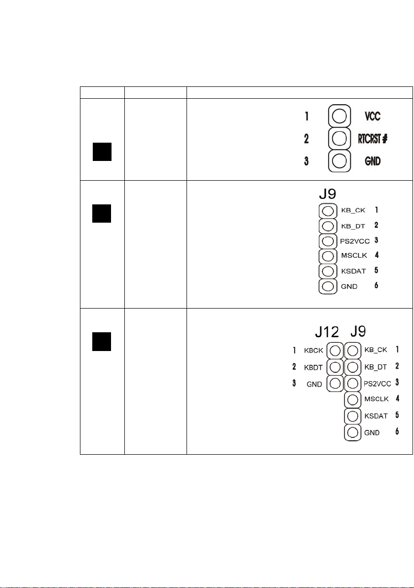
The following table shows the jumper settings:
Jumper Description Setting
J4
Clean
CMOS
1-2: Normal
2-4: clear CMOS
20
J9 For PCB
Rev: 0.3
1
Extend
KB/MS
J9 / J12 For PCB
Rev: 0.3For
1
MSR
adaptor
Default
1. KB_CK &
KBCK
CLOSE
2. KB_DT &
KBDT
CLOSE
.
46
Page 48
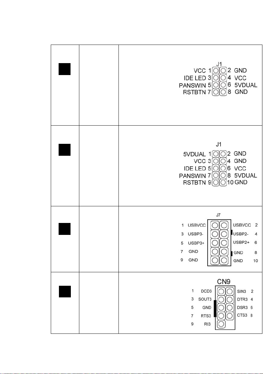
44
J1 For PCB
Rev: 0.3
27
Front Panel
J1 For PCB
Rev: 1.2
27
Front Panel
J7 USB 3/4
29
1-2, 3-4 for Power
LED
5-6 FOR IDE
LED
7-8 For Power
Button
9-10 For Reset
Button
1-2, 3-4 for Power
LED
5-6 FOR IDE
LED
7-8 For Power
Button
9-10 For Reset
Button
CN9 FOR PCB
Rev: 0.3
9
COM 3
47
Page 49
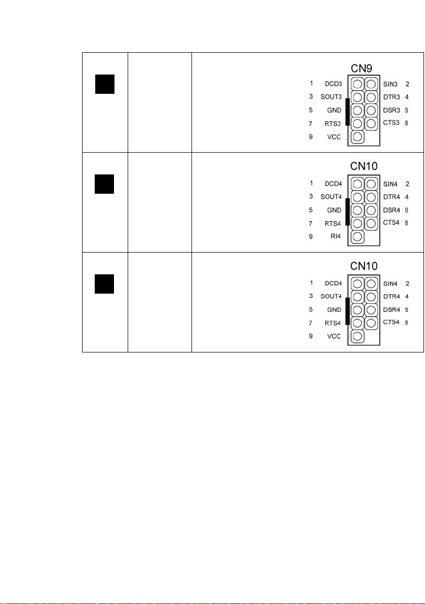
CN9 FOR PCB
Rev: 1.2
9
COM 3
CN10 FOR PCB
Rev: 0.3
10
COM 4
CN10 FOR PCB
Rev: 1.2
10
COM 4
48
 Loading...