

Page 1
Colibri 25
INSTRUCTION MANUAL
IMPORT ANT INFORMATION
GB
sure you understand them before using this unit. Retain these instructions for future
reference.
: Please read these instructions carefully and make
MANUEL D’INSTRUCTIONS
RENSEIGNEMENTSIMPORTANTS:
FR
atentivement les instructions et assurez--vous de les avoir comprises. Conservez
les instructions pour référence ultérieure.
Avant d’utilisercet ap pareil, veu illez lire
BETRIEBSANWEISUNG
WICHTIGE INFORMA TION:
DE
Geräts aufmerksam durch. Verwenden Sie es erst, wenn Sie sicher sind, daß Sie
alle Anweisungen verstanden haben und gut aufbewahren .
Lesen Sie diese Hinweise zur Handhabung des
MANUAL DE INSTRUCCIONES
INFORMACIÓN IMPORTANTE:
ES
asegúrese de entenderlas antes de utilizar esta aparato. Conservelas instrucciones para la referencia en el futuro.
Lea atentamente las instrucciones y
LIBRETTO D’ISTRUZIONI
INFORMAZIONI IMPORT ANTI
IT
istruzioni e prendere dimestichezza con il prodotto prima di usario. Mantenga
queste istruzioni per riferimento futuro.
: Siete pregati di leggere attentamente questo
HANDLEIDING
BELANGRIJKEIMPORTANTS:
NL
zeker van dat uze begrijpt alvorens de trimmer te gebruikenenbewaa rzevoor
toekomstige raadpleging.
Lees deze instructies zorgvuldig en wees er
530164500 1/1/04
Page 2
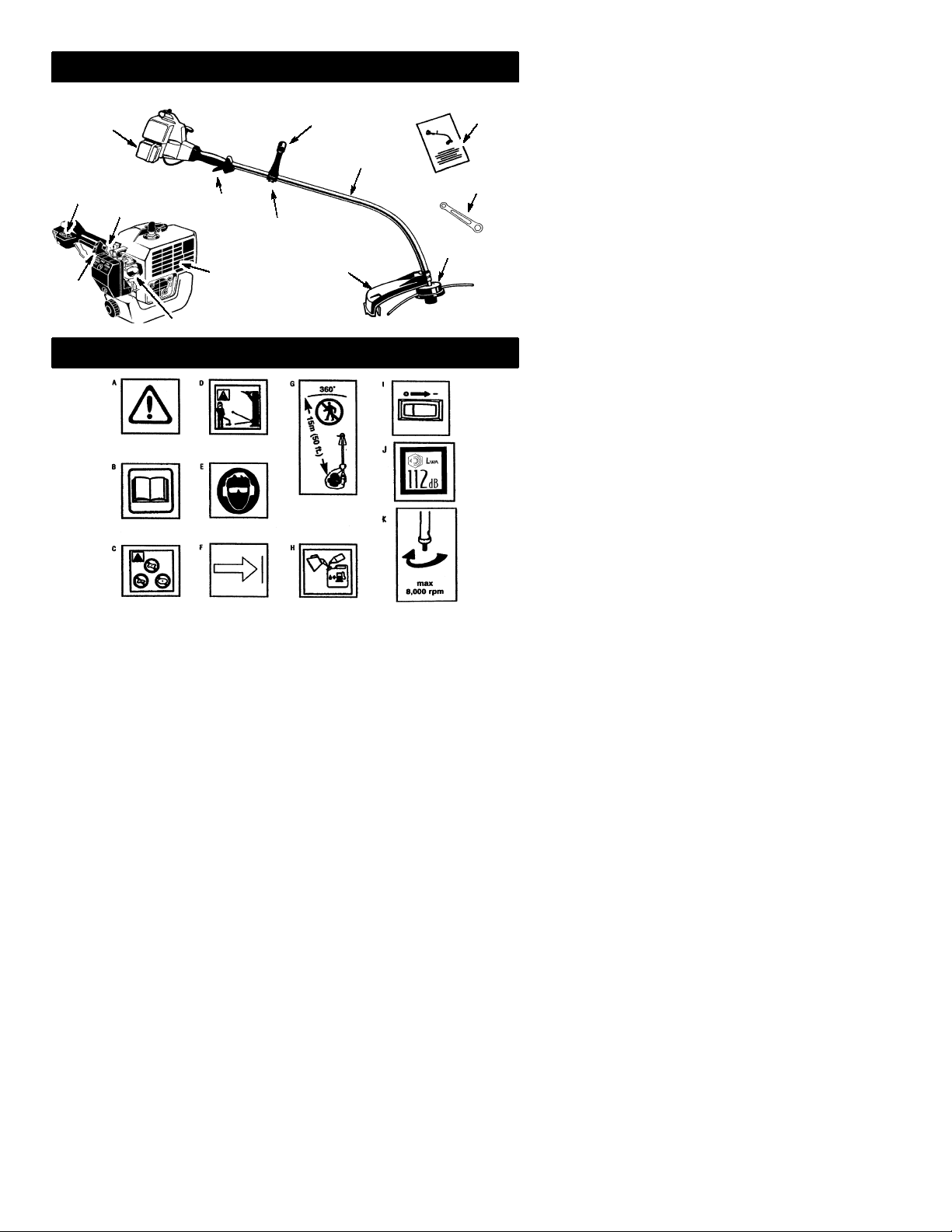
IDENTIFICATION (WHAT IS WHAT?)
Fuel tank
ON/OFF
Switch
Starter
Handle
Choke
Assist handle
Shaft
Throttle
Assist handle adjustment
Muffler
Primer Bulb
Shield
IDENTIFICATION OF SYMBOLS
Manual
Wrench
Trimmer head
A.
WARNING!
serious or even fatal injury.
B. Read and understand the instruction manual before using the trimmer.
C. Never use blades with this tool.
D.
WARNING!
injured. Always wear eye protection.
E. Always use:
Ear protection
Protective glasses or visor
F. Assist handle to be positioned only below the arrow.
G. The operatorofthe machinemust insure that noone comes within a15meterradius
while working.Whenseveral operatorsareworking withinthesame areaa safety dis-
tance of at least 15 meters must be observed.
H. Use unleadedor quality leaded petrol and two--stroke oil mixed at a ratio of 2.5%.
I. Engine ON/OFF Switch.
J. Sound power level
K. Max speed of outputaxle, rpm
Thistrimmercanbe dangerous!Careless or improperusecan cause
The trimmer line can throw objects violently. You can be blinded or
2
Page 3

SAFETY RULES
WARNING:
appliances, basic safety precautions should always be followed to reduce the risk of fire and
serious injury. Read andfollow all instructio ns.
This power unit can be dangerous! Operator is
responsible for following instructions andwarnings on unit and in manual. Read entire instruction manual before using unit! Be thoroughly familiarwiththecontrolsandthe properuse ofthe
unit. Restrict the use of this unit to persons who
read, understand, and follow instructions and
warnings on unit and in manual. Never allow
children to operate this unit.
INSTRUCTION
MANUAL
DANGER:
flailing devices. This unit is designed for line
trimmer use only.Use of any other accessories
or attachments will increase the risk of injury.
WARNING:
jects violently.Youand otherscan beblinded/
injured. Wear safety glasses and leg protection. Keep body parts clear of rotating line.
Safety Glasses or similar eye protection
Boots
Keepchildren, bystanders, and animals 15 meters away. If approached stop unit immediately.
If situations occur which are not covered in
this manual, usecare andgoodjudgement.If
youneedassistance,contactyourauthorized
service dealer.
OPERATORSAFETY
S Dress properly. Always wear safety
glasses or similar eyeprotection when operating, or performing maintenance, on
your unit (safety glasses are available).
Eye protection should be marked Z87.
S Always wear faceordust mask if operation
is dusty.
S Always wear heavy, long pants, long
sleeves, boots,andgloves. Wearingsafety
leg guards is recommended.
When using gardening
SAFETY INFORMATION
ON THE UNIT
Neveruseblades, wire, or
Trimmer line throws ob-
Hazard Zone
15 meters
S Always wear foot protection. Do not go
barefoot or wear sandals. Stay clear of
spinning line.
S Securehair aboveshoulderlength. Secure
or remove loose clothing or clothing with
loosely hanging ties, straps, tassels, etc.
They can be caught in moving parts.
S Being fully covered also helps protect you
from debris and pieces of toxic plants
thrown by spinning line.
S Stay Alert. Do not operate this unit when you
aretired,ill, upsetor und er theinflue nce ofalcoho l,drugs,or medicat ion. Watch wha tyou
are doing; use common sense.
S Wear hearing protection.
S Never start or run inside a closed room or
building. Breathing exhaust fumes can kill.
S Keep handles free of oil and fuel.
UNIT / MAINTENANCESAFETY
S Disconnect the spark plug before performing
maintenance except carburetor adjustments.
S Look for and replace damaged or loose
parts before each use. Look for and repair
fuelleaksbeforeuse.Keepingoodworking
condition.
S Replace trimmer head parts that are
chipped, cracked, broken, or damaged in
any other way beforeusing the unit.
S Maintain unit according to recommended
procedures. Keep cutting line at proper
length.
S Use only 2 mm diameter Partner! brand
line. Never use wire, rope, string, etc.
S Installrequiredshieldproperlybeforeusing
the unit. Use only specified trimmer head;
make sure it is properly installed and securely fastened.
S Make sure unit is assembled correctly as
shown in this manual.
S Make carburetor adjustments with lower
endsupportedto preventlinefromcontacting any object.
S Keepothers awaywhenmakingcarburetor
adjustments.
S Use only recommended Partner! acces-
sories andreplacement parts.
S Have all maintenance and service not ex-
plained in this manual performedby anauthorized service dealer.
FUEL SAFETY
S Mix and pourfuel outdoors.
S Keep away from sparks or flames.
S Use a container approvedfor fuel.
S Donotsmoke or allow smoking nearfuelor
the unit.
S Avoidspillingfu el oroil. Wipeupall fuel spills.
S Move at least 3 meters away from fueling
site before starting engine.
S Stop engine and allow to cool before re-
moving fuel cap.
S Always store gasoline in a container ap-
proved for flammable liquids.
3
Page 4
CUTTINGSAFETY
WARNING:
each use. Remove objects (rocks, broken
glass, nails, wire, etc.) which can be thrown
by or become entangled in line. Hard objects
can damagethetrimmer headandbe thrown
causing serious injury.
S Use only for trimming, scalping, mowing
andsweeping.Do not useforedging, pruning or hedge trimming.
S Keepfirm footingandbalance.Donotover-
reach.
S Keepall parts ofyour bodyawayfrommuf-
fler and spinning line. Keep engine below
waist level. Ahotmuffler cancauseserious
burns.
S Cut from your right to your left. Cutting on
leftsideof theshield will throwdebrisaway
from the operator.
S Use only in daylight or goodartificial light.
S Use only for jobs explained in this manual.
TRANSPORTINGAND STORAGE
S Allow theengineto cool; secure unit before
storing or transporting in vehicle.
S Empty fueltankbefore storing ortransport-
ingtheunit.Useupfuel leftinthecarburetor
by starting engine and letting it run until it
stops.
Inspect the area before
ASSEMBLY
S Storeunitand fuelinan areawherefuel va-
pors cannot reach sparks or open flames
from water heaters, electric motors or
switches, furnaces, etc.
S Storeunit so linelimiter cannotaccidentally
cause injury.Unitcanbe hungbythe shaft.
S Store the unit out of thereach of children
SPECIAL NOTICE:
tions throughprolongeduse of gasoline powered hand tools could cause blood vessel or
nerve damage in the fingers, hands, and
joints of people pronetocirculation disorders
or abnormal swellings. Prolongeduse in cold
weatherhasbeenlinked tobloodvesseldamagein otherwisehealthypeople. Ifsymptoms
occur such as numbness, pain, loss of
strength, change in skin color or texture, or
loss of feeling in the fingers, hands, orjoints,
discontinuetheuse ofthis toolandseekmedical attention. An anti-vibration system does
not guarantee the avoidance of these problems. Users who operate power tools on a
continual and regular basis must monitor
closely their physical conditionandthe condition of this tool.
Exposure to vibra-
WARNING:
ly assembled and all fasteners are secure.
Examine parts for damage. Do not usedamaged parts.
It is normal for the fuel filter to rattle in the
empty fuel tank.
Findingfueloroil residue onmufflerisnormal
due to carburetor adjustments and testing
done by the manufacturer.
Make sureunitisproper-
ADJUSTINGTHE HANDLE
WARNING:
handle,besure it remains above the safety label
and below the mark or arrow on the shaft.
1. Loosen wing nuton handle.
2. Rotate the handle on the shaft to an upright position; retightenwing nut.
Whena d justingth eassist
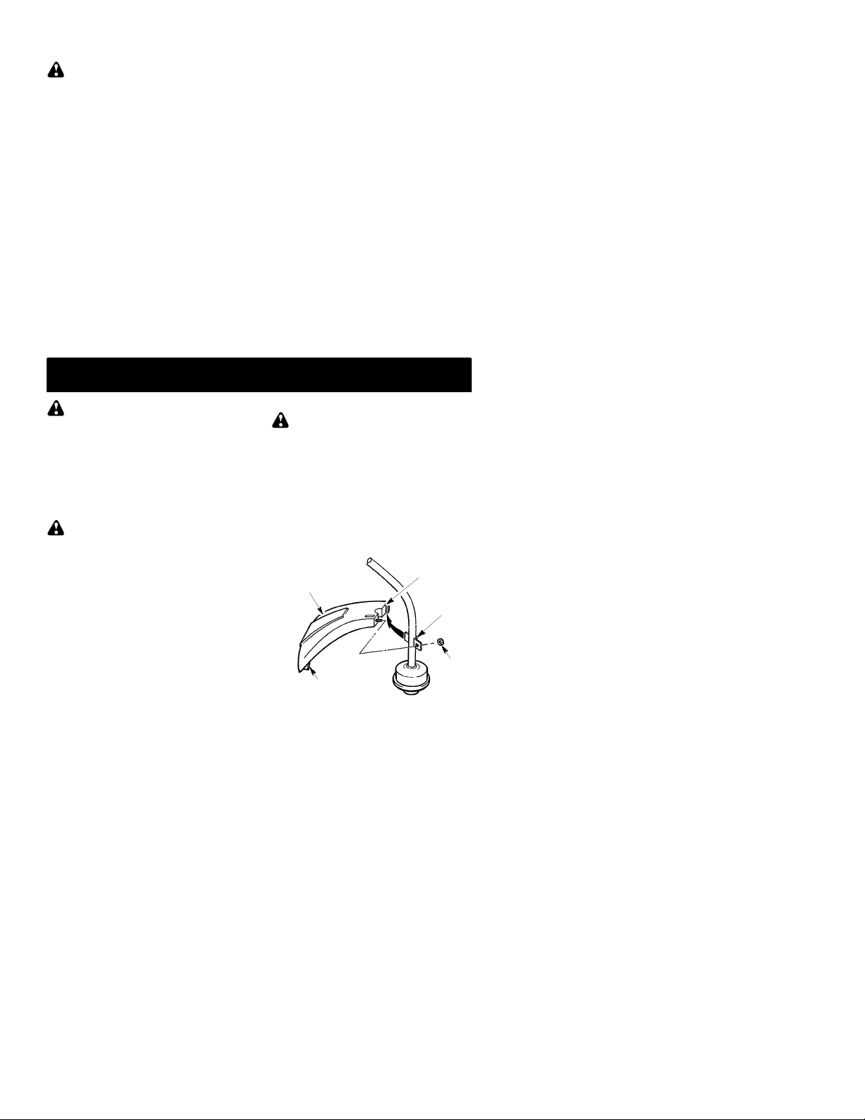
ATTACHING THE SHIELD
WARNING:
erly installed. The shield provides partial
protection from the risk of thrown objects to
theoperatorand others andis equippedwith
a line limiter which cuts excessline. Theline
limiter (on underside of shield) is sharp and
can cut you.
1. Remove nutfrom shield.
2. Insert bracket into slot on shield.
3. Pivot shielduntilboltpasses throughhole
in bracket.
4. Reinstall nut and tighten securely with
wrench (provided).
Shield
Line Limiter Blade
4
Theshieldmustbeprop-
Slot
Bracket
Nut
Page 5

OPERATION
WARNING:
information in the safety rules before you begin.Ifyoudo not understandthe safety rules,
do not attempt to fuel your unit. Contact an
authorized service dealer .
Be sure to read the fuel
FUELING ENGINE
WARNING:
when refueling.
This engine is certified to operate on un-
leaded gasoline. Before operation, gasoline
mustbemixedwitha goodquality2-cycle aircooled engine oil. We recommend Partner!
brand oil mixed at a ratio of 40:1 (2.5%). A
40:1ratiois obtained by mixing 5liters of unleaded gasoline with 0,125 liter of oil. DO
NOT USE automotive oil or boat oil. These
oils will cause engine damage. When mixing
fuel, follow instructions printed on oil container. Once oil is added to gasoline, shake container momentarily to assure that the fuel is
thoroughlymixed. Always readand followthe
safetyrulesrelatingto fuelbeforefueling your
unit.
IMPORTANT
Experience indicates that alcohol blended
fuels (called gasohol or using ethanol or
methanol)can attractmoisturewhichleadsto
separationand formationof acids duringstorage. Acidic gas can damage the fuel system
ofanengine whileinstorage.T oavoid engine
problems,emptythefuel system beforestoragefor 30 days or longer.Drainthegas tank,
starttheengineandletitrununtil thefuel lines
andcarburetorareempty.Use fresh fuelnext
season. Never use engine or carburetor
cleanerproductsinthe fueltank orpermanent
damage may occur.
HOW TO STOP YOUR UNIT
S To stop the engine, move the ON/OFF
switch to the OFF position.
Remove fuel cap slowly
HOW TO STARTYOUR UNIT
WARNING:
turnwhile starting theengine.Avoid any contact with the muffler. A hot muffler can cause
serious burns.
The trimmer head will
STARTING A COLD ENGINE (or a
warm engine after running out of fuel)
Starting Position
Starter Handle
Choke
Lever
Primer Bulb
1. Set unit on a flat surface.
2. Move ON/OFF switch totheONposition.
3. Slowly press the primer bulb 6 times.
4. Move choke lever to FULL CHOKE position.
5. Squeeze and hold trigger through all re-
maining steps.
6. Pull starter rope handle sharply until enginesoundsas if it is trying tostart, butdo
not pull rope more than 6 times.
7. As soon as enginesoundsas if it is trying
to start, move choke lever to HALF
CHOKE.
8. Pull starter ropesharply until engineruns,
but no more than 6 pulls. If the engine
doesn’t start after 6 pulls (at the HALF
CHOKE position), move the choke lever
to the FULL CHOKE position and press
theprimer bulb6 times.Squeeze andhold
thethrottletrigger andpull the starterrope
2moretimes.Movethe chokelevertothe
HALF CHOKE position and pull the starter rope until theengineruns,but no more
than 6 pulls.
NOTE:
probably flooded. Proceed toSTARTING
A FLOODED ENGINE.
9. Once theenginestarts, allow it to run 10
seconds, then move the choke lever to
OFF CHOKE. Allow theunit to run for 30
more secondsatOFFCHOKE beforereleasing the throttle trigger.
NOTE:
verin theOFF CHOKEposition,movethe
choke levertothe HALFCHOKEposition
andpull the ropeuntil engineruns, but no
more than 6 pulls.
STARTING A WARM ENGINE
1. Move ON/OFF switch totheONposition.
2. Move the choke lever to the HALF
CHOKE position.
3. Squeeze and hold the throttle trigger.
Keep throttle trigger fully squeezed until
the engine runs smoothly.
4. Pull starter ropesharply until engineruns,
but no more than 5 pulls.
5. Allow engine to run 15 seconds, then
movethechoke lever tothe OFFCHOKE
position.
If engine still doesn’t start, it is
If engine dies with the choke le-
Muffler
5
Page 6

If engine has not started, pull starter
NOTE:
rope5morepulls. Ifenginestill doesnotrun,it
is probably flooded.
ST ARTING A FLOODED ENGINE
Flooded engines can be started by placing
thechoke lever in theOFF CHOKE position;
then, pull the rope to clear the engine of excessfuel.Thiscouldrequirepullingthestarter
handle many times depending on how badly
the unit is flooded.
If the unit still doesn’t start, refer to TROUBLESHOOTING TABLE.
OPERATING INSTRUCTIONS
OPERA TINGPOSITION
ALWAYS WEAR:
Eye Protection
CUTTINGMETHODS
WARNING:
do not crowd the line when cutting around
hardobjects (rock, gravel, fence posts, etc.),
whichcandamagethetrimmer head,become
entangled in the line, or be thrown causing a
serious hazard.
S The tip of the line does the cutting. Youwill
achieve the best performance and minimum line wearbynotcrowdingtheline into
the cutting area. Theright andwrongways
are shown below.
Tip of the Line
Does The Cutting
Useminimum speedand
Line Crowded Into
Work Area
Long Pants
Heavy Shoes
Cut from your right to your left.
WARNING:
tion and hearing protection. Never lean over
the trimmer head. Rocks or debris can ricochet or be thrown into eyes and face and
cause blindness or other serious injury.
Do not run the engine at a higher speed than
necessary . The cutting line will cut ef ficiently
when the engine is run at less than full throttle.
At lower speeds, there is less engine noise and
vibration.Thecuttinglinewill lastlongera ndwill
be less likely to “weld” onto the spool.
Always release the throttle trigger and allow the
engine to return to idle speed when not cutting.
To stop engine:
S Release the throttle trigger.
S Move theON/OFFswitch to the OFF posi-
tion.
TRIMMERLINEADVANCE
Advancelinebytapping thebottomofthecuttingheadlightly onthe groundwhile engine is
running at full speed. The metal line limiter
blade attachedtothe guard will cut theline to
the proper length.
WARNING:
line.Other sizesandshapesof linewill notadvanceproperly andwill resultinimpropercuttinghead functionor cancause seriousinjury.
Do not use other materials such as wire,
string, rope, etc. Wire can break off during
cutting and become adangerousmissile that
can cause serious injury.
Always wear eyeprotec-
Use only 2 mm diameter
Right Wrong
S The line will easily remove grass and
weedsfrom aroundwalls, fences,treesand
flower beds, but it also can cut the tender
bark of trees or shrubs and scar fences.
S For trimming or scalping, use less than full
throttle to increase line life and decrease
head wear,especially:
S During light duty cutting.
S Near objects around which the line can-
wrap such as small posts, trees or fence
wire.
S Formowingor sweeping, usefull throttlefor
a good clean job.
TRIMMING -- Hold the bottom of the trimmer
head about 80 mm above the ground and at
anangle.Allow only the tip of theline to make
contact. Do not force trimmer line into work
area.
Trimming
3 in. (8 cm)
Above Ground
SCALPING -- The scalping technique removesunwantedvegetation.Hold thebottom
of the trimmer head about 80 mm above the
groundandatanangle.Allowthe tipof theline
to strike the ground around trees, posts,
monuments, etc. This technique increases
line wear.
Scalping
6
Page 7

MOWING -- Your trimmer is ideal for mowing
in places conventional lawn mowers cannot
reach. In the mowing position, keep the line
parallel to the ground. Avoid pressing the
head into the ground as this can scalp the
ground and damage the tool.
Mowing
MAINTENANCE
SWEEPING -- The fanningactionof therotating line can be used for a quick and easy
clean up. Keep the line parallel to and above
the surfaces being swept and move the tool
from side to side.
Sweeping
WARNING:
plug before performing maintenance except
for carburetor adjustments.
Disconnect the spark
CHECK FOR LOOSE
FASTENERSAND PARTS
S Spark Plug Boot
S Air Filter
S Housing Screws
S Assist Handle Screw
S Debris Shield
CHECK FOR DAMAGED OR
WORN PARTS
Contact an authorized service dealer for replacement of damaged or worn parts.
S ON/OFF Switch -- Ensure ON/OFF switch
functions properly by moving the switch to
the OFF position. Make sure engine stops;
then restart engine and continue.
S Fuel Tank -- Discontinue use of unit if fuel
tank shows signs of damage or leaks.
S Debris Shield -- Discontinue use of unit if
debris shield is damaged.
INSPECTAND CLEAN UNIT AND
LABELS
S After each use, inspect complete unit for
looseordamagedparts. Cleanthe unitand
labels using a dampclothwithamild detergent.
S Wipe off unit with a clean dry cloth.
CLEAN AIR FILTER
A dirty air filter decreases engine performance and increases fuel consumption and
harmful emissions. Always clean after every
5 hours of operation.
1. Clean the cover and the area around it to
keep dirt from falling into the carburetor
chamber when the cover is removed.
2. Remove parts as illustrated.
Donotcleanfilteringasoline orother
NOTE:
flammablesolventtoavoidcreatingafirehazard or producing harmful evaporative emissions.
3. Wash the filter in soap andwater.
4. Allow filter to dry.
5. Addafewdropsofoilto thefilter;squeeze
the filter to distribute oil.
6. Replace parts.
Air Filter
Screws
Air Filter
REPLACE SPARK PLUG
Replace the spark plug each year to ensure
the engine starts easier and runs better.Set
spark plug gap at 0,6 mm. Ignition timing is
fixed and nonadjustable.
1. Twist, then pull offspark plug boot.
2. Remove spark plugfrom cylinder anddis-
3. Replace with Champion RCJ-6Y spark
4. Reinstall the spark plug boot.
Cover
card.
plug and tighten securely with a 19 mm
socket wrench.
7
Page 8

SERVICE AND ADJUSTMENTS
REPLACINGTHELINE
1. Move the ON/OFF switch to the OFF
position.
2. Disconnect the spark plug lead wire.
3. Remove spoolbyfirmly pullingontapbutton. Clean entire surface of hub and
spool.Replacewith apre-woundspool,or
cut twolengthsof 4meters of2 mm diameter Partnerr brand line.
WARNING:
string,etc.,whichcanbreak offandbecome a
dangerous missile.
4. Insert ends of the line about 1cm intothe
small hole on the inside of spool.
Spool
Line exit holes
Hub
5. Wind the line evenly and tightly onto the
spool. Wind inthe direction of the arrows
found on the spool.
6. Push theline intothenotches, leaving 7-12 cm unwound.
7. Insert thelineintothethe exit holes in the
hubas shownin the illustration.
8. Align the notches with the line exit holes.
Never use wire, rope,
Small
Holes
Line in Notch
Line in Notch
9. Push spool into hub until it snaps into
place.
10. Pull the lines extendingoutsideof thehub
to release them from the notches.
CARBURETOR ADJUSTMENT
WARNING:
making idle speedadjustments. The trimmer
head will be spinning during this procedure.
Wearyourprotectiveequipmentandobserve
all safety precautions.
The carburetor has been carefully set at the
factory.Adjustments may benecessary ifyou
notice any of thefollowing conditions:
S Engine will not idle when the throttle is re-
leased.
Make adjustments with the unit supported so
the cutting attachment is off the ground and
will not make contact with any object. Hold
theunit byhandwhile runningandmakingadjustments. Keep all parts of your body away
from the cutting attachment and muffler.
Keep others away when
Idle Speed Adjustment
Allow engineto idle.Adjustspeed untilengine
runs without stalling (idle speed too slow).
S Turn idle speed screw clockwise to in-
creaseenginespeedif enginestalls ordies.
S Turnidle speedscrew counterclockwise to
decrease engine speed.
Idle Speed
Screw
Air Filter
Cover
Ifyou requirefurtherassistance orareunsure
about performing this procedure, contact an
authorized service dealer .
STORAGE
WARNING:
steps after each use:
S Allowenginetocoolbeforestoring ortrans-
porting.
S Store unit and fuel in awell ventilated area
where fuel vapors cannot reach sparks or
open flames from water heaters, electric
motors or switches, furnaces, etc.
S Empty fueltankbefore storing ortransport-
ing the unit.
S Store unit and fuel well out of the reach of
children.
S Store unit with all guards in place. Position
unit so that any sharp object cannot accidentally cause injury.
Perform the following
SEASONALSTORAGE
Prepareunit forstorageat endofseason or if
it will notbeused for 30 days or more.
If your unit is to bestoredfor a period of time:
S Clean the entire unit before lengthy stor-
age.
S Store in a clean dry area.
S Lightly oil external metal surfaces.
ENGINE
S Removespark plugand pour1 teaspoonof
40:1,2-cycleengineoil (air cooled) through
the spark plug opening. Slowly pull the
starter rope 8 to 10 times to distribute oil.
S Replacesparkplugwithnewoneofrecom-
mended type and heat range.
8
Page 9

S Clean air filter.
S Check entire unit for loose screws, nuts,
and bolts. Replace any damaged, broken,
or worn parts.
S At the beginning of the next season, use
only freshfuel havingthepropergasolineto
oil ratio.
OTHER
S Do not store gasoline from one season to
another.
S Replaceyourgasoline canifit startstorust.
TROUBLESHOOTING T ABLE
WARNING:
recommended remedies below except remedies that require operation of the unit.
Always stopunit anddisconnect sparkplugbeforeperformingall ofthe
TROUBLE CAUSE REMEDY
Enginewill not
start.
Enginewill
not idle
properly.
Enginewill not
accelerate,
lacks power,
or dies under
a load.
Engine
smokes
excessively.
Engine runs
hot.
1. ON/OFF switch in OFF
position.
2. Engine flooded.
3. Fuel tank empty.
4. Spark plug not firing.
5. Fuel not reaching
carburetor.
6. Carburetor requires
adjustment.
1. Carburetor requires
adjustment.
2. Crankshaft seals worn.
3. Compression low.
1. Air filter dirty.
2. Spark plug fouled.
3. Carburetor requires
adjustment.
4. Carbon build-up on
muffler outlet screen.
5. Compression low.
1. Choke partially on.
2. Fuel mixture incorrect.
3. Air filter dirty.
4. Carburetor requires
adjustment.
1. Fuel mixture incorrect.
2. Spark plug incorrect.
3. Carburetorrequires
adjustment.
4. Carbon build-up on
muffler outlet screen.
1. Move ON/OFF switch to ON position.
2. See “Starting a Flooded Engine” in
Operation Section.
3. Fill tank with correct fuel mixture.
4. Install new spark plug.
5. Check for dirty fuel filter; replace.
Check for kinked or split fuel line;
repair or replace.
6. Contact an authorized service dealer.
1. See “Carburetor Adjustment” in
Service and Adjustments Section.
2. Contact an authorized service dealer.
3. Contact an authorized service dealer.
1. Clean or replace air filter.
2. Clean or replace plug
and regap.
3. Contact an authorized service dealer.
4. Contact an authorized service dealer.
5. Contact an authorized service dealer.
1. Adjust choke.
2. Empty fuel tank andrefill with
correct fuel mixture.
3. Clean or replace air filter.
4. Contact an authorized service dealer.
1. Empty fuel tank andrefill with
correct fuel mixture.
2. Replace with correct spark plug.
3. Contact an authorized service dealer.
4. Contact an authorized service dealer.
9
Page 10

DECLARATION OF CONFORMITY
relating to 2000/14/EC
EC Declaration of Conformity relating to 2000/14/EC
We, Electrolux Home Products,Inc., Texarkana, TX, 75501, USA, Tél. : +1 903 223
4100,declare undersole responsibility thatthe Partnermodel Colibri25 grass trimmer
was assessed in accordance with Annex V of the DIRECTIVE and from serial numbers
2003--210N00001 and onwards, conforms to the provisions of the DIRECTIVE. The
cuttingwidthis 431 mm. Themeasuredsound poweris 108dB andthe guaranteedsound
power is 112 dB.
Texarkana 03--07--29
Michael S. Bounds, Director
Product Safety and Standards
DECLARATION OF CONFORMITY
relating to 98/37/EC
EC Declaration of Conformity (Directive 98/37/EC,Annex II, A) (Only applies to
Europe)
We, Electrolux Home Products, Inc., Texarkana,TX, 75501, USA, Tél. : +1 903 223
4100,Declare under sole responsibility that thePartnermodel Colibri 25 grasstrimmer
from serial numbers 2003--210N00001 and onwards, follows the provisions of the
DIRECTIVES: 98/37/EC (machinery) and 89/336/EEC (electromagnetic compatibility),
including amendments and is in conformity with the following standards: EN 292--2, EN
ISO 11806:1997and CISPR 12.
SMP, TheSwedishMachinery TestingInstitute, Fyrisborgsgatan3 S--754 50Uppsala,
Sweden, has carried out voluntary type approval. The certificate(s) are numbered:
SEC/97/552.
Texarkana 03--07--29
Michael S. Bounds, Director
Product Safety and Standards
10
Page 11

TECHNICAL DATA SHEET
M
ODEL: Colibri 25
ENGINE
Displacement, cm
Maximum enginepower, measured in
accordance with ISO 8893, kW 0,7
ENGINE ROTATIONALSPEEDS
At maximum engine power 8000
Recommended maximum speed 8000
Recommended speed idling 4000
FUEL AND LUBRICATION SYSTEM
Fuel tank volume capacity, cm
Fuel consumption at maximum engine power,
measured in accordance with ISO 8893,g/h 407
Specified fuel consumption at max. enginepower,
measured in accordance with ISO 8893,g/kWh 768
WEIGHT
Without cutting attachment or shield, empty tank, kg 3,7
CUTTING ATTACHMENT
Cutting head assembly, part number #952715588
NOISE LEVELS (Octave Band Analysis 100--10000hz 1/3 Octave)
SOUND PRESSURE LEVELSmeasuredin accordance with ISO 7917
Idling, dB(A) 78
Racing, dB (A) 96
SOUND POWER LEVELS measured in accordance with ISO 10884
Idling. dB(A) 91
Racing, dB(A) 106
VIBRATION LEVELS measured in accordance with ISO 7916
FRONT HANDLE
Idling, m/s
Racing, m/s
REAR HANDLE
Idling, m/s
Racing, m/s
YEAR OF CONSTRUCTION: 2004
MANUFACTURER’S ADDRESS: Electrolux Home Products, Inc.
3
3
2
2
2
2
250 Bobby Jones Expressway
Augusta, GA 30907
25
340
3,0
4,8
7,4
11,3
11
 Loading...