

Page 1
CD-70 USB Display
User Manual
Page 2

2
CONTENTS
CHAPTER 1 SAFETY �������������������������������������������������������������������3
CHAPTER 2 INTRODUCTION ������������������������������������������������������� 5
CHAPTER 3 INSTALLATION ���������������������������������������������������������7
CHAPTER 4 MOUNTING ������������������������������������������������������������ 10
CHAPTER 5 OPERATION ����������������������������������������������������������11
CHAPTER 6 TECHNICAL SUPPORT ������������������������������������������16
Page 3

3
CHAPTER 1
SAFETY
PRECAUTIONS
Follow all warnings, precautions and maintenance as recommended in this user manual to maximize the life
of your unit and prevent risks to user safety. See the Safety & Maintenance chapter for more information.
This manual contains information that is important for the proper setup and maintenance of the unit. Before
setting up and powering on your new USB display, read through this manual, especially the Installation,
Mounting, and Operation chapters.
This manual explains the procedures for operating and maintaining the USB display.
To ensure the proper use and optimum performance of this device, read this manual thoroughly.
FCC STATEMENT
This device has been tested and found to comply with the limits for a Class A digital device, pursuant
to part 15 of the FCC Rules, these limits are designed to provide reasonable protection against harmful
interference when the device is operated in a commercial environment. This device generates, uses and can
radiate frequency energy and, if not installed and used in accordance with this manual, may cause harmful
interference to radio communications. Operation of this device in a residential area is likely to cause harmful
interference in which case the user will be required to correct the interference at his/her own expense.
FCC WARNING
Changes or modications not expressly approved by the party responsible for compliance could void the
user’s authority to operate the device.
Best Management Practice (BMP) for Perchlorate Materials in California States
This device includes perchlorate in the lithium battery.
Perchlorate material-special handling may apply when handling this device.
For detail, refer to http://www.dtsc.ca.gov/hazardouswaste/perchlorate.
Vermont Mercury Management Rules
LCD display lamps contain mercury. Dispose of them properly.
CE MARK
This device complies with the requirements of the EEC directive 2004/108/EC with regard to
“Electromagnetic compatibility” and 2006/95/EC with regard to “Low Voltage Directive”.
Page 4

4
LEGISLATION AND WEEE SYMBOL
2002/96/EC Waste Electrical and Electronic Equipment Directive on the treatment,
collection, recycling and disposal of electric and electronic devices and their
components.
The crossed-out wheeled bin symbol on the device means that it should not be disposed
of with other waste at the end of its working life. Instead, the device should be delivered
to a waste collection center for activation of the treatment, collection, recycling and
disposal procedure.
To prevent possible harm to the environment or human health from uncontrolled waste
disposal, please separate this device from other types of waste and recycle it responsibly
to promote the sustainable reuse of material resources.
Business users should contact their supplier and check the terms and conditions of the purchase contract
regarding its disposal.
It should not be mixed with other commercial waste for disposal.
Page 5
5
CHAPTER 2
INTRODUCTION
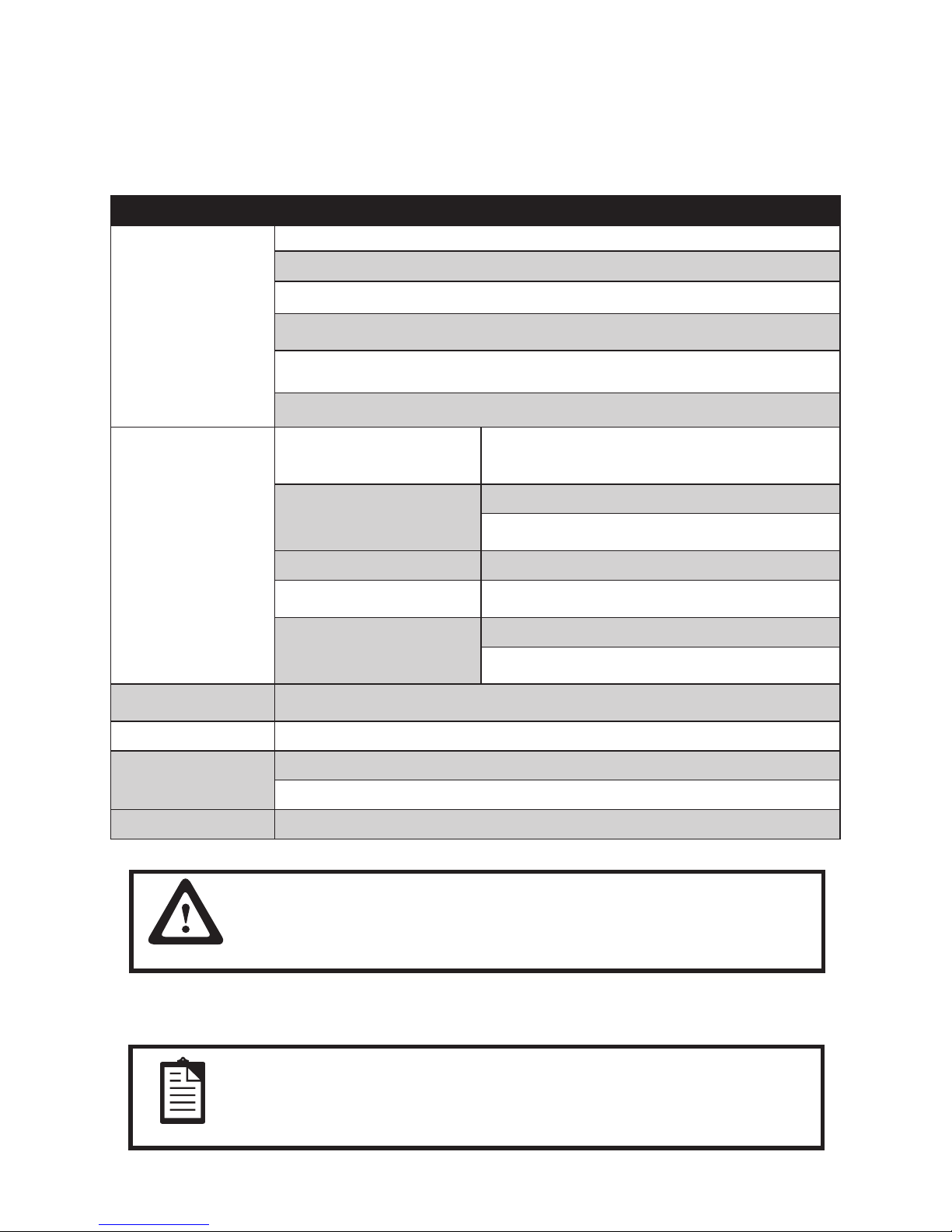
Product Description
Project Name Spec Description
LED Panel
7”
Resolution: 800x480
Brightness: 350nits
Contrast Ratio: 500:1(typ)
Response Time:25 ms (typ)
Lifetime: 20,000hours
USB transfer board
Controller (Display Link)
DL115 Single core
Max Resolution: 1024x600
Memory
SDAM on board
256Mb(16Mx16)
Input USB 2.0
Output TTL
PCB
4-layer
Color: green
Power input USB DC 5V
Power consumption 2.5W
Environment
Operation Temperature:0~40°C
No Operation Temperature:-20°C~60°C
OS Windows XP, Windows Vista, Windows7
CAUTION
Because of the special USB driver required, the USB display cannot
function as primary display during boot-up. An additional display must
be used to install the USB driver.
Add colloidal particle (PVC 45P, external mode BK-001) and irondust core (outside diameter14.2, inside
diameter 6.35, length 28.5) in cable
NOTE
The power cable near products-side clip the irondust core which
function is electromagnetic interference suppression and around two
times; User do not move or remove the irondust core please.
Page 6
6
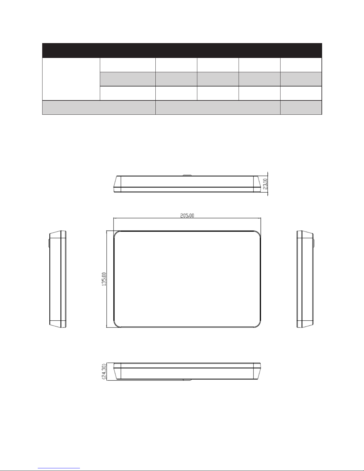
Mechanical Specication
Item Min� Typ� Max� Unit
USB Display Size
Horizontal (H) 204.5 205 205.5 mm
Vertical (V) 134.7 135 135.5 mm
Depth (D) 22.9 23.1 23.3 mm
Weight 850 g
Mechanical Dimension
Page 7

7
CHAPTER 3
INSTALLATION
Unpacking the USB Display
Open the carton and verify that the following items are present:
1 USB display with USB or JST cable.
4 M4x8mm screws
Minimum Computer Hardware Requirements
For 1-2 USB displays, business usage, productivity target. This may not provide full frame rate DVD
playback at full screen.
1.2GHz Single Core CPU
512MB memory
For 3 USB displays where 1 could run DVD video while also targeting productivity and business apps. Will
support only 1 video of DVD resolution at full screen:
1.6GHz CPU
1GB memory
For 6 screens where 1 screen can run full screen DVD video:
1.8GHz Core Duo
1GB memory
At least one USB 2.0 port.
30 megabytes(MB) of free disk space.
Primary display
USB display Connections
1. Connect the USB Type A one of your computer’s USB ports. Or connect the JST connector and JST cable
of the terminal.
2. The USB display is in an ON state: video should be displayed on your USB display once the DisplayLink™ driver is installed on your computer.
Page 8
8
Installing the DisplayLink Software Drivers
The DisplayLink technology enables video-over-USB. It allows your USB display to use one USB cable for
power, video.
NOTE
1. This USB Display can not function as Primary display during bootup. An additional display must be used to install the DisplayLink
driver.
2. If you have v3.x,R4.1orR4.2 DisplayLink software installed you
must uninstall it, using the Windows Add/Remove Programs feature
before installing this release. Devices will continue working after
this release is installed.
IMPORTANT
Do not connect the USB display to your PC before the install.
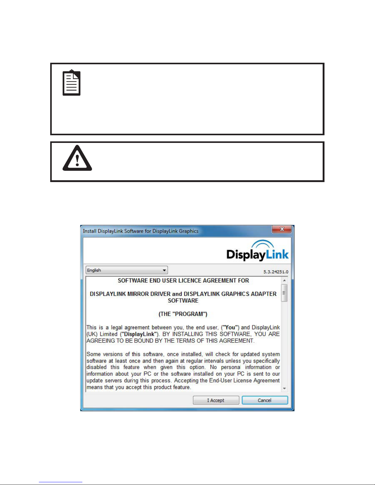
1. Run the Driver, Double click the driver for USB display.
2. Click Ye s .
3. The Display Link software end user license agreement window opens.
Page 9
9
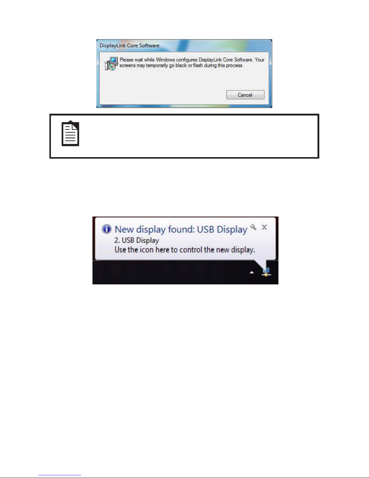
4. Click I Accept. The following screen appears during install
NOTE
The screen may ash or go black during the install. No message will be
shown at the end of the install.
5. No message will be shown at the end of the install. Reboot your computer after the install is complete.
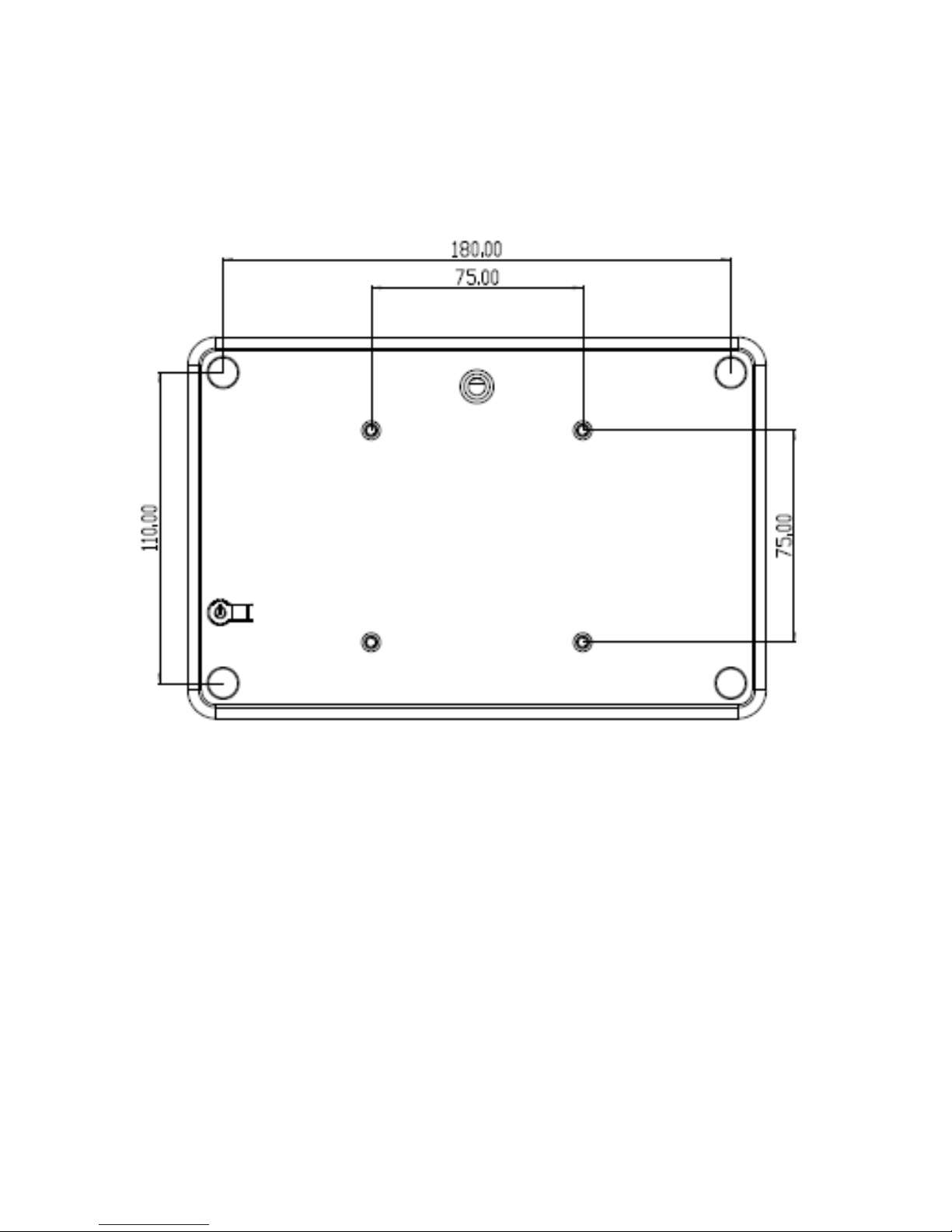
After the USB display is plugged in via USB cable, the USB display shape icon will appear in the system tray
and the following message will be displayed:
Page 10
10
CHAPTER 4
MOUNTING
Rear VESA Mount
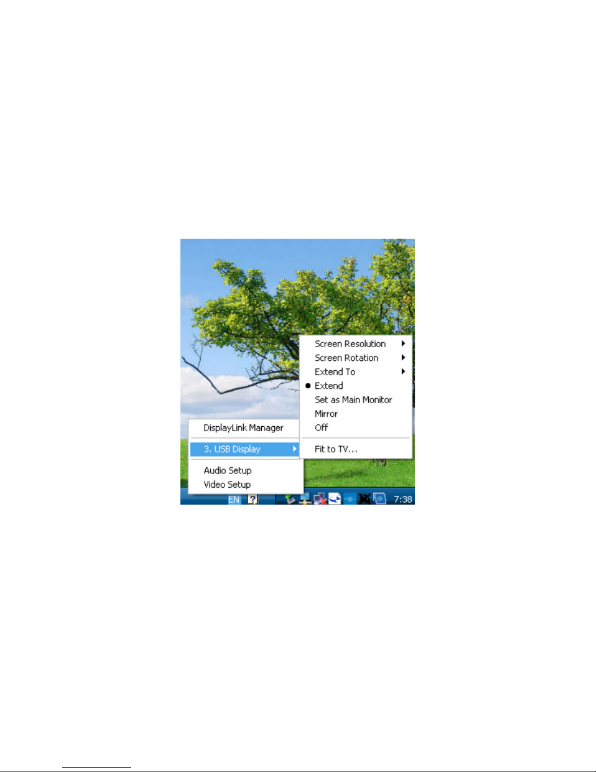
A four-hole 75x75mm mounting pattern for M4 screws is provided on the rear of the USB display
.
Page 11
11
CHAPTER 5
OPERATION
Power
To turn the USB display on or off, press the USB display power button on the back of the USB display once.
The system consumes low power when in SLEEP and OFF modes.
Video
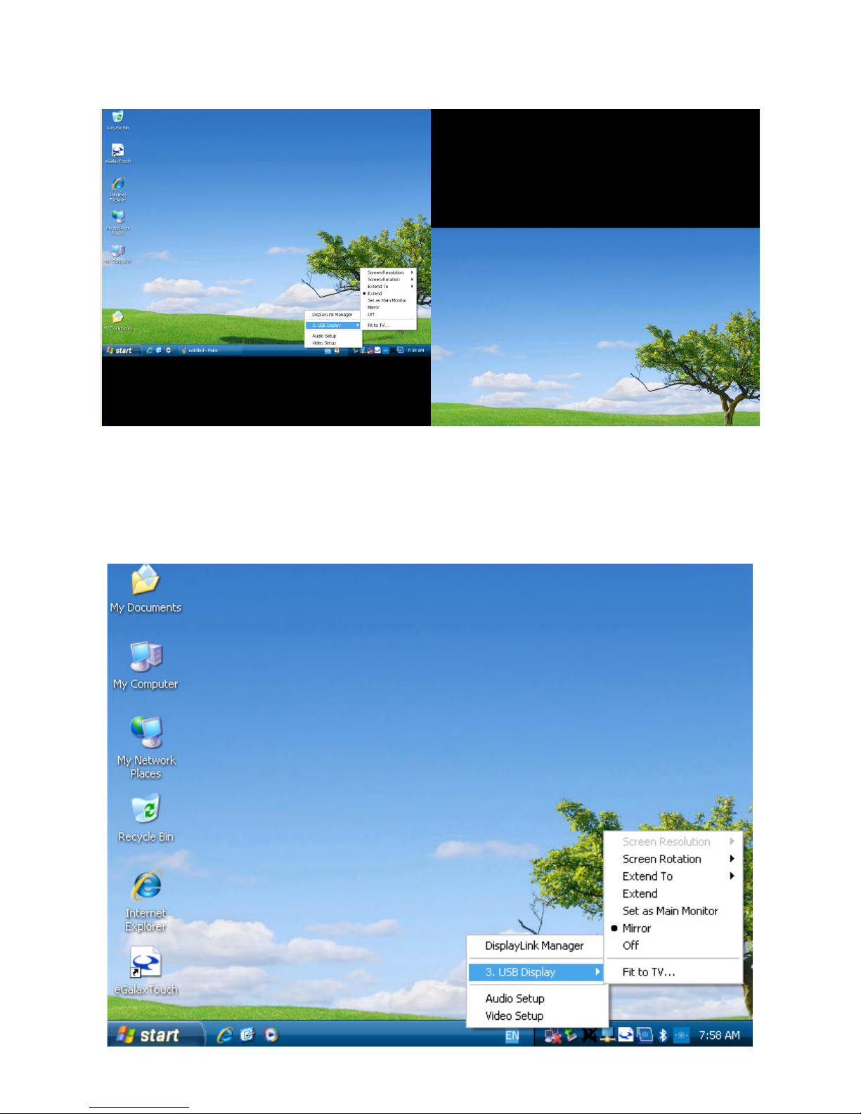
1. Display options can be selected by pressing the USB display shape icon in the system tray.
Page 12
12
2. In Extend Mode (default), the USB display acts as an extension of the primary display desktop. The resolutions of the USB display and the primary display are maintained.
3. In Mirror mode, the same video resolution, color depth and refresh rate are sent to both displays. The
video resolution that is sent depends on the primary display’s native resolution. For primary displays
with native resolution higher than 800x480 (most cases), the primary graphics device will automatically
select, from its supported resolutions, the highest resolution that ensures the whole desktop ts on the USB
display. For primary displays with native resolution lower than 800x480, the desktop will be letter-boxed
on the USB display to maintain the aspect ratio.
Page 13
13
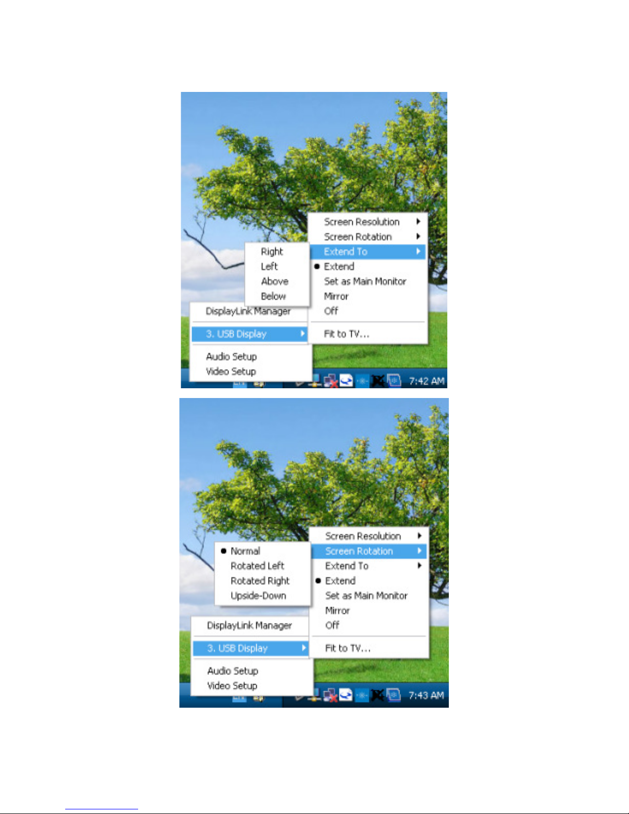
Setting the USB display mode:
1. Click the DisplayLink icon on the taskbar. The menu appears as shown below.
Page 14
14
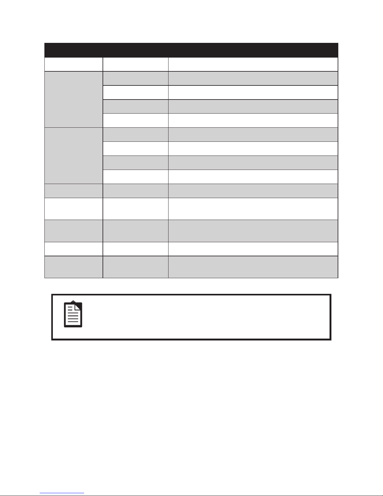
2. Select an option from the menu, using the following table for the options available.
Menu Option Sub-menu option Description
Screen Resolution Displays a list of available resolutions.
Screen Rotation
Normal No rotation is applied to the USB display
Rotated Left Rotates the extended or mirrored display by 270 degrees.
Rotated Right Rotates the extended or mirrored display by 90 degrees.
Upside-Down Rotates the extended or mirrored display by 180 degrees.
Extend to
Right Extends the display to the right of the main display.
Left Extends the display to the left of the main display.
Above Extends the display to the above of the main display.
Below Extends the display to the below of the main display.
Extend Extends your desktop onto the secondary display.
Set as Main
Monitor
Sets the secondary display as the main display.
Mirror
Copies what is on the main display and reproduces it on the
secondary display.
Off Switched off the secondary display.
Fit to TV
Opens a GUT to change the size of the Windows desktop so
it ts on a TV screen.
NOTE
In Windows XP OS, the USB display cannot be setting as main monitor
and setting as mirror mode
Page 15
15
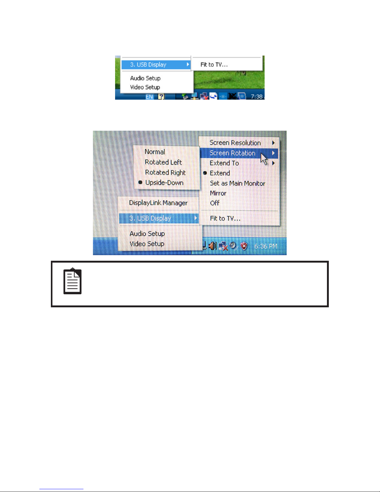
Monitor Rotation
1. Find the USB display icon on the tool bar, and press that right button of the mouse.
2. Select the “USB Display” rst, and then select the “Screen Rotation”.
3. Select the direction you want, ”Normal, Rotated Left, Rotated Right or Upside-Down”
NOTE
Partner Tech Utility can’t support “Rotated Left” and “Rotated Right”.
Page 16

16
CHAPTER 6
TECHNICAL SUPPORT
If you are experiencing trouble with your USB display, refer to the following suggestions.
If the problem persists, please contact your local dealer.
Solutions to Common Problems
Problem Suggested Troubleshooting
The USB display does not
respond when turning on the
system.
Check that the USB cable is correctly attached to the USB display and
the computer.
Disconnect and reconnect the USB cable.
USB display is blank.
The USB display or computer module may be in SLEEP mode. Press
any key / move the mouse the USB display to see if the image reappears.
If none of the above steps worked, restart the PC.
 Loading...