

Page 1
XXXXXXX
WARNING • PLEASE READ
For your own safety please read this manual before attempting to operate your new unit. Failure to follow instructions
can result in serious personal injury.Spend a few moments to familiarize yourself with your trimmer before each use.
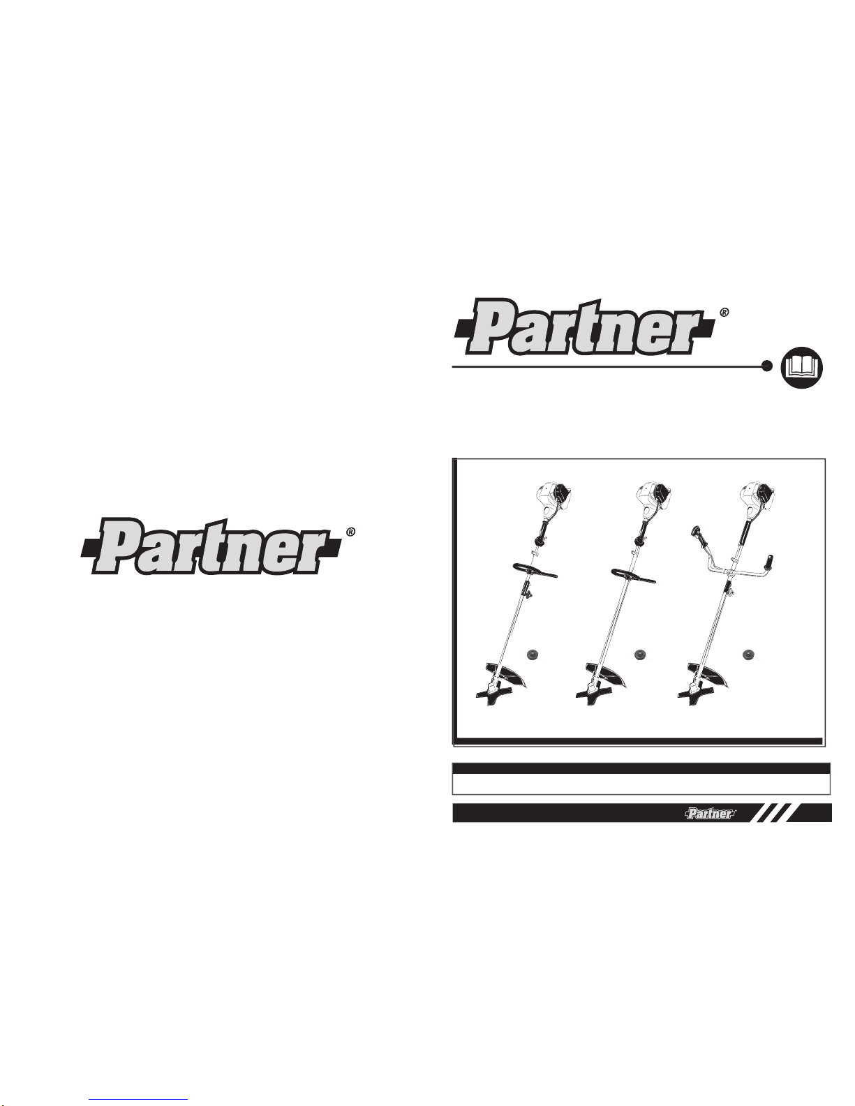
BC 435L
BC 435L
BC 435B
Husqvarna AB
SE-561 82 Huskvarna
Sweden
Model No.: BC 435L / BC 435B
GB
Page 2
2
WARNING! When using gas tools, basic safety precautions, including the following, should always be followed to
reduce the risk of serious personal injury and/or damage to the unit.
Read all these instructions before operating this product and save these instructions.
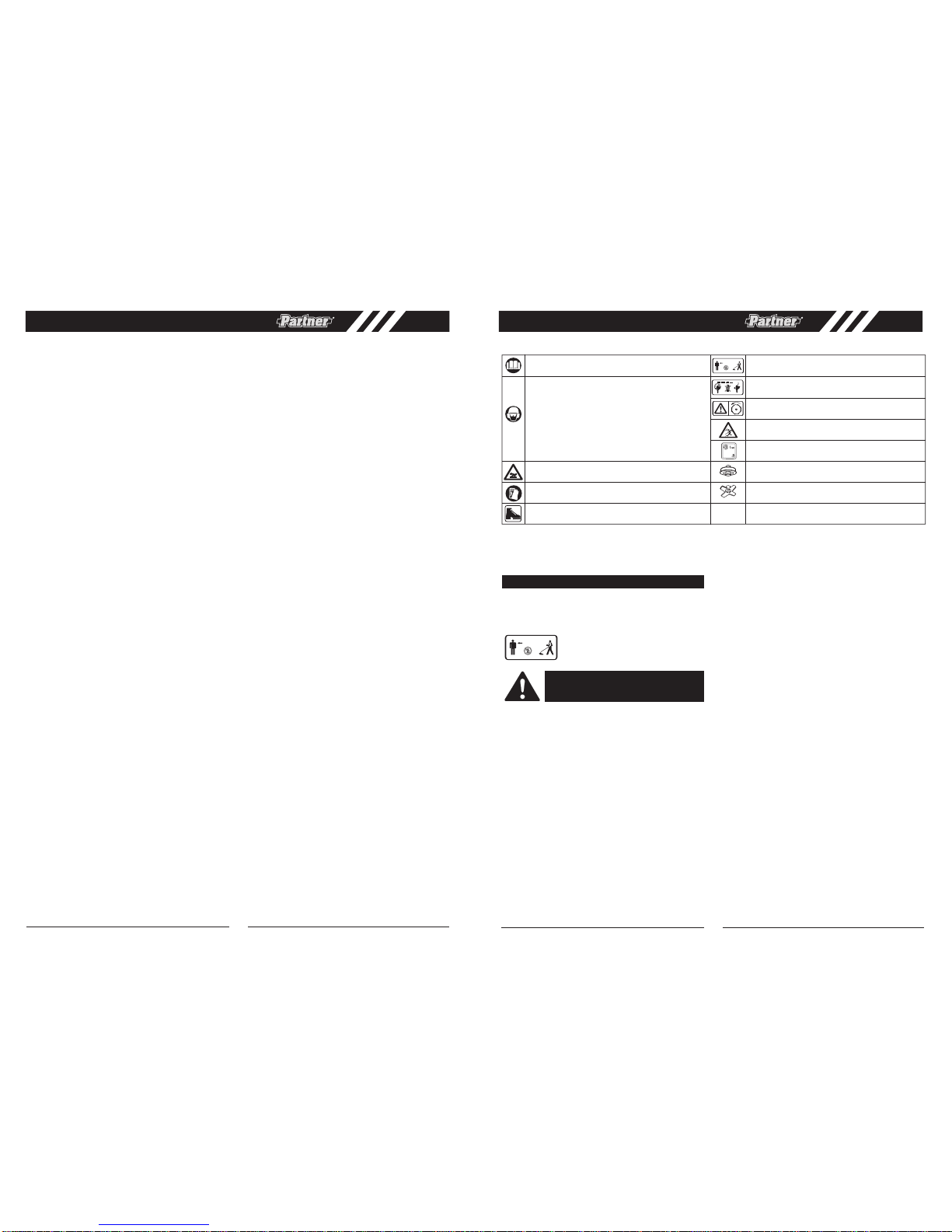
Meaning of symbols marked on the product
Read the user manual before using the machine
Whenever the machine is in use, safety goggles
must be worn to safeguard against flying object,
as must ear protectors, such as a soundproof helmet, in order to protect the operator’s hearing. If
the operator is working in an area where there is
a risk of falling objects, a safety helmet must also
be worn
15m(50ft)
Keep people or animals at least 15m away from
the machine during operation
Warning! Cutting elements continue to rotate
after the engine turned off
Warning! Hot surface
Wear gloves to protect your hands
Warning: Rotating blades
112
Beware of thrown objects
10000 min
-1
Acoustic power level LWA accordance with
directive 2000/14/EC + 2005/88/EC
Maximum rotational frequency of the spindle for
cutting head
Maximum rotational frequency of the spindle for
blade
Wear feet protection
READ YOUR USER MANUAL AND ALL SUPPLEMENTS (IF ANY ENCLOSED) THOROUGHLY BEFORE
OPERATING YOUR UNIT.
1. Wear close fitting, tough work clothing that will
provide protection, such as long slacks or trousers,
safety work shoes, heavy duty work gloves, hard hat,
a safety face shield, or safety glasses for eye protection and a good grade of ear plugs or other sound
barriers for hearing protection.
2. Prequel in a safe place.
Open fuel cap slowly to
release any pressure which may have formed in fuel
tank.To prevent a fire hazard, move at least 10 feet
(3 meters) from fueling area before starting.
3. Comply with all fire prevention regulations. com-
pliance with all local, state, or federal laws in the
united states is the user’s responsibility.Your unit
comes with a spark arrester screen furnished in the
user kit. Replacement spark arrester screen kits are
available from distributor.
4. Turn
unit off before setting it down.
5. Always hold unit firmly with both hands, the
thumb and fingers encircling the handles.
6. Keep all screws and fasteners tight.Never operate
your equipment when it is improperly adjusted or not
completely and securely assembled.
7. Keep handles dry, clean and free of fuel mixture.
8. Keep stringhead as close to ground as practical.
Avoid hitting small objects with stringhead.When cutting on a slope, stand below stringhead.NEVER cut
or trim on a hill or slope, etc. if there is the slightest
chance of slipping, sliding or losing firm footing.
9. Check area you will be trimming for debris that
may be struck or thrown during operation.
10. Keep all parts of your body and clothing away
from stringhead when starting or running engine.
Before starting engine, make sure stringhead will not
come in contact with any obstacle.
11. Stop engine before examining cutting line.
12. Store equipment away from possible ignition
s
ources, such as gas-powered wate
r heaters,
clothes dryers, or oil-fired furnaces, portable
heaters, etc.
13. Always keep the debris shield, stringhead, and
engine free of debris build-up.
14. Operation of equipment should always be restricted
to mature and properly instructed individuals.
15. WARNING: The emission of exhaust gases is toxic.
16. Emergency Stopping Procedure. When it is necessary to stop engine immediately, DEPRESS the
switch to stop.
17. This unit has a clutch, routines for checking that
the cutting attachment stops turning when the engine
idles.
WARNING: Keep children, bystanders, and
animals 50 feet (15 meters) away. If
approached stop unit immediately.
WHAT TO DO
15m(50ft)
GENERAL SAFETY RULES . . . . . . . . . . . . . . . . . . . . . . . . . . . . . . . . . . . . . . . . . . . . . . . . . . . . . . . . . . . . . . . . . . . .2
• What to do
• Brush / grass blade safety precautions
• What not to do
GENERAL IDENTIFICATION . . . . . . . . . . . . . . . . . . . . . . . . . . . . . . . . . . . . . . . . . . . . . . . . . . . . . . . . . . . . . . . . . . . .4
• Safety features
SPECIFICATIONS . . . . . . . . . . . . . . . . . . . . . . . . . . . . . . . . . . . . . . . . . . . . . . . . . . . . . . . . . . . . . . . . . . . . . . . . . . . .5
ASSEMBLY INSTRUCTIONS . . . . . . . . . . . . . . . . . . . . . . . . . . . . . . . . . . . . . . . . . . . . . . . . . . . . . . . . . . . . . . . . . . . .6
• “Loop With Barrier” handle installation
• “Bullhorn” handle installation
• Cutting attachment guard installation
• Cutting head installation
• Remove and installation the blade cover
• Blade installation
• Remove and installation the blade cover
FUEL AND ENGINE OIL . . . . . . . . . . . . . . . . . . . . . . . . . . . . . . . . . . . . . . . . . . . . . . . . . . . . . . . . . . . . . . . . . . . . . . .8
• Refueling
• Engine oil
OPERATING INSTRUCTIONS . . . . . . . . . . . . . . . . . . . . . . . . . . . . . . . . . . . . . . . . . . . . . . . . . . . . . . . . . . . . . . . . . . .10
• Shoulder harness
• Starting a cold engine
• Warm engine start
• Low temperature start
• To stop engine
TRIMMING INSTRUCTIONS . . . . . . . . . . . . . . . . . . . . . . . . . . . . . . . . . . . . . . . . . . . . . . . . . . . . . . . . . . . . . . . . . . . .11
• Additional safety precautions
• Cutting head line release
• Trimming procedures
• Cutting with blades
• Using weed blades
• Using a brush blade
MAINTENANCE INSTRUCTIONS . . . . . . . . . . . . . . . . . . . . . . . . . . . . . . . . . . . . . . . . . . . . . . . . . . . . . . . . . . . . . . . .13
• Replacing cutter line
• Air Filter
• Fuel Filter
• Carburetor Adjustment
• Spark Plug
• Cutting attachment guard knife shapening
• Storing a unit
• Removing a unit from storage
TROUBLE SHOOTING THE ENGINE . . . . . . . . . . . . . . . . . . . . . . . . . . . . . . . . . . . . . . . . . . . . . . . . . . . . . . . . . . . . .15
EU DECLARATION OF CONFORMITY . . . . . . . . . . . . . . . . . . . . . . . . . . . . . . . . . . . . . . . . . . . . . . . . . . . . . . . . . . . .16
1
GB
GB
11000 min
-1
Page 3
4
4
5
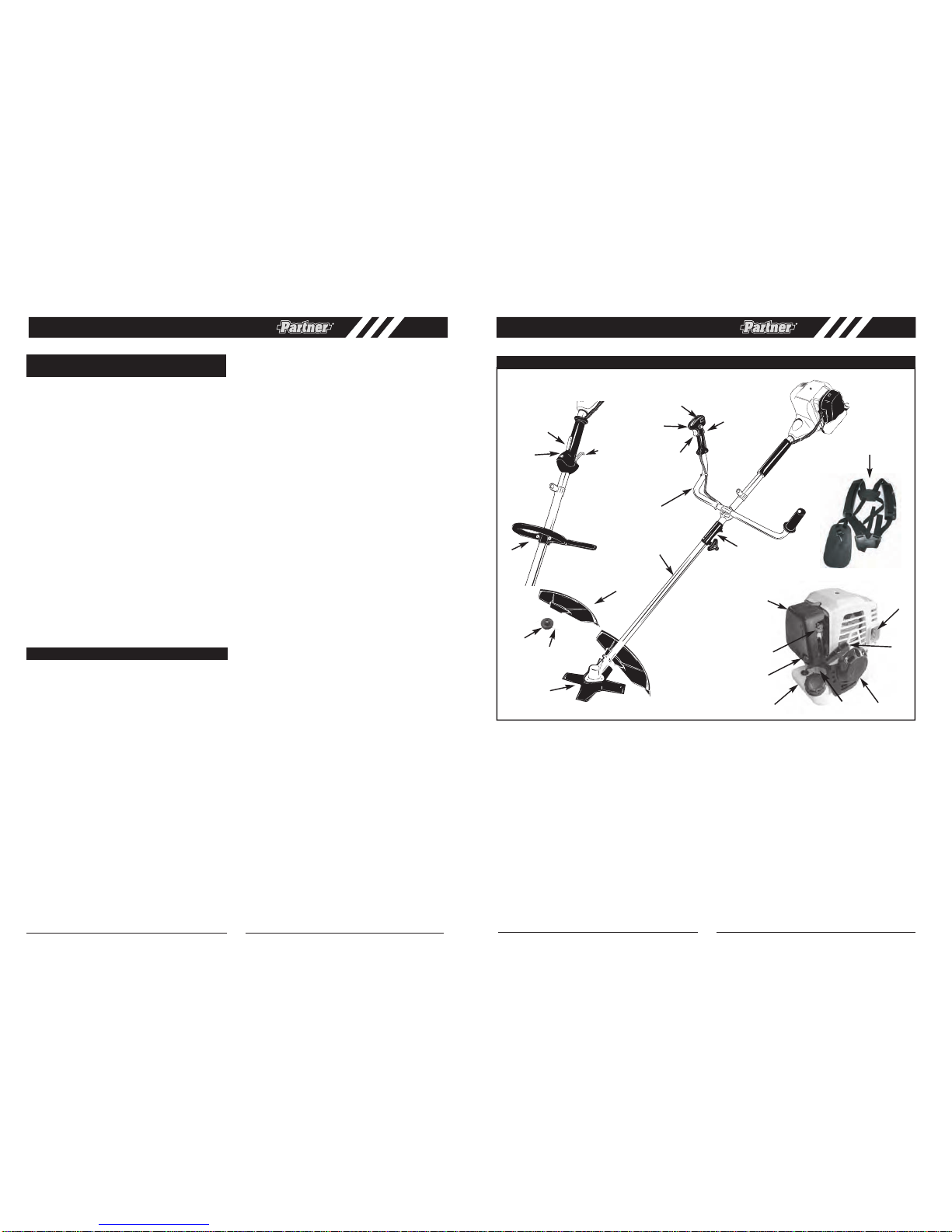
GENERAL IDENTIFICATION
8
9
7
13
21
14
17
18
12
16
15
SAFETY FEATURES
3 cutting attachment guard must be installed to prevent debris from being thrown at the operator and prevent the string
from extending longer than necessary.
17 MUFFLER SHIELD helps prevent hands, body and/or combustible materials from making contact with a hot muffler.
1. CUTTING HEAD
2. FLEXIBLE LINE
3. CUTTING ATTACHMENT
GUARD
4. BLADE
5. OUTPUT SHAFT
6. “LOOP WITH BARRIER”HANDLE
(BC 435L)
7. “BULLHORN” HANDLE
(BC 435B)
8. THROTTLE TRIGGER
9. ON/OFF SWITCH
10. THROTTLE TRIGGER LOCK
OUT
11. THROTTLE LOCK
12. CHOKE LEVER
13. STARTER ROPE HOUSING
14. FUEL TANK
15. AIR FILTER COVER
16. STARTER HANDLE
17. MUFFLER SHIELD
18. PRIMER BULB
19. HARNESS
20. COUPER
21. OIL TANK
(
BC 435B
/ BC 435L )
3
6
8
9
10
10
11
20
19
3
1. FOLLOW ALL WARNINGS and instructions regarding operation and blade installation.
2. BLADE CAN VIOLENTLY THRUST AWAY FROM
MATERIAL IT CANNOT CUT - Blade thrust can
cause amputation of arms or legs. Keep people
and animals 50 feet (15 meters) away in all directions.
If blade contacts foreign objects during operation,
turn off engine and allow coasting blade to stop.Then
check blade for damage. Always discard blade if it is
warped or cracked.
3. BLADE THROWS OBJECTS VIOLENTLY - You can
be blinded or injured. Wear eye, face, and leg protection. Always clear work area of any foreign objects
before using blade. Keep people and animals 50 feet
(15 meters) away in all directions.
4. INSPECT YOUR TRIMMER AND ATTACHMENTS
BEFORE EACH USE - Never use unless all bladeattaching hardware is properly installed.
5. BLADE COASTS AFTER THROTTLE IS RELEASED
- A coasting blade can cut you or bystanders. Before
per
forming any service on the blade, always turn off
engine, and be sure coasting blade has stopped.
6. 50 FEE T (15 meters) DIAMETER HAZARD ZONE Bystanders can be blinded or injured. Keep people
and animals 50 feet (15 meters) away in all directions.
1. DO NOT USE ANY OTHER FUEL than that recom-
mended in your manual.Always follow instructions in
the Fuel and Engine oil section of this manual.
Permanent damage to engine will result,
voiding manufacturer’s warranty.
2. DO NOT SMOKE while refueling or operating equip-
ment.
3. DO NOT OPERATE UNIT WITHOUT A MUFFLER
and properly installed muffler shield.
4. DO NOT TOUCH or let your hands or body come in
contact with a hot muffler or spark plug wire.
5. DO NOT OPERATE UNIT IN AWKWARD POSI-
TIONS, off balance, outstretched arms, or one-handed. Always use two hands when operating unit with
thumbs and fingers encircling the handles.
6. DO NOT RAISE CUTTING HEAD ab
ove ground level
while unit is operating. Injury to operator could result.
7. DO NOT USE UNIT FOR ANY PURPOSES OTHER
than trimming lawn or garden areas.
8. DO NOT OPERATE UNIT FOR PROLONGED PERI-
ODS. Rest periodically.
9. DO NOT OPERATE UNIT WHILE UNDER THE
INFLUENCE OF ALCOHOL OR DRUGS.
10. DO NOT OPERATE UNIT UNLESS CUTTING
ATTACHMENT GUARD AND/OR GUARD IS
INSTALLED AND IN GOOD CONDITION.
11. DO NOT ADD, REMOVE OR ALTER ANY COMPONENTS OF THIS PRODUCT. Doing so could cause
personal injury and/or damage the unit voiding the
manufacturer’s warranty.
12. DO NOT operate your unit near or around flammable
liquids or gases whether in or out of doors. An explosion and/or fire may result.
13. DO NOT USE ANY OTHER C
UTTING A
TTACHMENT.
Use only Partner replacement parts and accessories, which are designed specifically to enhance the
performance and maximize the safe operation of our
products. Failure to do so may cause poor performance and possible injury. Use only the cutting head
supplied with this product. Do not use any other cut-
ting attachment. Use of such attachments will void
your factory warranty and could result in serious bodily injury.
WHAT NOT TO DO
BRUSH / GRASS BLADE SAFETY PRECAUTIONS
2
1
BC 435L
BC 435B
GB GB
Page 4
6
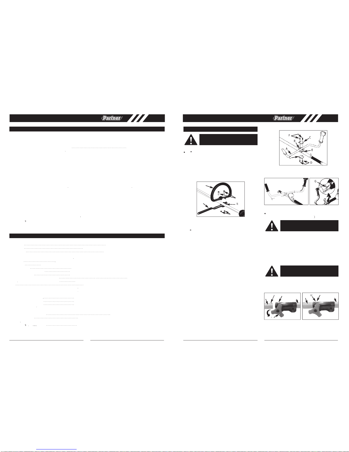
”HANDLE INSTALLATION
(BC 435L)
•
¨ HANDLE INSTALLATION
(BC 435B)
, ) A(e l dnah”nroh l l ub “ : t i kr esur uoymor fs t nenopmoc
fix
ing holder (B), clamp (C) and screws (D). (Fig. 1B)
2. Install the fixing holder (B) after the position point (E)
on the shaft, put the clamp (C) over the shaft and
tighten the 2 screws (D).
3. Install the bullhornhandle (A) on the fixing holder, put
the
other clamp(C) overbullhorn handle,adjut handle
to
appropriate position and tighten the other 2 screws
(
). (Fig. 1C)
4. Install wire tie (
G
) included in the user kit as shown
(Fig. 1D).
INSTALLINGTHE ATTACHMENT
(BC 435L
965874001
/BC 435B
NOTE:
To make installing or removing the attachment
easier, place the unit on the ground or on a work bench.
2A).
2. While firmly holding the attachment (B), push it
straight into the Quick-Change coupler (C) until the
release button (D) appears in the primaryhole (E) of
the Quick-Change coupler. (Fig. 2B)
3. Turnthe knob (A) clockwise to tighten. (Fig. 2C)
All attachments are designed to be used in the primary
hole unless otherwise indicated in the specific attach-
ments operators manual. If the incorrect hole is used, it
could result in injury, or damage to the unit.
ASSEMBLY INSTRUCTIONS
WARNING:
Please install the unit according
to the assemblyinstructions,orelseitmaybe
cause dangerous to the operator.
WARNING:
To avoid serious personal injury,
shut unit off before removing or installing
attachment.
CAUTION:
The release button must be in the
primary hole and the knob securely tightened
before operating this unit.
3 5 0
m
m
90ß
B
C
C
G
5
SPECIFICATIONS
Model No. . . . . . . . . . . . . . . . . . . . . . . . . . . .BC 435L . . . . . . . . . . . . . . . . . . . . . . . . . . . . . . . . . .BC 435B
(965874001)
Engine Type . . . . . . . . . . . . . . . . . . . . . . . . . . . . . .Air-cooled, 4-cycle, . . . . . . . . . . . . . . . . . . . . . . . . . . . . . . Air-cooled, 4-cycle,
. . . . . . . . . . . . . . . . . . . . . . . . . . . . . .Chrome Cylinder . . . . . . . . . . . . . . . . . . . . . . . . . . . . . . . . Chrome Cylinder
Displacement . . . . . . . . . . . . . . . . . . . . . . . . . . . . .35 cm
3
. . . . . . . . . . . . . . . . . . . . . . . . . . . . . . . . . . . . . . . . .
35 cm
3
Dry Weight . . . . . . . . . . . . . . . . . . . . . . . . . . . . . . .6
gK 5.6........................................ gK 53
Fuel Capacity . . . . . . . . . . . . . . . . . . . . . . . . . . . . .730 cm
3
. . . . . . . . . . . . . . . . . . . . . . . . . . . . . . . . . . . . . . . . 730 cm
3
Bump Head . . . . . . . . . . . . . . . . . . . . . . . . . . . . . .Twin Line Bump Feed . . . . . . . . . . . . . . . . . . . . . . . . . . . . . Twin Line Bump Feed
Blade 4 Teeth . . . . . . . . . . . . . . . . . . . . . . . . . . . . .4 Teeth . . . . . . . . . . . . . . . . . . . . . . . . . . . . . . . . . . . . . . . . 4 Teeth
Drive Shaft Length . . . . . . . . . . . . . . . . . . . . . . . . .66cm + 66cm . . . . . . . . . . . . . . . . . . . . . . . . . . . . . . . . . . . .66cm + 66cm
Cutting Width (Twin Line Head) . . . . . . . . . . . . . . .43cm . . . . . . . . . . . . . . . . . . . . . . . . . . . . . . . . . . . . . . . . . . .43cm
(Blade) . . . . . . . . . . . . . . . . . . . . . .23cm . . . . . . . . . . . . . . . . . . . . . . . . . . . . . . . . . . . . . . . . . . .23cm
Handle . . . . . . . . . . . . . . . . . . . . . . . . . . . . . . . . . .
“Loop With Barrier”
Handle . . . . . . . . . . . . . . . . . . . . . . .“Bullhorn” Handle
Drive . . . . . . . . . . . . . . . . . . . . . . . . . . . . . . . . . . . .Centrifugal Clutch . . . . . . . . . . . . . . . . . . . . . . . . . . . . . . . . .Centrifugal Clutch
Sound pressure level . . . . . . . . . . . . . . . . . . . . . . .101.6 dB(A) . . . . . . . . . . . . . . . . . . . . . . . . . . . . . . . . . . . . .101.6 dB(A)
Sound power level . . . . . . . . . . . . . . . . . . . . . . . . .111
17dB(A) . . . . . . . . . . . . . . . . . . . . . . . . . . . . . . . . . . . .111
17 dB(A)
Guarantee sound power level . . . . . . . . . . . . . . . . .112 dB(A) . . . . . . . . . . . . . . . . . . . . . . . . . . . . . . . . . . . . . . .112 dB(A)
Vibration level for racing (Max.) . . . . . . . . . . . . . .<15 m/s
. . . . . . . . . . . . . . . . . . . . . . . . . . . . . . . . . . . . . . . <15 m/s
Vibration level for idling (Max.) . . . . . . . . . . . . . .<15 m/s
. . . . . . . . . . . . . . . . . . . . . . . . . . . . . . . . . . . . . . . <15 m/s
Maximum Engine Performance . . . . . . . . . . . . . . .0.90 kW . . . . . . . . . . . . . . . . . . . . . . . . . . . . . . . . . . . . . . . .0.90 kW
Engine Speed (rotation
frequency) at recommended
max. spindle rotational frequency
(Bump Feed Head) . . . . . . . . . . . . .8700 min
-1
. . . . . . . . . . . . . . . . . . . . . . . . . . . . . . . . . . . . . 8700 min
-1
(Blade) . . . . . . . . . . . . . . . . . . . . . .9500 min
-1
. . . . . . . . . . . . . . . . . . . . . . . . . . . . . . . . . . . . . . 9500 min
-1
±200
min
-1
. . . . . . . . . . . . . . . . . . . . . . . . . . . . . . . . . . .3000
±200
min
-1
Fuel consump
ion . . . . . . . . . . . . . . . . . . . . . . . . . .700 g/kWh . . . . . . . . . . . . . . . . . . . . . . .. . . . . . . . . . . . . . .700 g/kWh
SPECIFICA TIONS
Model No. . . . . . . . . . . . . . . . . . . . . . . . . . . . . . . . . . . . . . . . . . . . . . . . .. .. .. . .. . . . . . . . . . . . . .BC 435L
Engine Type
r-cooled, 4-cycle,
. . . . . . . . . . . . . . . . . . . . . . . . . . . . . . . . .Chrome
Cylinder
Displacement
. . . . . . . . . . . . . . . . . . . . . . . .
. . . . . . . . . . . . . . . . . . . . . . . .
. . . . . . . . . . . . . . . . . . . . . . . .
. . . . . . . . . . . . . . . . . . . . . . . .
. . . . . . . . . . . .
. . . . . . . . . . . . . . . . . . . . . . . . . . .
. . . .
. . . . . . . . . . . . . . . . . . . . . . . . . . . . . . . . . . . . . . . . . . . . . . . . . . . . . . . . . .
. . . . . . . . . . . . . . . . . . .
. . . . . . .
. . . . . . . . . . . . . . . . . . . . . . . .
. . . . . . . . . . . . . . . . . . . . . . . .
. . . . . . . . . . . . . . . . . . . . . . . .
. . . . . . . . . . . . . . . . . . . . . . . .
. . . . . . . . . . . . .
. . . . . . . . . . . . .
. . . . . . . . . . . . . . . . . .35 cm
3
Dry Weight
. . . . . . . . . . . . . . . . . . . . . . . . . . . . . . . . . . . . . . . . .6.2Kg
Fuel Capacity
. . . . . . . . . . . . . . . . . . . . . . . . . . . . . . . . . . . . . . . . .730 cm
3
Bump Head
. . . . . . . . . . . . . . . . . . . . . . . . . . . . . Twin Line Bump Feed
Blade 4 Teeth
. . . . . . . . . . . . . . . . . . . . . . . . . . . . . . . . . . . . . . . . .4 Teeth
Drive Shaft Length
. . . . . . . . . . . . . . . . . . . . . . . . . . . . . . . . . . . . . . . . . 132cm
Cutting Width (Twin Line Head)
. . . . . . . . . . . . . . . . . . . . . . . . . . . . . . . . . . . . . . . . . . 43cm
(Blade)
. . . . . . . . . . . . . . . . . . . . . . . . . . . . . . . . . . . . . . . . . . .23cm
Handle
. . . . . . . . . . . . . . . . . . . . . . . .
“Loop With Barrier”
Handle
. . . .
. . . .
. . . . . . . . . . . . . . . . . . . . . . . . . . . . . . . . . . . . . . .Electronic
Drive
. . . . . . . . . . . . . . . . . . . . . . . . . . . . . . . . .Centrifugal Clutch
Sound pressure level
. . . . . . . . . . . . .. . . . . . . . . . . . . . . . . . . . . . . . 101.6 dB(A)
Sound power level
17 dB(A)
Guarantee sound power level
. . . . . . . . . . . . . . . 112 dB(A)
Vibration level for racing (Max.)
. . . . . . . . . . . . . . . . . . . . . . . . . . . . . . . . . . . . . . . . <15m/s
2
Vibration level for idling (Max.)
. . . . . . . . . . . . . . . . . . . . . . . . . . . . . . . . . . . . . . . . <15m/s
2
Maximum Engine Performance
. . . . . . . . . . . . . . . . . . . . . . . . . . . . . . . . . . . . . . . 0.90 kW
. . . . . . . . . . . . . . . . . . . . . . . . . . . . . . . . . . . . . . . 0.90 kW
Engine Speed (rotationa
frequency) at recommended
max. spindle rotational frequency
(Bump Feed Head)
. . . . . . . . . . . . . . . . . . . . . . . .
. . . . . . . . . . . . . . . . . . . . . . . .
. . . . . . . . . . . . . . . . . . . . . . . . . . . . . . . . .
. . . . . . . . . . . . . . . . . . . . . . .
. . . . . . . . . .
. . . . . . . . . . . . . . . . . . . . . . . . . .
. . . . . . . . . . . . .8700 min
. . . . . . . . . . . . .8700 min
-1
(Blade)
. . . . . . . . . . . . . . . . . . . . . . . . . . . . . . . . . . . . .9500 min
-1
. . . . . . . . . . . . . . . . . . . . . . . . . . . . . . . . . . . . . . .3000
±200
min
Fuel consump
ion
. . . . . .
. . . . . .
. . . . . . . . . . . . . . . . . . . . . . . . . . . . . . . . . . . . . 700 g/kWh
ing components from your user kit: handle (A & B),
screws (C) and nuts (D). (Fig. 1A)
2. Install the handle (B) after the position point (E) on
the shaft and tighten the 2 screws (C) and nuts (D).
C
GB GB
C
B
C
Page 5
8
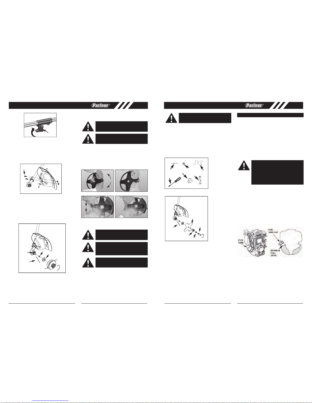
2. Install blade (C) with teeth pointing CLOCKWISE as
shown in the illustration (Fig. 6B).
3. Install flange (E) with FLAT SURFACE facing blade
(Fig. 6B).
NOTE: Make sure blade is centered on collar arbor.
4. Tighten nut (B) securely by turning it COUNTERCLOCKWISE with socket wrench (F) . Remove holding pin (Fig. 6B).
• Refueling
NOTE:
WARNING:Be sure the blade center hole is
properly sized to the collar arbor.
Fig. 6A
C
F
B
A
D
E
FUEL SYSTEM
GNINRA W :
Gasoline is highly flammable and explosive.
You can be burned or seriously injured when
handling fuel.
• Stop the engine and keep heat, sparks, and
flame away.
• Handle fuel only outdoors.
• Wipe up spills immediately.
7
• CUTTING ATTACHMENT GUARD
2. place the guard on the cutting shaft, then install
1. Install the cutoff knife as shown below.
clamp (A)on the guard. (Fig.3 )
3. Tighten screws (B).
NOIT A LLA T SNI DAEH GNITTUC •
. 1 Install spline sleeve (D) and gear collar (A) in turn
ensuring that collar spacer is in place (Fig. 4).
otno daeh gnittuc daerht dna )C( nip gnidloh t r esnI . 2
4) . giF( ylno dnah y b daeh gnittuc nethgiT . tfahs
• REMOVE AND INSTALLATIONTHE BLADE
COVER
1. Before assembling blades, please remove the blades
cover first.
2. Refer figure 5A and Figure 5B, hold the blades cover,
and pull sligtly the cover outward the cover can be
taken apart.
3. Refer to figure 5C and 5D, and assemble in the opposite way to cover the blades.
• BLADE INSTALLATION
1. To install the blade you will need the items illustrated
above (screwdriver not provided): holding pin (A),
retaining nut (B), blade (C), screwdriver (D), flange
(E), socket wrench (F) (Fig. 6A)
Fig. 2C
A
Fig. 3
B
A
B
A
D
C
Fig. 4
CAUTION: Before you take apartthe blades,
wear gloves to prevent any danger.
CAUTION:When the machine is not in use or
in transportation, make sure blades have
been covered.
Fig. 5A Fig. 5B
Fig. 5C Fig.5D
CAUTION: NEVER use unit if blade is
warped or has teeth that are chipped or missing. Replace a damaged blade immediately.
CAUTION: NEVER operate unit with a blade
unless metal blade guard is properly
installed. NEVER operate a unit withadamaged guard.
CAUTION: Always wear heavy-duty work
gloves when handling and installing a blade.
This engine is certified to operate on unleaded gasoline
with a pump octane rating of 93 or higher.
You may use regular unleaded gasoline containing no
more than 10% ethanol (E10) or 5% methanol by volume.
In addition, methanol must contain cosolvents and
corrosion inhibitors. Use of fuels with content of ethanol or
methanol greater than shown above may cause starting
and/or performance problems. It may also damage metal,
rubber, and plastic parts of the fuel system. Engine
damage or performance problems that result from using a
fuel with percentages of ethanol or methanol greater than
shown above are not covered by warranty.
Check the fuel level by looking through the translucent
fuel tank. If the fuel level is low, refuel in a well-ventilate d
area with the engine stopped. If the engine has been
running, allow it to cool first.
Never use stale or contaminated gasoline or an
oil/gasoline mixture.
Avoid getting dirt or water in the fuel tank.
To refuel, rest the trimmer on the ground with the fuel
tank cap facing up, as shown. Remove the fuel tank cap
and fill the tank with gasoline to the bottom of the filler
neck. Refuel carefully to avoid spilling fuel.
Do not overfill. There should be no fuel in the filler neck.
After refueling, tighten the fuel tank cap securely.
Never refuel the engine inside a building where gasoline
fumes may reach flames or sparks. Keep gasoline away
from appliance pilot lights, barbecues, electric appliances,
power tools, etc.
Spilled fuel is not only a fire hazard, it causes
environmental damage. Wipe up spills immediately.
Move at least 10 feet (3 meters) away from the fueling
source and site before starting the engine.
Fuel can damage paint and plastic. Be careful not to spill
fuel when filling your fuel tank. Damage caused by spilled
fuel is not covered under warranty.
Fig. 6B
Fig. 7A
GB GB
A
E
B
F
C
Page 6
9
The trimmer is shipped WITHOUT OIL in the engine.
NOTE:Fill oil before starting engine.
Running the engine with too little or too much oil can
cause engine damage.
Check the engine oil level before each use, or every 10
hours if operated continuously. Rest the trimmer on a level
surface, with the engine stopped and in an upright position.
NOTE:
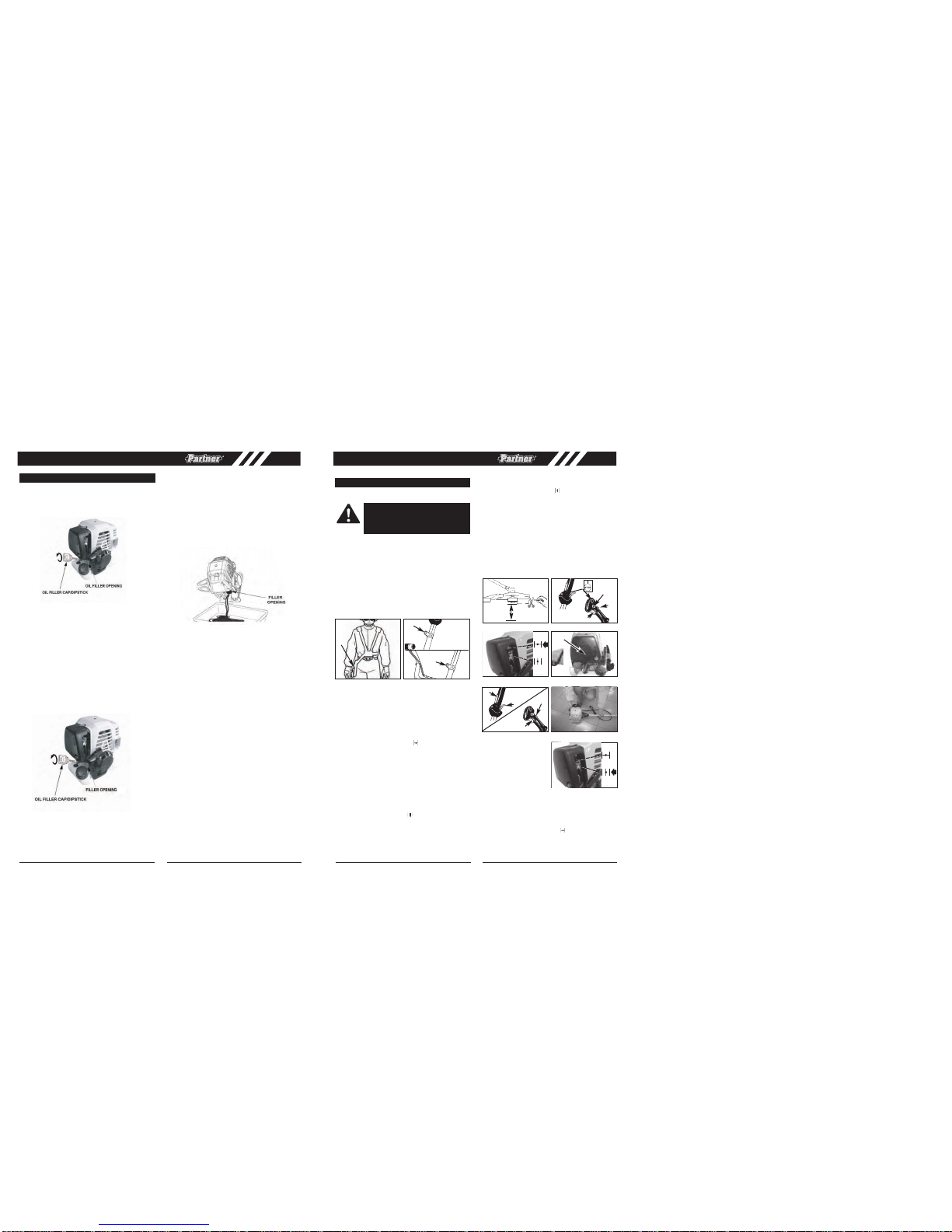
• Engine Oil Level Check
1. Place the trimmer on a level surface, and then
remove the oil filler cap/dipstick.
4. Screw in the oil filler cap/dipstick securely.
Running the engine with too little or too much oil can
cause engine damage.
NOTE:
4. Screw in the oil filler cap/dipstick securely.
2. Slowly add the recommended oil (included in the box)
to the bottom edge of the oil filler opening. Do not
overfill, as the engine oil tank capacity is small.
3. If the supplied oil is not used, add enough SAE 10W-
30 API service category SJ or later oil. Add oil until
the oil level is to the bottom edge of the oil filler
opening.
1. Remove the filler cap/dipstick and wipe it clean.
2. Insert and remove the dipstick without screwing it into
the filler opening. Check the oil level shown on the
dipstick.
3. If the oil level is low, fill to the edge of the oil filler hole
with the recommended oil . To avoid overfilling or
underfilling, be sure the engine is in a level position,
as shown.
ENGINE OIL
Drain the used oil while the engine is warm. Warm oil
drains quickly and completely.
• Engine Oil Change
• Engine Oil Recommendations
1. Place a suitable container below the engine to catch
the used oil, then remove the filler cap/dipstick and
drain the used oil through the filler opening. Allow the
used oil to drain completely.
Please dispose of used motor oil in a manner that is
compatible with the environment. We suggest you
take used oil in a sealed container to your local
recycling center or service station for reclamation. Do
not throw it in the trash, pour it on the ground, or pour
it down a drain.
2. With the engine in an upright position, fill to the edge
of the oil filler hole with the recommended oil.
3. Screw in the filler cap/dipstick securely.
Oil is a major factor affecting performance and service
life. Use 4-stroke automotive detergent oil.
SAE 10W-30 is recommended for all temperatures within
the recommended operating range for these trimmers.
The recommended operating range extends from 23° ~
104°F (-5° ~ 40°C).
The SAE oil viscosity and service classification are on the
API label on the oil container. Recommend that you use
API service category SJ or later.
NOTE: change the engine oil after first month or 10 hours.
NOTE: change the engine oil every 6 months or 50 hours.
10
Fig.7B
Fig.7D
Fig.7C
GB GB
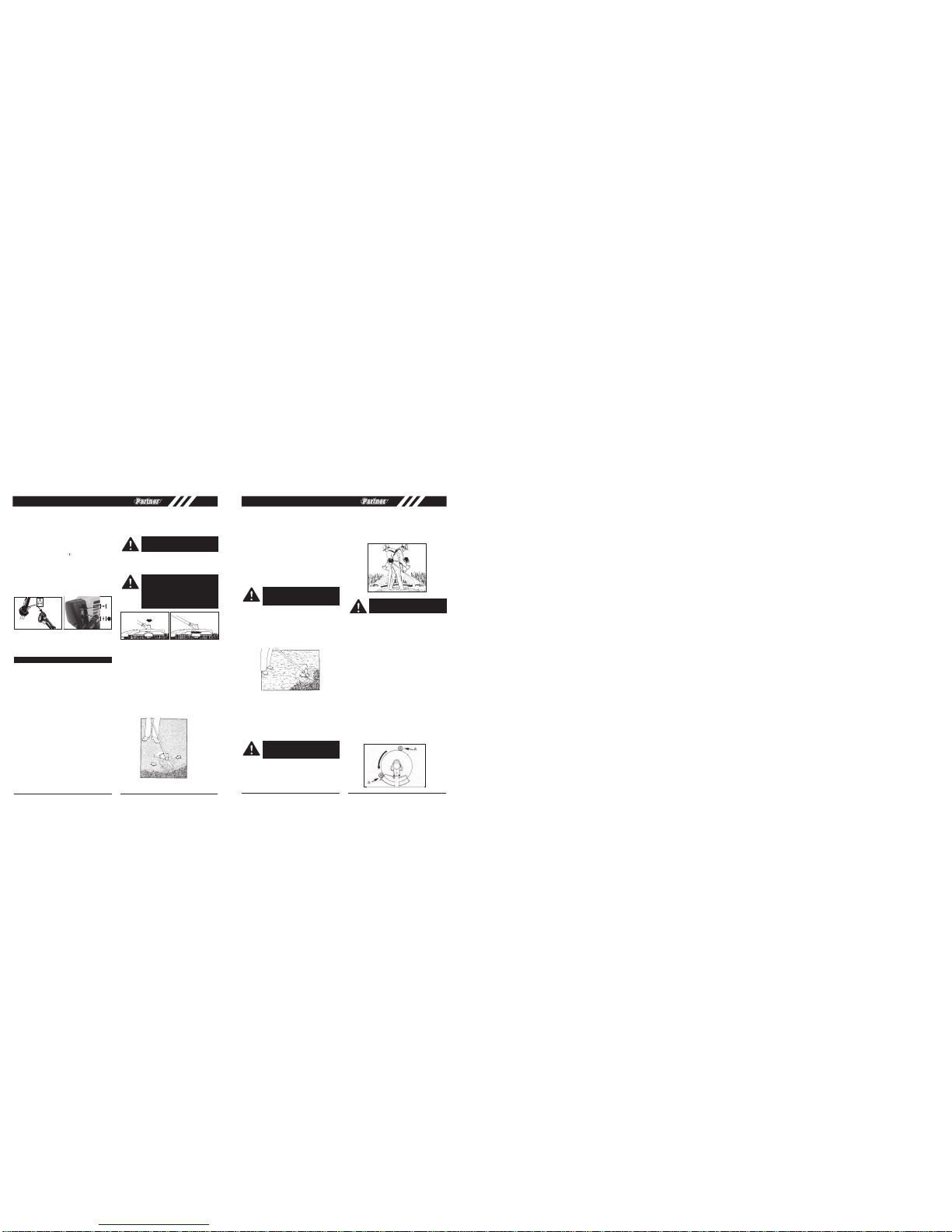
• SHOULDERHARNESS
NOTE: When you install the cutting attachment, please
follow thebelowrequirements:
1. Put the harness onso the shoulder strapis over your
shoulders.
2. Attache the harness clip (C) to the ring (D)mounted
on the shaft(Fig. 8A and 8B).
3. Adjust length of shoulder strap so stringhead is parallel to the ground as it hangs from the strap. A few
practice swings without starting engine should be
made to determinecorrectbalance.
NOTE: Detach theshoulderharness from the unit before
starting engine.
• STARTING A COLD ENGINE
NOTE: To minimize load on engine during starting and
warm-up, trim excesscutter line to 13cm (Fig.9A).
1. Press ON/OFF switch to the “RUN (I)” position (Fig.
9B).
2.3.Press the primer bulb 10 times.(Fig.9D)
Move choke lever to CHOKE“ ” position.(Fig.9C)
6.
If engine fails to start, repeat step 1 to 5.
If engine fails to start, refer to Starting a cold engine
section.
5.
Move choke lever to RUN “ ” position. Engine will be
started when pull starter rope 1 time. Continually warm
10 seconds after engine started, and then pull throttle
trigger to full position. (Fig. 9G)
1.
2.
NOTE:If engine failsto start afterrepeated attempts, refer
to Troubleshooting section.
NOTE: Alwayspull starter ropestraight out. Pullingstarter
at an anglewillcause rope to rub against theeyelet. This
friction will cause the ropeto fray and wear more quickly.
Always hold starter handle when rope retracts. Never
allow rope to snap back from extended position. This
could cause rope to snag or fray and also damage the
starter assembly.
OPERATINGINSTRUCTIONS
WARNING: ALWAYS WEAR SHOULDER
HARNESS when operatingunit withablade.
Attach harness to trimmer after starting unit
and engine isrunning at IDLE. Turn ENGINE
OFF beforedisconnectingshoulder harness.
Fig. 8A Fig. 8B
D
D
Fig. 9A Fig.9B
13cm
For String
Head
0-300mm
For blade
100-400mm
B
C
BC 435L
BC 435L
BC 435B
BC 435B
A
Fig. 9C Fig.9D
Fig. 9E
Fig. 9F
A
B
B
A
Fig. 9G Fig.9G
C
A
• WARM ENGINE START
Move choke lever to RUN ” “ position. Engine will be
started after pulling starter rope 2 times.(Fig.9G)
BC 435L
BC 435B
4. Set throttle lock (C): Press the throttle trigger lockout
(A) down and then while holding throttle trigger (B)
at partially open position, press down and hold
throttle lock (C). Release throttle trigger (B). Throttle
trigger (B)will now remain in the partially depressed
position;
If no throttle lock: Press the throttle trigger lockout
down and then while holding throttle trigger (B) at
one-third open position.(Fig. 9B)
Pull starter rope 3 times. (Fig. 9F)
3.
2. Press the primer bulb 10 times.(Fig.9D)
Move choke lever to CHOKE” ” position.
• Low temperature start (0 -5 C)
1. Press ON/OFF switch to the “RUN (I)” position (Fig.
10A).
O
Page 7
11
• TO STOPENGINE
Releasethrottle trigger.Let enginereturn toidle.Push and
hold ignitionstop switchuntil engine stops.
• ADDITIONAL SAFETY PRECAUTIONS
Before operating your unit, review ALL SAFETY PRECAUTIONSin this manual.
WARNING/ CAUTION
• IF UNFAMILIAR WITH TRIMMING OR CUTTING
techniques, practice the procedureswith ENGINE in
“OFF”position.
• ALWAYS
CLEAR WORKarea ofdebris such ascans,
bottles, rocks,etc. Striking objectscan cause serious
injury to operator or bystanders and also damage
equipment.If an objectis accidentally hit,immediately
TURN ENGINE OFFand examine equipment. Never
operate unitwith damagedor defectiveequipment.
• ALWAYS TRIMOR CUT ATHIGH ENGINE SPEEDS.
Do not run engine slowlyat start or during trimming
operations.
• DO NOT use equipment for purposes other than
trimming ormowing weeds.
• NEVER raisecutting head above knee height during
operation.
• DONOT operate unit withother people or animals in
the immediatevicinity. Allowa minimum of50 feet (15
meters
) betwee n operator and other people and
animals whentrimming ormowing.
• Allowadistance of 100 feet (30 meters) between
operator and other peopl e and animals when
SCALPING withcutting headcutter.
• IFOPERATING UNIT ONA SLOPE, stand belowthe
cutting attachment.DO NOT OPERATEon a slopeor
hilly inclineif thereis theslightest chanceof slippingor
losing yourfooting.
• CUTTING HEAD LINERELEASE
Torelease freshline, run engineat fullthrottle and“bump”
cutting headagainst lawn. Linewill automatically release.
The knife in thecutting attachmentguard willtrim excess
line(Fig. 11A).
• TRIMMING PROCEDURES
When properlyequipped with acutting attachment guard
and cuttinghead, your unit willtrim unsightly weedsand
tall grass in those hard-to-reach areas - along fences,
walls,foundations andaround trees.Itcan alsobe usedfor
scalpingto removevegetation downto theground foreasierpreparation ofagardenor tocleanoutapar ti
culararea.
NOTE:Even withcare, trimmingaround foundations,brick
or stone walls, curves, etc.,will result in above normal
string wear.
TRIMMING /MOWING
Swing trimmerwithasickle-like motionfrom side toside.
Donot tiltthe cuttinghead during theprocedure.Test area
to be trimmed for propercutting height.Keepcutting head
at samelevel foreven depthof cut(Fig. 12A).
Fig.10BFig.10A
A
TRIMMER INSTRUCTIONS
WARNING: DONOT use steelwire or plas-
tic-coatedsteel wireof anykind withyour cutting head.Serious operatorinjury can result.
CAUTION:Periodically removeweed wrapto
prevent overheating the drive shaft. Weed
wrap occurswhen strandsof weeds become
entangled aroundthe shaft beneaththe cutting attachmentguard (Fig.11B). Thiscondition prevents the shaft from beingproper ly
cooled.Remove weed wrapwith screwdriver
or similardevice.
Fig.11A Fig.11B
Fig.12A
12
CLOSERTRIMMING
Positiontrimmer straight aheadwith aslight tilt sobottom
of cutting headis above ground leveland string contact
occursat proper cuttingpoint.Always cutaway fromoperator.Do not pulltrimmer towardoperator.
FENCE/FOUNDATIONTRIMMING
Approach tr imming around chain link fences, picket
fences, rock walls and foundations slowly to cut close
without whipping string against the barrier.If the string
comes incontact with rock,brick walls, orfoundations, it
will breakor fray.If stringsnags fencing,it will snapoff.
TRIMMING AROUNDTREES
Trim aroundtree trunks withaslow approach so string
doesnot contactbark. Walkaround thetree trimmingfrom
left toright. Approach grass orweeds with the tipof the
string andtilt cuttinghead slightly forward.
SCALPING
Scalping refers toremoval of all vegetationdown to the
ground. To do this, tilt the cutting head to about a 30
degree angleto theright. Byadjusting the handleyou will
have bettercontrol during this operation.Do not attempt
this procedure ifthere is any chanceflying debris could
injure operator,other peopleor cause damageto property (Fig.12B).
DO NOTSWEEP WITHTRIMMER
Sweeping refers to tilting cutting head to sweep away
debris fromwalkways, etc.Yourtrimmer i
sapowerful tool
and smallstones or other suchdebris may behurled 50
feet (15 meters) or more, causing injury or damage to
nearby property such as automobiles, homes and windows.
• CUTTING WITH BLADES
Always weareye protectionand protective clothingwhen
cutting withablade.
Alwaysuse the harnessfor bladeoperations.
• USING WEED BLADES
SCYTHINGWEEDS
Scythingrefers tocutting bymoving theblade fromside to
side inalevelarc. It ismost effective withgrassy weeds
and lightundergrowth. Itshould not beused to cut
large,
tough weedsor woodygrowth (Fig.13).
• USING A BRUSHBLADE
SCYTHING
Scything maybe used with abrush blade forlight brush
andundergrowth. Itis notrecommended fortough growth.
BINDING
Topheavy growth suchas saplings andheavy brushcan
bind and stop the blade. Avoid binding by anticipating
which waythe growthwill lean,and cut fromthe opposite
side.
If the bladebinds in a cut stop theengine immediately.
Hold the unit up to preventthe blade from cracking or
breaking whilepushing the sapling awayfrom the cut to
free theblade.
AVOIDKICKOUT
Kickout isthe reaction ofamoving bladeif it contacts a
strong tree,brush orasolid object.The forcethat occurs
violently pushesthe blade away inan arc. Kickoutcould
cause lossof control resultingin injury tothe operator or
bystanders.
DO NOTUSEABLADE NEAR A CHAINLINK FENCE,
METAL STAKES, LANDSCAPE BORDERS OR BUILDING FOUN
DATIONS.
The Partner
blade guardis designed to reduce therisk of
kickout by providing stopsto brace the unit against the
object beingcut.
Place the saplingagainst the stop (A)so the rotation of
the bladecontinually drawsit intothe stop (A)(Fig. 14).
WARNING: Use extreme caution when
SCALPING. Keepadistanceof 50 feet (15
meters) betweenoperator, other peopleand
animals duringthese operations.
Fig.12B
WARNING:Beforeoperatingthis machinewith
ablade checkto ensureit isproperly installed.
Follow allwarnings listed in theblade safety
precautionssection inthis manual.
Fig.13
CAUTION: Do not use weedblades to cut
brush ortree saplings.
Fig.14
A
A
Pull starter rope 6 times.
5.
Move choke lever to RUN ” ” position.
Engine will be started when pull starter rope 2 times.
(Fig.10B)
Continually warm 10seconds after engine started, and
then engine will reach high speed.
6.
If engine fails to start, repeat step 1 to 5.
BC 435L
BC 435B
4. Set throttle lock (C):Press the lockout switch (A) down
and then while holding trigger (B) at partially open
position, press down and hold throttle lock (C).
Release throttle trigger (B).Throttle trigger (B) will now
remain in the partially depressed position If no
throttle lock: Press the throttle trigger lockout down
and then while holding throttle trigger (B) at
one-third open position.(Fig. 9B).
GB GB
BUMP
Page 8
13
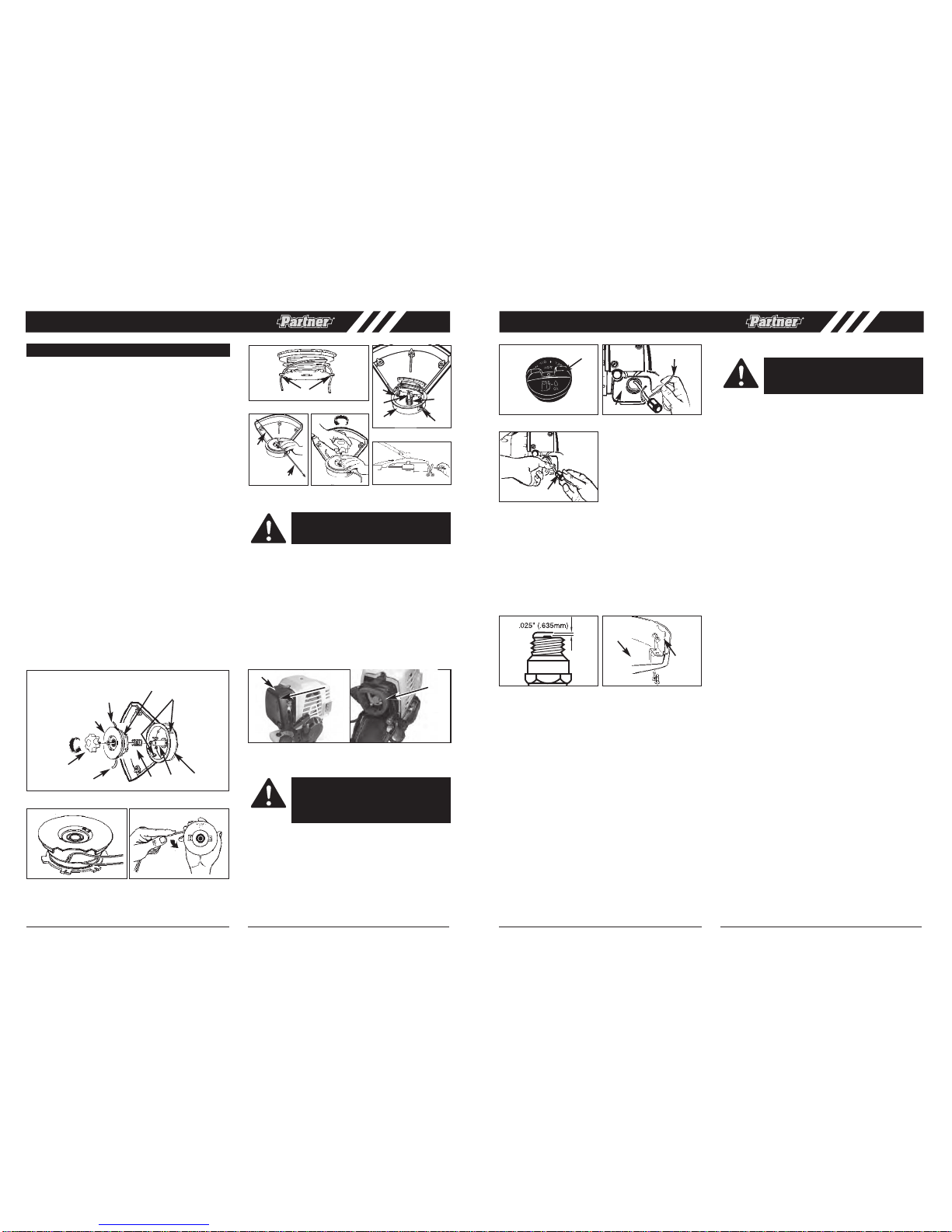
• REPLACING CUTTER LINE
1. Turn the nut (A) CLOCKWISE and remove it (Fig.
15A).
2. Remove the spool (C), and spring (D) from spindle
(E).
3. Remove any remaining cutter line.
4. Doublea32' (9.8m) length of .095 or .105" (.24 or
.27cm) cutter line. Place the looped center in one of
the slots (G) of the spool divider (Fig. 15B).
5. Wind as shown in illustration (Fig. 15C), keeping tension, with each half separated by the spool divider.
Wind to within 6" (15cm) of the ends.
6. Lock each end of line intoaslot (H) on opposite sides
of the spool (Fig. 15D).
7. Install the spring (D) over the spindle (E). Inserteach
end of the line through an eyelet (J) in the housing (F)
(Fig. 15E).
8. Lower the spool into the housing (E) while feedingthe
line through the eyelets (J). Ensure the spring seats
itself into the spool (Fig. 15E).
9. Once the spool is in place, apply pressure on the
spool compressing the spring. Pull each end of the
line (B) sharply
to unlock the line from the slots (Fig.
15F).
10. Continue to apply pressure to the spool until the knob
can be threaded COUNTERCLOCKWISE onto the
spingle.Tighten the knob securely by hand only (Fig.
15H)
11. Trim the excess line to approximately 5” (13cm). This
wil minimize load on engine durig starting and warmup.(Fig.15H)
• AIR FILTER
To Clean Air Filter:
1. Remove button (A) holding air filter cover in
place,
remove cover (B) and lift filter (C) from air box
(Fig.16).
2. Wash filter in soap and water. DO NOT USE GASO-
LINE!
3. Airdry filter.
4. Reinstallfilter.
NOTE: Replace filter if frayed, torn, damaged or unable to
be cleaned.
• FUEL CAP/FUEL FILTER
1. Completely remove fuel cap (A) from fuel tank (B)
to be able to remove fuel filter (D) from tank. Use a
piece of wire (C) withahook formed at the end to
pull filter out of tank. (Fig. 17A & Fig. 17B)
2. Pull filter (D) off withatwisting motion.
3. Replace
fuel filter (D). (Fig. 17C)
NOTE: Never operate the trimmer without the fuel
filter.Internal engine damage could result!
MAINTENANCE INSTRUCTIONS
A. KNOB
B. CUTTER LINE
C. SPOOL
D. SPRING
E. SPINDLE
F. HOUSING
G. DIVIDER SLOTS
H. SLOTS
J. EYELETS
A
B
C
B
G
D
E
F
J
Fig. 15A
Fig. 15B Fig. 15C
Fig. 15E
Fig. 15D
Fig. 15F Fig. 15G Fig. 15H
5” (13mm)
J
E
F
D
J
B
B
H
CAUTION: NEVER operate trimmer without
the air filter.The air filter must be kept clean.
If it becomes damaged, installanew filter.
Fig. 16
B
COUTION:
Remove fuel from unit and store
in approved container before starting this
procedure. Open fuel cap slowly to release
any pressure which may have formed in fuel
tank.
14
• CARBURETOR ADJUSTMENT
The carburetor was pre-set at the factory for optimum performance. If further adjustments are necessary, please
take your unit to the nearest Authorized Service Center.
• SPARK PLUG
1. Sparkplug gap = .025" (.635mm) (Fig. 18).
2. Torque to 105 to 130 inch pounds (12 to 15 N•m).
Connect spark plug boot.
• CUTTING ATTACHMENT GUARD KNIFE
SHARPENING
1. Remove cutter knife (A) from cutting attachment guard
(B) (Fig. 19).
2. Placeknifeinabench vise. Sharpen knife using a flat
file, being careful to maintain the angle of cutting
edge. File in one direction only.
• STORING A UNIT
1. Perform all the general maintenance recommended
in the Maintenance Section of your User Manual.
2. Clean exterior of engine, Output Shaft, cutting attachment guard and cutting head.
3. Drain fuel from the fuel tank.
4. After fuel is drained, startengine.
5. Run engine at idle until unit stops. This will purge the
carburetor of fuel.
6. Allo
w engine to cool (approx. 5 minutes).
7. Using a sparkplug wrench, remove the spark plug.
8. Pour 1 teasp
oon of clean 4-cycle oil into the
combustion chamber. Pull starter rope slowly several
times to coat internal components. Replace spark
plug.
9. Store unit inacool, dry place away from any source
of ignition such as an oil burner, water heater, etc.
• REMOVING A UNIT FROM STORAGE
1. Remove spark plug.
2. Pull starter rope briskly to clear excess oil from combustion chamber.
3. Clean and gap spark plug or install a new spark plug
with proper gap.
4. Prepare unit for operation.
5. Fill fuel tank with proper fuel.
Fig. 17A Fig. 17B
A
C
B
Fig. 17C
D
Fig. 18 Fig. 19
F
E
WARNING:Failureto follow these steps
may cause varnish to form in the carburetor
and difficult starting or permanent damage
following storage.
A
C
NOTE: clean the air filter element every 3 months or 25 hours.
GB GB
Page 9

15
TROUBLE SHOOTINGTHE ENGINE
PROBLEM PROBABLECAUSE CORRECTIVEACTION
Unit won’tstart or startsbut will
not run.
Incorrect startingprocedures. Follow instructionsin theUser Manual.
Incorrect carburetormixture
adjustment setting.
Have carburetoradjusted byan
Authorized ServiceCenter.
Fouled sparkplug Clean / gapor replaceplug.
Fuel filterplugged. Replace fuelfilter.
Unit starts,but enginehas low
power.
Incorrect leverposition onchoke. Move toRUN position.
Dirty sparkarrester screen. Replace sparkarrester screen.
Dirty airfilter. Remove, cleanand reinstallfilter.
Incorrect carburetormixture
adjustment setting.
Have carburetoradjusted byan
Authorized ServiceCenter.
Engine hesitates.
Incorrect carburetormixture
adjustment setting.
Havecarburetor adjusted byan
Authorized ServiceCenter.
No powerunder load.
Runs erratically.
Incorrectly gappedspark plug. Clean /gap or replaceplug.
Smokes excessively.
Incorrect carburetormixture
adjustment setting.
Have carburetoradjusted byan
Authorized ServiceCenter.
EU Declaration of Conformity
according to the regulations 98/37/EC, 2004/108/EC,
2000/14/EC+2005/88/EC, 2002/88/EC
For the followingequipment / product : Brush Cutter/Grass Trimmer, Gasoline
TypeDesignation
Trademark
:
BC 435L / BC 435B
Partner:
:
We herewith confirm to comply with the requirements set out in theCouncil
Directive 98/37/EC, 2004/108/EC, 2000/14/EC+2005/88/EC, 2002/88/EC.
For the evaluation ofthecompliancewiththeseDirectives,the following
standards were
applied:
EN ISO 11806 : 1997, EN ISO 11806:1997/AC, EN ISO 14982:1998
Sound pressure level :101.6dB(A)
Sound power level :111.17 dB(A)
Guarantee sound power level:112 dB(A)
Person responsible formakingthisdeclaration
Name, surname :
Position/Title :
Shanghai, P
. R.C.
2008/12/08
16
Importer's Name Husqvarna AB
Importer's Address :SE-561 82 Huskvarna, Sweden
Ronnie Goldman
Director of Engineering
Handheld Consumer Products
GB
 Loading...