

Partner 621504x117NA Instruction Book

GB
Instruction Book - Snowthrower Model 621504x117NA
FR
Livret d’instructions - Chasse-neige 621504x117NA
D
Betriebsanleitung - Schneeschleuder Modell 621504x117NA
I
Manuale di istruzioni - Spalaneve meccanico modello 621504x117NA
NL
Instructieboek - Sneeuwblazer Model 621504x117NA
DK
Instruktionsbog - Sneslynge model 621504x117NA
N
Instruksjonsbok - Snøfreser modell 621504x117NA
S
Instruktionsbok - Snöslunga, modell 621504x117NA
SF
Ohjekirja - Lumilinko malli 621504x117NA
ES
Manual de instrucciones - Quitanieves Modelo 621504x117NA
EE
Kasutusjuhend — Lumekoristaja mudel 621504x117NA
GR
ВйвлЯп Пдзгйюн – ЕкчйпнйуфЮсбт МпнфЭлп 621504x117NA
H
Használati kézikönyv – Hómaró 621504x117NA modell
LV
Lietošanas instrukciju — Sniega pūtējs Modelis 621504x117NA
LT
Instrukcija — Sniego valymo įrengimas Modelis 621504x117NA
PL
Instrukcja – Odœnie¿arka Model 621504x117NA
CZ
Uživatelská pøíruèka – Snìžná fréza – model 621504x117NA
SK
Návod na používanie – Snehová fréza, model 621504x117NA
RU
Руководство — Снегоочиститель, модель 621504x117NA
1740281 TP 199-4408-00-SW-R
1
5
2
3
12
2
4
1
2
1
14
15
9
3
1
1
2
3
1
2
8
12
10
11
4
2
1
1740281
1
2
5
5
2
3
1
2
6
3
2
6
7
8
16
17
4
1
7
5
14
14
14
14
9
2
1
4
2
12
13
17
15
10
3
1/8” (3mm)
4
5
11
3
4
5
6
1
12
2
3
4
5
1
1740281
3
2
13
2
5
14
1
3/32”
4
3
6
4
1
15
1
3
2
1
1740281
16 17
4
CONTENTS
HAZARD SYMBOLS AND THE MEANINGS 6..........
OPERATING SYMBOLS AND THEIR MEANINGS 6.....
RULES FOR SAFE OPERATION 7....................
ASSEMBLY 9.......................................
OPERATION 10.....................................
MAINTENANCE 12..................................
MAINTENANCE CHART 12...........................
TROUBLE SHOOTING CHART 14.....................
LIMITED WARRANTY 15.............................
General Information
This instruction book is written for a person with some mechanical ability.
Like most service books, not all the steps are described. Steps on how to
loosen or tighten fasteners are steps anyone can follow with some
mechanical ability. Read and follow these instructions before you use the
unit.
Know your product: If you understand the unit and how the unit
operates, you will get the best performance. As you read this manual,
compare the illustrations to the unit. Learn the location and the function of
the controls. To help prevent an accident, follow the operating instructions
and the safety rules. Keep this manual for future reference.
IMPORTANT: Many units are not assembled and are sold in cartons. It is
the responsibility of the owner to make sure the assembly instructions in
this manual are exactly followed. Other units are purchased in an
assembled condition. On assembled units, it is the responsibility of the
owner to make sure the unit is correctly assembled. The owner must
carefully check the unit according to the instructions in this manual before
it is first used.
GB
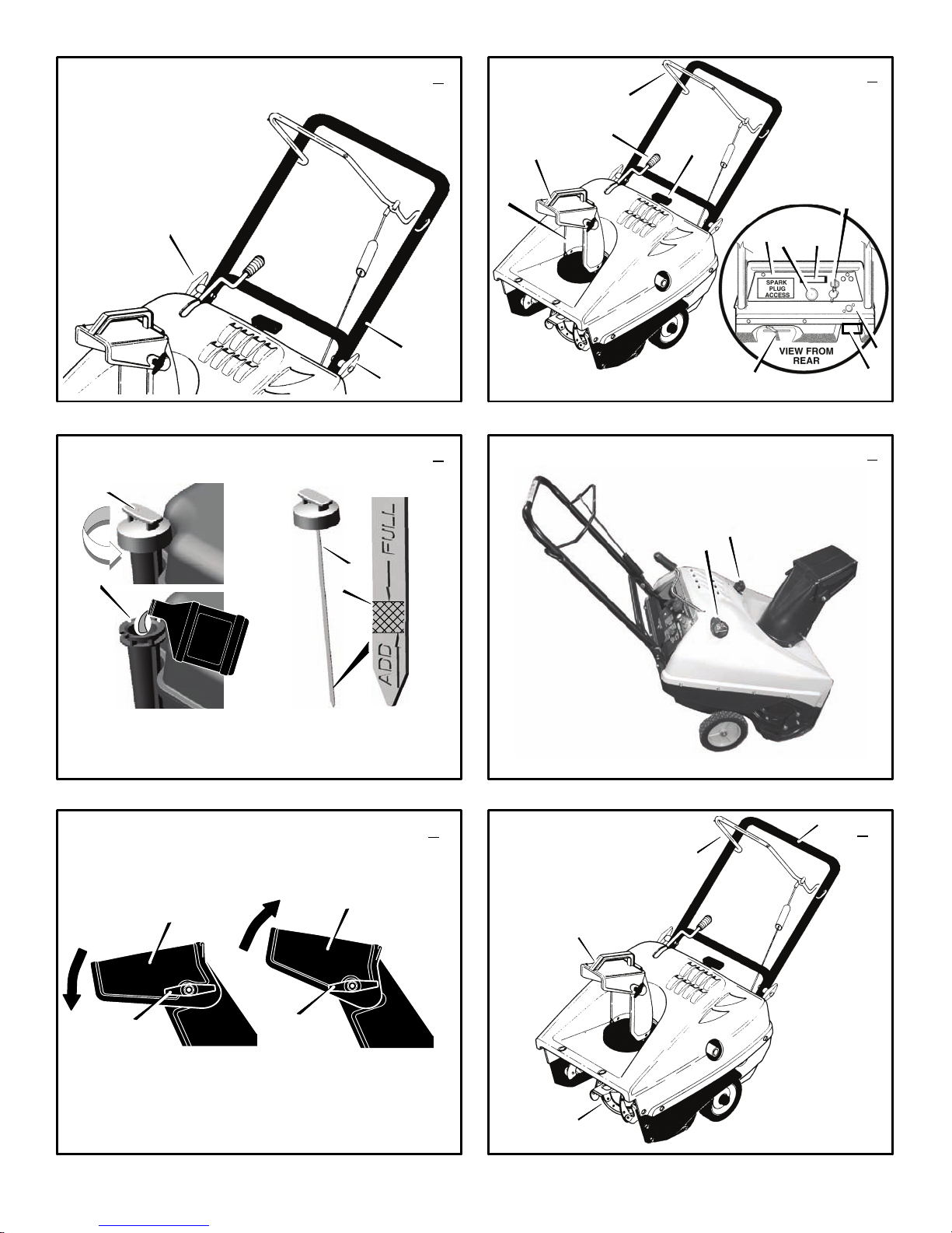
Controls & Equipment Features (see Figure 2)
Crank Assembly (2) -- Changes the direction of the discharge chute.
Chute Deflector (3) -- Changes the distance the snow is thrown.
Discharge Chute (4) -- Changes the direction the snow is thrown.
Auger Drive Lever (5) -- Starts and stops the auger (snow gathering and
throwing) which also propels the snowthrower.
Engine Features
Stop Switch (8) -- If equipped, move to the ON position to start the
engine.
Ignition Key (8) -- If equipped, insert and turn to the on position to start
the engine.
Primer Button (9) -- Injects fuel directly into the carburetor for fast starts
in cold weather.
Electric Start Button (10) -- On electric start models, used to start the
engine.
Switch Box (11) -- On electric start models, used to attach a 220 volt
electric power cord.
Recoil Starter Handle (12) -- Use to manually start the engine.
Choke Control (14) -- Use to start a cold engine.
Spark Plug Access Panel (15) -- Remove to access the spark plug.
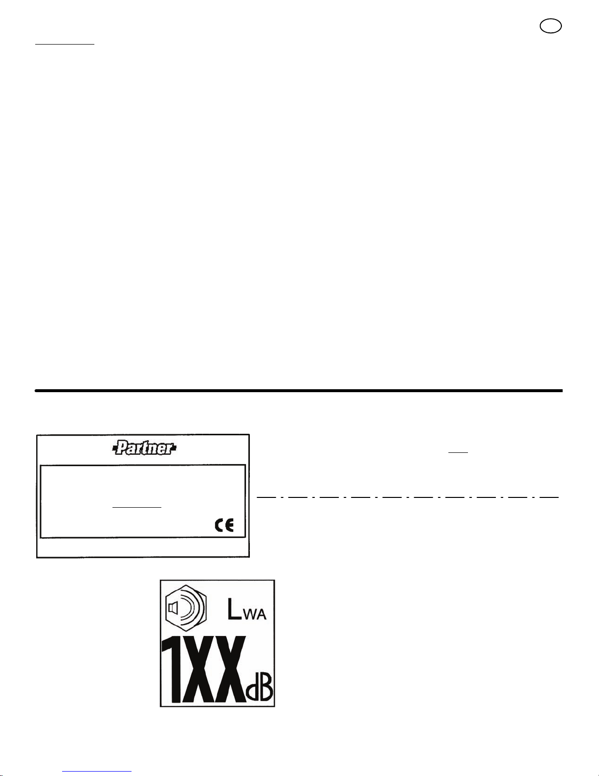
MODEL NO.: 621504x117NA
SKU No.:
YYYY MM DD:
SERIAL NO.:
4000 min-1
Assembled in Suzhou, China 215218
by Limac for The Partner Corporation
34 kg
Declared vibration emission values in accordance with Directive 98/37/EC.
Vibration Emission according to EN 1033;1996: 12,7
Values determined at the handle when the machine was operated stationary on a
concrete surface at 4000 min--1.
Declared airborne noise emissions of Lw
2000/14/EC, Annex V.
Sound Pressure Level at operator position 83 dB.
Values determined at ear according to the specifications of EN ISO 11201.
Declared airborne sound
power level of 104 dB(A) is in
accordance with Directive
2000/14/EC.
A 104 dB is in accordance with Directive
m/s2.
1740281
5
This manual contains safety information to make you
aware of the hazards and risks associated with snow
throwers, and how to avoid them. The snow thrower is designed and
intended for removal of snow, and should not be used for any other
purpose. It is important that you read and understand these
instructions, and anyone operating the equipment read and understand
these instructions.
GB
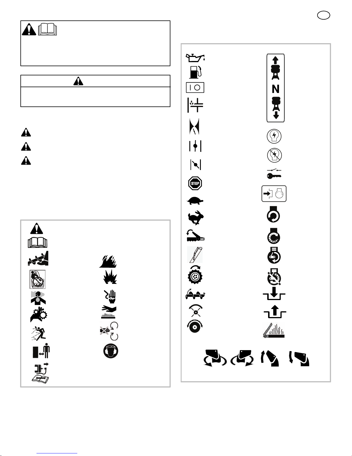
Operating Symbols and their meanings
These symbols are used on your equipment and defined in your operating
manual. It is important that you review and understand the meanings.
Failure to understand the symbols might result in harm to you.
Oil
WARNING
The engine exhaust from this product contains chemicals known to the
State of California to cause cancer, birth defects, or other reproductive
harm.
A signal word (DANGER, WARNING, or CAUTION) is used with the alert
symbol to indicate the likelihood and the potential severity of injury. In
addition, a hazard symbol may be used to represent the type of hazard.
DANGER indicates a hazard which, if not avoided, will result in
death or serious injury.
WARNING indicates a hazard which, if not avoided, could result
in death or serious injury.
CAUTION indicates a hazard which, if not avoided, might result
in minor or moderate injury.
CAUTION, when used without the alert symbol, indicates a
situation that could result in damage to the equipment.
Hazard Symbols and the meanings
These symbols are used on your equipment and defined in your operating
manual. Review and understand the meanings. The use of one of these
symbols combined with a signal word will alert you to potential hazards
and how to avoid them.
Safety Alert -- Identifies safety information about
hazards that can result in personal injury.
Operator’s Manual -- Read and understand before
performing any activity or running equipment.
Fuel
On Off
Primer bulb
Throttle
Choke off
Choke on
Stop
Slow
Fast
Engage
Foward
Neutral
Reverse
Ignition On
Ignition Off
Ignition Key
Push to engage
electric start
Electric
Start
Engine
Start
Rotating auger
Rotating impeller
Toxic fumes
Rotating gears
Thrown objects
Keep a safe distance
from the equipment.
Shut off engine and remove spark plug connector
before performing maintenance or repair work.
Fire
Explosion
Shock
Hot Surface
Never reach into
rotating parts.
Recommended ear
protection for extended
use.
Engage
Traction
Auger Collector
Auger Clutch
Drive Clutch
Discharge Chute
LEFT UP
RIGHT
Chute Deflector
Engine Run
Engine Off
Engage
Disengage
Heated Grips
DOWN
1740281
6
 Loading...