

Page 1

INSTRUCTION MANUAL
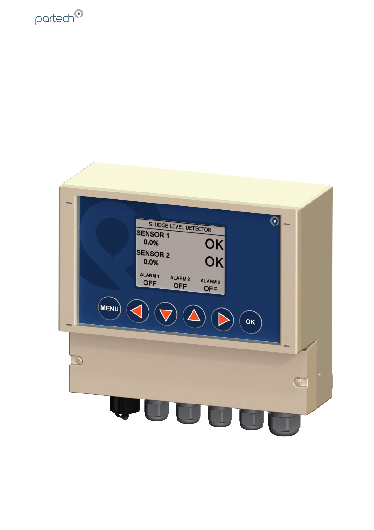
SludgeWatch 8200w²
Fixed Sludge Level Detector
Issue 01
Page 2

8200w² Monitor Instruction Manual
** This page is intentionally left blank **
Page 2 of 34 229844IM Issue 01 Issue Date 24/06/2019
Page 3

8200w² Monitor Instruction Manual
Table of Contents
1 Foreword.......................................................................................................................................................................... 5
2 Introduction...................................................................................................................................................................... 6
2.1 Manual Conventions................................................................................................................................................ 6
2.2 WaterWatch² Trademark......................................................................................................................................... 6
2.3 Scope of Manual...................................................................................................................................................... 6
2.4 Options.................................................................................................................................................................... 6
2.4.1 Compatible Sensors..................................................................................................................................... 6
2.5 Quick Overview....................................................................................................................................................... 7
2.5.1 Fault Indication............................................................................................................................................. 7
2.5.2 Alarm Activation............................................................................................................................................ 7
2.5.3 Delay Operation............................................................................................................................................ 7
2.5.4 Alarm Relays................................................................................................................................................. 7
2.5.5 Fault Relay.................................................................................................................................................... 7
2.6 Applications............................................................................................................................................................. 7
2.6.1 Sludge Blanket Level Detection.................................................................................................................... 7
3 Safety Precautions........................................................................................................................................................... 8
3.1 General.................................................................................................................................................................... 8
3.2 Electrical Installation................................................................................................................................................ 8
3.3 Operating................................................................................................................................................................. 8
3.4 Service and Maintenance........................................................................................................................................ 9
3.5 End of Life Disposal................................................................................................................................................. 9
4 Installation..................................................................................................................................................................... 10
4.1 Mechanical Installation.......................................................................................................................................... 10
4.2 Installation Considerations.................................................................................................................................... 10
4.3 Fixings................................................................................................................................................................... 11
4.4 Electrical Installation.............................................................................................................................................. 12
4.4.1 Gland Configuration.................................................................................................................................... 12
4.4.2 DC Power Connections.............................................................................................................................. 13
4.4.3 AC Power Connections............................................................................................................................... 13
4.4.4 Sensor Connections................................................................................................................................... 14
4.4.5 Extending Sensor Cables........................................................................................................................... 14
4.4.6 Relay Outputs (Alarms).............................................................................................................................. 15
5 Basic Operation.............................................................................................................................................................. 16
5.1 Keys and Screen Navigation................................................................................................................................. 16
5.1.1 Menu Button............................................................................................................................................... 16
5.1.2 Navigation Buttons...................................................................................................................................... 16
5.1.3 OK Button................................................................................................................................................... 16
5.2 Measurement Screen............................................................................................................................................ 16
5.3 System Configuration............................................................................................................................................ 16
5.4 Default Configuration............................................................................................................................................. 17
6 Operational Menus......................................................................................................................................................... 18
6.1 Monitor Config Menu............................................................................................................................................. 18
6.1.1 Bleeper........................................................................................................................................................ 18
6.1.2 Backlight..................................................................................................................................................... 18
6.1.3 Contrast...................................................................................................................................................... 18
6.1.4 Language.................................................................................................................................................... 19
6.1.5 Set Time/Date............................................................................................................................................. 19
6.1.6 Enable Service Mode.................................................................................................................................. 19
6.2 Sensor Config........................................................................................................................................................ 20
6.2.1 Sensor Status............................................................................................................................................. 20
6.2.2 Add Sensor................................................................................................................................................. 20
6.2.3 S:0x Info...................................................................................................................................................... 21
6.2.4 S:0x Averaging........................................................................................................................................... 21
229844IM Issue 01 Issue Date 24/06/2019 ` Page 3 of 34
Page 4

8200w² Monitor Instruction Manual
6.2.5 Sensor Removal......................................................................................................................................... 22
6.2.6 S0x Faults................................................................................................................................................... 22
6.3 Alarm Config (Relay outputs)................................................................................................................................22
6.3.1 Alarm status................................................................................................................................................ 22
6.3.2 Alarm x Config............................................................................................................................................ 23
6.4 Alarm 3 (Fault Alarm)............................................................................................................................................ 24
6.5 Information............................................................................................................................................................. 24
6.5.1 Monitor Information..................................................................................................................................... 24
6.5.2 Contact Information.................................................................................................................................... 24
6.6 Lock Config............................................................................................................................................................ 25
6.6.1 Lock Monitor............................................................................................................................................... 25
6.6.2 Change Password...................................................................................................................................... 25
6.6.3 Set Auto Lock..............................................................................................................................................25
7 Sludge Blanket Level Detection..................................................................................................................................... 26
7.1 Description............................................................................................................................................................. 26
7.2 Sensor Installation................................................................................................................................................. 26
7.3 Monitor Configuration............................................................................................................................................ 26
7.3.1 Blanket not detected...................................................................................................................................27
7.3.2 Blanket continually detected.......................................................................................................................27
8 Menu Tree...................................................................................................................................................................... 28
9 Maintenance.................................................................................................................................................................. 29
9.1 On-Board Battery Backup Replacement...............................................................................................................29
10 Technical Support........................................................................................................................................................ 30
10.1 Returning Equipment for Repair.......................................................................................................................... 30
11 Technical Specification................................................................................................................................................ 31
11.1 Physical............................................................................................................................................................... 31
11.2 User Interface...................................................................................................................................................... 31
11.3 Electrical.............................................................................................................................................................. 31
11.4 Sensors and Optional Interfaces......................................................................................................................... 31
Page 4 of 34 229844IM Issue 01 Issue Date 24/06/2019
Page 5
8200w² Monitor Instruction Manual
1 Foreword
8200w² Monitor is another “Operator Interface” to the WaterWatch² family of measuring instruments and
sensors, and has been developed to be the successor to the very popular 8100 & 8200 Monitors. Using the
latest embedded processor technology, the 8200w² Monitor has been designed to encompass an easy to
use and intuitive interface while providing advanced features and communication protocols to satisfy the
most demanding of applications and environments.
The 8200w² Monitor is designed to interface with all members of the SoliTechw² IR Sensor family. The
standard 8200w² Monitor provides connectivity for 1 or 2 sensors. It provides two alarm relay outputs (one for
each channel) and a single fault relay output. The fault relay is used to indicate a fault on either input
channel. The 8200w² Monitor has two pairs of set point and delay controls. The alarm set point and delay for
each channel can be independently set and the status of each channel is indicated separately.
229844IM Issue 01 Issue Date 24/06/2019 ` Page 5 of 34
Page 6
8200w² Monitor Instruction Manual
2 Introduction
2.1 Manual Conventions
All dimensions stated in this manual are in millimetres unless otherwise indicated.
The manual has been written assuming the user has a basic knowledge of instrumentation and an
understanding of the type of measurements being made. Training in the use of the 8200w² Monitor and
sensors can be provided, please contact Partech for further information.
Icons have been used throughout this manual to draw your attention to precautions and useful notes.
They are categorised in the following way:
NOTES: Specifications and general notes of interest to the user.
GENERAL CAUTION: Used where caution is required to prevent injury, damage, corruption of
data, loss of calibration or invalidation of warranty etc.
INSTALLATION NOTES: General installation notes of interest to the installer.
ELECTRICAL CAUTION: Used where there is a danger of electric shock to the installer or end
user, or where caution is required to prevent damage to the instrument.
MAINTENANCE NOTES: Used to highlight recommended maintenance procedures and help with
fault finding.
ENVIRONMENTAL NOTES: General notes on environmental issues, waste and disposal.
2.2 WaterWatch² Trademark
WaterWatchw² is the family name for the w² range of monitors and sensors. Sensors and instruments
designed for specific use with the 7300w² & 8200w² Monitors will be suffixed with the w² trademark.
2.3 Scope of Manual
This manual describes the installation, configuration, testing and operation of the 8200w² Monitor. While
basic configuration of sensors is included in this manual, please refer to the specific user manual for each
sensor for a comprehensive configuration set-up.
2.4 Options
Part No. Description
229623
SludgeWatch 8200w² Fixed Sludge Level Detector (85 to 264VAC, 3 x Relay Outputs)
229624
SludgeWatch 8200w² Fixed Sludge Level Detector (9 to 36VDC, 3 x Relay Outputs)
2.4.1 Compatible Sensors
The 8200w² monitor can be used with the following Partech sensors:
Part No. Description
223893
SoliTechw² IR Sensor (Range: 0-200 mg/l, Cable Length: 10 metres)
223895
SoliTechw² IR Sensor (Range: 0-1,500 mg/l, Cable Length: 10 metres)
223897
SoliTechw² IR Sensor (Range: 0-10,000 mg/l, Cable Length: 10 metres)
223899
SoliTechw² IR Sensor (Range: 0-30,000 mg/l, Cable Length: 10 metres)
All the above sensors are available with 20 metre options. Contact Partech for details.
Page 6 of 34 229844IM Issue 01 Issue Date 24/06/2019
Page 7

8200w² Monitor Instruction Manual
2.5 Quick Overview
2.5.1 Fault Indication
Fault indication is via the main display clearly visible on the front panel of the monitor. When there is a
fault present ‘FAULT’ is displayed and fault relay will enter into the alarm condition.
2.5.2 Alarm Activation
With the sensor(s) clear and not in a fault condition ‘OK’ is displayed next to associated sensor. If
however, the sensor is obscured or blocked then the specific sensor relay will enter into the alarm
condition and ‘ALARM’ will be displayed next to associated sensor.
2.5.3 Delay Operation
A delay can be introduced between conditions for an alarm turning on being met and the relay
changing state. At any time during the selected delay, if the conditions for turning the alarm on are
removed, then the delay will end and the alarm relay will not change state. Similarly a second delay
can be introduced between conditions when an alarm turning off and the relay changing state.
These delays can be set between 1 & 90 seconds. The delay functions are in place to try to avoid the
occurrence of false alarms that may be caused by suspended debris or conversely the clearing of
alarms prematurely.
2.5.4 Alarm Relays
The alarm relays are internally configured for fail safe operation. When power is applied and the
sensors are clear the relays will be energised, on alarm the relays are de-energised. Each alarm has
normally closed and normally open contacts for external signalling, the normal condition is when the
unit is powered and the alarm is off. There are two alarm relays each assigned to a sensor.
2.5.5 Fault Relay
The fault relay is activated in two instances: when there is a problem with a sensor or due to a failure
in the power supply to the system. In the latter case, this will cause the relay to be de-energised,
resulting in a fault state. The fault relay is common to both channels on the 8200w² and will be
activated if one of the sensors fails or is removed. A sensor fault could be as simple as the sensor
connector is unplugged or wire broken and the monitor can no longer communicate with the sensor.
The relay can be wired as normally closed or normally open on the output side depending on customer
preference.
2.6 Applications
The 8200w² Monitor, when combined with a compatible sensor, is designed for use as a sludge
blanket level detector, a sludge density switch, or as a suspended solids/turbidity switch. The 8200w²
Monitor is therefore suitable for interfacing with automatic de-sludging control of primary and
secondary settlement tanks, thickener control through high and low blanket level alarm, or as a simple
alarm in a water/ waste water flow.
2.6.1 Sludge Blanket Level Detection
When used for this operation the monitor uses an SoliTechw² IR series sensor, which is suspended by
its cable to the desired monitoring depth in the tank. When the settled sludge reaches the sensor then
the alarm output is activated. This can then be used as an input to a process system to directly control
pumps, bell mouths or simply to alert the operator. The same principle can be used to monitor when
the sludge reaches a minimum point when it is being removed from the holding tank.
229844IM Issue 01 Issue Date 24/06/2019 ` Page 7 of 34
Page 8

8200w² Monitor Instruction Manual
3 Safety Precautions
3.1 General
Read the safety precautions carefully.
Check the delivery of your 8200w² Monitor for damage. Any damage should be reported to your supplier as
soon as possible.
Use care when unpacking the monitor. NEVER use sharp instruments to open the packaging, as this can
cause damage to the membrane keyboard or display.
Only use sensors and accessories specifically manufactured by Partech for use with this monitor.
Read the operating instructions carefully before installing and operating this monitor.
Keep sharp instruments away from the keypad or display.
Keep the monitor dry and free from dust contamination during installation.
Keep the monitor out of direct sunlight and away from other heat sources.
Keep the monitor away from any other equipment that may radiate electromagnetic influences.
Keep the monitor and cabling away from high voltage cables.
3.2 Electrical Installation
Only suitably qualified personnel may install, operate or repair this equipment. The installer must ensure all
electrical installations comply with local wiring regulations and standards (refer to BS7671 for UK
installations).
Please check the correct voltage is applied to the monitor before making live. Incorrect supply voltage can
cause damage to the 8200w² Monitor.
Only connect sensors from the w² range to this monitor, other Partech products without the w² reference are
not compatible and may cause damage if connected. IF IN DOUBT, PLEASE ASK.
Never work on a live monitor. High Voltages may be present on the circuit boards.
Beware, even when the monitor is electrically isolated from the supply, there is still the possibility of live
voltage on the telemetry terminals from the end user (relay outputs). Please ensure the end user has isolated
any telemetry voltages before undertaking any work or testing.
3.3 Operating
The users must acquire the appropriate knowledge to use the equipment in their specific application, as this
monitor can be used for a wide range of applications.
Partech are always available to provide advice and assistance with your application. Please contact Partech
for further information.
Sensors attached to this monitor must be correctly calibrated. Please follow the procedures for installation
and calibration as provided in the instruction manual for your Partech sensor.
Page 8 of 34 229844IM Issue 01 Issue Date 24/06/2019
Page 9

8200w² Monitor Instruction Manual
3.4 Service and Maintenance
Before maintenance, this equipment must be isolated or disconnected from HAZARDOUS LIVE voltages
before access.
Maintenance for the 8200w² Monitor should be carried out as specified in this instruction manual. Failure to
carry out regular maintenance could invalidate the Warranty.
Services and repairs must be carried out by a Partech engineer. Partech can provide a service contract for
your system. Please ask for details.
3.5 End of Life Disposal
This equipment should be recycled according to local regulations.
Partech can provide recycling and disposal of your old Partech equipment, and may also provide the same
service for other manufacturers equipment when replaced with Partech equipment.
Partech may provide a trade-in option for old Partech equipment when upgrading your system. Please
contact us for further information.
229844IM Issue 01 Issue Date 24/06/2019 ` Page 9 of 34
Page 10
8200w² Monitor Instruction Manual
4 Installation
Whilst all attempts have been made to ensure that these instructions are correct, common sense and good
engineering practice should always be used, as every installation can present a new set of challenges and
difficulties. If you are in any doubt please contact Partech or your local distributor for further information.
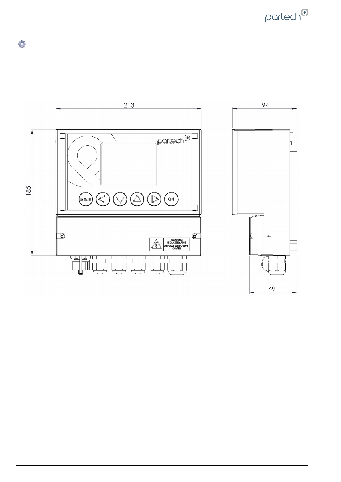
4.1 Mechanical Installation
Monitor external dimensions.
4.2 Installation Considerations
Below are a number of points to be considered when deciding on a final location to install or mount the
8200w² Monitor.
• If the monitor requires regular inspection or local reading of measurements, ensure the monitor is
mounted in a position that allows for easy reading. Consider operators of all heights.
• If the sensor is to be calibrated by a single person, consideration should be paid to the proximity of
the monitor to the sensor. Some sensors require constant monitoring or staged inputs during the
calibration process. This could be difficult if the sensor is remote from the monitor.
• Keep the monitor out of direct sunlight. This can make the display difficult to read, and in extreme
conditions could cause the monitor to overheat and fail.
• Keep the monitor away from other heat sources or electronics that may transmit or radiate
electromagnetic influences.
• Keep the monitor away from mains power cables, variable speed drives and motor controllers.
• The monitor is suitable for the most demanding of environments. Where there is a likelihood of
physical damage, salt-water spray or cleaning by high pressure hoses, we advise the monitor is
installed inside an enclosure for added protection.
Page 10 of 34 229844IM Issue 01 Issue Date 24/06/2019
Page 11
8200w² Monitor Instruction Manual
4.3 Fixings
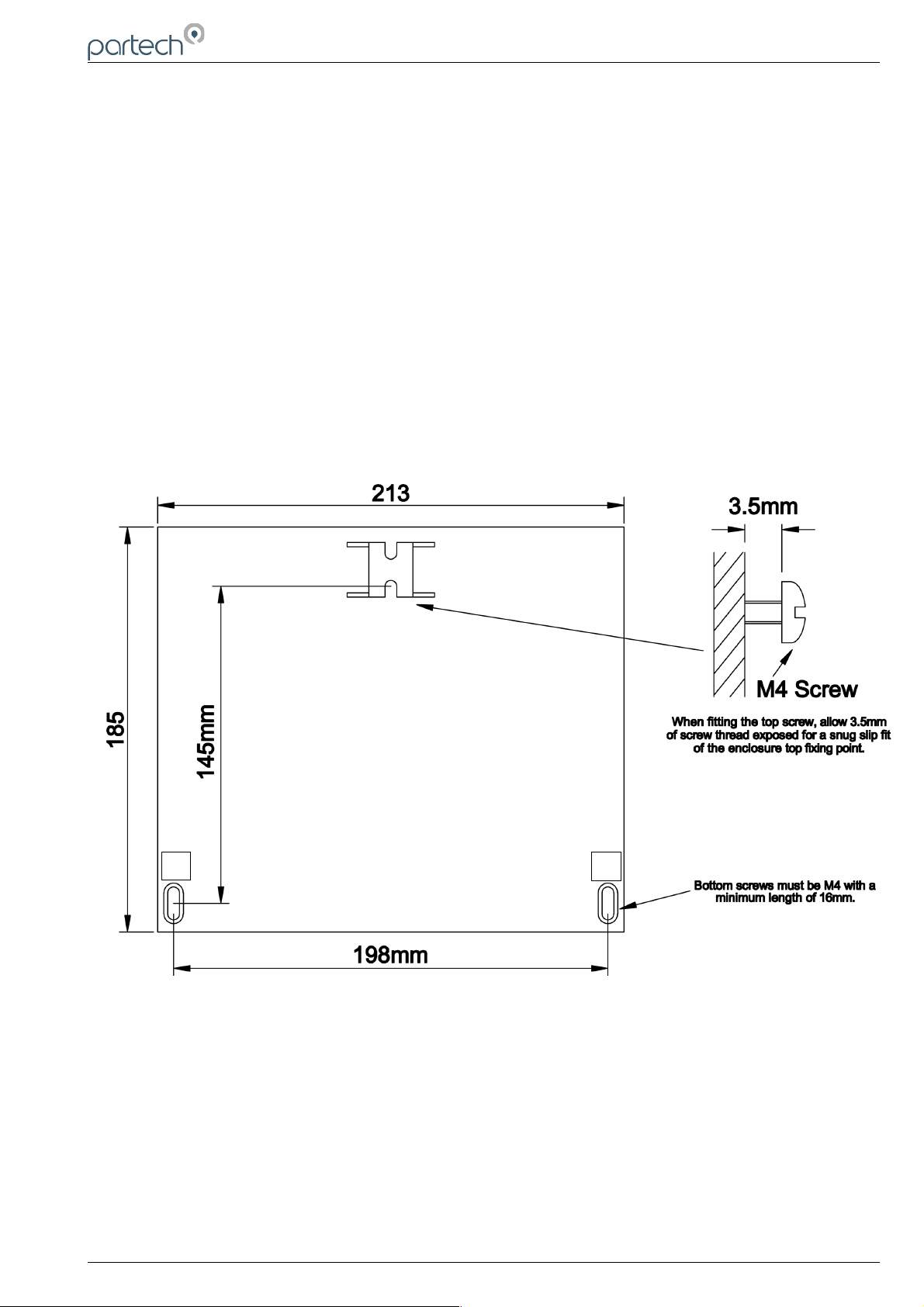
The 8200w² Monitor has 3 fixing points for mounting. Follow these instructions for easy installation and
mounting.
• Offer the monitor up to the final mounting position. Mark the wall behind with a dot halfway along the
top of the enclosure.
• Measure down from the dot 27mm and fit an M4 screw. Ensure the screw has 3.5mm of thread
exposed for a snug fit.
• Hang the enclosure on the screw using the hanging bracket moulded into the back of the monitor
(Loosen the screw if too tight to hang).
• Remove the lower terminal strip cover to reveal the two lower fixing slots (shown as A on the
illustration below).
• Level the Monitor with a spirit level and mark the two lower slots.
• Remove the enclosure and fix drill/tap the above marks.
• Rehang the enclosure (Tighten the top screw if the enclosure feels loose) and fit the two lower
screws. The enclosure has a 14mm shoulder so fixing screws must be at least 16mm long to
penetrate beyond the back of the enclosure.
• Refit the lower terminal cover.
229844IM Issue 01 Issue Date 24/06/2019 ` Page 11 of 34
A
A
Page 12

8200w² Monitor Instruction Manual
4.4 Electrical Installation
Unscrew the two cover screws on the lower panel of the 8200w² Monitor to reveal the Terminals. Each
terminal strip is labelled as illustrated below. (This equipment must be isolated or disconnected from
HAZARDOUS LIVE voltages before access).
The maximum size wire that can be terminated is 2.5mm² CSA. All the connections are via removable
Plug/Socket terminals. To disengage the terminals, simply pull down to release.
Two power options are available for the 8200w² Monitor, AC and DC. Apart from the supply voltage, all other
connections are identical.
4.4.1 Gland Configuration
The 8200w² Monitor is supplied with IP68 Skintop Nylon glands with lock nuts in the following configuration:
• Left: 1 x USB connection
• Centre 4 x M16 glands (4.5-10mm Ø cable)
• Right: 1 x M20 gland (5-10mm Ø cable)
Gland holes are clearance, not tapped. Always blank unused glands to retain the IP rating of the enclosure
Cabling
When selecting and calculating the mains power cable, please note, an ambient temperature of 60ºC may
see a rise to 80ºC within the terminal compartment. This should be considered when making your
calculations, therefore we recommend a power cable with a maximum rating no less than 80ºC.
Recommended cables include H07RN-F, Steel Wire Armoured or YY, CY or SY types (always check
cable data sheets for maximum temperature ratings, as this can vary between manufactures).
Page 12 of 34 229844IM Issue 01 Issue Date 24/06/2019
Page 13

8200w² Monitor Instruction Manual
(Refer to BS7671, section 522 “Selection and erection of wiring systems in relation to external
influences” for guidance).
Shrouded Bootlace Ferrules should always be used when terminating conductors.
4.4.2 DC Power Connections
The DC power connection is a 3 way terminal strip, located furthest right of the termination
bank. The left terminal is the Positive (+) supply, the Right terminal is the Negative (-) or Zero
voltage supply and the centre terminal is the Ground.
The power supply is galvanically isolated from all other terminals on the 8200w² Monitor. It is not
necessary to connect a ground to the monitor,.This terminal has been provided for convenience.
The DC powered 8200w² Monitor is powered typically from a 12V to 24V DC supply.
Min/Max Voltages are 9V to 36V. We do not advise operating the monitors in the field at
voltages approaching the Min or Max values as surges, dips or ripples in supply can fall outside
the Max/Min limits and can cause damage or interruptions to the performance of the 8200w² Monitor.
It is recommended that a circuit protective device (5A Trip) or fuse (5A anti-surge fuse) is fitted to the supply
voltage in close proximity to the monitor and located in a position where it is not difficult to operate, replace
or reset the device. The monitor has an on-board 3.5A fuse for internal protection and is fitted with a reverse
polarity diode.
In addition to the protective device, we advise a local isolator or disconnection switch is fitted in close
proximity to the monitor to allow easy disconnection or isolation of the monitor. This switch should be in easy
reach of the operator and clearly marked as the disconnection device for this equipment. This allows for easy
power-down of the monitor during servicing or periods where the monitor is not being used.
NOTE: If the equipment is used in a manner not specified by this manual, the protection provided by the
equipment may be impaired.
4.4.3 AC Power Connections
The AC power terminal strip is a 3 way connector, located furthest right of the termination bank.
The left terminal is the Earth (E), the Right terminal is the Live supply (L), and the centre
terminal is the Neutral Supply (N).
The AC powered 8200w² Monitor is powered typically from a 100VAC to 240VAC 50/60Hz
supply.
Min/Max voltages are 85VAC to 264VAC, 47Hz-63Hz. We do not advise operating the monitors
in the field at voltages approaching the Min or Max values as surges, dips or ripples in supply
can fall outside the Max/Min limits and can cause damage or interruptions to the performance
of the 8200w² Monitor.
The supply voltage should be fitted with a 3A Type C MCB (the monitor is prone to inrush currents during
initial power up, therefore a “Motor Rated” Type C MCB should be used to prevent nuisance tripping).
It is recommended that a circuit protective device or MCB is situated in close proximity to the monitor, and
located in a position where it is not difficult to operate or reset the device.
In addition to the protective device, we advise a local isolator or disconnection switch is fitted in close
proximity to the monitor to allow easy disconnection or isolation of the monitor. This switch should be in easy
reach of the operator and clearly marked as the disconnection device for this equipment. This allows for easy
power-down of the monitor during servicing or periods where the monitor is not being used.
The monitor should be adequately earthed. Circuit Protective Conductor (Earth conductor) Cross Sectional
Area (CSA) should not be less than the CSA of the calculated phase conductors.
(Refer to BS7671, section 543 “Protective Conductors” for guidance).
NOTE: If the equipment is used in a manner not specified by this manual, the protection provided by the
equipment may be impaired.
All external wiring should comply with local wiring regulations and standards.
The monitor has an insulation resistance of 3KV, however, care should be taken when conducting insulation
resistance tests. We advise the AC terminal strip is disengaged from the circuit board before such tests are
carried out.
229844IM Issue 01 Issue Date 24/06/2019 ` Page 13 of 34
Page 14

8200w² Monitor Instruction Manual
4.4.4 Sensor Connections
When routing the sensor cables, please ensure all cables are separated from any mains cables.
Although the WaterWatch² sensors have a high resistance to interference, separation of mains and
data cables is always good practice and should be followed where practical.
All WaterWatch² sensors and Expansion Boxes communicate with the monitor using the ModTechw²
Protocol. This is a modified Modbus Protocol and has been specifically developed to take advantage
of the advanced features and diagnostics designed into the w² range of sensors.
Note: These sensors can NOT be used with other monitors that are not included in the w² family.
All sensors within the w² family of instruments are connected to the 8200w² Monitor using the same 4 wire
configuration, however some slight variations may occur with specific sensors. Always check the manual
supplied with the sensor to ensure the correct termination is applied.
• RED and BLACK wires provide the 12VDC supply to
the sensor and the communication ground.
• WHITE and GREEN provide data communication.
A maximum of two sensors can be directly connected to the
standard 8200w² Monitor, however additional sensors can be
added using optional Expansion Boxes available separately.
Remove the 4-way connector from the 8200w² Monitor by
pulling downwards to disconnect for easy access to the
connections. Connect the sensor cores as follows:
(Terminals from left to right on the 4 way connector)
Term 1 (Left) - RED (+12V)
Term 2 - Black (0V) and Drain
Term 3 - White (Data A)
Term 4 (Right) - Green (Data B)
Always connect the screen drain wire with the Black (Term 2). Illustration right shows
drain wire and Black wire connected together, and covered in Black Heat shrink.
Always use Bootlace ferrules when terminating the sensors to ensure a good
connection to the terminals.
4.4.5 Extending Sensor Cables
Sensors are usually supplied with 10m cables (longer cables can be provided on request). These cables can
be extended to a maximum length of 100m. To ensure optimum performance, we advise the use of Partech
ModTechw² cable for extensions. Partech can supply Junction Boxes to allow for easy termination of cable
extensions. These should be used on all installations where the cable length from the sensor to the monitor
exceeds 20M (Partech Junction Boxes include on-board filtering for long cable lengths). Junction Boxes are
also useful for local connection of sensors close to the sample point. This permits easier replacement of
sensors without the need to pull back cables to the monitor. The Junction Box has an on-board terminator
switch that can be activated to terminate the network if the sensor is to be removed for long periods.
When joining cables, ensure the connection is fully waterproof. Any moisture ingress can effect the
performance of the sensor and monitor. Always ensure the earth screen is continued when making joints.
ModTechw² Cable specification:
• 2 Twisted Pair: Red/Black (Power) and Green/White (Data) with Screen and Drain wire
• Cores 24AWG (0,22mm²) 7 x 0,20mm
• Outer Insulation: PUR Polyurethane Blue (RAL5003), Diameter – 5mmØ
Page 14 of 34 229844IM Issue 01 Issue Date 24/06/2019
Page 15
8200w² Monitor Instruction Manual
4.4.6 Relay Outputs (Alarms)
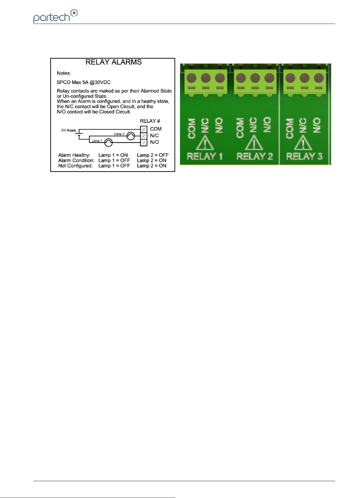
The relay outputs are 3 way terminal strips, located in the middle of the termination bank. The 8200w²
Monitor offers 3 SPCO relay contacts that are user configurable.
Please refer to the “Alarm Configuration” section of this manual for details of how to configure the relays for
alarms or process control outputs.
The relays can switch non-inductive loads up to a maximum of 5A, and withstand voltages up to 240VAC.
Please note, for “Alarm” applications the relays are fail safe. Once configured, the relays will remain
energised in a non-alarmed state (Healthy), therefore N/C will be “Open Circuit”, and N/O will be “Closed
Circuit”. During an Alarm condition, system fault or power failure the relay will de-energise, returning back to
the state illustrated on the label. If the alarm has not been configured, the relay will remain de-energised.
229844IM Issue 01 Issue Date 24/06/2019 ` Page 15 of 34
Page 16
8200w² Monitor Instruction Manual
5 Basic Operation
5.1 Keys and Screen Navigation
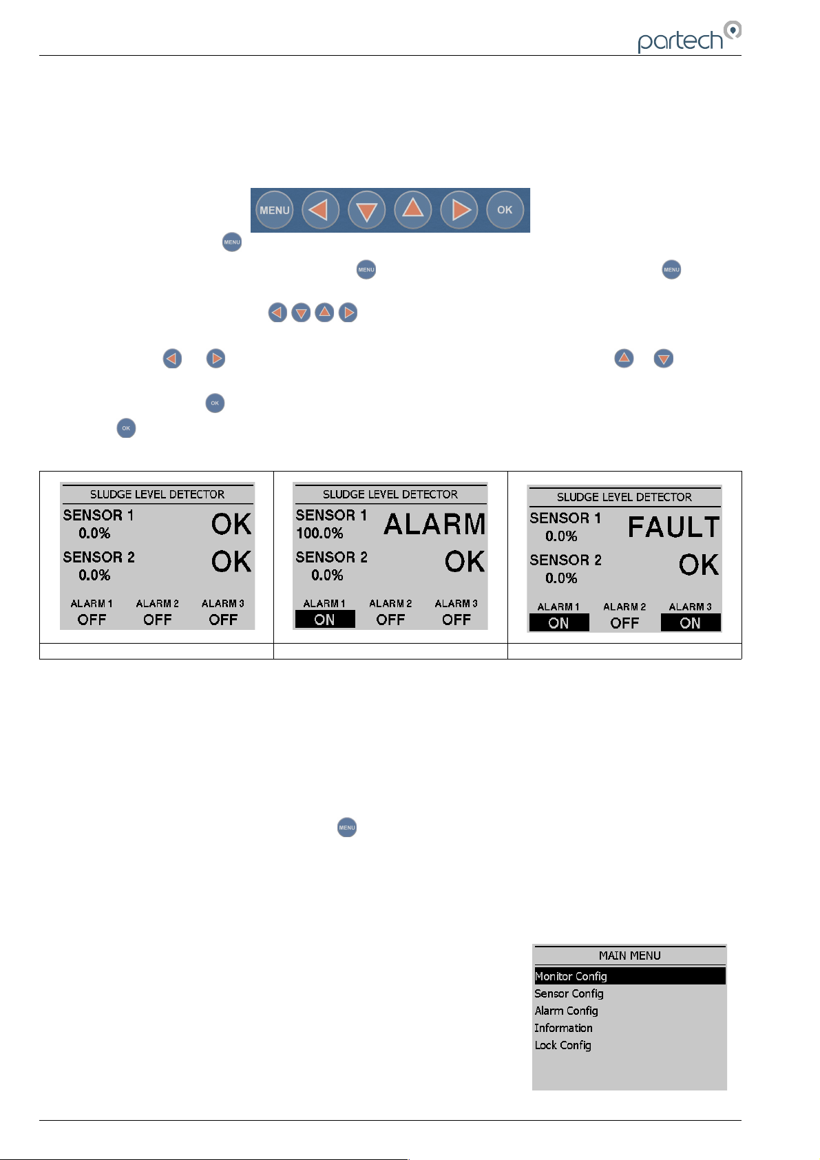
All menus and parameter settings are accessed using the 8200w² Monitor membrane keypad.
5.1.1 Menu Button
From the measurement display screen press to show the Main Menu. While in sub menus, acts as a
return to the previous menu.
5.1.2 Navigation Buttons
Use the navigation buttons to move the cursor up, down or across menus. For example, when setting the
“Time” press or to move the cursor over the number to be changed, and press or to change
the number. These buttons can also be used to change the display screen for multi measurement displays.
5.1.3 OK Button
Press to accept a value or to select a sub menu.
5.2 Measurement Screen
Screenshot 1 Screenshot 2 Screenshot 3
The screen shots above show the 8200w² monitor main display in various conditions.
Screenshot 1 illustrates two sensors installed and no alarms asserted.
Screenshot 2 illustrates sensor 1 has detected the sludge blanket and alarmed. The associated alarm 1
relay will also activate in this example.
Screenshot 3 illustrates sensor 1 with a fault. The associated alarm 1 relay will activate as normal, but in
addition the alarm 3 fault relay will activate
5.3 System Configuration.
From the Measurement Display press to enter the “MAIN MENU”. From this menu, all
configurations and parameters are defined.
Setting up the monitor is a simple and intuitive process. The menu structure has been designed to lead
the operator through the configuration process. Simply start with the menu at the top and work down
through the menus.
Menu options are:
Monitor Config.
Sensor Config.
Alarm Config.
Information
Lock Config.
Page 16 of 34 229844IM Issue 01 Issue Date 24/06/2019
Page 17

8200w² Monitor Instruction Manual
Press or to highlight the menu required, and press to select.
Press at any time to return back to the previous menu.
Note: If no key is pressed for 2 minutes, the monitor will default back to the measurement display
screen.
5.4 Default Configuration
When the Monitor is powered up for the first time, the display will show ‘NO SENSORS’. This indicates
no sensors have been configured. Each sensor must be configured before a value is displayed.
229844IM Issue 01 Issue Date 24/06/2019 ` Page 17 of 34
Page 18

8200w² Monitor Instruction Manual
6 Operational Menus
6.1 Monitor Config Menu
The MONITOR CONFIG menu is used to set up the core monitor
functions, including backlight, bleeper function, time and date. This menu
option also provides access to some advanced configuration and reset
functions.
From the MAIN MENU, ensure MONITOR CONFIG is highlighted (if not,
press or to highlight the option) then press . The six options of
Bleeper, Backlight, Contrast, Language, Date & Time, and Service Mode
are now available.
6.1.1 Bleeper
From the MONITOR CONFIG menu
press or to highlight BLEEPER,
and press to select.
The bleeper (button pressed
acknowledgement bleep) can be turned
on or off as desired. Under normal
circumstances it is preferable to leave the
bleeper turned on as it provides an
audible feedback of key presses and a triple bleep is confirmation that a function has been
successfully changed or selected.
Press or to highlight the option required, and press to select. A tick will appear next to your
selection.
Press to exit this option.
6.1.2 Backlight
From the MONITOR CONFIG menu press or to highlight BACKLIGHT, and press to select.
The backlight can be set to always ON,
always OFF or ON after key press
(backlight will switch off again after a
period of inactivity). There is a marginal
power saving by having the backlight
switched off, otherwise this setting is
down to user preference.
Press or to highlight the option
required, and press to select. A tick
will appear next to your selection.
Press to exit this option.
6.1.3 Contrast
From the MONITOR CONFIG menu
press or to highlight CONTRAST,
and press to select.
The factory setting of 50% should be
sufficient for most ambient light
conditions. For different conditions the
contrast can be altered.
Press or to increase or decrease
the Contrast by 5% (the screen contrast will react with each press of the buttons).
Page 18 of 34 229844IM Issue 01 Issue Date 24/06/2019
Page 19

8200w² Monitor Instruction Manual
Press to exit this option.
6.1.4 Language
From the MONITOR CONFIG menu
press or to highlight LANGUAGE,
and press to select.
The factory default setting is English.
Press or to highlight the option
required, and press to select. A tick
will appear next to your selection.
Press to exit this option.
6.1.5 Set Time/Date
From the MONITOR CONFIG menu
press or to highlight SET
TIME/DATE, and press to select.
Press or to move the cursor
below the digit to be changed.
Press or to increase or decrease
the digit.
Press to accept.
Daylight Savings: The monitor does not automatically update the time to take into account “Daylight
Savings”.
Press to exit this option.
6.1.6 Enable Service Mode
Service mode allows the user access to
diagnostic information and detailed setup parameters. This will normally be
used under the guidance of a Partech
engineer, see section 7.
229844IM Issue 01 Issue Date 24/06/2019 ` Page 19 of 34
Page 20

8200w² Monitor Instruction Manual
6.2 Sensor Config
The monitor leaves the factory with no sensors pre-installed. Before attempting to configure a
measurement, the sensor must be installed. At this stage it is worth reviewing the contents of the
sensor manual(s) to ensure each sensor has been mechanically and electrically installed correctly.
NOTE: Once the Sensors have been wired, unplug each 4-way connector from the 8200w² Monitor or
Expansion Box before powering up the unit. The system must recognise each sensor in turn through
the ModTechw² Protocol in the “Add Sensor Config Menu”.
For further information on the configuration and operation of our sensors
please refer to their relevant manuals supplied with the sensor, please
read both manuals to ensure correct set up and operation. To access the
Sensor Config Menu:
From the MAIN MENU screen, select SENSOR CONFIG by pressing
or to highlight, and press to select.
The SENSOR CONFIG menu should be
displayed. The screen shot on the right,
shows that no sensors have been
installed. The screen shot on the far
right shows both sensors installed.
6.2.1 Sensor Status
From the SENSOR CONFIG menu
press or to highlight, and press
to select. This menu will display a
which of the sensors are installed and
will include the serial number for
reference. Up to 2 sensors can be
configured to a single monitor. If only
one sensor is installed, the remaining
sensor allocation will display ‘NOT
INSTALLED’. The first screen shot on
the right shows the SENSOR STATUS
menu with no sensors installed. The far right with both installed.
6.2.2 Add Sensor
After power up, plug in the sensor(s).
From the MAIN MENU screen, select
SENSOR CONFIG by pressing or
to highlight, and press .
The SENSOR CONFIG menu should be
displayed. Press to highlight the
appropriate NO SENSOR INSTALLED
channel and press .
The S:0x Add option will now be
highlighted. Press and the ‘Are you
sure’ page will be displayed. Press
again and the monitor will now search
for the plugged in sensor.
Once the search is complete, the Monitor will display the sensor found.
Repeat the addition process to install a second sensor. Sensor addition is now complete.
Press to exit this option.
Page 20 of 34 229844IM Issue 01 Issue Date 24/06/2019
Page 21

8200w² Monitor Instruction Manual
6.2.3 S:0x Info
From the SENSOR CONFIG screen, use or to highlight the required sensor. i.e. ‘S:01
SoliTechw² IR (0-200)’, then press to select.
Use or to highlight S:0x Info and press .A tick will appear next
to the identified fault if there is a sensor fault alarm. This function provides
a range of diagnostic information that may be requested by Partech for
fault finding
As can be observed from screenshots on
the right, Page 1 displays sensor type
and sensor serial number. Page 2
displays firmware version and date. The
other two pages display various statuses.
6.2.4 S:0x Averaging
In SENSOR CONFIG press to
highlight the required title and press
to select.
This allows the user to impose averaging
on the measured value, this is used to
reduce the speed of reaction to the
process changes.
The following values are available for the user to select:
Damping Rate Response Time (Seconds) Typical Use
Instant 0.2s Instrument demonstration and test
Very Fast 1s Applications with dynamic solids changes
Fast 10s Normal expected operational use
Medium 30s
Slow 1m
Very Slow 2m Reduce spurious alarms from brief solids changes
229844IM Issue 01 Issue Date 24/06/2019 ` Page 21 of 34
Page 22

8200w² Monitor Instruction Manual
6.2.5 Sensor Removal
If a sensor is no longer required, the sensor configuration can be
removed from the 8200w² monitor in the following way:
From the SENSOR CONFIG screen, use or to highlight the
sensor to be removed; i.e. ‘S:01 SoliTechw² IR (0-200)’, then press
to select.
Use or to highlight REMOVE and press .
Screen will display “Are you sure?”.
Press to remove or to exit
without removing.
6.2.6 S0x Faults
From the SENSOR CONFIG screen, use
or to highlight the required
sensor. i.e. ‘S:01 SoliTechw² IR (0-200)’,
then press to select.
Use or to highlight S:0x FAULTS
and press .A tick will appear next to
the identified fault if there is a sensor
fault alarm.
6.3 Alarm Config (Relay outputs)
The 8200w² monitor leaves the factory with alarms configured but not active. Alarms will be active after
installing the relevant sensor(s). The default condition is OFF.
The ALARM CONFIG menu defines the functions of the 3 relay outputs within the 8200w² monitor.
Alarm relays within the monitor will be shown as “ALARM # (M)”, whereas # denotes relays 1 to 3 and
(M) denotes the monitor.
Important: Alarms 1 & 2 have sensor 1 & 2 measurements allocated to
them respectively. Alarm 3 is the sensor fault relay allocated to both
measurement inputs.
From the MAIN MENU, select ALARM CONFIG and press .
6.3.1 Alarm status
Highlight ALARM STATUS using or
and press .
This screen will show the current status
of the three relays, including type.
Page 22 of 34 229844IM Issue 01 Issue Date 24/06/2019
Page 23
8200w² Monitor Instruction Manual
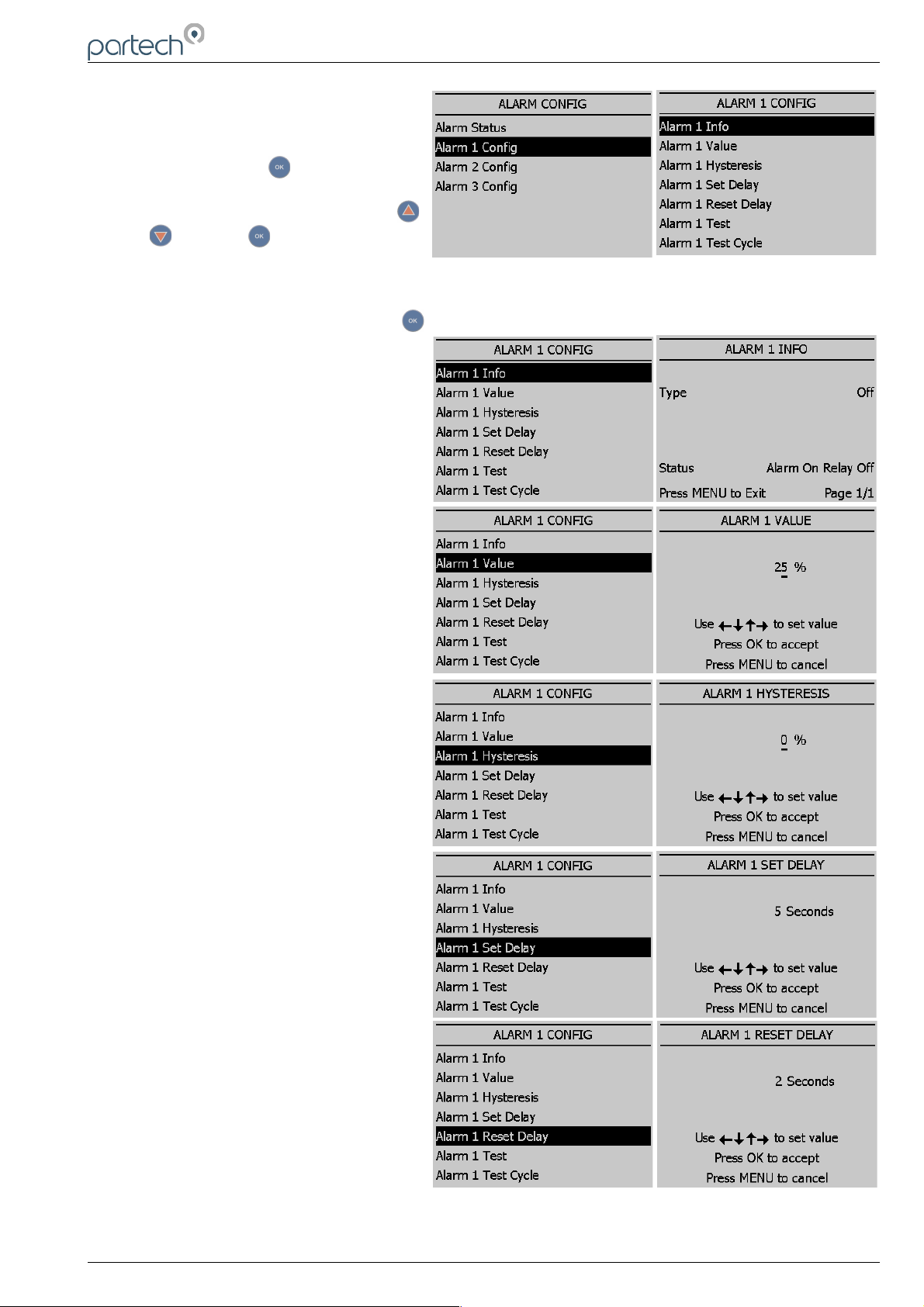
6.3.2 Alarm x Config
From the MAIN MENU, select ALARM
CONFIG and press .
Highlight ALARM (X) CONFIG using
or and press .
A list will be displayed showing the available options to configure the alarm selected.
Highlight the required option and press .
Listed below are the descriptions of each
option. Configure as required.
Info
List configuration details for the alarm.
Value
The alarm set point; the alarm will
activate at a measurement higher than
the actual read sensor value.
Hysteresis
The value entered for Hysteresis is the
dead band where the Alarm will not reset
on a falling value. e.g. A HIGH alarm
value of 50% and a Hysteresis of 5%
would trigger an alarm on a rising value of
50%, but will not reset the alarm until the
reading falls below 45%.
Set Delay
The value entered for the Set Delay is
used to filter spurious measurements and
spikes from giving a false alarm. e.g. for a
HIGH alarm value of 50% and a delay of
10 seconds, the alarm will not activate
until the monitor has read a continuous
measurement of 50% or higher for more
than 10 seconds. If the measurement falls
below 50% during the 10 seconds delay
the timer will reset.
Reset Delay
The reset delay is the opposite to the Set
Delay, whereas the reading must remain
below the set point value for the duration
of the delay before the alarm will reset.
229844IM Issue 01 Issue Date 24/06/2019 ` Page 23 of 34
Page 24
8200w² Monitor Instruction Manual
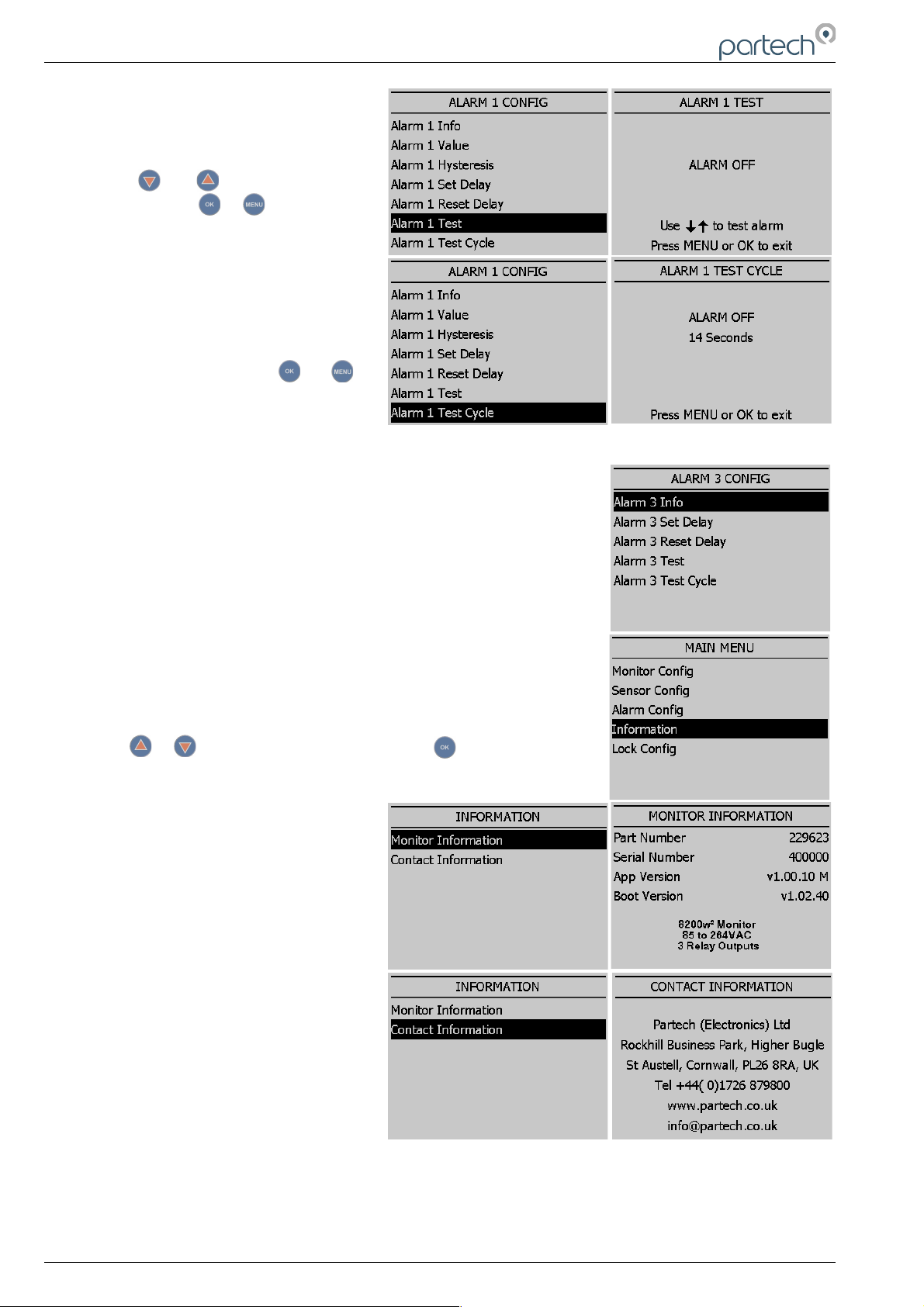
Test
This menu option is for diagnostics use
and allows the operator to test the
alarm/relay by forcing the relay ON/OFF.
Press or to switch the relay
ON/OFF. Press or to exit.
Test Cycle
This menu option is for diagnostic use
and will cycle the alarm relay ON/OFF
every 15 seconds. Press or to
exit.
6.4 Alarm 3 (Fault Alarm)
The menu structure for Alarm 3 is different to Alarm 1 & 2. Alarm 3 is the
general fault alarm that triggers when there is a fault in either sensor 1 or
2. As there is no measurement associated with this alarm the Value and
Hysteresis settings are missing from the menu choice.
6.5 Information
This section provides basic information about the equipment that you
have purchased and contact details for Partech.
From the MAIN MENU, ensure INFORMATION is highlighted (if not,
press or to highlight the option) then press .
6.5.1 Monitor Information
This function displays the installed
software (firmware) versions and the
monitor serial number. Please have this
information available if you need to
contact Partech about this product.
6.5.2 Contact Information
This displays Partech's address, phone
number and website URL.
Page 24 of 34 229844IM Issue 01 Issue Date 24/06/2019
Page 25
8200w² Monitor Instruction Manual
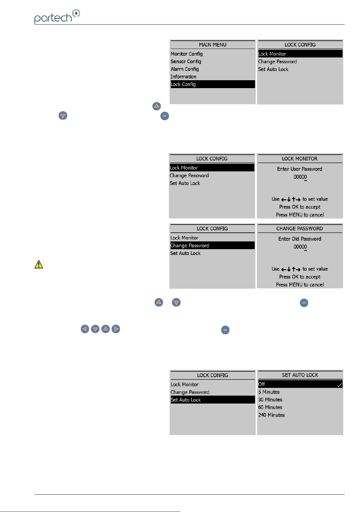
6.6 Lock Config
This function allows the user to restrict
access to all configuration features of
the monitor. This is useful in
circumstances where unintended
adjustment may occur.
From the MAIN MENU, ensure LOCK
CONFIG is highlighted (if not, press
or to highlight the option) then press .
The keypads will allow access to top level functions such as INFORMATION and certain features such
as BACKLIGHT but will not allow adjustment of any setting that effects the measurements being
made. Users will also be able to use the arrow keys to scroll through the different display types.
6.6.1 Lock Monitor
Select LOCK MONITOR to lock. You will
be prompted for a password. The factory
default password is 1000.
Once entered, the monitor is locked.
6.6.2 Change Password
The CHANGE PASSWORD menu allows
the operator to set a user defined
password for menu access.
Care should be taken when changing the
password. If the password is lost, it may
be necessary for Partech to visit the
instrument to unlock the monitor and
reset the password.
From the LOCK CONFIG menu press or to select CHANGE PASSWORD and press .
This screen requests the OLD password. The factory default setting is 1000.
Press the keys to change the password. Press to accept.
You will then be asked to enter the new Password. Repeat the above procedure to set the new
password.
Password is now set.
6.6.3 Set Auto Lock
Two modes of “Lock Instrument” are
available and are configured from this
menu.
Mode 1: AUTO LOCK set to OFF. This is
a “Once Only” lock. If any menu is
accessed that has been locked, the
operator will be required to enter the
password. Once entered the LOCK MONITOR function will be permanently disabled. The monitor
must be manually re-locked again in the LOCK CONFIG Menu if the function is still required.
Mode 2: AUTO LOCK set to 5 mins, 30 mins, 60 mins or 240 mins. This is a temporary unlock
function. If any menu is accessed that has been locked, the operator will be required to enter the
password. Once entered, the LOCK MONITOR function will be temporally disabled for this specified
time. Once this time has elapsed, the monitor will automatically lock again.
229844IM Issue 01 Issue Date 24/06/2019 ` Page 25 of 34
Page 26

8200w² Monitor Instruction Manual
7 Sludge Blanket Level Detection
7.1 Description
The typical sludge blanket level detection installation is in a settlement tank. The system is made up of
a single or dual sensor configuration and a monitor. There will also be associated mounting hardware,
which is dependent upon the applications requirements.
The monitor is typically mounted on a handrail on the bridge of a settlement tank. The sensor is
suspended by its cable; though it should be noted that the sensor must be fastened to the fixing point
provided by the mounting bracket and is not left to hang from the cable gland at the base of the
monitor.
When mounting the monitor and sensor on a settlement tank with rotating bridge, the sensor should
normally be located on the leading edge, approximately half way between the centre and outside edge
of the tank, as shown above. Care should be taken when mounting the sensor to ensure that it does
not trail into the scraper.
7.2 Sensor Installation
Once the bracket/monitor has been attached to the handrail via the saddle clamps and U-bolts and the
sensor has been connected to the monitor, it is then a matter of passing the cable through the various
retaining clamps and lowering it into the settlement tank to the desired depth at which the sludge
blanket is required to be detected. When assessing mounting options, attention should be paid to the
accessibility of the sensor for maintenance, stability of the sensor in the flow conditions present on site
and it must also be ensured that when mounting the sensor it is fully submerged at all times.
The sensor can be suspended by its cable, but the top end of the cable must be fastened to a fixed
point. It should be noted that the sensor must not be allowed to hang direct from the cable gland at the
bottom of the monitor.
7.3 Monitor Configuration
When supplied the factory settings may not be suitable for the required application. If this is the case
then the following procedures should be undertaken. Before adjusting the Alarm value settings, ensure
Page 26 of 34 229844IM Issue 01 Issue Date 24/06/2019
Page 27

8200w² Monitor Instruction Manual
the Alarm x Set Delay and Alarm x Reset Delay are set to zero so the current alarm status is
accurately reported in real time.
7.3.1 Blanket not detected
If the sensor is not detecting the sludge blanket and the OK status remains asserted when the sensor
is in the blanket, take the following action:
With the sensor in the sludge blanket, take note of the % solids value on the display. Enter the Alarm
Config menu and choose the appropriate Alarm x Config option. Set the Alarm x Value to 5% less
than the recorded value. This will ensure the alarm will trigger at the desired % solids. It may also be
advisable to set the Alarm x Hysteresis value to about 5% in order to emphasise a clear boundary
layer.
7.3.2 Blanket continually detected
If the sensor is continually detecting the sludge interface and the ALARM stays on when the sensor is
above the sludge blanket the following action should be taken:
With the sensor above the sludge blanket, take note of the % solids value on the display. Enter the
Alarm Config menu and choose the appropriate Alarm x Config option. Set the Alarm x Value to 5%
greater than the recorded value. This will ensure the alarm will clear at the desired % solids.
Note: If the Alarm x Value is set to 100% and the detector continually indicates the presence of the
sludge blanket when the sensor is above the blanket, the sensor that is fitted is too sensitive and an
alternative sensor will have to be fitted
For an accurate adjustment of the Alarm x Value to a required level:
1. Immerse the sensor fully in a known sample of the required value.
2. Record the % solids value on the display.
3. Enter the Alarm Config menu and choose the appropriate Alarm x Config option. Set the Alarm x
Value to 5% less than the recorded value.
The desired alarm point has now been set and the controller will now detect sludge blankets of this
value or higher.
Note: In the event of the sensor being changed, it will be necessary to repeat the above alarm point
adjustment in order to obtain accurate results
229844IM Issue 01 Issue Date 24/06/2019 ` Page 27 of 34
Page 28

8200w² Monitor Instruction Manual
8 Menu Tree
Below is the menu structure of the 8200w² Monitor:
Main Menu
Monitor Config
Bleeper
Backlight
Contrast
Language
Set Date/Time
Enable Service Mode
Sensor Config
Sensor Status
S:0x Sensor Type Option
S:0x Info
S:0x Averaging
S:0x Remove
S:0x Faults
Alarm Config (# = refers to 1 - 2)
Alarm Status
Alarm # Config
Alarm # (M) Info
Alarm # (M) Value
Alarm # (M) Hysteresis
Alarm # (M) Fault Setup
Alarm # (M) Set Delay
Alarm # (M) Reset Delay
Alarm # (M) Test
Alarm # (M) Test Cycle
Alarm 3 Config
Alarm # (M) Info
Alarm # (M) Set Delay
Alarm # (M) Reset Delay
Alarm # (M) Test
Alarm # (M) Test Cycle
Information
Software Version
Contact Information
Lock Config
Lock Monitor
Change Password
Set Auto Lock
Page 28 of 34 229844IM Issue 01 Issue Date 24/06/2019
Page 29
8200w² Monitor Instruction Manual
9 Maintenance
9.1 On-Board Battery Backup Replacement
The monitor is fitted with a battery backup for the real time clock function. Failure of the battery will
only effect the time (all parameters, settings and process data are stored electronically and is not
effected by a failed battery).
Fitted is a Lithium CR2032 battery. Under normal operating conditions, the battery should not require
replacement for at least 5 years. However, we advise the battery is replaced if the monitor has been
kept in storage or remained off power for more than 3 years.
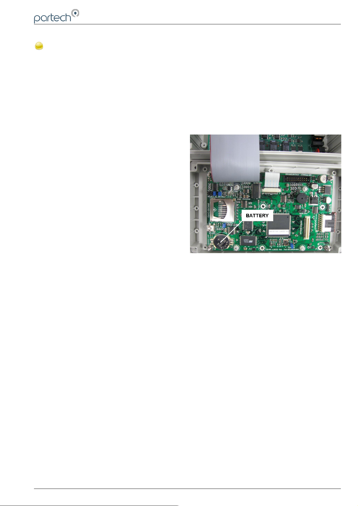
The battery is located behind the main display panel. To access the battery, follow these steps.
1, Ensure the monitor is isolated or disconnected
from HAZARDOUS LIVE voltages before access.
2, Remove the four plastic caps located on the
corners of the display using a small flat bladed
screwdriver to reveal the screws.
3, Unscrew the four screws and gently lower the
panel. Take care as the display is connected to the
back board via a ribbon cable.
4, With the display panel turned over and hanging
upside-down by the ribbon cable (see photo right),
the battery can be located on the bottom left corner
of the display board. Disconnect the ribbon cable if
this makes access easier.
5, Using a flat bladed screwdriver, gently prise out
the battery and replace.
6, Return the display panel back to the enclosure (first reconnect the ribbon cable if disconnected),
and screw back. Refit the screw covers.
7, Reset the Monitor time as described in section 6.1.4 of this manual.
229844IM Issue 01 Issue Date 24/06/2019 ` Page 29 of 34
Page 30

8200w² Monitor Instruction Manual
10 Technical Support
Technical Support is available by phone, fax, or email, the details of which are shown below.
• Phone: +44 (0) 1726 879800
• Fax: +44 (0) 1726 879801
• Email: [email protected]
• Website: www.partech.co.uk
To enable us to provide quick and accurate technical support please have the following information ready
when you contact us:
• Serial Number or original purchase details.
• Sensor Type, and Serial Number.
• Application details.
• Description of fault.
• Digital photos can also be useful to determine correct installation and suitability to the application.
10.1 Returning Equipment for Repair
If equipment needs to be returned to Partech for repair or service the following address should be used:
SERVICE DEPARTMENT
PARTECH INSTRUMENTS
ROCKHILL BUSINESS PARK
HIGHER BUGLE
ST AUSTELL
CORNWALL
PL26 8RA
UNITED KINGDOM
Please include the following information with the returned equipment. Also ensure that sensor is clean and
adequately protected for transportation (Advice on packing can be provided by our service department).
• Contact name and phone number of person authorising the repair
• Site details including application sample point
• Return address for equipment
• Description of fault or service required
• Any special safety precautions because of nature of application
Page 30 of 34 229844IM Issue 01 Issue Date 24/06/2019
Page 31

8200w² Monitor Instruction Manual
11 Technical Specification
11.1 Physical
Dimensions ....................................213 x 185 x 95mm (HxWxD)
Enclosure Material..........................Polycarbonate (PC)
Weight.............................................1.4Kg
Temperature....................................-20 to +60 C, 0-95% Relative Humidity, Non-Condensing
Mounting......................................... Wall or Rail Mounting Bracket or Enclosure Option Available
Cable Entries...................................1x M20, 4x M16, 1x M12
11.2 User Interface
Display ...........................................Graphic LCD, Black on White, Transreflective
Viewing Area...................................78 x 59mm
Backlight..........................................Always ON / OFF, User Adjustable ON/OFF after key press
Membrane Keypad..........................High quality 6 key membrane with Pillow Embossed 20mm dia Buttons
11.3 Electrical
Operation Voltage: .........................100 to 240VAC, 50/60Hz
or 12 to 24VDC
Power Rating...................................0.8A AC, 30W DC (Power consumption may increase for 2 or more sensors)
Terminal Wire Size..........................Max 2.5mm² cores
Digital/Relay Outputs......................3 (Reduced to 1 Relay for PROFIBUS)
Relay Type......................................SPCO, Max 230VAC Switching Voltage
Relay Rating....................................Max 5A @ 30VDC / 230VAC
Auxiliary Connections......................Configurable for remote Input, Output or 12VDC Aux Power
11.4 Sensors and Optional Interfaces
Sensor Communication...................ModTechw² Protocol (Specifically developed for w² range of sensors)
ModTechw² Cable Specification......2 Twisted Pair (Red/Black, Green/White), 24AWG screened with drain wire
229844IM Issue 01 Issue Date 24/06/2019 ` Page 31 of 34
Page 32

8200w² Monitor Instruction Manual
229844IM Issue 01 Issue Date 24/06/2019 ` Page 32 of 34
Page 33

8200w² Monitor Instruction Manual
229844IM Issue 01 Issue Date 24/06/2019 ` Page 33 of 34
Page 34

Partech Instruments
Rockhill Business Park, Higher Bugle, St Austell, Cornwall,PL26 8RA,UK
Tel: +44(0)1726 879800
Email: [email protected] Web: www.partech.co.uk
 Loading...