

Parsun F4ETS, F4ETl, F4ERS, F4ERL Operating Manual

ELECTRIC OUTBOARD MOTOR
OPERA T OR’S MANUAL
Model Numbers
F4ETS, F4ETL, F4ERS, F4ERL
SUZHOU PARSUN POWER MACHINE CO., LTD.

Thank you for purchasing a PARSUN outboard motor.
Your trust in our company and products is greatly appreciated
“PARSUN” outboard motors are powerful, economic, safe, and manufactured
with advanced technology.
Please read this manual carefully before operating your outboard motor. A
through understanding of the manual will help you to safely operate the product, and
perform the required maintenance and care. By following the information contained
within this manual, you will ensure that your outboard motor operates for many years
“PARSUN” seeks continuous improvement in product quality. Therefore,
while this manual contains the most current product information available at the time
of printing, there may be minor discrepancies between your machine and this manual.
If there is any question concerning the manual, please consult your local PARSUN
dealer.
Data, illustrations, or explanations in this Operators Manual do not constitute
base for any legal claim against our company.
SUZHOU PARSUN POWER MACHINE CO., LTD
Outboard Identification Numbers
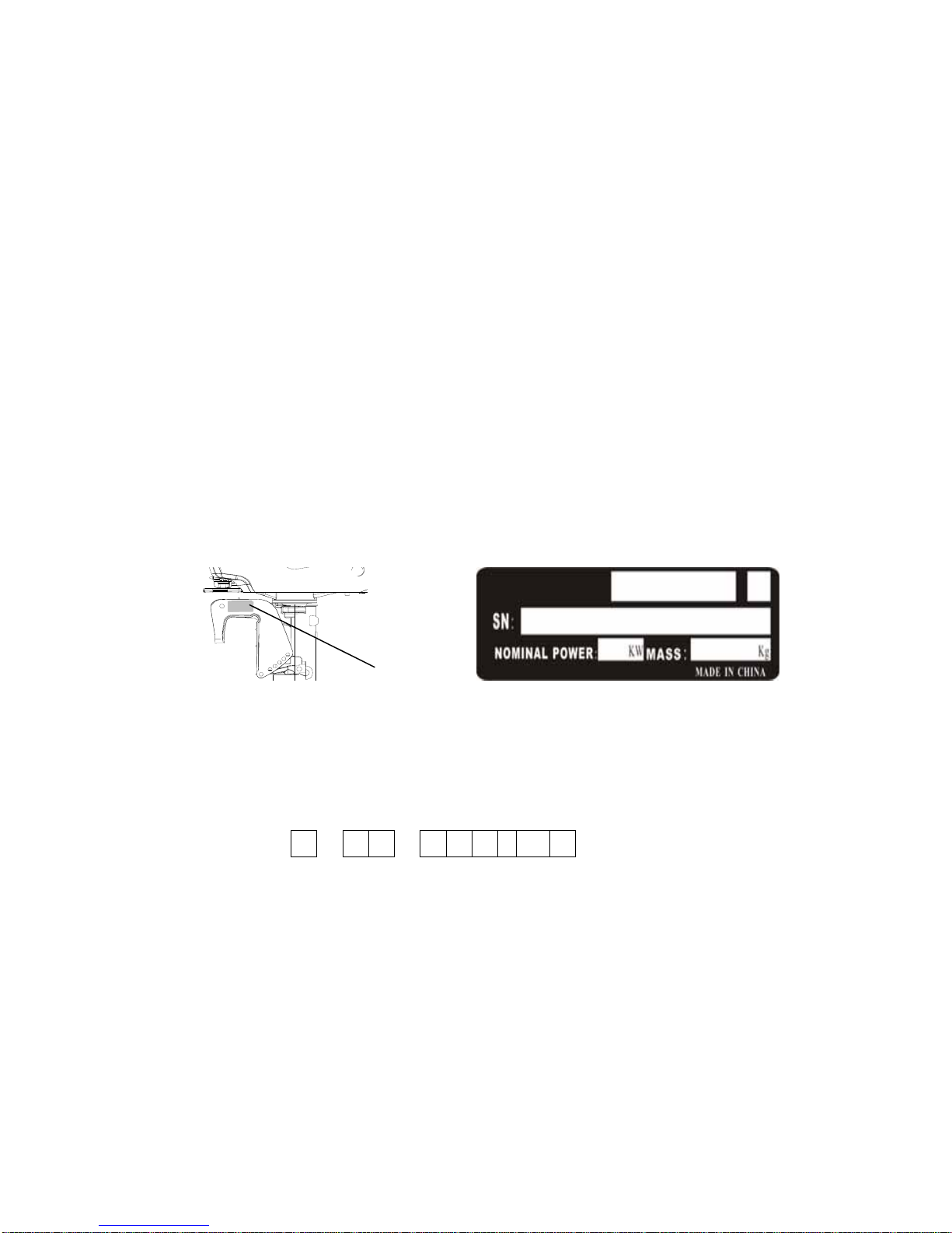
Outboard motor serial number
The outboard motor serial number is marked on the label. The label can be found on the left bracket
assembly or on the upper part of the bracket swivel.
Record your outboard motor serial number in the spaces provided to assist you in ordering spare
parts from your Parsun dealer or for reference in case your outboard motor is stolen.
1
1. Outboard motor serial number location.
Serial number as follows:
N S

Manufacturer’s Declaration
This outboard motor complies with the requirements of Directive 2003/44/EC in relation to the noise
emissions. The following installation and maintenance instructions, if applied, guarantee that the
outboard motor will remain in compliance with the noise emissions limits under normal conditions of
use.
Table of contents Page
Main Components and General Information……………………..……..……………….…1
General Information and Specifications…………………………………………………….2
Propeller Selection….…………………………………………………….…………………..3
Installation and Operation..…….………………………………….…………..……………..3
Mounting Height Recommendations…….………………………………………………….5
Clamping the Outboard Motor……………….………………………………………………6
Pre-Operation Checks………………………………………………………………….…….8
Starting the Outboard (Tiller Model)………………………….………………….………… 9
Changing Direction for Tiller Model………………………..…………….….……………..11
Stopping the Outboard (Tiller Model…………………………………………….…….......12
Throttle Friction Adjuster………………………………………………….………..............13
Starting the Outboard (Remote Control Model)……………………………....................14
Changing Direction for the Remote Control Model……..…………..……….………......15

Stopping the Remote Controlled Outboard..……………………………….……….…...16
Trimming the Outboard Motor…………………………………………………………......17
Tilting Up and Down (Warnings)……………………………………………………..…....18
Tilting Up………………………………………………………………….………………….19
Tilting Down………………..………………………………………………….…….……….20
Cruising in Shallow Water/Salt Water………………..……………………………………21
Maintenance Procedures………………..………...………..……………………………...22
Greasing ………………..…………………….…………………………………….............23
Checking the Propeller………………..…………………………………………….…......24
Removing/Installing the Propeller………………..………………………………….........25
Changing the Gear Oil………….………………..……………………………………….. 26
Checking and Replacing the Anode…………………………………………......…..…...28
Checking the Top Cover……………………………………….…….…………..….......... 29
Maintenance Table……………………………………..……………………….….…….....29
Transporting and Storing……………………………………..……………………….……32
Emergency Situations………..……………………….….……........................................34
Treatment of Submerged Outboard………………………..……………………….….….34
Low Battery Warning Buzzer……………………………………………………………….34
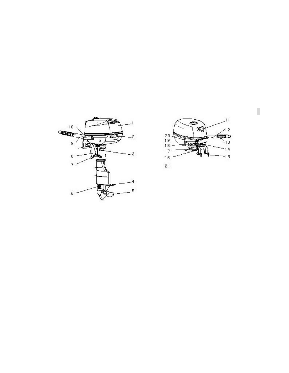
Main Components and General Information 1
1. Top cover
2. Top cover lock handle
3. Steering friction screw
4. Anti-cavitation plate
5. Propeller
6. Cooling water inlet
7. Trim Rod
8. Clamp Bracket
9. Tiller handle
10. Stop button, Lanyard switch
11. Control switches
12. Throttle friction adjuster
13. Throttle grip
14. Carry handle
15. Clamp screw
16. Rope attachment
17. Tilt support bar
18. Remote control cable
19. Power Cable connector

General Information and 2
Specifications
Parameter
Items Data Items Data
Type of outboard Electric Input Power 4.8 KW Maximum
Rated voltage 48 VDC
Maximum Continuous
output
3.0 Kw/4500Rpm
(4HP)
Rated Current 100 Amps Full throttle motor speed
4000~5000Rpm
Operating Voltage 30-60 VDC Gear ratio
2.08(27/13)
Overall length 717mm Recommended gear oil
Hypoid gear oil SAE﹟90
Overall width 361mm Gear oil quantity 100 mm
3
Overall height (S) 1029mm ETL:30.4kg,ETS:29.4kg
Overall height (L) 1156mm
Net Weight
ERL:29.4kg,ERS:28.4kg

3
Propeller Selection
The performance of your outboard motor will be critically affected by your choice of propeller, as
an incorrect choice could adversely affect performance. The outboard motor is fitted with propeller
chosen to perform well over a range of applications, but there may be uses where a propeller with a
different pitch would be more appropriate. “PARSUN” dealers stock a range of propellers and can
advise you and install a propeller on your outboard that is best suited to your application.
For a greater boat load and a low engine speed, a smaller-pitch propeller is more suitable.
Conversely, a large-pitch propeller is more suitable for a smaller operating load as it enables the
correct engine speed to be maintained.
Operation and
Installation
Mount the outboard motor on the center line (keel line) of the boat. For boats without a keel or
which are asymmetrical, consult your dealer.
1
1. Center line (keel line)

4
NOTE:
During water testing, check the buoyancy of the boat when at rest with its maximum load.
Check that the static water level on the exhaust housing is low enough to prevent water entry
into the power head, or when water rises due to waves, or when the outboard is not running.
WARNING:
Overpowering a boat could cause severe instability. Do not install an outboard motor
with more horsepower than the maximum rating on the capacity plate of the boat. If the
boat does not have a capacity plate, consult the boat manufacturer.
Improper mounting of the outboard motor could result in dangerous conditions and injury.
For permanently mounted models, your dealer or other person experienced in proper
rigging should mount the motor. If you are mounting the motor yourself, you should be
trained by an experienced person. For portable models, your dealer or other person
experienced in proper outboard motor mounting should show you how to mount your
motor.
The information presented in this section is intended as reference only. Proper mounting
depends in part on experience and the specific boat and motor combination.

5
Mounting Height
0~ 25mm
(0-1in)
The mounting height of the outboard motor greatly affects your boat running efficiency. If the
mounting height is too high, cavitation tends to occur, thus reducing the propulsion. If the mounting
height is too low, the water resistance will increase and thereby reduce engine efficiency. Mount the
outboard motor so that the anti-cavitation plate is between the bottom of the boat and a level 25mm
below it.
NOTE:
The optimum mounting height of the outboard motor is affected by the boat and motor
combination and the desired use. Test runs at a different height can help determine the
optimum mounting height. For further information, consult your “PARSUN” dealer or boat
manufacturer.

6
Clamping the Outboard Motor
1.
Tighten the transom clamp screw evenly and securely. Occasionally check the clamp screws
for tightness during operation of the outboard motor because they could become loose due to engine
vibration.
WARNING:
Loose clamp screws could allow the outboard motor to fall off or move on the transom.
This could cause loss of control. Make sure the clamp screws are tightened securely.
Occasionally check the screws for tightness during operation.

7
1. If the engine restraint cable attachment is equipped on your engine, an engine restraint cable or
chain should be used. Attach to a secure mounting point on the boat to avoid the engine being
completely lost if it accidentally falls off the transom.
 Loading...