

Parsun F25/20BM, F25/20BW, F25/20FW Owner's Manual

OUTBOARD MOTOR
OWNER’S MANUAL
F25/20BM
F25/20BW
F25/20FW
SUZHOU PARSUN POWER MACHINE CO., LTD

Thank you for owning a PARSUN outboard motor.
Thank you for your trust in our company and products.
“PARSUN” outboard motors are powerful, economic and safe, manufactured with
advanced technology.
Please read this manual carefully before operating your outboard motor. A
through understanding of the manual will help you to know this product for proper
operation, maintenance and care. This will ensure that your outboard motor operates
well under all conditions.
“PARSUN” seeks continuous improvement in product quality. Therefore, while this
manual contains the most current product information available at the time of printing,
there may be mi nor disc rep anci es bet ween y our m achin e and thi s manu al. If there is any
question concerning the manual, please consult your local PARSUN dealer.
Data, illustrations or explanations in this Owner’s Manual do not constitute base for
any legal claim against our company.
SUZHOU PARSUN POWER MACHINE CO., LTD
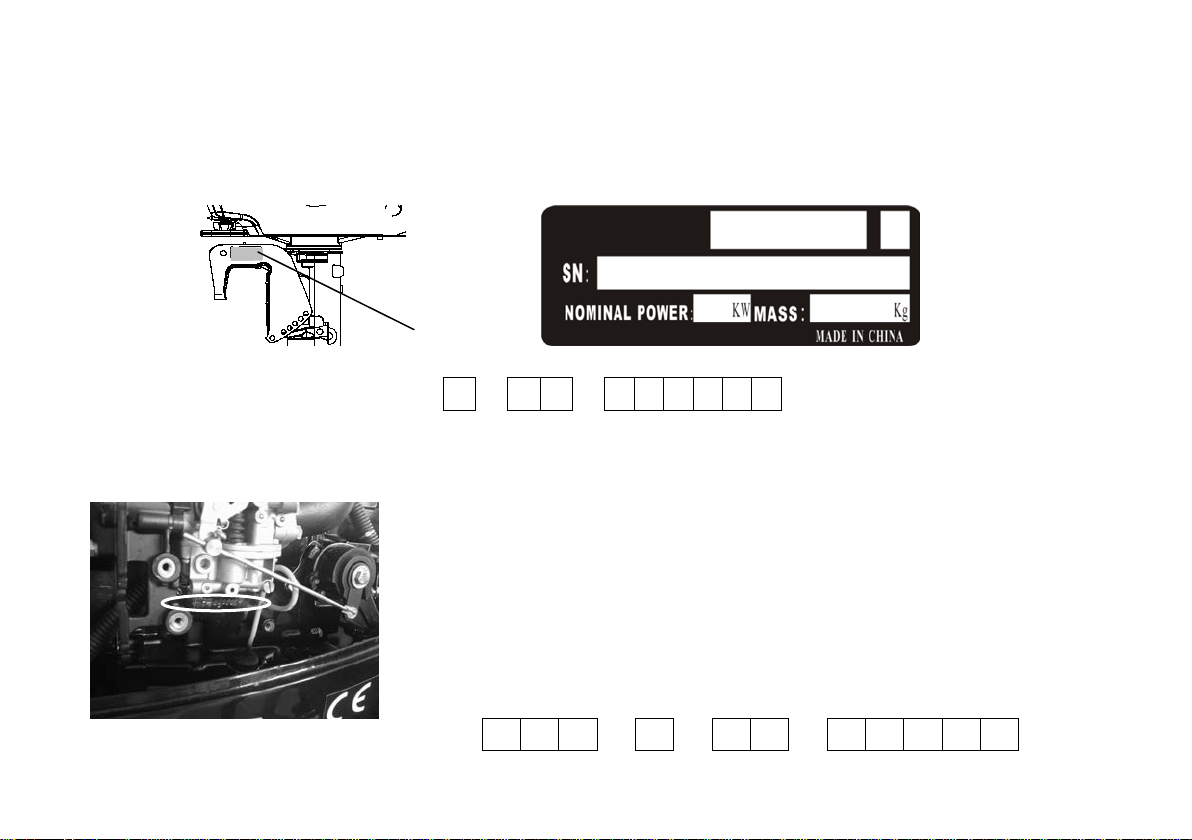
Engine Identification Numbers
SN
1
Outboard motor serial number
The outboard motor serial number is marked on the label. The label can be found on the bracket left
assembly or on the upper p ar t of the br acket swivel.
Record your outboard motor serial nu mber in the sp aces prov ided to assist y ou in ordering sp are p arts fr om
your dealer or for reference in case your outboard motor is stolen.
1. Outboard motor serial nu mb er loc ation
Serial number as follows:
Engine serial number
The engine serial number is carved on the aluminum casting of engi ne.
Engine serial number as f oll ow s:

Manufacturer’s Declaration
This outboard motor complies with the requirements of Directive 2003/44/EC in relation to the exhaust and
noise emissions. The following installation and maintenance instructions, if applied, guarantee that the
outboard motor will rema i n in compliance with:
1. Exhaust emissions limits throughout the normal life or the engine (350 hours or 10 years, whichever
occurs first) and under normal conditions of use.
2. Noise emiss io ns l i mits under normal conditions of u se.
High Altitude Warning
Operation at High Altitude
The density of air at high altitude is lower than at sea level. Engine power is reduced as the air mass
and air fuel ratio decrease. Outboard motor output will be reduced. This is a natural trend and cannot
be changed by adjusting the engine. At sufficiently high altitudes increased exhaust emissions can
also result due to the increased enrichment of the air fuel ratio. Other high altitude issues can include
hard starting, increased fuel consumption and spark plug fouling.
To alleviate high altitude issues other than the natural power loss, dealer can provide a high altitude
carburetor main jet. The alternative main jet and installation instructions can be obtained by contacting
Customer Support.
The part number and recommended minimum altitude for the application of the high altitude carburetor
main jet are listed in the table below.

WARNING
MODEL MAIN JET PART NUMBER ALTITUDE
F20/25
Standard Main Jet H177-S
2000 Feet (609.6 Meters)
Altitude Main Jet H177×1.08
Operating the engine with the wrong engine configuration at a given altitude may increase its
emissions and decrease fuel efficiency and performance. When the carburetor has been
modified for high altitude operation, the air-fuel mixture will be too lean for low altitude use.
Operation at altitudes below 609.6 meters (2,000 feet) with a modified carburetor may cause the
engine to overheat and result in serious engine damage. For use at low altitudes, have your
dealer return the carburetor to original factory specifications.

Table of contents
1. Main components a n d Ge ne ra l i n formation......... .. .... .. . .................................................................1
1.1. Main components..................................................................................................... ................1
1.2. General informat io n .............. ............... ........................... ............... ........................................... 2
1.2.1. Specification.........................................................................................................................2
1.2.2. Fueling instructions...............................................................................................................3
1.2.3. Propeller selection................................................................................................................4
2. Operation.......................................................................................................................................5
2.1. Installation.................................................................................................................................5
2.1.1. Mounting height................ .....................................................................................................5
2.1.2. Clamping the outboard mo tor................................... ............................ ..................................6
2.2. Breaking in engine.....................................................................................................................7
2.3. Pre-operation Checks................................................................................................................8
2.4. Filling fuel................................................................................................................................10
2.5. Starting engine............. ............... ............... ........................... ............... ...................................10
2.6. Warming up engine.......... ............... ........................... ............... ............... ...............................19
2.7. Shifting....................................................................................................................................19
2.7.1. Forward................................................................................................................................20
2.7.2. Reverse................................................................................................................................21
2.8. Tiller.........................................................................................................................................22
2.9. Trim tab...................................................................................................................................24
2.10. Stopping engine.................................... ............... ............... ...................................................24

2.11. Trimming outboard motor........................................................................................................26
2.12. Tilting up and down................................................................................................................27
2.12.1. Tilting up........................... ............... ........................... ............... ............... ...........................27
2.12.2. Tilting down....................................... ............... .............. ............................ .........................30
2.13. Cruising in other conditions...................... ........................... ............... ....................................31
2.13.1. Cruising in shallow wat er..................................... ............... .................................................31
2.13.2. Cruising in salt water....................... ............... ........................... ............... ...........................32
3. Maintenance................................................................................................................................33
3.1. Greasing..................................................................................................................................33
3.2. Cleaning and adjusting spark plug..........................................................................................34
3.3. Checking fuel system..............................................................................................................34
3.3.1.
Cleaning fuel filter...............................................................................................................35
3.4. Inspecting idling s p eed............. ............................ ............... ........................... .........................36
3.5. Changing engine oil.................................................................................................................37
3.6. Checking wiring an d co nn e c tors........... ............................ .............. ........................................38
3.7. Checking leakage............... ............................ .............. ............................ ..............................38
3.8. Checking propeller.......... ............................ .............. ............................ ..................................38
3.8.1. Removing the propeller......... ............... ........................... .............. .....................................39
3.8.2. Installing the propeller......... ............... ........................... ............... ......................................40
3.9. Changing gear oil....................................................................................................................40
3.10. Cleaning fuel tank...................................................................................................................41
3.11. Checking and replacing a no d e (s)......................... ............... ........................... ....................... 42

3.12. Checking top cowling............... ............................ ...................................................................42
3.13. Maintenance table................. ............... ........................... ............... .......................................43
4. Transporting and storing outboard motor...................................................................................45
4.1. Transporting............................................................................................................................45
4.2. Storing.....................................................................................................................................46
5. Action in emergency........................................... .............. ............................ ...............................48
5.1. Impact damage.......................................................................................................................48
5.2. Starter will not operate.......... ............................ .............. ............................ ............................48
5.3. Treatment of submerged motor........................................ .............. ........................................50
6. Troubleshooting...........................................................................................................................51
7. Circuit diagram............................................................................................................................55
1. Main components and General information
22
11
6
19
20
21
18
17
14
15
16
13
12
10
9
8
7
5
4
3
2
1
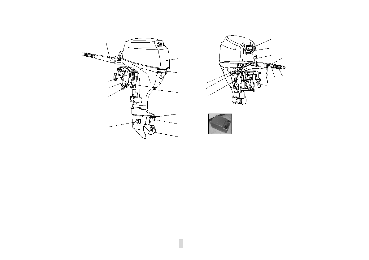
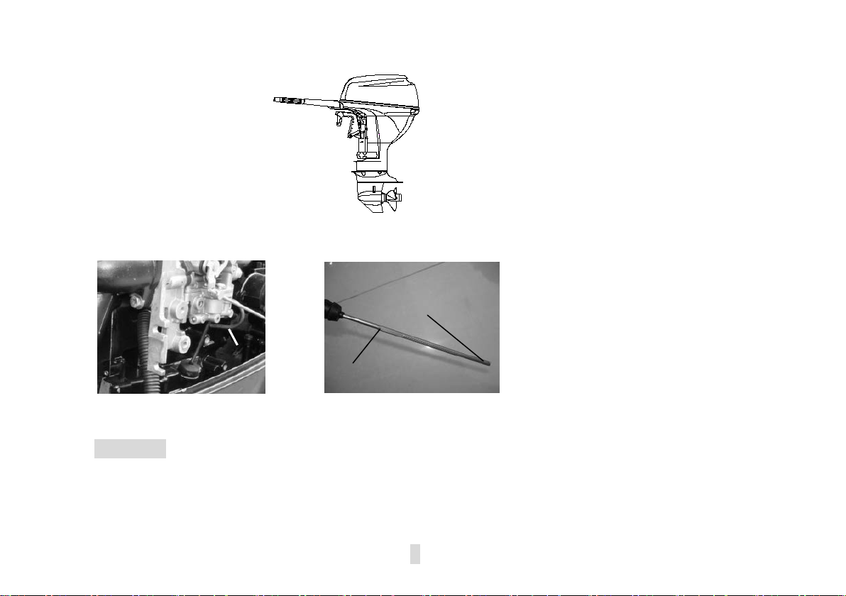
1.1 Main components
1. Top cowling 9. Clamp bracket 17. Throttle grip
2. Top cowling lock handle 10. Steering friction bolt 18. Clamp bolt
3. Drain screw 11. Tiller handle 19. Rope attachment
4. Anti-cavitation plate 12. Starter s handle 20. Tilt lock lev er
5. Trim tab 13. Warning indicator 21. Fuel joint
6. Propeller 14. Gear shift lever 22. Fuel tank
7. Cooling water inlet 15.
8. Trim rod 16. Throttle frication adjuster
Engine stop button/Engine stop lanyard switch
1
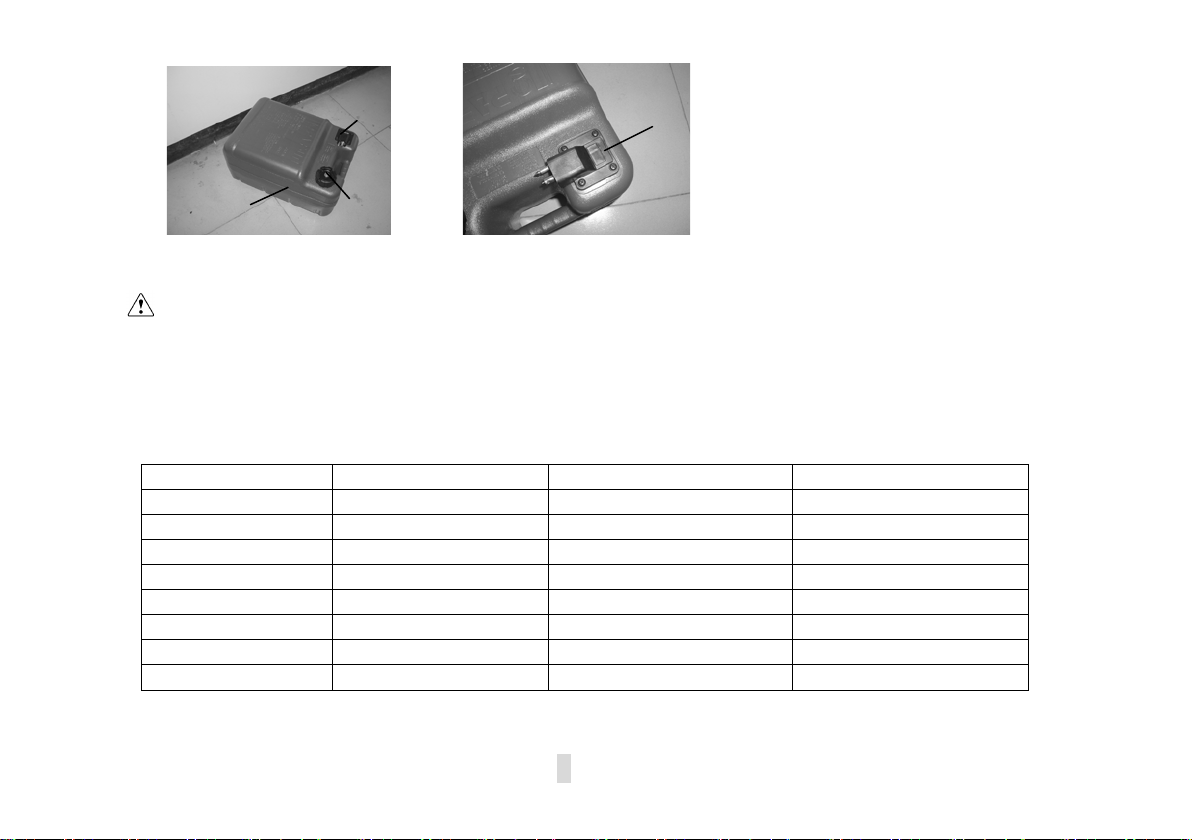
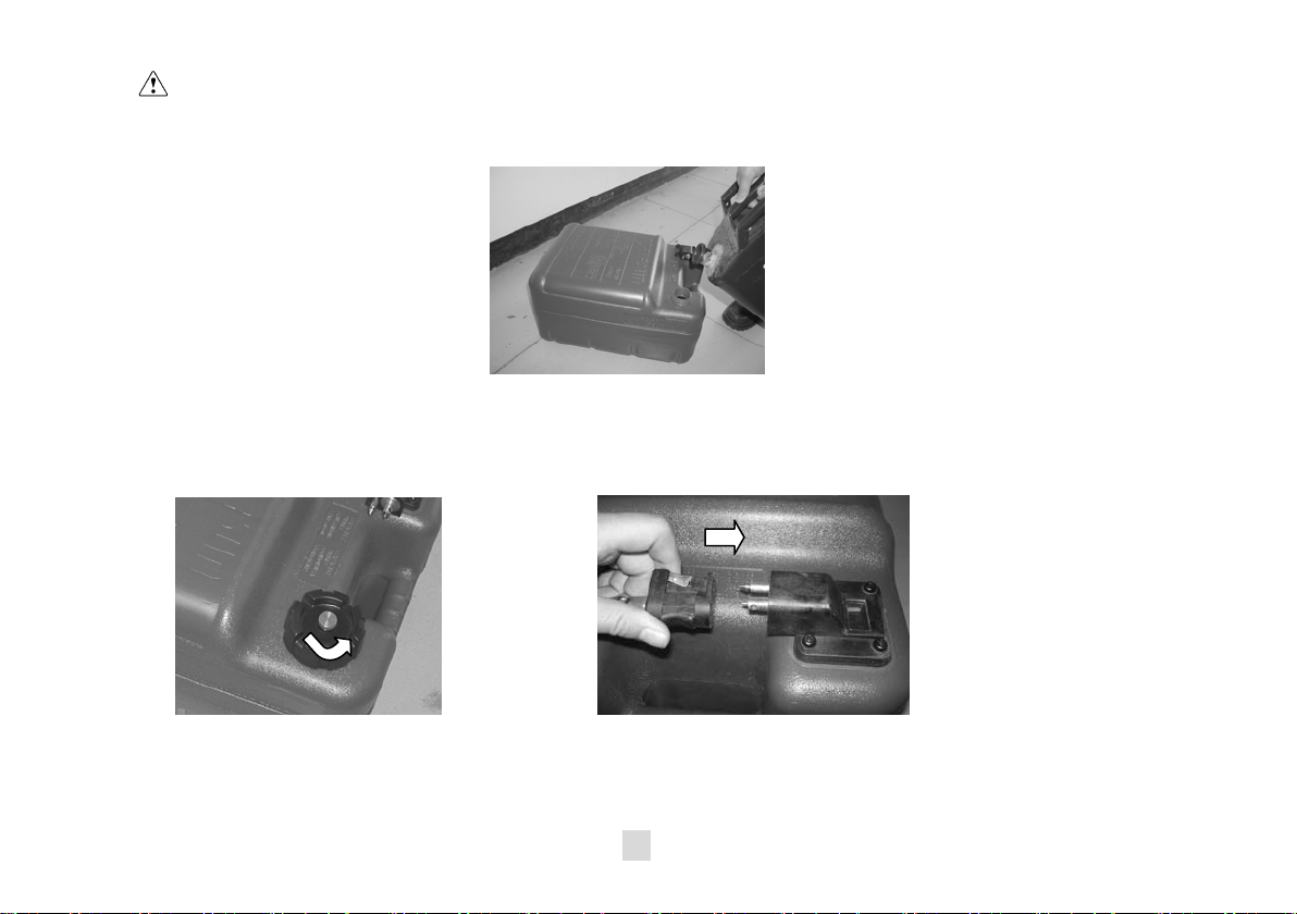
A portable fuel t a nk includes parts as follows:
Items
Data
Items
Data
Type of engine
4-stroke L
Weight (L/S/WL/WS)
68Kg/66Kg/70Kg/68Kg
Displacement
498cm3
Recommended fuel
Unleaded regular gasoline
Bore X stroke
65mm×75mm
Fuel tank capacity
24L
Gear ratio
2.08(27/13)
Recommended engine oil
SAE10W30 or SAE10W40
Overall length
1151mm
Engine oil quantity
1.7L
Overall width
430mm
Recommended gear oil
Hypoid gear oil SAE﹟90
Overall height (L/S)
1280mm/1153mm
Gear oil quantity
320cm3
Transom height (L/S)
508mm/381mm
Spark plug
DPR6EA-9
1
2 4
3
1. Fuel tank cap 3. Air vent screw
2. Fuel joint 4. Fuel gauge
WARNING:
The fuel tan k supplier with this engi ne could only be used as supply of fuel for it’s running and
must not be as a fuel storage container.
1.2 General information
1.2.1Specification
Main technical data
2

Performance
Items
Data
Items
Data
Full throttle operating
neutral)
drainbolt
Recommended gasoline:
available, then premiu m g asol ine.
:
·
·
·
·
·
·
Maximum output
Spar k plug gap 0.8~0.9mm
range
Idling speed (in
Fueling instructions:
If knocking or pinging occ ur s, use a different brand of gasoline or premium unleaded fuel.
If leaded gasoline is usually used, engine valves and r elat ed parts should be i nspected after every 100
hours of operation.
WARNING
Do not smoke when refueling, and keep away f r om sparks, flames, or other sources of
Ignition.
Stop engine before r efueling.
Refuel in a well-ventilated area, refuel p ortable fuel tanks off t he boat.
Do not overfill the fuel tank.
Take care not to spill gasoline, if gasoline spills, wipe it up immediately .
Tighten the filler cap securely after refueling.
18.4Kw/5500Rpm(25HP)
14.7 Kw/5500Rpm(20HP)
5000~6000Rpm
975±50Rpm
Valve clearance
IN(cool engine)
Valve clearance EX
(cold engine)
Tightening
torque for
engine
1.2.2 Fueling instruction
Regular unleaded gasoli ne,If it is not
3
0.15~0.25mm
0.25~0.35mm
Spark plug 18.0Nm
Engine oil
28.0Nm

·
·
·
·
·
If you should swallow som e gasoline, inhale a l ot of ga soline vapor, or get gasoline in your
eye, get immediate medi cal at t entions.
If any gasoline spills ont o your skin, immediat e ly wash with soap and water. Change
clothing if gasoline spills on it.
Touch the fuel nozzle to metal components to prevent electrostatic spar ks.
CAUTION:
Use only new clean gasoline which has been stored in clean containers and is not contaminated
with water or foreign matter.
Engine oil:
Recommended engine oi l: 4-stroke outboard motor oil SAE10W30 and SAE10W40(1.7L).
WARNING:
Do not start the engine when the oil lev el is low. Serious damage might occur.
Always check the oil level before st ar t i ng the engine.
CAUTION:
All 4-stroke engines are shipped from the factory without engine oil.
1.2.3 Propeller select ion
The performance of your out board motor will be critically af fe c ted by your choice of propeller, as an
incorrect choice could adv er sely affect performance. The outboard motor is fitted with propellers chose n
to perform well over a range of a pplications, but there may be uses where a propeller with a different pitch
would be more appropriate. “PARSUN”dealers stock a range of pro pellers and can a dvise you and in stall
a propeller on your out bo ar d t hat is best suited to your application.
For a greater boat load and a low engine speed, a smal ler-pit ch prope ller is m ore suitable. Conversely,
a large-pitch propeller is more suit able for a smaller operating load as it enables the correct e ngine s peed t o
be maintained.
4
2. Operation
·
·
·
1
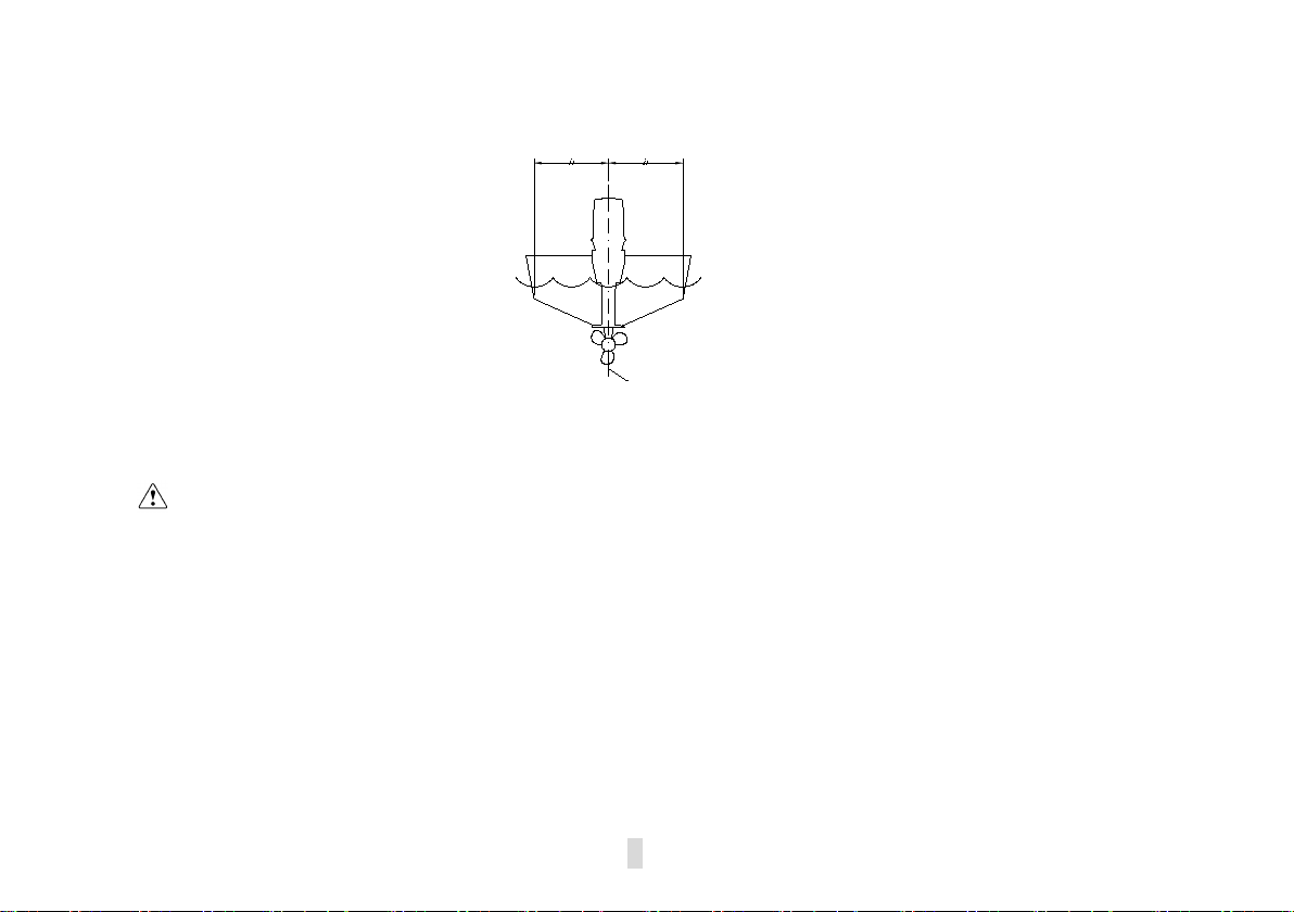
2.1 Installation
Mount the outboard motor on t he cent er l ine (keel line) of the boat. For boat s without a keel or which
are asymmetrical, consult your dealers.
1. Center line (keel line)
NOTE :
During water testing check the buoyancy of the boat, at rest, with its maximum load. Check that
the static water level on the exhaust housing is l ow enough to prevent w a t e r entry into the power
head, when water rises due to waves when the outboard is not running.
WARNING:
Overpowering a boat could cause severe instabilit y. Do not install an out boa rd motor with
more horsepower than the maximum rating on t he cap acit y plate of t he boat. If the boat does
not have a capacit y plate, consult the boat manufacturer.
Improper mounting of t he out board motor could result in hazardous con di tions. Your dealer
or other person e x perienced in proper r igging should mount the motor. Ifyou are mounting
the motor y our se l f , you should be trained by an experienced person.
The information present ed in this section is int ended as reference o nly . Proper mounting
depends in part on experience and the specific boat and motor combination.
2.1.1 Mounting height
The mounting height of th e out board motor greatly affects your boat running efficiency. If the mounting
5

(0-1in)
0~25mm
height is too high, cavitation tends to occur, thus reducing the propulsion. If the m ounting height is too low,
the water resistance w i ll increase and thereby reduce engine e fficiency. Mount the outboard motor so that
the anti-cavitation p late is between the bottom of the boat and a lev el 25 m m b elow it.
motorcombinat ion and the desired us e. Test runs at a di f fer ent height can help determine
theoptimum mou nti ng hei ght. For further information, consult your “PARSUN” dealer or boat
manufacturer.
secure the outb oard to the Tr ansom. Proper installation of the o utboard includes bolt ing the
engine to the bo at through the transom.
NOTE:
The optimum mountin g hei g ht of the outboard motor is af fected by the boat and
2.1.2 Clamping the outboard motor
1. Tighten the t r ansom clamp screw evenly and securely. O cc asionally check the clamp screws for
tightness during operati on of the outboard motor because they could become loose due to engine
vibration.
CAUTION:
Outboards that use clamp bracket screws alone are INS U FFICIENT to properly and safely
6

WARNING:
Loose clamp screws could allow the outboard motor to fall off or move on the transom. This
could cause loss of control. Make sur e the clam p scre ws are tighte ne d secur ely,occasionally check
the screws for tightness during operation.
2. If the engine restraint cable at tachment is equipped
on your engine, an engine r est r aint cable or chain
should be used. Attach to a secure mounting point
on the boat to avoid the engine being completely
lost if it accidentally falls off the transom.
3. Secure the clamp bracket to the transom using the appropriate b olts. For details, consult your
PARSUN dealer.
WARNING:
Avoid using bolts, nut s or washers inappropriate. After tightening, test running the engine
and check their tightness.
2.2 Breaking in engine
Your new engine requires a period of breaking to allow mating surfaces of moving
parts to wear in evenly.
CAUTION
Failure to follow the break -in procedure could result in reduced eng ine life or even severe engine
Damage.
1. For the first hour of operation:
Run the engine at 2000 r/m in or at appr oximately half throttle.
7

2. For the second hour of oper at ion:
·
·
·
·
Run the engine at3000 r/min or at approximately three-quarter thr ot t le.
3. For the next eight hours of operat io n:
Avoid continuous operat i on at full throttle for more than five minutes at a time.
4. Operate the engine normally.
2.3 Pre-operation checks
Fuel
·Check to be sure you have plenty of fuel for your trip.
·Make sure there are no fuel leaks or gasoline fumes.
·Check fuel line connecti ons t o be s ure they are tight
·Be sure the fuel tan k is positioned on a secure, flat surface, and that the fuel line is not twisted
or flattened, or likely to contact sharp objects.
Controls
·Check throttle, shift and steering for proper operation before starting the engine.
·The controls should work smoothly, without binding or unusual fr ee play.
·Look for loose or damaged co nnections.
·Check operation of the starter and stop switches when the outboard motor is in the water.
CAUTION
Do not start t he engine out of water. Overheating and serious engine damage can occur.
Check the engine and engine mounting.
Look for loose or damage d fast eners.
Check the propeller for dam age.
8
Checking the engine oil l evel
1
2
1. Put the outboard motor in an upr ight position (not tilted).
2. Check the oil level using the di pstick to be sure the level falls betw een the upper and lower marks.
Fill with oil if it is below the lower mark, or drain to the specified level if it is above the upper mark.
3
1. Oil dipstick 3. Lower level mark
2. Upper level mark
CAUTION
Be sure to completely insert the dipstick into the dipstick guide.
9
2.4 Filling fuel
WARNING:
Gasoline and it s vapors are highly flammable and explosive. Keep away from sparks, cigarettes,
flames, or other sources of ignition.
1. Remove the fuel tank cap.
2. Carefully fill the fuel tank.
3. Securely close the cap af t er filling the tank. Wipe up any spilled fuel.
2.5 Starting engine
For F25/20BM
1. Connect fuel joints se curely after loosing the air v ent screw on the fuel tank cap (2 or 3 turns).
10
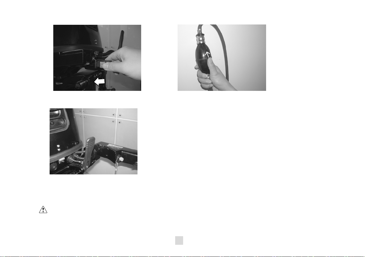
2. Connect fuel joints securely and squeeze the primer pu mp wit h t he outlet end up until you feel
·
·
it become firm (if equipped the fuel joint).
3. Place the gear shift lever in neutral.
NOTE:
The start-in-gear protection device prevent s t he engine from starting except whe n in neutral.
Attach t he engine stop switch lanyard to secure place on your clothing, or your arm or leg. Then
install t he lock plate on the other end of the lanyard into the engine stopswitch.
WARNING:
The engine must be starting in neutral otherwise damage s tarter and hazard can occur.
Do not attach the lanyard to clothing that could tear loose. Do not route the lanyard where it
11

could become entangled and pre venting it from functi oning
·
Avoid accident a lly pull ing the l any ard duri ng normal opera tion. Loss of engi ne p ower me ans
the loss of steeri ng control. Also, without engine power, t he boat could slow rapidly. This
could cause peo ple and objects in the boat to be thrown f orward.
4. Place the throttle grip in t he “START” (start) position.
5. Pull the manual starter handle sl owly until you
feel resistance. Then give a strong pull straight
to crank and start the engi ne. Repeat if necessary.
12
 Loading...