

Parsun F15/F9.9BM, F15/F9.9W Service Manual

PARSUN OUTBOARD ENGINE
SERVICE MANUAL
F15/F9.9BM(F15/F9.9W)
SUZHOU PARSUN POWER MACHINE CO., LTD.

NOTICE
This manual includes service instructions for F9.9, F15 and has been prepared by Parsun Power
primarily for use by the dealers when performing maintenance and repair to Parsun outboard engines.
Before performing maintenance, please read the manual carefully. When performing maintenance and
repair to Parsun outboard engines, please use the service procedure and tools recommended by the
manual. If you use other service procedure and tools, please follow guidance from experienced
maintenance people, to avoid damage to people and outboard engines.
The manual is based on the sample machines that are produced at the time of printing, so the model
being actual purchased may differ a little from the descriptions and illustrations given in this manual.
If necessary, our company will distribute the manual revision to dealers.
In this Service Manual, particularly important information is distinguished in the following ways,
please ready the manual carefully, and perform the instructions correctly and carefully.
WARNING:
Failure to follow WARNING instructions could result in severe injury or death to the machine operator
and bystander.
CAUTION:
A CAUTION indicates special precautions that must be taken to avoid damage to the outboard motor.
NOTE:
A NOTE provides key information to make procedures easier or clearer.
The common troubles and solutions are given in the end of the manual, please ready carefully. When
performing maintenance and repair to Parsun outboard engines, they will help you judge the outboard
engine’s status quickly and improve the work efficiency.
All rights reserved.
This manual cannot be reproduced or transmitted in any
form or by any means without the written approval of our
company.
Suzhou Parsun Power Machine Co., Ltd.

INDEX
GENERAL INFORMATION················································································································1
IDENTIFICATION···································
···············································································1
PROPELLER SELECTION···································································································1
EMERGENCY ST AR T···································
·········································································1
SAFETY WHILE WORKING································································································2
DISASSEMBL Y AND ASSEMBL Y···················································
·····································3
ONE-TIME USE P ARTS··················································
·······················································4
PRE-DELIVERY CHECK······································································································4
SPECIAL T OOLS AND DETECTION DEVICE·································································
6
EXPLOSIVE DRA WING AND SYMBOL·············································································8
SPECIFICATIONS··············································
··················································································9
OUTBOARD ENGINE SPECIFICA TIONS·········································································9
MAINTENANCE INFORMA TION·····················································································10
Power unit··························································
······························································10
Lower unit························································································································11
Ignition system·············································
····································································11
Charge system······························
····················································································12
TIGHTENING TORQUE······································································································12
Specified torque··················································
·····························································12
General torque·················································································································13
PERIODIC SERVICE·······························································
··························································14
MAINTENANCE TIME T ABLE····································
······················································14
FUEL SYSTEM··················································
····································································15
POWER UNIT······································
··················································································15
Engine oil level·················································································································15
Changing engine oil·····················································
····················································16
V alve clearance················································································································16
Spark plug·········································
···············································································17
CONTROL SYSTEM············································································································17
Throttle grip····························
·························································································17
Idling speed····················································
··································································18
Start-in-gear protection···································································································19
LOWER UNIT···························
·····························································································19
Gear oil··················································
···········································································19
Changing gear oil·············································································································19
Lower unit leakage check·····················································································
··········20
GENERAL INSPECTION·······················
··············································································20

Anode································································································································20
Grease points······················
······························································································20
Cooling water passage·····································································································21
Thermostat·····························
··························································································22
RECOIL STARTER·····························································································································22
NOTICE··································································································································22
EXPLOSIVE DRAWING··················································
····················································23
DISASSEMBLING·················································································································27
ST ART ROPE REPLACEMENT··························································
·······························27
DISASSEMBLING AND INSPECTION··············································································28
ASSEMBLING················································
·······································································29
INSTALLATION····················································································································29
IGNITION SYSTEM······················································
·····································································29
NOTICE··································································································································29
EXPLOSIVE DRA WING··················································
····················································30
WIRING DIAGRAM·············································································································35
SP ARK PLUG IGNITION···························
··········································································35
SP ARK PLUG CAP··································
··············································································36
FL YWHEEL MAINTENANCE····························································································36
CDI INSPECTION·································
················································································36
IGNITION COIL INSPECTION ············································
··············································36
PULSED COIL INSPECTION ·····························································································37
CHARGE COIL INSPECTION ··································
··························································37
FUEL SYSTEM··················································
··················································································38
NOTICE··································································································································38
EXPLOSIVE DRA WING··················································
····················································38
THROTTLE CONNECTING ROD ADJUSTMENT·························································44
FUEL JOINT REMOVAL AND INSPECTION··································································44
FUEL PUMP REMOVAL AND INSPECTION···································································
44
FIL TER INSPECTION··········································································································45
POWER UNIT······································
································································································46
NOTICE··································································································································46
EXPLOSIVE DRA WING··················································
····················································46
SPECIAL T OOLS··················································································································54
COMPRESSION PRESSURE INSPECTION····································································
54
OIL PRESSURE INSPECTION···························································································55
OIL PRESSURE SWITCH INSPECTION·····················································
·····················55

DISASSEMBLING POWER UNIT······················································································55
BEL T PULLEY AND TIMING BELT····························································
······················56
DISASSEMBLING AND INSPECTION··············································································57
CYLINDER COVER·························································
·············································57
Disassembling············································································································57
V alve and valve guide bush······························································
························58
V alve spring··························
·····················································································58
V alve r ocker arm and rocker shaft·········································································
58
Camshaft···················································································································58
Oil pump check··············································
···························································59
V alve guide bush replacement·················································································59
V alve seat inspection·······························
··································································60
V alve seat cutting······································································································61
V alve installation·············
··························································································61
Assembling cylinder cover·······················································································61
CRANKCASE··················································································································61
Disassembling············································································································61
Piston··············································
···········································································62
Cylinder bore·······················································
·····················································62
Piston pin diameter························
···········································································63
Piston ring·················································································································63
Crankshaft·················································································································63
Crankpin oil clearance·····························································································63
Main journal oil clearance ····················································
···································64
Cylinder body and crankcase·······························································
···················64
FULL INSTALLATION··································································································64
Piston connecting rod installation·······················································
····················64
Piston ring installation·····························································································65
Piston installation··················································
···················································65
Crankshaft installation····························································································65
Assembling power unit·········································
····················································66
UPPER UNIT········································································
································································68
TOP COWLING··········································································
···········································68
Explosive drawing·····························································································
··············68
Disassembling and inspection·························································································69
BOTTOM COWLING·····································
······································································70
Explosive drawing···············································
····························································70
Disassembling and inspection·························································································74
STEERING HANDLE···········································································································75
Explosive drawing··························································································
·················75

Disassembling and inspection·························································································78
BRACKET······························································································································
79
Explosive drawing···········································································································79
Disassembling and inspection··························
·······························································83
UPPER UNIT························································
··································································85
Explosive drawing···········································································································85
Disassembling and inspection···························
······························································86
LOWER UNIT········································································
······························································87
W ATER PUMP ASSEMBLY·····································
····························································87
Explosive drawing···········································································································87
Disassembling and inspection·····················
····································································88
LOWER UNIT·····················
···································································································89
Explosive Drawing···········································································································89
Disassembling and inspection····················
·····································································94
Propeller shaft and clutch block····
··········································································94
Dog clutch installation······························································································95
Lower casing cover···································································································95
Lower casing cover oil seal and bearing installation·············································
95
Drive shaft·················································
································································96
Shift rod cam·············································································································96
Gear···························································································································96
Forward gear bearing······························································································96
Lower casing inspection·······································
····················································96
Assembling lower casing·········································
·················································96
Lower unit installation·····························································································97
Shim selection····················
························································································98
COMMON TROUBLES AND SOLUTIONS······························
······················································99
GENERAL INFORMATION
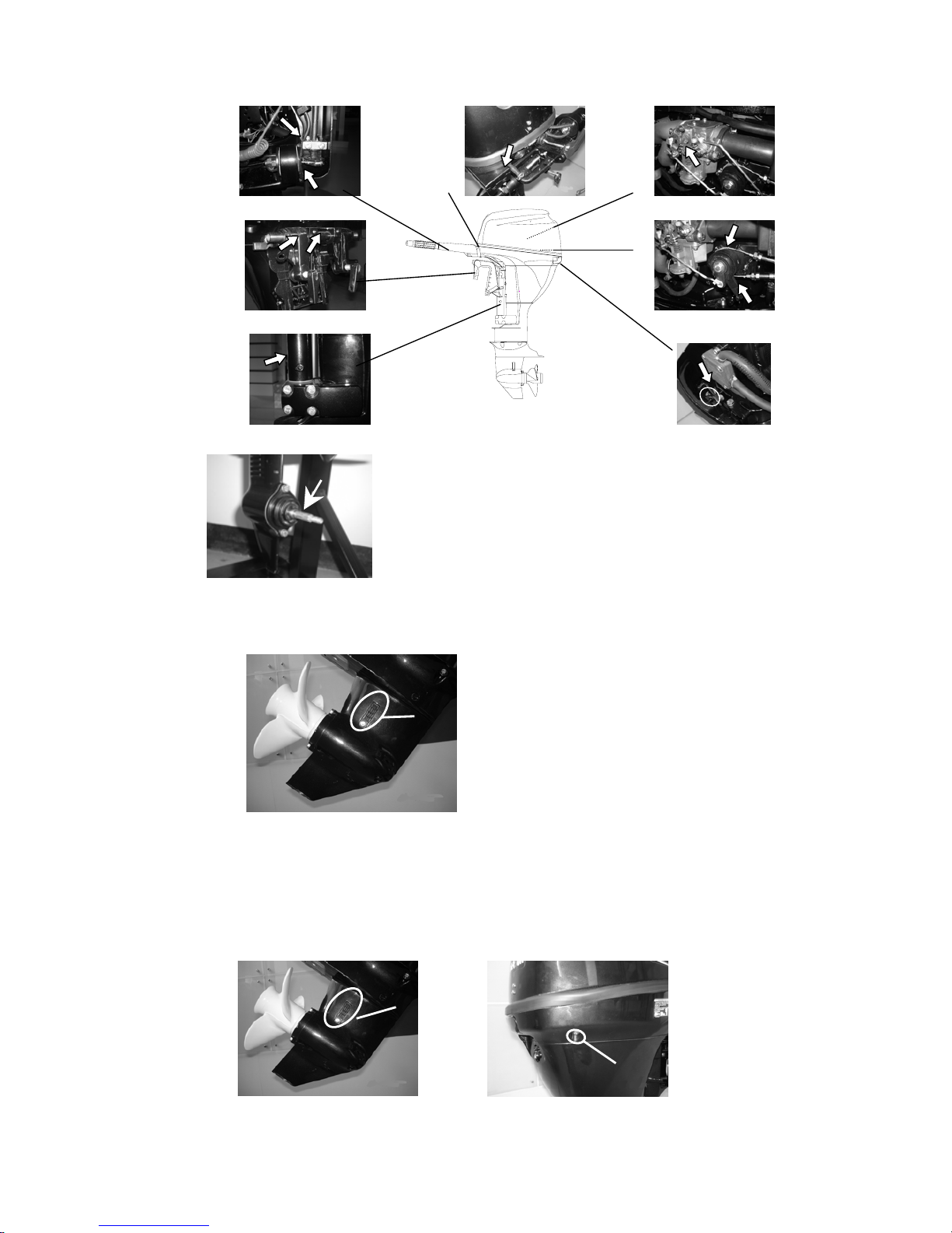
IDENTIFICATION
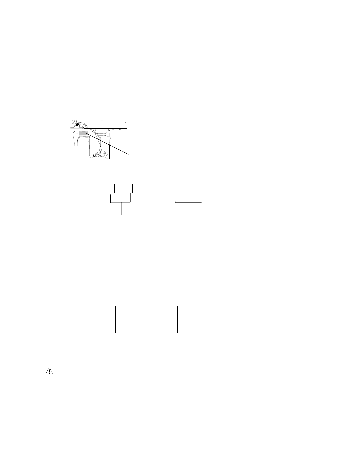
The outboard motor serial number is marked on the label. The label can be found on the bracket left
assembly or on the upper part of the bracket swivel. Record your outboard motor serial number in the
spaces provided to assist you in ordering spare parts from your Parsun dealer or for reference in case
your outboard motor is stolen.
1
1. Outboard motor serial number location
Serial number as follows:
SN
MOTOR BATCH SEQUENCE NUMBER
PRODUCTION CODE
PROPELLER SELECTION
The performance of your outboard motor will be critically affected by your choice of propeller, as an
incorrect choice could adversely affect performance.
For a greater boat load and a low engine speed, a smaller-pitch propeller is more suitable. Conversely,
a large-pitch propeller is more suitable for a smaller operating load as it enables the correct engine speed
to be maintained.
When the engine is running at full throttle position, the suitable propeller should be used according to
the engine’s RPM and the fuel capability. So the outboard engine can supply the best performance.
Propeller sizes Material
9 1/4×8
9 1/4×11
Aluminum alloy
EMERGENCY START
If the starting device is not working, the engine can be started by emergency start cable.
WARNING:
The start program can only be used in emergency and to return to harbor for repairing.
When you start the engine by emergency start cable, the start-in-gear protection device is not
working. So please ensure the shift rod is in NEUTRAL position.
Please ensure nobody standing behind you in case the cable is pulled out to hurt people.
After the engine starts up, don’t fit the start device or top cowling. Put clothing or other
1
items far away. Don’t touch flywheel or other moving parts.
When starting and operating, don’t touch ignition coil, spark plug cap or other electric parts.
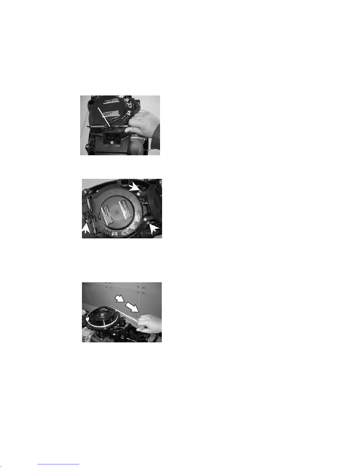
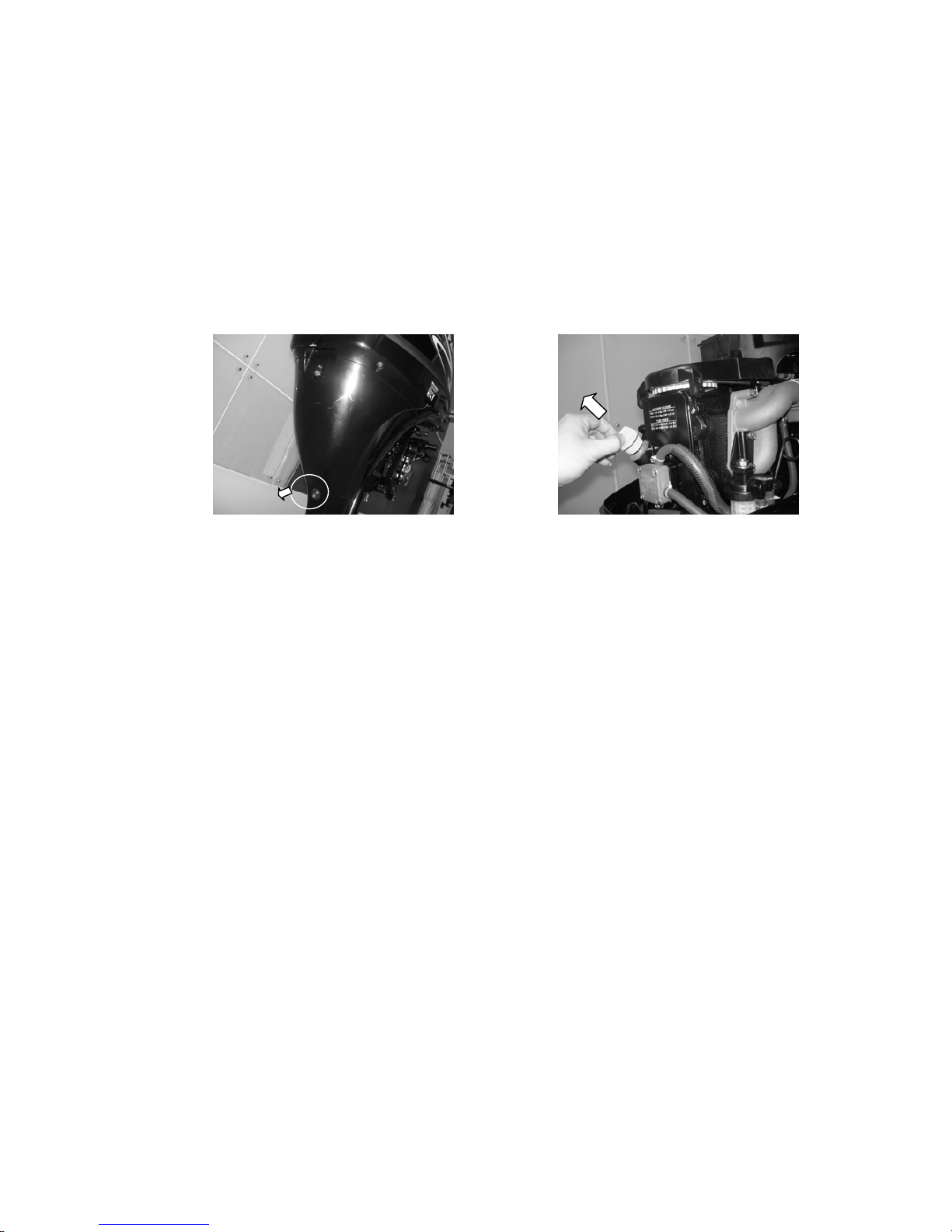
The procedure is as follows:
1. Remove the top cowling.
2. Remove the start-in-gear protection device cable.
1. Start-in-gear protection device cable
3. Demount three bolts and remove starter.
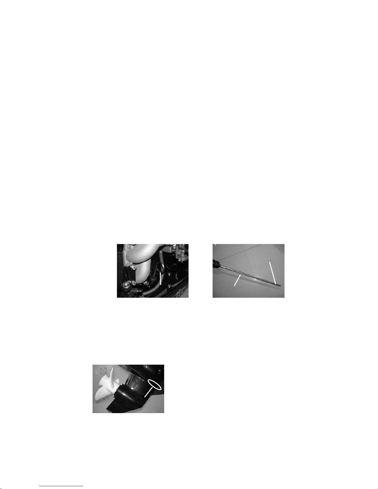
4. Insert the knot of the cable in the notch of flywheel rotor, and wind the cable around flywheel
several rounds in clockwise direction..
5. Pull the manual starter handle slowly until you feel resistance.
6. Give a strong pull to start the engine. Repeat if necessary.
SAFETY WHILE WORKING
To prevent the danger or accidents when performing maintenance and repair, and improve the work
efficiency, please obey the following safety procedures.
1. FIRE PREVENTION
Gasoline (petrol), lubricant and grease are highly flammable. While working, keep away from heat,
sparks and open flames.
2

2. VENTILATION
Petroleum vapor and engine exhaust gases are violent in toxicity. They are harmful to breathe and
deadly if inhaled in large quantities. When test-running an engine indoors, maintain good
ventilation.
3. SELF-PROTECTION
Protect your eyes with suitable safety glasses or safety goggles, when drilling, grinding or
operating air compressor. Protect hands and feet by wearing protective work clothes, safety
gloves and shoes if necessary.
4. LUBRICANTS AND SEALING FLUIDS
When performing maintenance procedures and repair to Parsun outboards, use only products
provided or recommended by our Company.
Under normal conditions of use, there should be no hazards from the use of the lubricants
mentioned in this manual, but safety is all-important, and by adopting good safety practices, any
risk is minimized.
○
1 To protect the skin, the application of a suitable barrier cream to the hands before working is
recommended.
○
2 Clothing which has become contaminated with lubricants should be changed as soon as
practicable, and washed before further use.
○
3 Avoid skin contact with lubricants.
○
4 Hands and any other part of the body which have been in contact with lubricants or
lubricant-contaminated clothing, should be thoroughly washed with hot water and soap as
soon as practicable.
○
5 A supply of clean lint-free cloths should be available for wiping run-off lubricants or grease.
5. GOOD WORKING PRACTICES
○
1 Follow the tightening torque instruction. When tightening bolts, nuts and screws, tighten
the large sizes first, and tighten inner-positioned fixings before outer-positioned ones.
○
2 Use the recommended special tools to protect parts from damage. Use the right tool in the
right manner.
DISASSEMBL Y AND ASSEMBLY
When disassembly and assembly, please follow the following principles:
1. Use special tools when disassembling and assembling.
2. Clean dirt before disassembling the parts.
3. Oil the contact surfaces of moving parts before assembly.
4. Install bearing with the manufacturer’s markings on the side exposed to view and liberally oil the
bearing.
3
5. When installing oil seals, apply a light coating of water-resistant grease to the ledge and outside
diameter.
6. After assembly, check if the moving parts operate normally.
ONE-TIME USE PARTS
One-time use parts are gasket, oil seal, O-ring, cotter pin and spring, ring, and etc.. When
re-assembling outboard engine, you must change the one-time use parts.
PRE-DELIVERY CHECK
To ensure the using, please inspect the following before delivery.
1. CHECKING FUEL SYSTEM
Check if the fuel pipe is connected firmly, and if the fuel tank is filled with fuel.
CAUTION:
Do not use pre-mixed fuel for this 4-stoke outboard engine.
2. CHECKING OIL LEVEL
○
1 Check the engine oil level
Remove oil cap, check engine oil level..
3
2
1
1. Oil cap 2. High position mark 3. Low position mark
Ensure the oil level between the marks of upper and lower. If above upper level, drain engine
oil; if below lower mark, add engine oil up to upper level.
○2 Check the gear oil level
Remove the oil level plug. Check if the gear oil overflows at the oil level checking hole. If
so, install the oil level plug and tighten it according to specified torque. Otherwise please add
gear oil.
1
1. Oil level plug
4

3. CHECK STEERING SYSTEM
Check if steering is stable.
Check if steering friction is adjusted correctly.
Turn clamp handle screw clockwise to increase
resistance.
Turn clamp handle screw counter clockwise to lower
1
resistance. 1. Clamp handle screw
4. CHECK SHIFT LEVER AND THROTTLE
Check if the shift lever is operated smoothly.
Check if the throttle grip is turned smoothly from full closed position to full open position.
5. CHECK ENGINE STOP SWITCH ASSY
Check if the engine stops when pushing the engine stop switch assembly or pulling out the stopper
hang rope.
6. CHECK COOLING WATER CHECKING HOLE.
When the engine is running, check if cooling water overflows at the cooling water checking hole.
1. Cooling water checking hole
7. BREAKING-IN RUNNING
○1 Initial 1 hour: operate the engine at 2000 r/min or about a half throttle.
② The second hour: operate the engine at 3000 r/min or about 3/4 throttle.
③ The following 8 hours: operate the engine at full throttle continuously. Each operation time
doesn’t exceed 5 minutes.
8. INSPECTION AFTER BREAKING-IN RUNNING
○1 Check if gear oil contains water..
② Check if the fuel line leaks.
③ After breaking-in running, operate the engine at idling speed. Use cleaning tool to wash over
the cooling water passage by fresh water.
9. AFTER BREAKING-IN RUNNING, INSPECT IDLING SPEED.
① Preheating engine for 5 minutes.
② Using the tachometer to measure idling speed RPM.
If out of specification, adjust it. Idling speed: 900~1000 r/min.
③ Turn the throttle stop screw clockwise or counter clockwise
until the specified idling speed is attained.
④ After adjusting idling speed, picking up RPM several times to check the engine’s stability.
1
5
SPECIAL TOOLS AND DETECTION DEVICE
When performing maintenance and repair, you need to use all kinds of special tools and detection device.
The use of correct tools will improve the work efficiency and avoid of the damage to the people and
outboard engines.
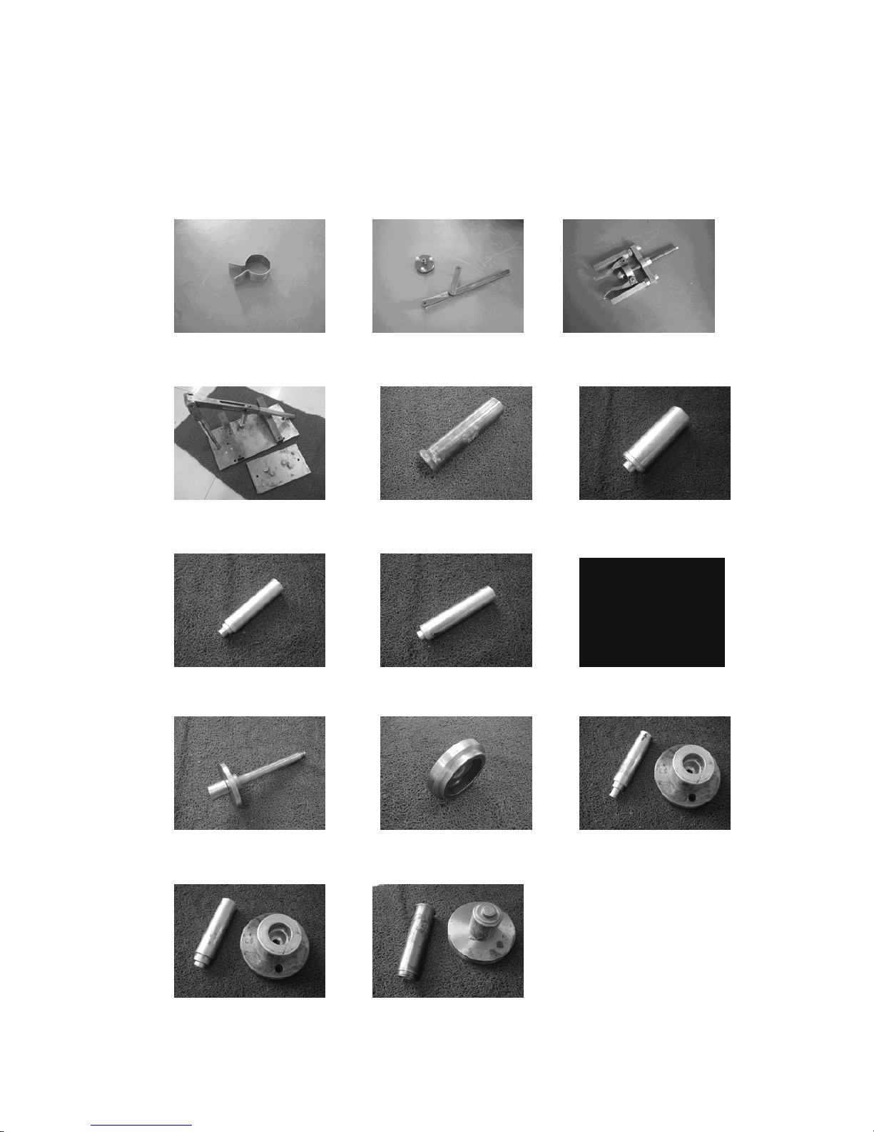
SPECIAL T OOLS:
Piston slider Flywheel gripper and puller Bearing puller
Valve spring compressor Housing oil seal installer Lower casing cover bearing installer
Lower casing cover barrel bearing installer, Lower casing cover oil seal installer Space gage
Needle bearing installer Oil cleaner spanner Bearing block copper sleeve installer
Bearing block oil seal installer Forward gear bearing installer
6

DETECTION DEVICE:
Digital tachometer Digital circuit tester Peak voltage adaptor
7
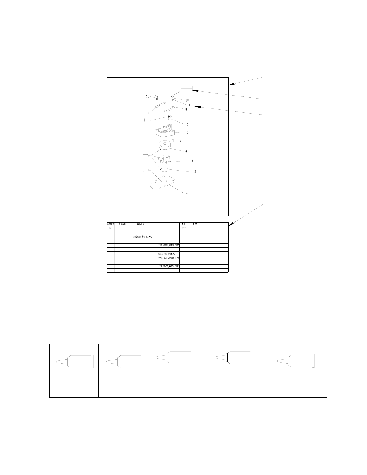
EXPLOSIVE DRAWING AND SYMBOL
EXPLOSIVE DRAWING
1
2
3
4
5
6
7
8
9
10
G
G
DESCRIPTION
PART NO.
REMARKS
F15-06060002
F15-00000013
F15-06060001
F15-06060004
F15-06000014
F15-06050000
F15-06000007
六角螺栓 M8X45
泵壳固定板
泵壳水管密封圈
水泵壳体
定位销φ4X12
水泵内壳
水泵叶轮组件
外挡板
OUTER PLATE
O-RING
IMPELLER
PIN,DOWEL
SEAL
BOLT,HEXAGON
4
2
1
1
2
1
1
1
1
GB/T5783-2000
JASO F404-96
M8x45 mm
18 Nm
L
1277
G
F15-02000004
水管密封圈上
1
③
②
①
④
① Parts explosive drawing.
② Screw specification and specified torque.
③ Oil, fluid sealant or locking substance daubing point.
④ Spare parts details.
SYMBOL
O
G
L
1277
L
1243
GM
Daub engine oil
Daub waterproof
grease
Daub screw locking
substance 1277
Daub screw locking
substance 1243
Daub fluid sealant
8

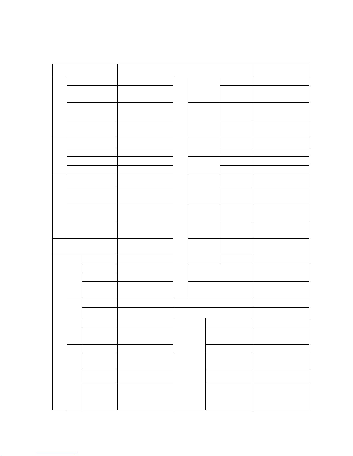
SPECIFICATIONS
OUTBOARD ENGINE SPECIFICATIONS
Item Description Item Description
Overall length 1001mm
Ignition
system
C.D.I
Overall width 427mm
Starting
enrichment
Choke valve
S 1080mm Spark plug DPR7HS
Dimension
Overall
height
L 1207mm
Exhaust
system
Under water
S 49kg
Power Unit
Lubrication
system
Pressure lubrication
Weight
L 51kg Fuel type
Unleaded regular
gasoline
7.3Kw(9.9hp)@5000r/min
9.9Kw(13.5hp)@5000r/min
Max output
11Kw(15hp) @5000r/min
Fuel standard
Fuel tank
capacity
PON86、RON91
Full throttle
operation
4500~5500 r/min
Recommended
engine oil
API SE, SF, SG, SH,
SJ SAE 10W30,
10W40
3.5L/h@5500 r/min(7.3Kw)
Max fuel
consumption
5.3L/h@5500 r/min(11Kw)
Engine oil
quantity
1.2L
Performance
Idle speed
(Neutral)
950±50 r/min
Recommended
gear oil
Hypoid gear oil SAE
﹟90
Type 4 stroke, OHV
Fuel and Oil
Gear oil
quantity
250 cm³
Number of
cylinders
2 Tilt angle 8
o
,12 o,16 o, 20
o
Displacement 323cm³ Tilt-up angle 63
o
Bore×Stroke 59mm×59mm
Bracket
Steering angle 45 o +40
o
Compression
ratio
9.19:1 Gear positions F-N-R
Min. compression
pressure
765kPa Gear ratio 2.08
Number of
carburetors
1 Gear type Spiral bevel gear
Control system Tiller control Clutch type Dog clutch
Power Unit
Starting system Recoil starter
Drive Unit
Propeller drive
system
Spline
9
MAINTENANCE INFORMATION
Power unit
Item Description Item Description
Warp limit 0.1mm Intake
0.15~0.25mm
Camshaft inside
diameter
35.000~35.012mm
Valve
clearance
(cold)
Exhaust
0.20~0.30mm
Rocker shaft
outside diameter
12.941~12.951mm Intake
1.98~3.11mm
Cylinder Head
Rocker inside
diameter
13.000~13.018mm
Face width
Exhaust 1.98~3.11mm
Bore 59.00~59.015mm Intake
0.6~0.8mm
Wear limit 59.1mm
Seat width
Exhaust 0.6~0.8mm
Taper limit 0.08mm Intake
0.50~0.90mm
Cylinder
Out of round limit 0.05mm
Margin
thickness
Exhaust 0.50~0.90mm
Piston diameter 58.950~58.965mm Intake
27.9~28.1mm
Measuring point
height
5mm (from the
bottom of piston)
Head
diameter
Exhaust 21.9~22.1mm
Piston-to-cylinder
clearance
0.035~0.065mm Intake
5.475~5.490mm
Piston
Pin boss inside
diameter
14.004~14.015mm
Stem
outside
diameter
Exhaust 5.460~5.475mm
Piston pin outside
diameter
13.996~14.000mm Intake
Thickness
1.17~1.19mm
Guide
inside
diameter
Exhaust
5.500~5.512mm
Breadth 2.0~2.20mm
End gap 0.15~0.30mm
Stem to guide clearance 0.025~0.052mm
Top ring
Side
clearance
0.04~0.08mm
Valve
Stem roundness limit 0.01mm
Thickness
1.47~1.49mm Rocker shaft outside diameter 12.941~12.951mm
Breadth 2.50~2.70mm
Rocker inside diameter 13.000~13.018mm
End gap 0.30~0.50mm
Free length 34.40mm
2nd ring
Side
clearance
0.02~0.04mm
Free length limit 32.68mm
Thickness
2.31~2.51mm
Valve
spring
Tilt limit 1.5mm
Breadth 2.30~2.60mm
Small end inside
diameter.
14.015~14.029mm
End gap 0.20~0.70mm
Big end inside
diameter.
31.031~31.042 mm
Piston ring
Oil ring
Side
clearance
0~0.22mm
Connecting rod
Big end oil
clearance
0.021~0.045mm
10

Intake
27.596~27.696mm Journal diameter 34.997~35.009 mm
Height
Exhaust
27.616~27.716mm
Crankpin
diameter
30.997~31.009 mm
Round diameter 23.950~24.050mm Crankpin width 21.00~21.07mm
Journal diameter 34.935~34.955mm
Big end side
clearance
0.05~0.22mm
Camshaft
Camshaft round
limit
0.03mm
Crankshaft
Round limit 0.05mm
Discharge 5.70L/min
Opening
temperature
58~62ºC
Safety valve
opening pressure
388.0~450.0kPa
Full-opening
temperature
70ºC
Outside rotor to
housing clearance
0.100~0.150mm
Thermostat
Valve lift height 3mm
Outside rotor to
inside rotor
clearance
0.040~0.140mm
Oil pump
Rotor to cover
clearance
0.030~0.090mm
Lower unit
Item Description Item Description
Drive gear to forwarder
gear
0.19~0.86mm
Forwarder
gear shim
0.10, 0.12, 0.15, 0.18, 0.30, 0.40,
0.50mm
Drive gear to back gear 0.95~1.65mm
Back gear
shim
0.10, 0.20, 0.30, 0.40, 0.50mm
Gear
Clearance
Drive gear shim 1.13, 1.22mm
Gear
Clearance
Ignition system
Item Description Item Description
Ignition timing BTDC 30º Pulsed coil resistance 234~348Ω
Spark plug gap 0.8~0.9mm Primary coil 0.16~0.25Ω
Start (load) 155V
Ignition
assembly
resistance
Secondary coil 3.92~6.65KΩ
1500r/min 170 V Start (no-load) 175V
CDI output
peak voltage
3500r/min 170 V Start (load) 170V
Start (no-load) 4.0 V 1500rmp 180V
Start (load) 4.0 V
Charge coil
peak voltage
3500rmp 180V
1500r/min (load) 9 V Charge coil resistance 272~408Ω
Pulsed coil
peak voltage
3500r/min (load) 17V
11

Charge system
Item Description Item Description
Min. (3000 r/min) 5.5 A Start (load) 14 V
Charge
current
Max. (5000 r/min) 6.0 A 1500r/min (no-load) 30 V
3000r/min (no-load) 24 V
Light coil
output
3500r/min (no-load) 70 V
Rectifie
r
peak
voltage
5000r/min (no-load) 38 V Light coil resistance 0.33~0.72Ω
TIGHTENING T ORQUE
Specified torque
Part to be tightened Part name
Thread
size
Quantity Torque
Safety valve — — 1 8Nm
Spark plug — M12 1 18 Nm
Recoil starter Bolt M6 3 8 Nm
Flywheel Nut M16 1 110 Nm
Carburetor
Bolt
M6 2 10 Nm
Intake manifold
Bolt
M6 4 8 Nm
Cylinder head cover
Bolt
M6 4 8 Nm
1st tightening
15 Nm
2nd tightening
Bolt M8 4
30 Nm
1st tightening 6 Nm
Cylinder
head
2nd tightening
Bolt M6 3
12 Nm
Oil filter — — 1 18 Nm
Oil filter stud — — 1 40 Nm
Locknut (rocker arm) Nut M6x0.75 4 14 Nm
Oil pump Bolt M6 2 8 Nm
Power unit assembling Bolt M8 6 21 Nm
1st tightening
6 Nm
Exhaust
cover
2nd tightening
Bolt M6 7
12 Nm
Breather cover Bolt M6 3 8 Nm
1st tightening
15 Nm
2nd tightening
Bolt M8 4
30 Nm
1st tightening
6 Nm
Crankcase
2nd tightening
Bolt M6 6
12 Nm
1st tightening
10 Nm
Connecting
rod
2nd tightening
Bolt M7 2
21Nm
Oil pressure switch — — 1 18 Nm
Driven belt pulley Bolt M6 1 13 Nm
Power unit
Timing pulley Nut M28 1 54 Nm
12
Lower unit mounting Bolt M8 4 18 Nm
Lower unit housing cover Bolt M6 2 8Nm
Anode Bolt M6 1 8 Nm
Water pump housing Bolt M8 4 18 Nm
Water pump base Bolt M8 2 18 Nm
Water inlet Bolt M5 2 5 Nm
Oil drain bolt Bolt M8 1 9 Nm
Oil filler hole Bolt M8 2 9 Nm
Pinion Nut M8 1 25 Nm
Lower unit
Propeller nut Nut M10 1 17 Nm
Steering handle mounting Bolt M8 1 18 Nm
Shift lever bracket Bolt M6 1 4.5 Nm
Clamp bracket Nut M8 1 13 Nm
Upper
Unit
Oil drain bolt Bolt M14 1 27 Nm
Ignition assy Bolt M6 2 8 Nm
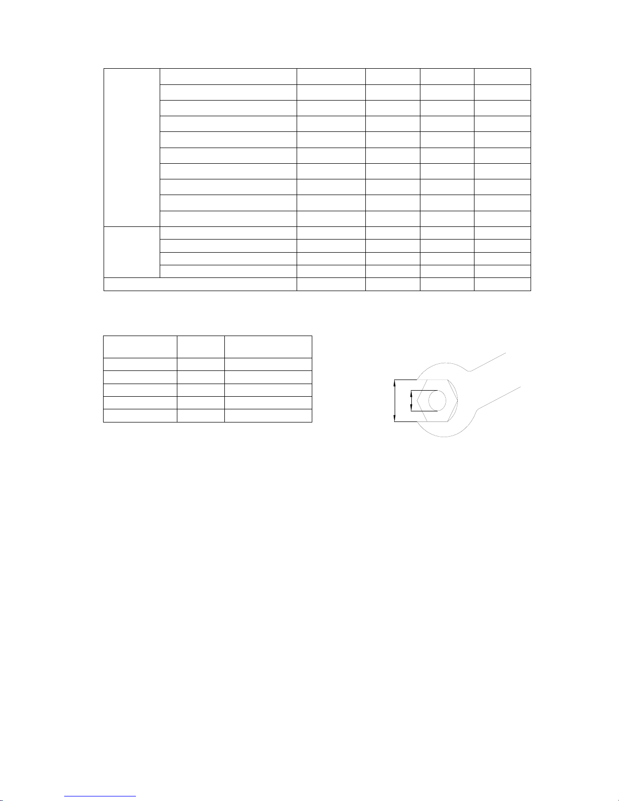
General torque
Nut (a) Bolt (b) Torque
8mm M5 5Nm
10mm M6 8 Nm
12mm M8 18 Nm
14mm M10 36 Nm
17mm M12 43 Nm
b
a
13

PERIODIC SERVICE
MAINTENANCE TIME TABLE
Initial maintenace General maintenance
period
Items
Contents
10 hours
(month)
50 hours
(3 months)
100 hours
(6 months)
200 hours
(1 year)
Anode
Inspection/ replacement
○ ○
Spark plug
Cleaning/ adjustment
/ replacement
○ ○
Grease points
Greasing
○
Bolts and nuts
Inspection
○ ○
Fuel filter
Inspection/ replacement
○ ○ ○
Fuel tank Inspection/ cleaning ○
Throttle cable
Inspection/ adjustment/
replacement
○ ○
Idling speed
Inspection/ adjustment
○ ○
Start-in-gear
projection
Inspection/ adjustment
○ ○
Engine oil
Replacement
○ ○
Oil filter
Replacement
○
Valve clearance
(OHC)
Inspection/ adjustment
○ ○
Ignition timing
Inspection
○ ○
Thermostat
Inspection
○
Cooling water
passage
Inspection/ Cleaning
○ ○
Gear oil
Replacement
○ ○
Water pump
Inspection
○
Propeller
Inspection/ replacement
○ ○
Timing belt
Inspection/ replacement
○ ○
CAUTION:
After running the outboard engine in salt water, waste water or mud water, wash over
the engine by fresh water immediately.
If using leaded gasoline frequently, check the valve and components each 100 hours.
Timing belt should be changed every 1000 hours (5 years).
14
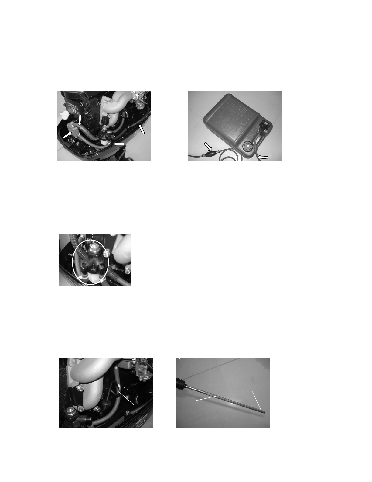
FUEL SYSTEM
1. CHECK FUEL TANK, CARBURETOR, FUEL PUMP AND FUEL PIPE
Check if fuel tank, carburetor, fuel pump and fuel pipe are damaged or leaked.
Replace if necessary.
Check if the fuel filter on the tank is dirty. Clean dirt or replace if necessary.
2. CHECK FUEL COCK AND FUEL JOINT
Check if fuel cock and fuel joint are cracked, damaged or leaking.
Replace if necessary.
3. CHECK FUEL FILTER
Check if fuel filter is cracked, damaged or has dirt inside.
If so, replace.
CAUTION:
Clean the spilled fuel.
POWER UNIT
Engine oil level
1. Remove oil rule, check engine oil level, if between the following marks of the upper and
lower.
3
2
11
1. Oil rule 2. High position mark 3. Low position mark
15
2. If above the upper mark, drain the engine oil; if below lower mark, add engine oil up to upper mark.
CAUTION:
Run the engine and then turn it off, wait for several minutes, and check the engine oil level by the
oil rule again.
If the engine oil still not within the proper level, add/drain as needed.
Changing engine oil
1. Remove oil level plug, drain plug with washer and gasket; drain off the engine oil.
2. Install new bolt and washer; install drain plug.
3. Fill engine oil through oil filler hole.
Engine oil quantity: 1.0 L (Before changing oil filter)
1.2 L (After changing oil filter)
Oil type: API SE, SF, SE-SF, SG-CD SAE 10W30, 10W40
4. Install oil level plug.
5. Check engine oil level.
Valve clearance
1. Remove stopper hang rope from engine stop switch assy.
Remove spark plug cap from spark plug.
2. Remove starter and belt cover.
3. Remove fuel pump and cylinder cover.
4. Rotate the flywheel clockwise to make the mark “1” on driven pulley align with the mark“▼” on
the cylinder head.
Check the clearance between the intake and exhaust valves of the upper cylinder. Adjust it if
necessary.
5. Rotate the flywheel clockwise to make the mark “2” on driven pulley align with the mark“▼” on
the cylinder head.
Check the clearance between the intake and exhaust valves under the lower cylinder. Adjust it if
necessary.
CAUTION:
16
Don’t rotate the flywheel counter clockwise in case the valve system is damaged.
NOTE:
Adjust the valve clearance when the engine is cold.
Intake valve 0.15~0.25mm
Valve clearance
(cold position)
Exhaust valve 0.20~0.30mm
6. Loose lock nut, rotate adjusting bolt to reach the specified valve clearance.
NOTE:
Rotate adjusting bolt clockwise to reduce the valve clearance.
Rotate adjusting bolt counter clockwise to increase the valve clearance.
7. Re-assemble the spare parts.
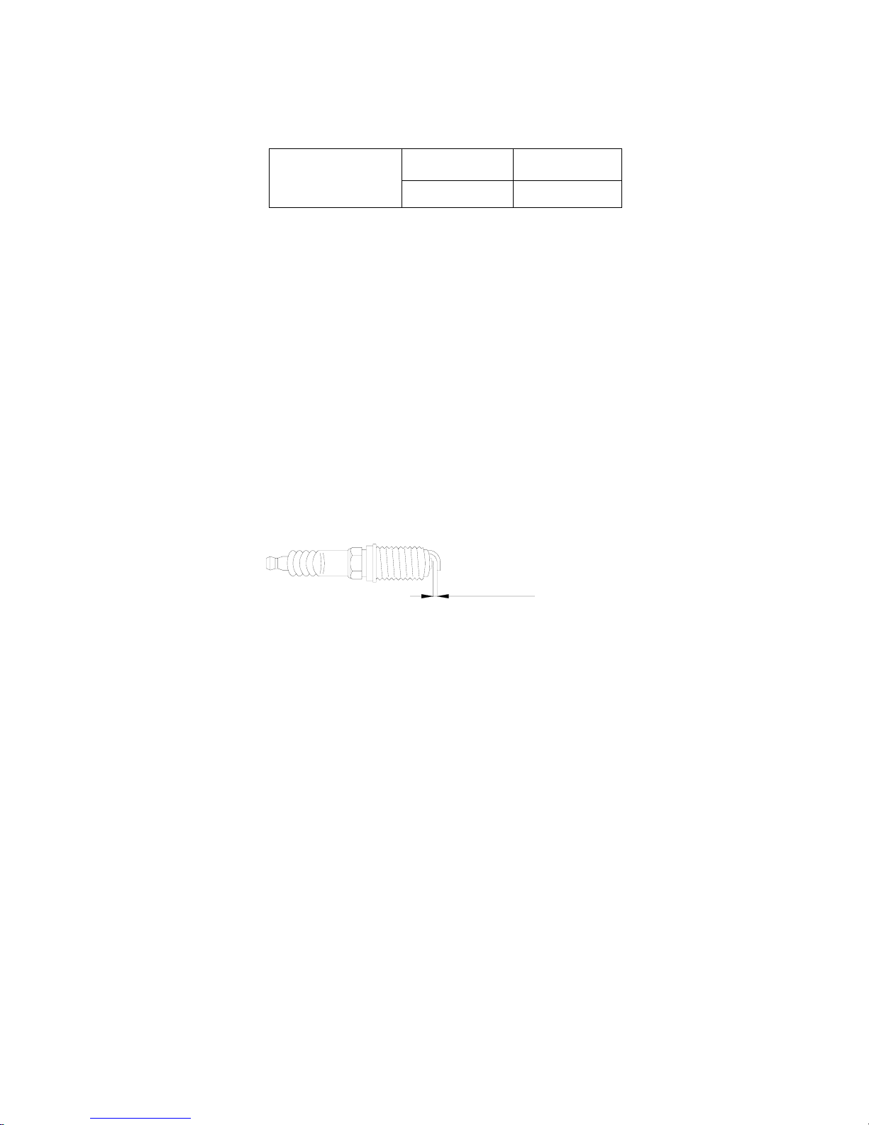
Spark plug
1. Remove spark plug cap and spark plug.
2. Clean off carbon build-up on the electrodes.
3. Check if the electrodes are corroded or have deposit, or if the washer is damaged. If necessary,
change the spark plug.
Spark plug type:DPR7HS
4. Inspect if the spark plug gap is within specification. If necessary, change the spark plug.
0.8-0.9mm
5. Install spark plug. Use spark plug spanner to tighten it according to specified torque.
Specified torque: 18 Nm
CONTROL SYSTEM
Throttle grip
Recoil start type
1. Turn the throttle grip to fully closed position.
2. Check if the throttle cable is slack, if the throttle lever touches the throttle stop screw, or if the
arresting stop on the throttle accelerograph enforce touches the check plate on the fixed mount.
3. Loosen the throttle cable adjusting screw, adjust the throttle cable position, and tighten throttle cable
adjusting screw.
17
1. throttle cable stop screw
1
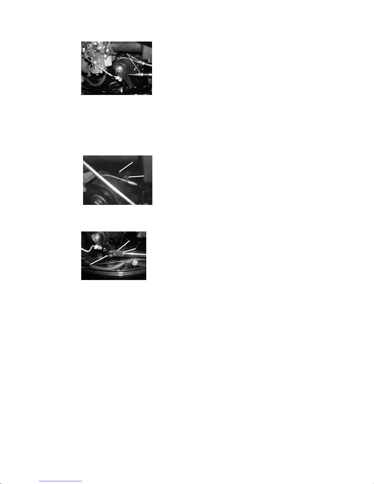
Electric start type
1. Turn the gear shift lever to neutral position.
2. Check if the arresting stop on the throttle accelerograph enforce touches the check plate on the
bracket.
2
1
1. check plate 2. arresting stop
3. Loosen the lock nut and take out the cotter pin, then remove the cable joint.
1. cotter pin 2. cable joint 3. lock nut
213
4. Adjust the joint position to make the joint hole align with the pin on the throttle accelerograph
enforce.
CAUTION:
The cable joint must be screwed in for over 8mm.
5. Fit on the cotter pin and tighten the lock nut.
Idling speed
Check idling speed, and adjust it if necessary.
1. Preheat engine for 5 minutes.
2. Attach the tachometer to the spark plug wire to measure idling speed RPM. If out of
specification, adjust it.
Idling speed: 900~1000 r/min
18
3. Turn the throttle stop screw clockwise or counter clockwise, until the specified idling
speed is attained.
2
1
NOTE
:
Turn clockwise to increase idling speed.
Turn counter clockwise to decrease idling speed.
If necessary, turn the idling speed screw on the carburetor clockwise
or counter clockwise, until the specified idling speed is attained.
CAUTION:
Before adjusting the idling speed, the throttle cable 1. throttle stop screw
should be properly adjusted. 2. idling speed screw
After adjusting the idling speed, if necessary,
you can adjust the throttle cable again.
Start-in-gear protection
Set the shift lever in neutral, and check if the tightwire end of the arrester aligns with the marking of the
starter. If necessary, adjust the adjusting nut on the tightwire of the arrester, to make the tightwire end
align with the marking.
2
123
1.“▋”marking 2. tightwire assy, arrester 3. adjusting nut
LOWER UNIT
Gear oil
Check gear oil level:
Remove the oil level plug screw. If the gear oil overflows, the oil level is correct; otherwise, add gear
oil.
1
1. Oil level plug screw
Changing gear oil
1) Hold the outboard engine in an upright position.
2) Place a container with enough capacity under the outboard engine.
19

3) Remove the drain plug screw, the oil level plug screw, and then drain the gear oil.
2
1
1. Oil level plug screw 2. Drain plug screw
4) Add gear oil through the drain plug hole using pressure filling device.
5) When gear oil overflows through the oil level plug hole, install the oil level plug screw.
6) Install the drain plug screw, then clean overflowing gear oil.
NOTE:
Check the drained gear oil. If the gear oil is milky, check the oil seal. Replace the oil seal if
necessary. If the gear oil contains metal chippings, check the gear and bearing.
CAUTION:
Must change drain plug washer each time.
Lower unit leakage check
Connecting the leakage tester to the oil level plug hole to check for the lower unit leakage. If the
pressure drops (pressure: 1kg/cm³), inspect the oil seal and components.
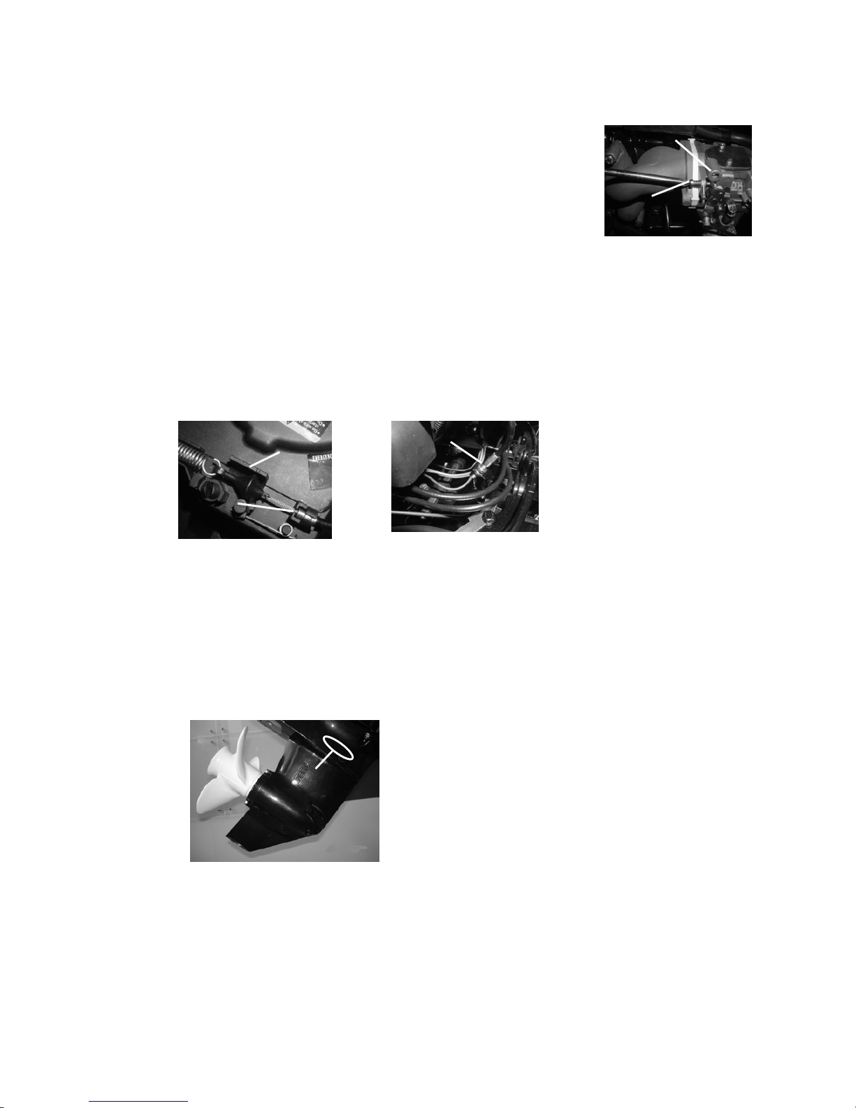
GENERAL INSPECTION
Anode
Inspect lower unit anode and engine anode (on the thermostat cover). Clean the greasy dirt and scales.
If wear or damage is above 1/2, replace the anode.
CAUTION:
Cannot grease or paint the anode, or it will not operate properly.
Grease points
1. Refer the illustration for greasing points, paint the water resistant grease.
20
2. Paint anti-corrosion grease on the propeller shaft.
Cooling water passage
1. Inspect cooling water passage, if blocked, clean it.
1. Cooling water passage inlet
1
2. Place the outboard engine in the water and ensure the water level is above the anti-vortex plate, then
start the engine.
3. Check if water overflows at the cooling water checking hole. If there is no flow or intermittent
flow, check the cooling water passage.
1
2
1. Cooling water inlet 2. Cooling water checking hole
21

Thermostat
1. Remove the thermostat cover and thermostat.
2. Hang the thermostat in a container with water.
3. Heat the container.
4. Check the valve open height under the specified water temperatures. If out of order, change it.
Water temperature Valve open height
Under 62℃ 0.1mm
Over 70℃ Over 3mm
5. Fit on the thermostat and thermostat cover, then tighten the screws to specification.
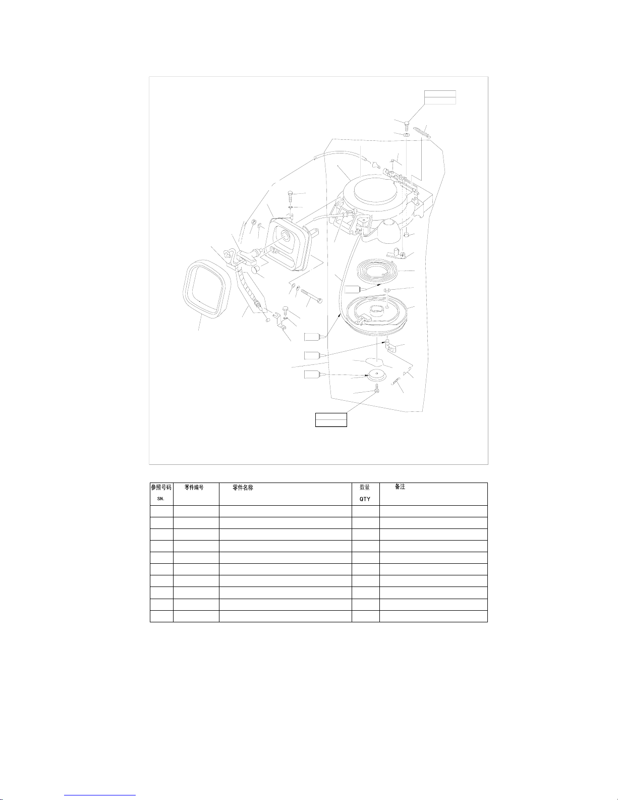
RECOIL STARTER
NOTICE
When you service, always wear safety glasses and gloves. To prevent accidental start of the engine,
remove the spark plug cap and remove stopper hang rope from stop switch assembly.
22

EXPLOSIVE DRAWING
1
2
3
4
5
6
7
8
9
10
REMARKSDESCRIPTION
PART NO.
0
M6x16 mm
7Nm
G
1
2
3
4
5
6
7
11
12
28
14
28
13
10
9
28
8
28
15
29
14
26
25
17
18
16
19
20
21
22
23
24
28
27
30
M6x20 mm
8Nm
G
G
WASHER,SPRING
COVER
HANDLE,STARTER
NUT M6
BOLT M6x90
BOLT M6x25
COLLAR
FRAME,STARTER
CASE,STARTER
STARTER ASSY
1
F4-04130102
F4-04130101
1
1
1
1
六角螺母M6
六角螺栓M6x90
弹簧垫圈6
起动手柄盖
起动手柄
GB/T6170-M6
GB/T93-6
GB/T5782-M6x90
2
1
1
1
1
六角螺栓M6x25
起动罩外壳
起动架组合
起动绳导向管
起动罩组件
F4-04130013
F15-07130101
F15-07130300
GB/T5783-M6x25
F15-07130000
23
11
12
13
14
15
16
17
18
19
20
REMARKSDESCRIPTION
PART NO.
F15-07130201
F15-07130304
GB/T5783-M6x20
F15-05000028
F15-07130305
F15-05000027
GB/T896-8
F15-07130107
F15-07130202
F15-07130204
起动轮
发泡密封圈
六角螺栓M6x20
制动器钢索固定架
制动器钢索组件
橡胶堵头
开口档圈8
涡形弹簧
起动卡瓣
卡瓣钢丝连杆
1
1
1
1
1
1
1
1
1
3
ARRESTER TIGHTWIRE ASSY
BOLT M6x20
GROMMET
SEAL,FROTHY RUBBER
LINK,PAWL
WHEEL,START-UP
CIRCLIP 8
SPRING,VOLUTE
PAWL,DRIVE
FRAME,ARRESTER TIGHTWIRE
0
M6x16 mm
7Nm
G
1
2
3
4
5
6
7
11
12
28
14
28
13
10
9
28
8
28
15
29
14
26
25
17
18
16
19
20
21
22
23
24
28
27
30
M6x20 mm
8Nm
G
G
24
 Loading...