

Page 1

CK5000New
- Hands
-
Free Car Kit Modules Datasheet
Security Level of this Document
Created by : Reference Title
Sebastien LAVAL SLA-2008-001
Revised by : Date edition N° :
Sebastien LAVAL 05/09/2008 1.02
Approved by : Date Function
Fabien LEA 05/09/2008 OEM Program Manager
1 (24)
CK5000New - Hands-Free Car Kit
Modules Datasheet
Page 2
CK5000New
- Hands
-
Free Car Kit Modules Datasheet
Security Level of this Document
Created by : Reference Title
Sebastien LAVAL SLA-2008-001
Revised by : Date edition N° :
Sebastien LAVAL 05/09/2008 1.02
Approved by : Date Function
Fabien LEA 05/09/2008 OEM Program Manager
HISTORY
Rev Date Author Description
0.9 28/12/2007 F. LEA Add precision regarding Combo memory and RAM technology
0.91 09/01/2008 S.LAVAL - Refresh document layout
- Review features list
- Update block diagram §1.2
- Add 26 MHz oscillator in §2.2
- Remove Power Supply description on §2.4
- Update external circuit in § 2.6: Replace LM4665 by op-amp
stage
- Update connector specification
0.92 06/02/2008 S.LAVAL - New description for software architecture
0.93 29/02/2008 S.LAVAL - Mechanical design update
0.94 31/03/2008 S.LAVAL - Connector pin out drawing review
0.95 16/04/2008 S.LAVAL - Add mechanical specification for horizontal module
- Add motherboard integration for horizontal module
- Start-up sequence update
- Update mechanical specification for vertical module
- Add FCC ID and legal notice
1.00 29/08/2008 S.LAVAL - Update overall document format
- Correct AC output level
- Review § 4.5.3
1.01 02/09/2008 S.LAVAL - Revise §4.3
2 (24)
1.02 05/09/2008 S.LAVAL - Add CE Declaration
- Update §6 BLUES description
- Update §4.5.3.3
- Update Absolute maximum ratings §4.3
REFERENCE DOCUMENTS
N° Reference Rev Title
[1] PN
Page 3

CK5000New
- Hands
-
Free Car Kit Modules Datasheet
Security Level of this Document
Created by : Reference Title
Sebastien LAVAL SLA-2008-001
Revised by : Date edition N° :
Sebastien LAVAL 05/09/2008 1.02
Approved by : Date Function
Fabien LEA 05/09/2008 OEM Program Manager
TABLE OF CONTENTS
PRODUCT OVERVIEW .......................................................................................................................................... 4
1
3 (24)
1.1 CK5000N
1.2 C
2 ELECTRICAL ARCHITECTURE................................................................................................................................. 6
2.1 B
2.2 M
3 CONNECTOR PIN-OUT ......................................................................................................................................... 8
4 ELECTRICAL CHARACTERISTICS ............................................................................................................................ 9
4.1 P
4.2 P
4.3 A
4.4 B
4.5 E
4.6 E
5 MODULE LAYOUT ...............................................................................................................................................14
6 SOFTWARE SPECIFICATIONS ..............................................................................................................................15
6.1 S
6.2 S
ONFIGURATIONS
LOCK DIAGRAM
OWER CONSUMPTION
OWER SUPPLY
BSOLUTE MAXIMUM RATINGS
LUETOOTH RADIO LINK
LECTRICAL SPECIFICATIONS
4.5.1 UART interface ............................................................................................................................................ 9
4.5.2 Reset ......................................................................................................................................................... 10
4.5.3 Audio Interface .......................................................................................................................................... 11
XTERNAL DESIGN (ANALOG INTERFACE
OFTWARE FUNCTIONALITIES
OFTWARE ARCHITECTURE
EW FEATURES
.................................................................................................................................................... 5
...................................................................................................................................................... 6
AIN COMPONENTS
........................................................................................................................................................ 9
........................................................................................................................................... 4
................................................................................................................................................ 7
............................................................................................................................................. 9
................................................................................................................................... 9
............................................................................................................................................ 9
....................................................................................................................................... 9
) ..................................................................................................................... 13
................................................................................................................................... 15
...................................................................................................................................... 16
7 MECHANICAL CHARACTERISTICS ........................................................................................................................17
7.1 M
7.2 C
7.3 M
8 APPROVALS / CERTIFICATIONS ...........................................................................................................................22
8.1 BLUETOOTH Q
8.2 FCC / CE C
8.3 CE D
8.4 ROHS D
9 DEVELOPMENT TOOLS .......................................................................................................................................24
ECHANICAL SPECIFICATIONS – MODULE WITH
7.1.1 Vertical version: ........................................................................................................................................ 17
7.1.2 Horizontal version: .................................................................................................................................... 18
7.1.3 Shield specifications: ................................................................................................................................. 18
ONNECTOR SPECIFICATION
OTHERBOARD INTEGRATION
7.3.1 Vertical module – Mechanical integration: ............................................................................................... 19
7.3.2 Horizontal version – Mechanical integration: ........................................................................................... 20
7.3.3 Mother board interface connector MOLEX 52465-1470: .......................................................................... 21
UALIFICATION
OMPLIANCE
8.2.1 CK5000New with internal BT antenna ...................................................................................................... 22
8.2.2 CK5000New with external BT antenna ..................................................................................................... 23
ECLARATION
................................................................................................................................................... 23
ECLARATION
: .................................................................................................................................... 18
.................................................................................................................................. 19
................................................................................................................................. 22
........................................................................................................................................... 22
............................................................................................................................................. 23
PCB
ANTENNA
....................................................................................... 17
Page 4

CK5000New
- Hands
-
Free Car Kit Modules Datasheet
Security Level of this Document
Created by : Reference Title
Sebastien LAVAL SLA-2008-001
Revised by : Date edition N° :
Sebastien LAVAL 05/09/2008 1.02
Approved by : Date Function
Fabien LEA 05/09/2008 OEM Program Manager
4 (24)
1 PRODUCT OVERVIEW
This document is the Datasheet of the Parrot CK5000New Bluetooth Module.
The CK5000New is a feature-rich Bluetooth platform designed for the integration in car audios, car telematic
systems or any systems requiring a complete embedded Bluetooth solution.
1.1 CK5000New Features
Full Bluetooth Hands Free solution:
o Phone call
o Phone Book synchronisation
o Message synchronisation
Bluetooth:
o Bluetooth Power Class2 Radio
o Bluetooth specification v2.0
o All profiles supported
o Compatible with all Bluetooth phones
Digital Signal Processing:
o Acoustic Echo cancellation
o Noise Reduction
o Robust voice recognition for name dialling (speaker dependent)
Compatibility Management:
o Pairing and connection with all Bluetooth Devices: Phones, smartphones, PDA …
o Phone Book Synchronization with all devices.
o Offer of numerous characters sets (European, Russian, Chinese, Japanese…)
Hardware:
o P4+ ASIC (64MHz core frequency)
o Infineon Bluetooth chip PMB 8753
o UART interface (up to 460800 bauds)
o Internal crystal oscillator 26 MHz
o Module dimensions: 28x 32.45mm
o External interface: 14 pins board to board connector
o Possibility of internal or external antenna
Page 5
CK5000New
- Hands
-
Free Car Kit Modules Datasheet
Ordering
Security Level of this Document
Created by : Reference Title
Sebastien LAVAL SLA-2008-001
Revised by : Date edition N° :
Sebastien LAVAL 05/09/2008 1.02
Approved by : Date Function
Fabien LEA 05/09/2008 OEM Program Manager
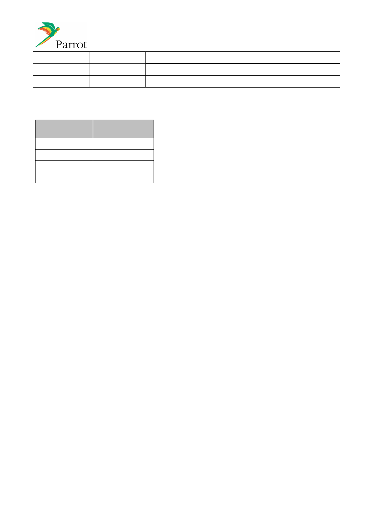
1.2 Configurations
5 (24)
Reference
Module Type
PF240015xx CK5000New HIA
PF240016xx CK5000New VIA
PF240017xx CK5000New HEA
PF240018xx CK5000New VEA
HIA : Horizontal version – Internal Antenna
HEA : Horizontal version – External Antenna
VIA : Vertical Version – Internal Antenna
VEA : Vertical Version – External Antenna
Page 6
CK5000New
- Hands
-
Free Car Kit Modules Datasheet
Bluetooth
DSP functions
Voice
PCM 8kHz 16 bits
Flash
SRAM
AT Commands, DUN, SPP data
UART (Tx and Rx) up to
460kpbs
HCI Transport layer
Bluetooth Stack and profiles
Power supply
Microphone
Voice
Bluetooth PCM
PCM 8kHz 16 bits
CK5000
New
Security Level of this Document
Created by : Reference Title
Sebastien LAVAL SLA-2008-001
Revised by : Date edition N° :
Sebastien LAVAL 05/09/2008 1.02
Approved by : Date Function
Fabien LEA 05/09/2008 OEM Program Manager
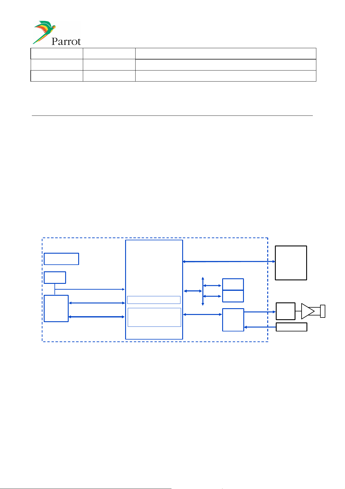
2 ELECTRICAL ARCHITECTURE
2.1 Block diagram
The main electrical interfaces provided by the CK5000New are:
Audio:
o 1 audio input (analogical)
o 1 audio output (analogical)
6 (24)
Serial Link:
o UART for the software interface through AT commands (refer to [1])
Power Supply:
o 3.3V
and reset
26 MHz
oscillator
Controller
UART 4-wire up to 460kbps
P4+
Echo Cancellation
Noise Reduction
Voice Recognition
16Mb
2Mb
Voice
Codec
Voice
Analog out
Analog in
HOST
CPU
DSP or
CODEC
AMP
CK5000New block diagram
Page 7

CK5000New
- Hands
-
Free Car Kit Modules Datasheet
Security Level of this Document
Created by : Reference Title
Sebastien LAVAL SLA-2008-001
Revised by : Date edition N° :
Sebastien LAVAL 05/09/2008 1.02
Approved by : Date Function
Fabien LEA 05/09/2008 OEM Program Manager
2.2 Main components
The main components are:
Parrot4+ ASIC
Bluetooth module Infineon PMB8753
Combo Ram/Flash : 2 Mbits or 4Mbits SRAM memory & 16 Mbits flash memory
Codec : 16 bits PCM 8kHz audio codec for converting audio signals between analog and digital
formats
26 MHZ oscillator
7 (24)
BT antenna: 2 different configurations available (on PCB F-inverted Antenna or coaxial connector for
remote antenna).
Page 8
CK5000New
- Hands
-
Free Car Kit Modules Datasheet
INPUT
Security Level of this Document
Created by : Reference Title
Sebastien LAVAL SLA-2008-001
Revised by : Date edition N° :
Sebastien LAVAL 05/09/2008 1.02
Approved by : Date Function
Fabien LEA 05/09/2008 OEM Program Manager
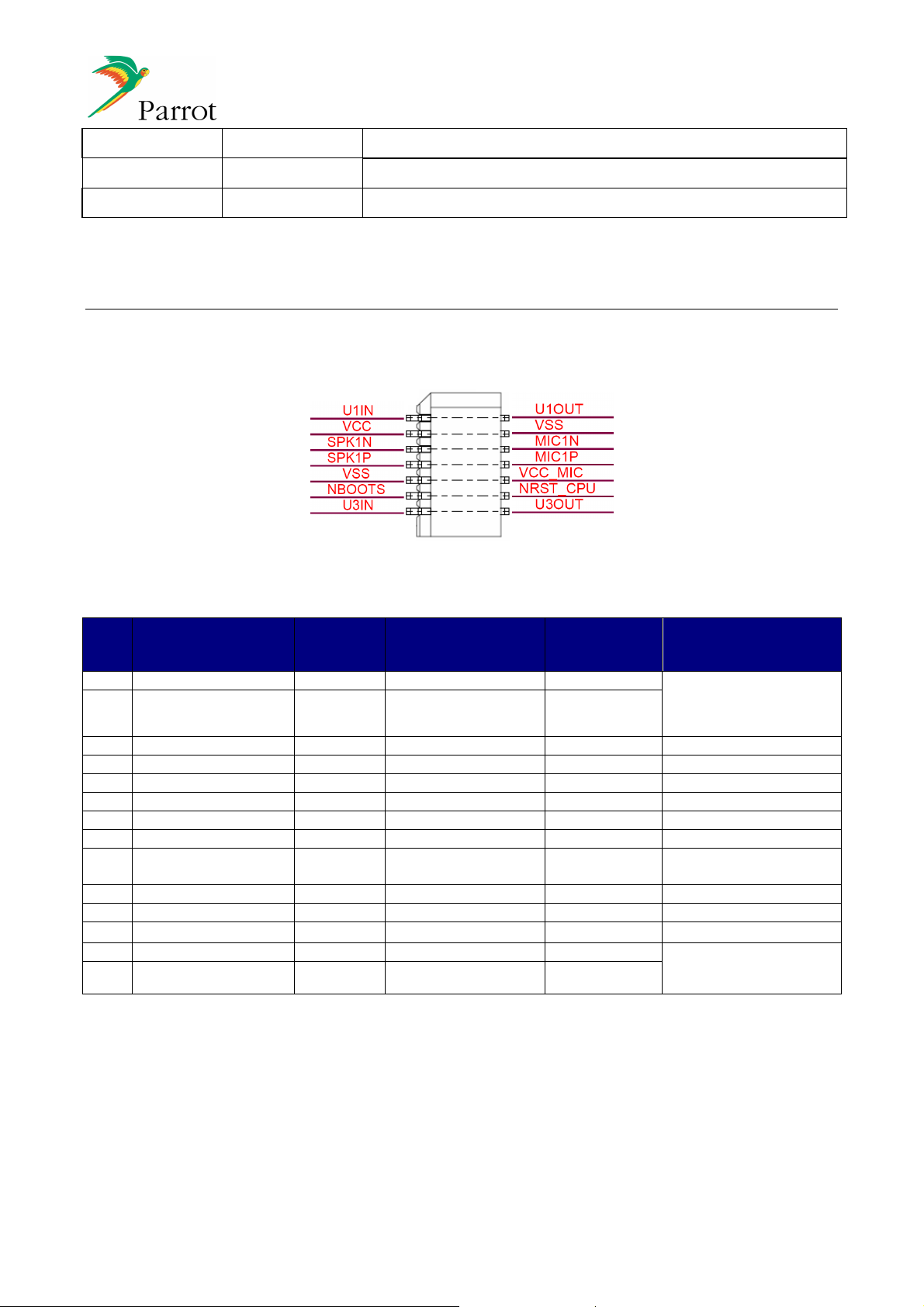
3 CONNECTOR PIN-OUT
The following pin-out allows an interface to the CK5000New according to market standards:
8 (24)
1
14 pins connector
PIN
FUNCTION
/ OUTPUT
/ POWER
TYPICAL VOLTAGE
MAXIMAL
CURRENT
COMMENT
1 U1OUT O 3.3V 10mA 16C550 Compatible
type
2 U1IN I 3.3V 1mA
(for Flash Update interface
and host AT commands)
3 VSS P 0V 1A GROUND
4 VCC P 3.3V (±0.1V) 1 A
5 MIC1N I 0V 15mA Analogical audio input
6 SPK1N O 1.65V
7 MIC1P I 2.5V
8 SPK1P
(3)
O 1.65V
9 VCC_MIC P 3.3V 1mA
(2)
10mA Analogical audio output
(2)
1mA Analogical audio input
(2)
10mA Analogical audio output
Microphone bias
voltage
10 VSS P 0V 1A GROUND
11 NRST_CPU
(1)
I 3.3V 3mA RESET trigger Input
12 NBOOTS I 3.3V 1mA Flash update
13 U3OUT O 3.3V 10mA 16C550 Compatible
type
14 U3IN I 3.3V 1mA
Notes:
1) Internal pull up.
2) Mean value.
3) SPK Output pins are differential outputs with Vcc/2 mean value.
(for Debug interface)
Page 9

CK5000New
- Hands
-
Free Car Kit Modules Datasheet
Operating
modes
Current
Comment
standby mode
active mode
Security Level of this Document
Created by : Reference Title
Sebastien LAVAL SLA-2008-001
Revised by : Date edition N° :
Sebastien LAVAL 05/09/2008 1.02
Approved by : Date Function
Fabien LEA 05/09/2008 OEM Program Manager
4 ELECTRICAL CHARACTERISTICS
4.1 Power consumption
The CK5000New features two different operating modes allowing low-power consumption:
<40 mA BT module in park/sniff mode , Parrot4+ ASIC in idle
<200 mA All components active
9 (24)
4.2 Power supply
DC input supply voltage……………………………………………………………………………………3.3V (±0.1V)
Maximum allowed ripple………………………………………………………………………………..……30 mV rms
Peak current: 1A during 1.2ms during switch ON.
4.3 Absolute maximum ratings
Operating temperature range………………………………………………………………………….-40°C to +85°C
Storage temperature range…………………………………………………………………………….-20°C to +50°C
Non-operating temperature range……………………………………………………………...……-40°C to +125°C
DC input supply voltage range....…………………………………………………………………………3.2V to 3.6V
ESD sensitivity according to IEC610000-4-2….……………………………………………………………..….±2KV
4.4 Bluetooth Radio link
The module is optionally equipped with internal PCB antenna or a connector for external antenna.
The line impedance from RF output to connector (over Bluetooth frequency range) is 50 Ohm.
4.5 Electrical specifications
4.5.1 UART interface
UART 1 and 3 are 16C550 Compatible Type.
Default transmission speed is 115200bps, max speed is 460800 bps
A bit “Start Bit=0” is added to the beginning of each word (8bits).
A “Stop Bit=1” is sent by the transmitter at the end of each word.
No parity
Page 10

CK5000New
- Hands
-
Free Car Kit Modules Datasheet
UART1 / UART3
Min Typ Max Unit Comment
RESET
Min Typ Max Unit Comment
Security Level of this Document
Created by : Reference Title
Sebastien LAVAL SLA-2008-001
Revised by : Date edition N° :
Sebastien LAVAL 05/09/2008 1.02
Approved by : Date Function
Fabien LEA 05/09/2008 OEM Program Manager
The Least Significant Bit (LSB) is sent first
Input High Level 2.5 -- Vcc V NC
Input Low Level -- -- 0.5 V NC
Output High Level Vcc-0.3 -- N/A V at IOH = 0,1mA
(open collector with
build-in 2,5k pull-up)
Output Low Level -- -- 0.4 V at IOL = 2mA
Rise Time versus Load
-- 1300 1900 ns C = 100 pF
Capacitance for Output
Fall Time versus Load
Capacitance for Output
-- 240 350 ns C = 100 pF
10 (24)
4.5.2 Reset
Asynchronous reset signal used to reset the module, active low.
Reset Time 50 -- -- µs NC
Active Level -- -- 0.2 V NC
Non Active Level 2.5 -- N/A V NC
The Switching ON and OFF procedures are described below.
4.5.2.1 Switch ON sequence:
The signal “NRST_CPU” on the host interface is forced to a logical zero value by host until the supply
voltage reached its nominal value.
- The host switches its signal “NRST_CPU” to a logical one value allowing the module to turn on its
supply.
- After 280ms, the power supply is stabilized and then triggers the start of the ASIC
4.5.2.2 Switch OFF sequence:
- The host sends the "sleep” AT command: AT*POFF [1].
- The ASIC disconnects any BT link.
- The ASIC sends the "sleep acknowledgement" AT event and then stops the UART link [1].
- The host switches the reset to a zero logical value.
If the host switches the “NRST_CPU” to zero level for at least 5 µs but no more than 4ms the module will be
reset.
Page 11

CK5000New
- Hands
-
Free Car Kit Modules Datasheet
AUDIO In
put (Analogical)
Min Typ Max Unit Comment
Security Level of this Document
Created by : Reference Title
Sebastien LAVAL SLA-2008-001
Revised by : Date edition N° :
Sebastien LAVAL 05/09/2008 1.02
Approved by : Date Function
Fabien LEA 05/09/2008 OEM Program Manager
4.5.3 Audio Interface
4.5.3.1 Microphone interface
The below schematic details internal microphone stage:
11 (24)
CK5000New is designed to be used with an electret condenser microphone with impedance less than
2.2kOhms.
Recommended electrical characteristics of the microphone:
•
Operating voltage: 1.5V-3.6V DC
•
Current consumption: 500µA max.
•
Use of pre-amplified microphones is in option.
4.5.3.2 Microphone power supply
Supply voltage 3.3V for microphone.
Decoupling capacitor required on main board (470µF – 6V3 with ESR<10 ohm at low temperature)
4.5.3.3 Characteristics
Input Impedance TBD TBD 2200 Ohm NC
DC Input Voltage (BIAS Voltage) TBD 2.5 TBD NC
Common Mode Rejection Ratio
@1kHz
Signal To Noise Ratio TBD TBD -- dB NC
(THD + N)/S TBD TBD -- dB NC
High Cut Frequency (-3dB) -- 3.4 -- kHz NC
Low Cut Frequency (-3dB) -- 200 -- Hz NC
30 TBD -- dB NC
Page 12

CK5000New
- Hands
-
Free Car Kit Modules Datasheet
AUDIO Output (Analogic
al)
Min Typ Max Unit Comment
Security Level of this Document
Created by : Reference Title
Sebastien LAVAL SLA-2008-001
Revised by : Date edition N° :
Sebastien LAVAL 05/09/2008 1.02
Approved by : Date Function
Fabien LEA 05/09/2008 OEM Program Manager
4.5.3.4 Speaker interface
SPK1N and SPK1P are differential outputs capable of driving a 1kOhms load with 2.94V peak-to-peak.
The signal mean value is Vcc/2.
Drive Load Capability 1000 -- -- Ohm NC
AC Output Level -- -- 0.85 V rms NC
DC output voltage Vcc/2 -
0.2
THD -- TBD TBD % NC
High Cut Frequency (-3dB) -- 3.6 -- kHz NC
Low Cut Frequency (-3dB) -- 200 -- Hz NC
Out Put Noise -- TBD TBD µV NC
Signal To Noise Ratio -- TBD -- dB NC
Power Supply Rejection -- TBD -- dB NC
Vcc/2 Vcc/2
+0.2
V NC
12 (24)
Page 13

CK5000New
- Hands
-
Free Car Kit Modules Datasheet
Example of a
udio stage interface on
Security Level of this Document
Created by : Reference Title
13 (24)
Sebastien LAVAL SLA-2008-001
Revised by : Date edition N° :
Sebastien LAVAL 05/09/2008 1.02
Approved by : Date Function
Fabien LEA 05/09/2008 OEM Program Manager
4.6 External design (analog interface)
Audio Pins SPK1P, SPK1N, MIC1P and MIC1N must be protected from noise.
Isolate U1IN, U1OUT, U3IN, U3OUT, SPK1P, SPK1N, MIC1P, MIC1N, NRST_CPU and VSS by 0R
resistors (RF: 0603) and use ferrites in case of EMC disturbances.
Page 14

CK5000New
- Hands
-
Free Car Kit Modules Datasheet
Security Level of this Document
Created by : Reference Title
Sebastien LAVAL SLA-2008-001
Revised by : Date edition N° :
Sebastien LAVAL 05/09/2008 1.02
Approved by : Date Function
Fabien LEA 05/09/2008 OEM Program Manager
5 MODULE LAYOUT
14 (24)
Page 15

CK5000New
- Hands
-
Free Car Kit Modules Datasheet
Security Level of this Document
Created by : Reference Title
Sebastien LAVAL SLA-2008-001
Revised by : Date edition N° :
Sebastien LAVAL 05/09/2008 1.02
Approved by : Date Function
Fabien LEA 05/09/2008 OEM Program Manager
6 SOFTWARE SPECIFICATIONS
Bluetooth Stack
HCI (Host Controller interface),
L2CAP (Logical Link Control and Adaptation Protocol),
RFCOMM (TS011...),
SDP (Service Discovery Protocol),
OBEX (IrDA Object Exchange).
15 (24)
Bluetooth Profiles Supported
BLUES 2.0
Generic Access Profile
GAP
Phone Management
HFP 0.96 - 1.0 - 1.5
HSP 1.0
Phone Book
PBAP 1.0
SYNC 1.1 (IrMC SYNC over BT)
OPP 1.0 Server/Client (Vcard 2.1)
GSM 07.07 AT Commands
Nokia synchronization protocol
Others
SPP 1.1
DUNP 1.1
Software update over SPP
6.1 Software Functionalities
The main target of the software interface is to provide a high level command set, hiding the internal
complexity of the Bluetooth function and the variability of its standard across different devices.
This software interface is based on well-known AT commands. Some of these commands are directly
derived from the GSM 07.07 recommendation and from the appropriate Bluetooth profiles.
Some supplementary commands are used to manage Bluetooth related functions like device pairing and
connection management as well as the acoustic and speech recognition functions.
AT commands are detailed in [1].
Page 16

CK5000New
- Hands
-
Free Car Kit Modules Datasheet
Bluetooth stack +
Devices
Audio
PBAP
SPP
HFP
-
AG
SYNC
Nokia
-
Sync
Security Level of this Document
Created by : Reference Title
Sebastien LAVAL SLA-2008-001
Revised by : Date edition N° :
Sebastien LAVAL 05/09/2008 1.02
Approved by : Date Function
Fabien LEA 05/09/2008 OEM Program Manager
6.2 Software Architecture
CK5000New software architecture can be decomposed as showed on the diagram below.
CK5000New Application
BLUES
16 (24)
Profiles
Management
Management
ParrotOS
BLUES supports Unicode, which allows the management of accents and phonebook in any language. It has
also a friendly and flexible MMI. One can use BLUES with a simple single or double key interface as well as
a diversity of graphic displays.
For information, here is a description of Bluetooth stack and Bluetooth profiles in BLUES.
OPP
DUN - C
OBEX
HSP
HFP
Generic Access Profile : L2CAP + Kernel
RFCOMM SDP
Host Control Interface - HCI
Page 17

CK5000New
- Hands
-
Free Car Kit Modules Datasheet
Security Level of this Document
Created by : Reference Title
17 (24)
Sebastien LAVAL SLA-2008-001
Revised by : Date edition N° :
Sebastien LAVAL 05/09/2008 1.02
Approved by : Date Function
Fabien LEA 05/09/2008 OEM Program Manager
7 MECHANICAL CHARACTERISTICS
The CK5000New features a female connector allowing a connection to the motherboard through a male
connector.
The CK5000New exists in two mechanical configurations, with either a vertical or a horizontal mounting onto
the mother board. Each mechanical configuration is realised by the mounting of a specific PCB shield and
the appropriate 14 pins connector.
For both version fixation to the mother board is assured by the PCB shield.
7.1 Mechanical specifications – module with PCB antenna
These dimensions are stated on a preliminary basis.
7.1.1 Vertical version:
Page 18

CK5000New
- Hands
-
Free Car Kit Modules Datasheet
Security Level of this Document
Created by : Reference Title
Sebastien LAVAL SLA-2008-001
Revised by : Date edition N° :
Sebastien LAVAL 05/09/2008 1.02
Approved by : Date Function
Fabien LEA 05/09/2008 OEM Program Manager
7.1.2 Horizontal version:
18 (24)
7.1.3 Shield specifications:
For vertical version, refer to annex documents: PAR_ME0040-B-080625.pdf and PAR_ME0041-B-
080625.pdf.
For horizontal version, refer to annex documents: CK5000NEW Frame2 19004197_P7.pdf and
PAR_ME0041-B-080625.pdf
7.2 Connector specification:
Respectively vertical and horizontal versions of the CK5000New module mount interface connector: MOLEX
053309-1470 and MOLEX 053307-1471.
Datasheets are proposed as annexe documents.
Page 19

CK5000New
- Hands
-
Free Car Kit Modules Datasheet
Security Level of this Document
Created by : Reference Title
Sebastien LAVAL SLA-2008-001
Revised by : Date edition N° :
Sebastien LAVAL 05/09/2008 1.02
Approved by : Date Function
Fabien LEA 05/09/2008 OEM Program Manager
7.3 Motherboard Integration
Mechanical constraints for the integration on the mother board are detailed below.
7.3.1 Vertical module – Mechanical integration:
19 (24)
Page 20

CK5000New
- Hands
-
Free Car Kit Modules Datasheet
Security Level of this Document
Created by : Reference Title
Sebastien LAVAL SLA-2008-001
Revised by : Date edition N° :
Sebastien LAVAL 05/09/2008 1.02
Approved by : Date Function
Fabien LEA 05/09/2008 OEM Program Manager
7.3.2 Horizontal version – Mechanical integration:
20 (24)
Page 21

CK5000New
- Hands
-
Free Car Kit Modules Datasheet
Security Level of this Document
Created by : Reference Title
Sebastien LAVAL SLA-2008-001
Revised by : Date edition N° :
Sebastien LAVAL 05/09/2008 1.02
Approved by : Date Function
Fabien LEA 05/09/2008 OEM Program Manager
7.3.3 Mother board interface connector MOLEX 52465-1470:
21 (24)
Page 22

CK5000New
- Hands
-
Free Car Kit Modules Datasheet
Security Level of this Document
Created by : Reference Title
Sebastien LAVAL SLA-2008-001
Revised by : Date edition N° :
Sebastien LAVAL 05/09/2008 1.02
Approved by : Date Function
Fabien LEA 05/09/2008 OEM Program Manager
8 APPROVALS / CERTIFICATIONS
8.1 BLUETOOTH Qualification
To be completed after product qualification.
8.2 FCC / CE Compliance
8.2.1 CK5000New with internal BT antenna
22 (24)
FCC ID: RKXCK50OONVIA
In accordance with FCC Part 15, the CK5000New is listed as a Limited Modular Transmitter device.
In support of the Modular Transmitter Approval, the following is stated:
The module does have buffered modulation / data inputs.
The module have a permanently attached antenna.
The module have its own RF shielding
The module can be tested as a stand-alone device.
The module is labeled with the proper FCC ID, and labeling instructions are provided to OEM end
users for external product labels.
The module does have instruction for proper use.
The module does meet the FCC RF regulations.
Limited Modular Transmitter Approval, is granted, instead of Modular Transmitter Approval, because the
following condition is not met:
The module does not have to regulate its own power supply.
Module CK5000New is labelled with its own FCC number on its shielding, and, if the FCC ID is not visible
when the module is installed inside final device, then the outside of the device into which the module is
installed must also display a label referring to the enclosed module. This exterior label can use wording such
as the following: “Contains Transmitter Module FCC ID: RKXCK5000NVIA” or “Contains FCC ID:
RKXCK5000NVIA.” Any similar wording that expresses the same meaning may be used.
Module CK5000New can not be integrated in a final device which is connected to the AC power lines. It is
necessary that final device must be supplied by a battery.
FCC RF exposure requirements: This device and its antenna(s) must not be collocated or operating in
conjunction with any other antenna or transmitter.
THIS DEVICE COMPLIES WITH PART 15 OF THE FCC RULES. OPERATION IS SUBJECT TO THE
FOLLOWING TWO CONDITIONS:
(1) THIS DEVICE MAY NOT CAUSE HARMFUL INTERFERENCE, AND
Page 23

CK5000New
- Hands
-
Free Car Kit Modules Datasheet
Security Level of this Document
Created by : Reference Title
23 (24)
Sebastien LAVAL SLA-2008-001
Revised by : Date edition N° :
Sebastien LAVAL 05/09/2008 1.02
Approved by : Date Function
Fabien LEA 05/09/2008 OEM Program Manager
(2) THIS DEVICE MUST ACCEPT ANY INTERFERENCE RECEIVED, INCLUDING
INTERFERENCE THAT MAY CAUSE UNDESIRED OPERATION.
NOTE: THE MANUFACTURER IS NOT RESPONSIBLE FOR ANY RADIO OR TV INTERFERENCE
CAUSED BY UNAUTHORIZED MODIFICATIONS TO THIS EQUIPMENT. SUCH MODIFICATIONS
COULD VOID THE USER’S AUTHORITY TO OPERATE THE EQUIPMENT.
8.2.2 CK5000New with external BT antenna
CK5000New with external antenna is not submitted to FCC and CE marks. Moreover, there is no “fixed”
configuration: cable (between module and antenna) and BT antenna characteristics. These 2 elements have
an impact on the EMC performances. Also, environment around the module (car radio) is an important factor.
So, FCC and CE qualifications must be done with the whole product (car radio + CK5000New)
8.3 CE Declaration
We, Parrot SA 174 quai de Jemmapes 75010 Paris France, declare under our sole responsibility that our
product (Parrot CK5050+) is in conformity with the Radio and Telecommunication equipment directive
1999/5/EC R&TTE according to the essentials requirements and respect the norms listed below:
3.1-a) Electrical Safety EN60950-1
EMF EN50371
3.1-b) EMC EN301 489-17
3.2 Radio EN300 328
Paris, September the 2nd, 2008
Qualification Manager
Arezki Guerrab
8.4 ROHS Declaration
To be completed.
Page 24

CK5000New
- Hands
-
Free Car Kit Modules Datasheet
Security Level of this Document
Created by : Reference Title
Sebastien LAVAL SLA-2008-001
Revised by : Date edition N° :
Sebastien LAVAL 05/09/2008 1.02
Approved by : Date Function
Fabien LEA 05/09/2008 OEM Program Manager
9 DEVELOPMENT TOOLS
To be released.
24 (24)
 Loading...