

ParkZone PKZ4975 User Manual
Bf-109G PNP
Instruction Manual
© 2009 Horizon Hobby, Inc.
4105 Fieldstone Road
Champaign, IL 61822
USA
Horizon Hobby UK
Units 1-4 Ployters Rd
Staple Tye
Harlow, Essex
CM18 7NS
United Kingdom
Horizon Hobby Deutschland GmbH
Hamburger Strasse 10
25335 Elmshorn
Germany
®
ParkZone
DSM and DSM2 are trademarks or registered trademarks of Horizon Hobby, Inc. The Spektrum trademark is used with permission of Bachmann Industries, Inc.
Spektrum radios and accessories are exclusively available from Horizon Hobby, Inc.
Futaba is a registered trademark of Futaba Denshi Kogyo Kabushiki Kaisha Corporation of Japan.
products are distributed exclusively by Horizon Hobby, Inc.
www.parkzone.com
Printed 7/09 15516.1
Wingspan: 43.5 in
Length: 39.4 in
Weight: 35.3 oz
Motor: ParkZone 15-size 720Kv brushless outrunner motor
ESC: E-flite 30-amp Switch-Mode BEC brushless
1
2
Bf-109G PNP Instruction Manual
Step 2
Fast, agile and armed to the teeth, Willy Messerschmitt’s
BF-109 dominated European skies at the outset of World
War II. With the exception of Britain’s Spitfire, the “109”
outclassed nearly every other fighter it faced between
1939 and 1941. In that short time, its pilots, many of
whom had honed their tactics in the Spanish Civil War,
racked up thousands of aerial victories. Now anyone can
experience the thrill of flying the Messerschmitt on a
smaller scale with this fully-aerobatic, brushless-powered
Plug-N-Play
it airborne is about as simple as it gets. Just attach the
wing and tail, install your full range receiver, charge your
battery and you’re flying.
The ParkZone
box with a realistic Luftwaffe paint scheme inspired by the
markings of a Bf-109 flown by Eric Hartmann—Germany’s
leading WWII ace. Other scale touches include landing
gear doors, exhaust stacks, gun ports and a port-side
supercharger intake.
Charge-and-Fly
performance and beautiful scale detail—with the
ParkZone Messerschmitt Bf-109G, you get it all.
™
reproduction from ParkZone. And getting
®
Messerschmitt Bf-109G comes out of the
™
convenience, outstanding fl ight
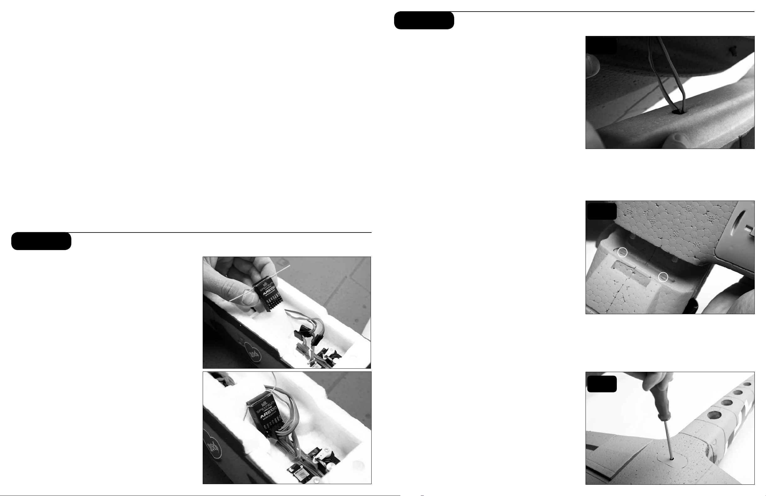
Step 1
Installing Receiver
1. Install the receiver in the location shown in the photo
using hook and loop tape or double-sided servo tape.
2. Plug in the elevator and rudder servo into the
appropriate ports of the receiver. Plug Y-harness into
the aileron channel of the receiver and plug the ESC
lead into the throttle channel.
Bf-109G PNP already has the 3-wire servos, a ParkZone
15-size low Kv outrunner brushless motor, and an E-flite
30A brushless ESC. The decals have already been
applied, as well. You will only need to add your own
1800-2200mAh battery, charger, full range transmitter
and a receiver. In as little as an hour, you can be ready
for your first flight with the Bf-109G PNP. This means you
can spend your time refining your flying skills, not your
building skills.
Warning: Although your ParkZone Bf-109G PNP comes
almost ready to fly, this aircraft is for experienced RC
pilots only and is not a toy! Misuse of the plane can
cause serious bodily harm and damage to property.
Therefore, only an experienced RC pilot should fly it.
Note: A 4-channel or greater radio is required for the
Bf-109G PNP. A 5-channel or greater will be needed if
the optional flaps are used.
Age Recommendation: 14 years or over. This is
not a toy. This product is not intended for use by
children without direct adult supervision.
®
In order to attach the wing of your Bf-109G, please follow
these simple instructions:
1. Locate the included wing-securing screw.
2. Turn over the fuselage so you are looking at the
bottom. Do the same with the wing.
3. Connect the aileron leads to the installed
Y-harness, noting proper orientation. Route the
Y-harness lead through the access hole in the bottom
of the fuselage.
4. Carefully align the two locator pins on the front of
the wing into the two small holes in the front of the
fuselage.
5. Slide the aileron leads inside the fuselage so that
they will not become pinched in between the wing
and the fuselage when securing the wing.
6. Slide the trailing edge of the wing into the fuselage
as shown, making certain it is perfectly centered.
This must be done correctly in order to allow the
screw to thread into the fuselage. Once you are
certain the wing is centered, tighten the screw to
secure the wing.
7. The wing is correctly installed when no gap exists
between the wing and fillet.
8. Gently pull up on the rear of the canopy hatch to
remove and set aside.
9. Plug the Y-harness lead into the AIL port of
the receiver.
3
4
Attaching the Wing
6
3
4
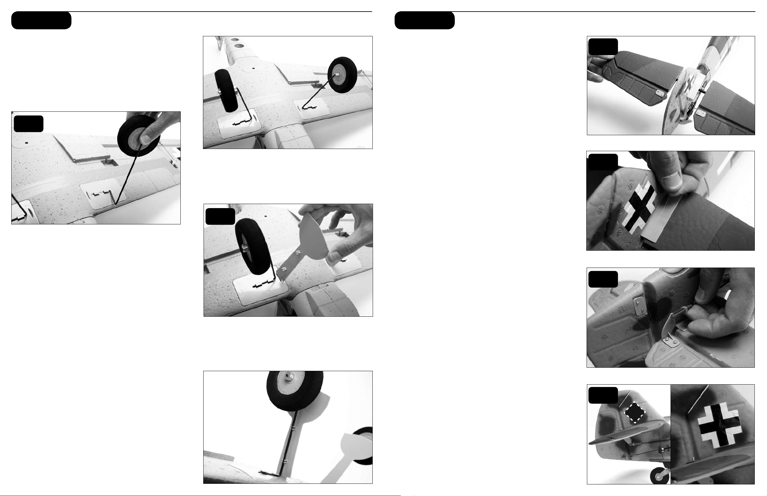
Step 3 Step 4
Installing the Landing Gear
1. Install the main landing gear by inserting it into the
locator hole in the wing. Swivel the landing gear
toward the retaining clips and gently snap into place.
2. Snap landing gear doors onto the landing gear
wire with the top of the door in the slot in the landing
gear plate.
1
2
Attaching the Horizontal Stabilizer
1. Locate the horizontal stab of the tail.
2. Slide the stab joiner rod into one side of the stab.
Slide the stab with the joiner rod through the fuselage
and then slide the opposite stab onto the fuselage.
3. Use the tape provided to properly secure the tail
to the fuselage as shown. Use the tape on the
top and bottom of each side of the tail (total of 4
applications).
4. Turn on the transmitter and plug in the flight battery.
Make sure the trim levers are centered and the left
stick is in the full down position.
5. Locate the clevis and rod exiting the sides of the
fuselage, and attach the clevis to the outermost hole
on the control horn.
6. Make sure both elevators are even to each
other by adjusting the clevises. Make any trim
adjustments as necessary prior to flight.
2
3
Note: To make trim adjustments to the horizontal
stabilizer:
a. Turn on radio transmitter.
b. Plug in fully charged battery into fuse.
c. Use the elevator trim of the radio by moving up or
down to center the tail at neutral when the gimbal is
also at neutral. If these changes are not sufficient,
center the transmitter elevator trim lever, then
remove the clevis from the control surface and
turn clevis in or out as needed to move the control
surface back to neutral.
Warning: Always keep hands and all objects away from
the propeller in case the motor is engaged. A moving
propeller can cause severe injury and/or damage.
7. Your Bf-109G is supplied with a small Maltese
cross for the tail insignia, to be applied as shown.
For those desiring a more accurate tail insignia,
an optional swastika decal is available separately
(PKZ4930, not available in all territories).
5
7
5
6
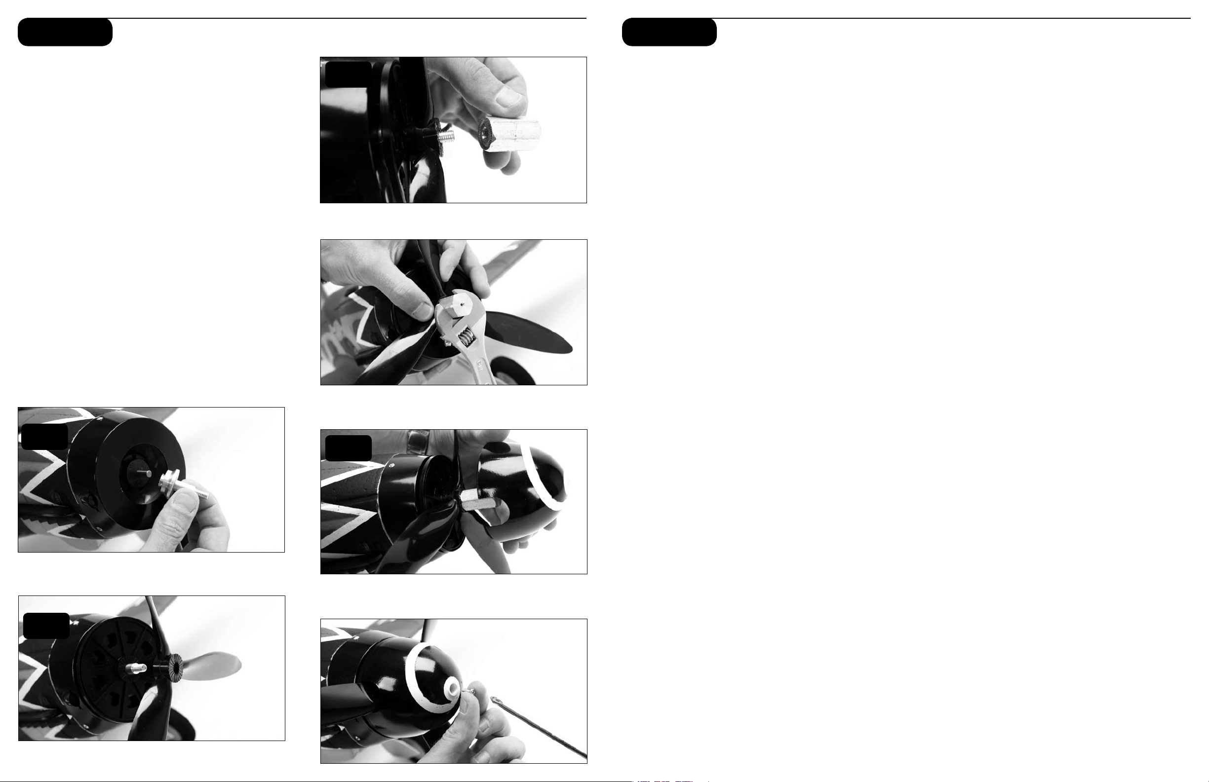
Step 5 Step 6
Installing the Propeller and Spinner
1. Slide collet onto motor shaft.
2. Slide spinner backplate followed by the propeller
onto the collet shaft.
3. Thread aluminum hex nut onto threaded collet and
tighten securely.
4. Install spinner making sure it is keyed into the
spinner backplate and using a Phillips screwdriver
install the 3mm x 10mm screw. Take care to center
the propeller blades in the cutouts of the 3-bladed
spinner, without allowing any of the blades to contact
the spinner.
Note: Another available option is the 2-bladed spinner
(PKZ4908). The included motor has a low Kv that was
engineered to match the included 3-bladed propeller. If
a two-bladed propeller is used with the stock motor, we
suggest using a 12 x 12 electric propeller. In addition,
the E-flite Apprentice motor is a higher Kv and is a dropin fit for the stock Bf-109G motor.
3
Range Checking your Radio System
After you have finished the final assembly, it is time to
range check the radio system within the Bf-109G PNP.
Prior to each flying session
• Turn on the transmitter prior to plugging in the flight
battery. With the airplane on the ground and motor
running, you should walk away approximately 100
feet and still have full control of all functions while
following the specific range test feature of your
transmitter. If this is not the case, do not fly! Call
the Horizon Support Team at 1-877-504-0233.
• Always make sure that all controls are functioning per
the transmitter input that you are giving. This includes
ailerons, rudder, elevator and throttle.
• Always make sure you have fully charged the
transmitter batteries.
• Always remove the flight battery from the
airplane when you are done flying, or when you
are on the way to the flying field.
Warning: Use of the 3-bladed prop with the Apprentice
motor will result in excess current and likely damage
the motor.
1
2
4
 Loading...