


J-3 Cub
Instruction Manual
PKZ1115
605482 14134 2
ParkZone™ products are distributed exclusively by Horizon Hobby, Inc.
4105 Fieldstone Road
Champaign, IL 61822
©2004 Horizon Hobby, Inc. www.parkzone.com
6402
SPECIFICATIONS
FM Radio: 3 Proportional Channels
Wingspan: 37.25 in
Motor: 370 w/gearbox
Length: 26.75 in Flying Weight: 15 oz

J-3 Cub Instruction Manual
Congratulations on your purchase of the ParkZone™ J-3 Cub. Your J-3 has come with everything needed to get you in the air—all in one box! You will only need to attach the wing and landing gear, as well as charge the battery prior to flight.
We at ParkZone are committed to giving you the most enjoyable flight experience possible. In order to have a safe and successful flight, we ask that you do not fly until you have read these instructions thoroughly.
Your J-3 comes with a fully proportional 3-channel FM radio system with full control of throttle, steering, and pitch. If you have not successfully flown
one of HobbyZone’s Zone 1 or 2 aircraft, or any other radio controlled aircraft, we recommend that you seek the help of an experienced radio control pilot during your beginning flights.
Crash damage is not covered under the warranty!
Your ParkZone J-3 is equipped with mode change capabilities. This software allows you to change the flight characteristics of the airplane to allow you to advance your skills. The first mode is ideal for those pilots who are transitioning from a 2-channel to a 3-channel airplane. The second mode will allow more dramatic maneuvers and aggressive flight. Get ready—your ParkZone adventures are about to begin!
Step 1
Transmitter
1.Insert 8 new “AA” batteries (supplied) into the transmitter, observing proper polarity.
2.Turn switch on to ensure the batteries have been installed correctly. Once this is confirmed, turn radio off.
Step 2
Installation of Landing Gear
1.Locate the landing gear and the included screws from within packaging.
2.Using a Phillips screwdriver, attach the landing gear to the fuselage as shown.
3 x 14mm
A 
 B
B
8.4V–600mAh  Ni-MH Battery
 Don’t connect until
just before flight.
2
Step 3
Attaching the Wing
1.Locate wing, wing struts and rubberbands.
2.Locate wing strut screws.
3.Place wing on top of fuselage so that it is centered.
4.Attach wing struts with the mounting screws as shown. There should be the same amount of slack in each strut once this is completed.
5.Once you are satisfied the wing is properly centered and the struts are properly attached, complete the attachment of the wing with the included rubber bands. Stretch two of the rubber bands from the front to the rear attach points. Stretch the next two diagonally across the middle. Confirm the wing is securely attached.
6.Make sure that prior to each flight the wing is properly centered onto the fuselage. If the wing is not centered properly, it is impossible to have correct flight.
Fix wing securely to fuselage. Loss of wing will result in lack of control and crash.
Use 4 rubber bands to secure wing 
as shown.
(2) 2.5 x 12mm
Align to the center.
A’ |
A” |
 A’=A”
A’=A”  Parallel
Step 4
Charging the Aircraft Battery
This charger uses unique peak detection circuitry that ensures an accurate charge every time and protects your Ni-Cd and Ni-MH batteries from the dangers of over-charging. This charger continually monitors the battery’s charge curve and automatically stops charging when the peak charge is detected. The peak detection charger will help avoid damaging Ni-Cd and Ni-MH cells. Your charger will also charge some other battery packs.
Important: The J-3 airplane battery should be charged shortly before flying. If you charge the battery 12 to 24 hours prior to flying, you will need to “re-peak” the battery before you fly by repeating the steps on page 4 (in Step 4 continued).
BATTERY CAPACITY |
MAX. CHARGE RATE |
CHARGE TIME |
|
|
|
|
|
300mAh 6.0V Ni-MH |
.4 amps |
40 minutes |
Note: Charge times are |
600mAh |
|
|
estimates only of fully |
4.8V–8.4V Ni-MH |
.8 amps |
40 minutes |
discharged battery |
900mAh |
|
|
pack. Actual charge |
7.2V–8.4V Ni-MH |
1.2 amps |
40 minutes |
times may vary. |
3
Step 4 |
continued |
|
DC Peak |
Features: |
Note: Damage to the charger and battery will |
• Variable |
0.3–1.2 amps |
occur if you exceed the maximum charge rate |
• Trickle |
|
recommended. |
• Uses |
outlet |
Note: Do not leave the charger and battery |
• Charges |
Cd and Ni-MH |
unattended during the charge process. While |
battery |
|
charging, place the battery on a heat resistant |
• LED |
|
surface and constantly monitor the temperature |
|
|
of the battery pack. If the battery becomes hot at |
Charging |
|
any time during the charge process, discontinue |
1. Using |
of the charger, |
charging immediately. Do not allow children to |
select |
.9 amps. |
charge battery packs without adult supervision. |
Battery |
600mAh Ni-MH |
|
Max |
amps |
|
T |
40 minutes |
|
2. Connect |
to the charger using |
|
the |
|
|
3. Connect |
the 12V power outlet |
|
in |
LED will continually |
|
blink |
charges. |
|
4. |
the LED indicator |
|
glows |
also notice at this |
|
time |
warm to the touch. |
|
Step 5
Motor Test |
|
|
1. |
Make |
slider is in the “off” |
|
position |
|
2. |
Turn |
|
3. |
Remove |
bottom of the |
|
fuselage |
in Step 2 on page 2.) |
4. |
Plug |
into the black lead |
|
inside |
|
5. |
Secure |
cavity and |
|
replace battery cap. |
|
6.Your J-3 has a built-in throttle-arming feature which needs to “see” the throttle slider in the off position before it will spin the propeller.
(CAUTION: Make sure that you, as well as loose clothing and hair, are away from propeller at all times!) Advance the throttle forward and the propeller should spin at a high speed. The throttle-arming feature will need to be activated each time the battery is plugged into the airplane.
7.When finished with the motor test, continue to Tail Control Test on next page.
ON
OFF 
Adult Supervision Required
WARNING: Keep everything clear of the propeller and hold the plane securely. A moving propeller can cause severe injury.
Step 6
Tail Control Test
Warning: Keep everything clear of the propeller before starting the control test in the event that you accidentally turn on the motor.
1.Be certain that the throttle slider is in the “Off” position. Make certain both trim levers are centered.
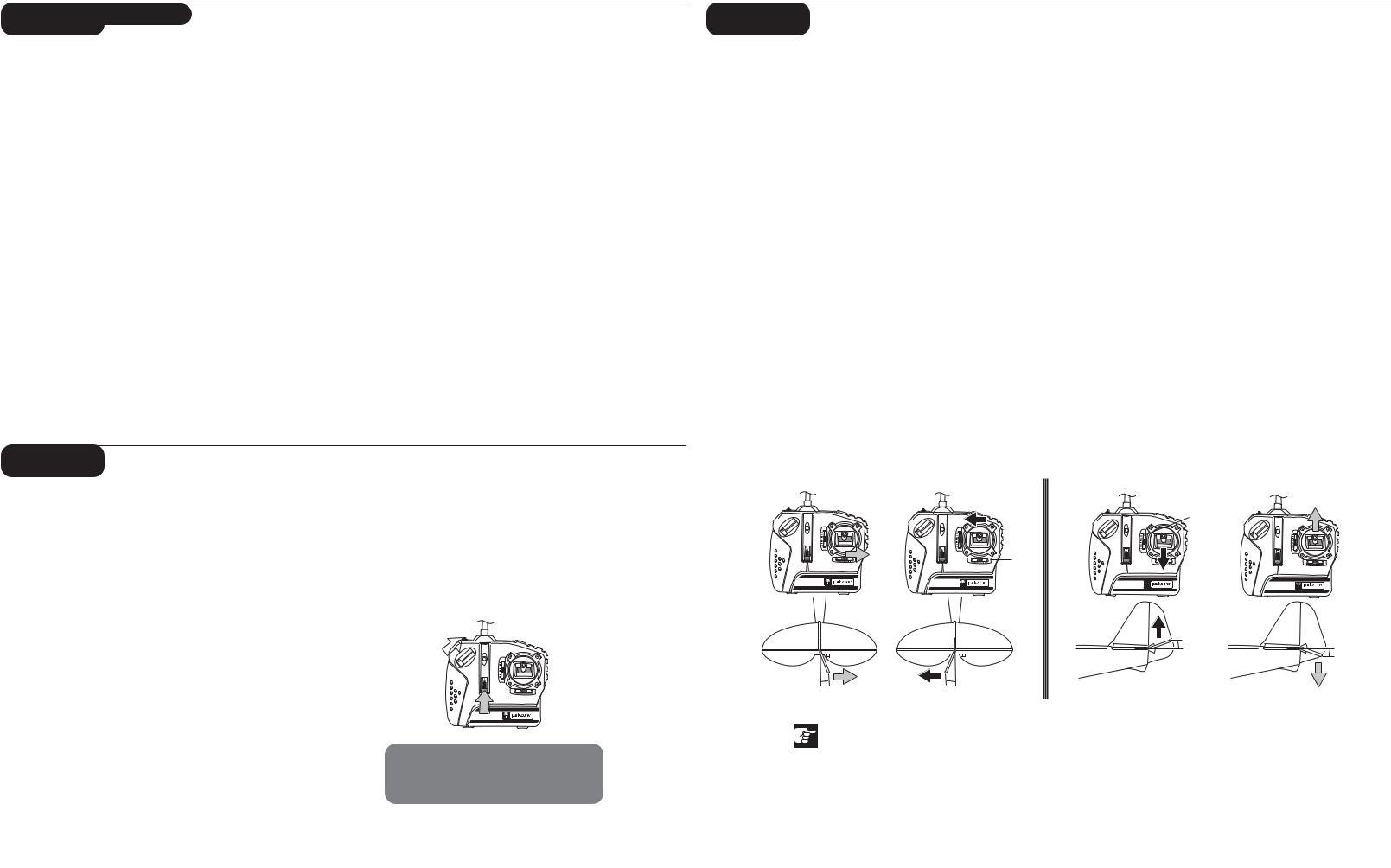
2.Move the stick from side to side. The rudder should move per your transmitter input.
Note: You will notice that when in the factory-set mode, a small amount of up elevator is also programmed in when the rudder is given input. This will help those pilots who are transitioning from two to three channels, as it will help keep the nose from falling when making turns.
3.Move the stick full forward. When this is done, the elevator control surface should move down (as shown).
4.Pull the stick back and the elevator control surface should move upward (as shown).
5.If your airplane is not responding correctly to the transmitter input, do not fly! Some correction is needed. Call the Horizon Product Support Group at 1-877-504-0233.
6.When the test is complete, be sure to disconnect the flight battery first, then turn off the transmitter. This should be done each time you turn off the airplane.
Note: It is very important to make sure that the control surfaces (rudder and elevator) are at 0 degrees when the transmitter control stick and trim levers are centered.
RUDDER |
ELEVATOR |
|
Elevator |
|
Trim |
|
Rudder |
|
Trim |
|
Up |
|
|
approx. |
|
|
1/4 in |
approx. |
|
(6mm) |
1/4 in |
|
|
(6mm) |
Right |
Left |
Down |
|
|
|
approx. |
approx. |
|
3/8 in (10mm) |
3/8 in (10mm) |
|
If rudder does not move as per control stick, do not fly.
5
 Loading...