

ParkZone PKZ4800 User Manual
ParkZone® products are distributed exclusively by
Horizon Hobby, Inc.
4105 Fieldstone Road
Champaign, IL 61822
© 2008 Horizon Hobby, Inc.
Super Decathlon BL
Instruction Manual
Horizon Hobby UK
Units 1-4, Ployters Road
Staple Tye
Harlow, Essex
CM187NS
United Kingdom
Horizon Hobby Deutschland GmbH
Otto Hahn Str. 9a
25337 Elmshorn
Germany
parkzone.com
13803
Futaba is a registered trademark of Futaba Denshi Kogyo Kabushiki Kaisha
Corporation of Japan.
Velcro
®
is a registered mark of Velcro Industries, B.V., Netherlands.
Charge-and-Fly™ Park Flyer
Wingspan: 35.4 in (900mm)
Overall Length: 25.3 in (640mm)
Weight: 16 oz (450 g)
Motor: PKZ 370-size outrunner brushless, 1500Kv
FM Radio System: ZX10 3 proportional channels
Battery: 7.4V 800mAh Li-Po
3
4
Super Decathlon BL
Step 2 – Installing the Transmitter Batteries
1. Insert 8 new AA batteries (supplied) into the
transmitter, observing proper polarity.
Introduction
Congratulations on your purchase of the ParkZone®
Super Decathlon BL. Your Super Decathlon BL has
come with everything to get you in the air—all in one box.
You will only need to attach the wing and landing gear, as
well as charge the battery prior to ight.
We at ParkZone are committed to giving you the most
enjoyable ight experience you can have. In order to
have a safe and successful ight, we ask that you do not
y until you have read these instructions thoroughly.
The Super Decathlon BL comes with a fully proportional
3-channel FM radio system, providing full control of
throttle, elevator and rudder. If you are not experienced
at ying one of HobbyZone’s 3-channel aircraft, or any
other 3-channel radio controlled aircraft, we recommend
that you do not y this aircraft. If you still choose to y,
you will need to seek the help of an experienced radio
control pilot during your rst several ights. Crash
damage is not covered under the warranty.
The ParkZone Super Decathlon BL is equipped with
the exclusive ZX10 radio system which utilizes 10-bit,
1024-step processing for high-delity control. It uses a
6-channel FM receiver with industry-standard 3-wire
servos.
The ZX10 system also features dual rates, allowing you
to y how you feel most comfortable. Low rate limits
the travel of the control surfaces and offers smooth and
relaxing ight. High rate allows for full control at all times
for those craving the maximum performance of their
aircraft.
2. Turn the power switch on to ensure the batteries
have been installed correctly. Once this is
conrmed, turn the transmitter off.
Step 3 – Installing the Landing Gear
1. Locate the landing gear within the packaging.
2. Slide one half of the landing gear into the
allotted slot in the fuselage until it locks into
place. Slide the other half of the landing gear into
the fuselage as you have done with the previous
one. Look into the fuselage to make sure the two
gear halves are pressed in snug against the
center of the landing gear support.
3. Make sure both parts of the landing gear are
secure and properly in place. They should feel
snug inside the fuselage when attached properly.
Step 1 – Charging the Aircraft Battery
This charger uses unique circuitry that ensures an
accurate charge every time and protects your Li-Po
batteries from the dangers of overcharging. This
charger continually monitors the battery and
automatically stops charging when the battery is fully
charged. The balance charger will help avoid damaging
Li-Po cells.
DC Li-Po Balancing Charger Features:
• Charges 2-cell lithium polymer battery packs
• LED charge status indicator
• LED cell balance indicator
• 12V outlet power cord
BATTERY CAPACITY
MAX. CHARGE RATE
CHARGE TIME
You must charge the included Li-Po battery pack with a
Li-Po specic charger only (such as the included
charger). Never leave the battery and charger unattended during the charge process. Failure to properly follow
the instructions could result in a re. When charging,
make certain the battery is on a heat-resistant surface. It
is recommended to charge the Li-Po battery immediately,
as it will be used in future assembly steps.
800mAh 7.4V 2S Li-Po
.8 amps
60 minutes
Charging the Aircraft Battery
1. The 12V DC 2S Li-Po balancing charger provides a
charge current of .8 amps. The typical charge time
for the included 7.4V 800mAh Li-Po is
approximately 40 minutes to 1 hour.
2. Locate the balancing charge lead on the
battery pack. Connect the battery pack to the
charger. Charge through the balance lead on the
battery pack.
3. Connect the charger to the 12V power outlet in
your automobile. Please note that some 12V
outlets require your vehicle to be running for the
outlet to be operational. It is not recommended to
charge batteries while the vehicle is in motion. The
LED will continually blink while the battery charges.
4. Charging is nished when the LED indicator
glows steadily.
Note: Damage to the charger and battery will occur if
you exceed the recommended maximum charge rate.
For charging outside of the vehicle, you may wish
to purchase a 12V DC extension with alligator leads
(HBZ6513). This will allow you to connect the charger
to a 12V battery or power supply.
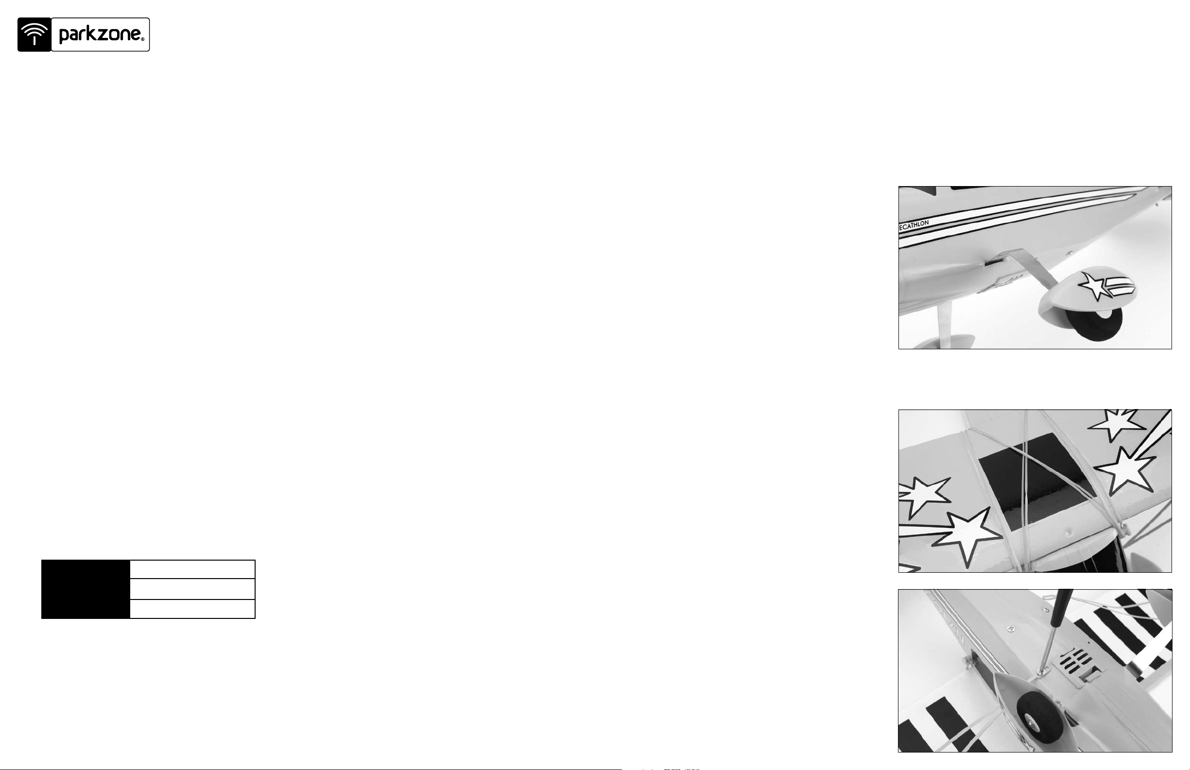
Step 4 – Attaching the Wing
1. Locate the wing and wing strut screws.
2. Place the wing on the top of the fuselage, making
certain it is centered properly. Attach the wing
with four rubber bands that are included. Stretch
two of the rubber bands from the front to the rear
attach points. Stretch the last two diagonally
across the middle to the attach points.
3. Attach the wing struts to the fuselage. Locate the
two small Phillips screws and attach the strut to
the fuselage as shown. Once the screw is
tightened into the fuselage, you can loosen it
slightly to allow the slack of the strut to be
adjusted as needed.
4. Make sure that prior to each ight the wing is
properly centered on the fuselage. If the wing
is not centered properly, it is impossible to have
correct ight.

5
6
Step 5 – Motor Test
Step 6 – Tail Control Test (continued)
1. Make sure the throttle slider is in the
OFF position.
2. Turn on the transmitter.
3. Remove the battery door from the bottom of
the fuselage.
4. Plug ight battery into the ESC inside of
the fuselage. The ESC has been preset for 2S
Li-Po low voltage cutoff.
5. Secure the battery inside the fuselage cavity and
replace the battery door.
6. Your Super Decathlon BL has a built-in
throttle-arming feature which needs to “see” the
throttle slider in the OFF position before it will
spin the propeller.
Caution: Make sure that you, as well as loose
objects and hair, are away from the propeller at
all times.
Grasp the rear of the fuselage with the nose of the
Super Decathlon facing away from you. Advance
the throttle forward and the propeller should spin
at a high speed. The throttle-arming feature will
need to be activated each time the battery is
plugged into the airplane.
7. When nished with the motor test, continue to the
Tail Control Test on the next page.
Note: It is important to always turn on the transmitter
prior to plugging in the flight battery. Plugging in the
flight battery first may cause undesired operation due
to interference, potentially resulting in damage to the
aircraft or personal injury.
Step 6 – Tail Control Test
Warning: Keep everything clear of the propeller before starting the control test in the event that you accidentally
turn on the motor.
4. Pull the stick back and the elevator control surface should move up.
5. If your airplane is not responding correctly to the transmitter input, do not fly. Some correction is needed.
Call the Horizon Support Team at 1-877-504-0233.
6. When the test is complete, be sure to disconnect the ight battery rst, then turn off the transmitter. This
should be done each time you turn off the airplane.
Note: It is very important to make sure that the control surfaces (rudder and elevator) are at 0 degrees when the
transmitter control stick and trim levers are centered.
1. Be certain that the throttle slider is in the OFF position. Make certain both trim levers are centered.
2. Move the stick from side to side. The rudder should move per your transmitter input.
3. Move the stick full forward. When this is done, the elevator control surface should move down.
Step 7 – Control Surface Adjustments
1. Any changes necessary to bring both the rudder
and elevator to neutral (0 degrees) when the
transmitter stick is centered should be possible
using the trim levers.
2. If you nd this is not the case, do not y until this
has been corrected.
3. If corrections are needed, you may have to adjust
the length of the pushrod by removing the clevis
from the control surface horn and turning the
plastic clevis as necessary. Prior to doing this,
make certain the trim levers and stick are centered.
If you have any questions regarding these
adjustments, please contact the Horizon Support Team
at 1-877-504-0233.
 Loading...