

ParkZone PKZ4475 User Manual [en, de, fr, it]
T-28 Trojan
Instruction Manual • Bedienungsanleitung • Manuel d’utilisation • Manuale di Istruzioni

ENEN
NOTICE
All instructions, warranties and other collateral documents are subject to change at the sole discretion of Horizon Hobby, Inc. For up-to-date product
literature, visit www.horizonhobby.com and click on the support tab for this product.
Meaning of Special Language:
The following terms are used throughout the product literature to indicate various levels of potential harm when operating this product:
NOTICE: Procedures, which if not properly followed, create a possibility of physical property damage AND little or no possibility of injury.
CAUTION: Procedures, which if not properly followed, create the probability of physical property damage AND a possibility of serious injury.
WARNING: Procedures, which if not properly followed, create the probability of property damage, collateral damage, and serious injury OR create a high
probability of superfi cial injury.
WARNING: Read the ENTIRE instruction manual to become familiar with the features of the product before operating. Failure to operate the product
correctly can result in damage to the product, personal property and cause serious injury.
This is a sophisticated hobby product. It must be operated with caution and common sense and requires some basic mechanical ability. Failure to operate this Product in a safe and responsible manner could result in injury or damage to the product or other property. This product is not intended for use
by children without direct adult supervision. Do not attempt disassembly, use with incompatible components or augment product in any way without the
approval of Horizon Hobby, Inc. This manual contains instructions for safety, operation and maintenance. It is essential to read and follow all the instructions
and warnings in the manual, prior to assembly, setup or use, in order to operate correctly and avoid damage or serious injury.
Additional Safety Precautions and Warnings
As the user of this product, you are solely responsible for operating in a manner that does not endanger yourself and others or result in damage to the product or
the property of others.
Age Recommendation: Not for children under 14 years. This is not a toy.
• Always keep a safe distance in all directions around your model to avoid collisions or injury. This model is controlled by a radio signal subject to interference
from many sources outside your control. Interference can cause momentary loss of control
• Always operate your model in open spaces away from full-size vehicles, traffi c and people.
• Always carefully follow the directions and warnings for this and any optional support equipment (chargers, rechargeable battery packs, etc.).
• Always keep all chemicals, small parts and anything electrical out of the reach of children.
• Always avoid water exposure to all equipment not specifi cally designed and protected for this purpose. Moisture causes damage to electronics.
• Never place any portion of the model in your mouth as it could cause serious injury or even death.
• Never operate your model with low transmitter batteries.
Battery Warnings
The Battery Charger included with your aircraft is designed to safely charge the Li-Po battery.
CAUTION: All instructions and warnings must be followed exactly. Mishandling of Li-Po batteries can result in a fi re, personal injury, and/or property damage.
• By handling, charging or using the included Li-Po battery, you assume all
risks associated with lithium batteries.
• If at any time the battery begins to balloon or swell, discontinue use imme-
diately. If charging or discharging, discontinue and disconnect. Continuing
to use, charge or discharge a battery that is ballooning or swelling can
result in fi re.
• Always store the battery at room temperature in a dry area for best results.
• Always transport or temporarily store the battery in a temperature range of
40–120º F. Do not store battery or model in a car or direct sunlight. If stored
in a hot car, the battery can be damaged or even catch fi re.
• NEVER USE A Ni-Cd OR Ni-MH CHARGER. Failure to charge the battery with
a compatible charger may cause fi re resulting in personal injury and/or
property damage.
• Never discharge Li-Po cells to below 3V under load.
• Never cover warning labels with hook and loop strips.
• Never leave charging batteries unattended.
• Never charge batteries outside safe temperature range.
• Never charge damaged batteries.
2
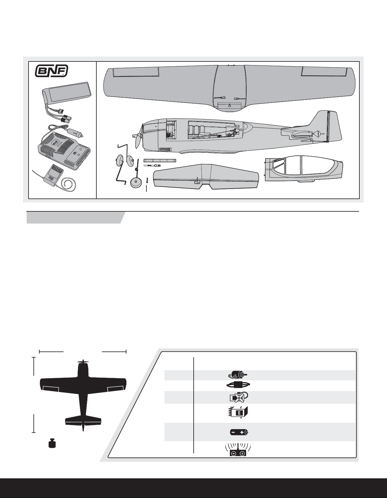
Smooth, predictable response and plenty of power; these are the hallmarks of a great sport fl ying experience and a big reason why the ParkZone® T-28 Trojan
is one of the most popular parkfl yers of all time. Please take some time to read this manual. In addition to instructions for fi nal assembly, you’ll fi nd handy setup
tips, important battery charging precautions and a helpful trouble shooting guide. It’s all here to make sure your fi rst fl ight, and every one after, is as successful
as can be.
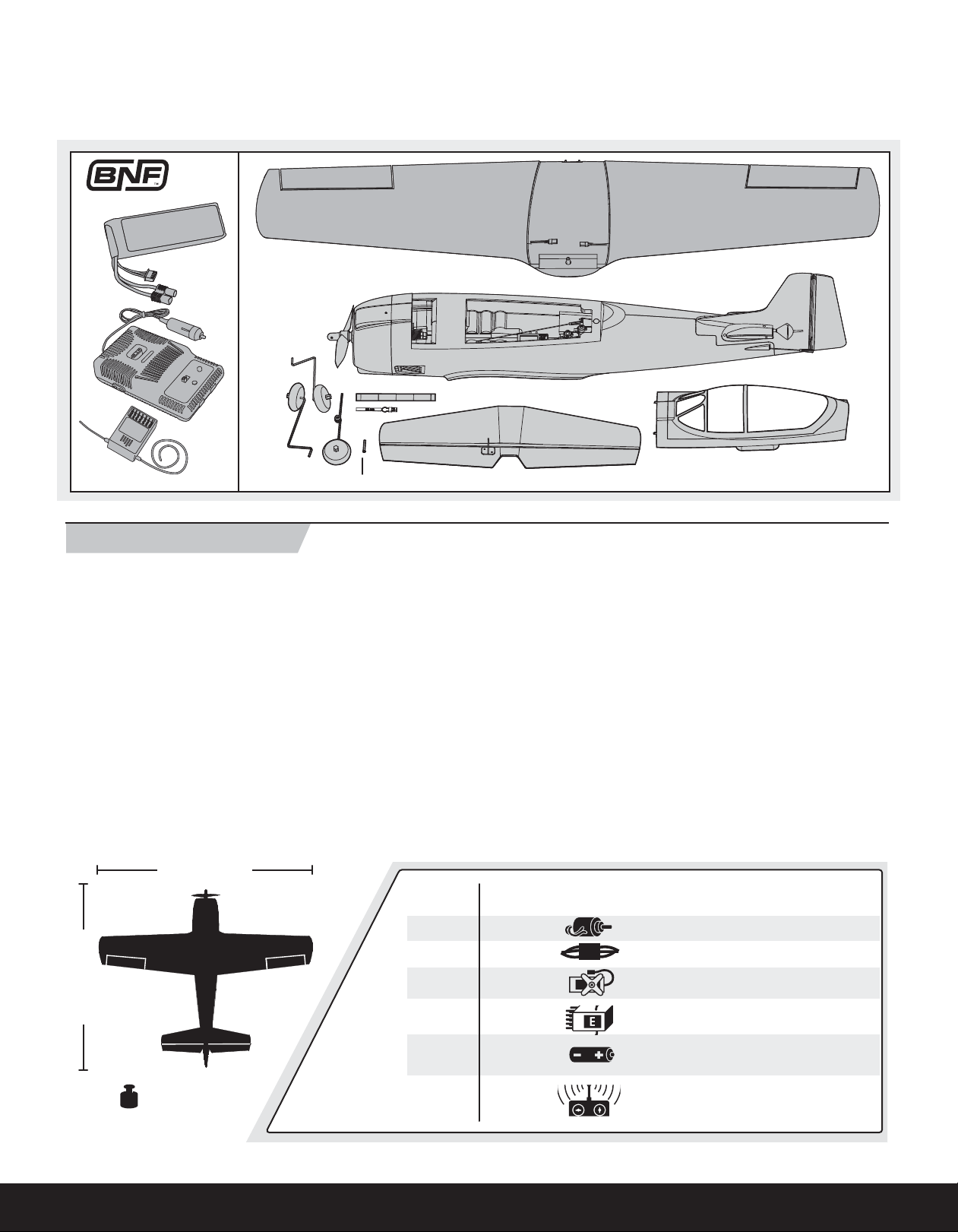
Includes:
3 X 25mm
ENEN
Table of Contents
Battery Warnings .............................................................................. 2
Charging the Flight Battery ............................................................... 4
Low Voltage Cutoff (LVC) ................................................................... 4
Transmitter and Receiver Binding ...................................................... 5
Installing Battery ............................................................................... 5
Before Flight ..................................................................................... 6
Installing a Receiver .......................................................................... 6
Battery Selection and Installation ...................................................... 6
Installing Wing .................................................................................. 6
Installing Landing Gear ..................................................................... 7
Installing Horizontal Tail .................................................................... 7
Installing Clevises on Control Horns and Control Centering ................ 8
Factory Settings ................................................................................ 8
Center of Gravity (CG) ....................................................................... 8
Control Direction Test ........................................................................ 9
44 in (1120mm)
Bind-N-Fly
Aircraft
Installed
Installed
Dual Rates ...................................................................................... 10
Service of Power Components ........................................................ 10
Nose Gear Service .......................................................................... 11
Flying Tips and Repairs ................................................................... 12
First Flight Preparation .................................................................... 12
Maintenance After Flying ................................................................ 12
AMA National Model Aircraft Safety Code ........................................ 13
Troubleshooting Guide .................................................................... 14
Limited Warranty ............................................................................ 15
Contact Information ........................................................................ 16
Compliance Information for the European Union .............................. 16
Replacement Parts ......................................................................... 59
Optional Parts ................................................................................. 60
Parts Contact Information ............................................................... 61
®
Plug-N-Play®
Aircraft
Installed
Installed
480 BL outrunner; 960Kv
EFL 30A Pro SB brushless ESC
36 in (915mm)
30 oz (875 g)
Installed
Installed
Included
Needed to
Complete
Installed
Needed to
Complete
Needed to
Complete
Needed to
Complete
To register your product online, visit www.parkzone.com
(4) Servos
Recommended Receiver: Spektrum
®
or DSMX
Battery: 3S 1800-2200mAh Li-Po
Battery Charger: 300mA-2.0A
2–3 cell Li-Po battery charger
Recommended Transmitter:
Full-Range 2.4GHz with Spektrum
DSM2™/DSMX® technology.
full-range or parkfl yer sport receiver
™
™
DSM2™
3

ENEN
Charging the Flight Battery
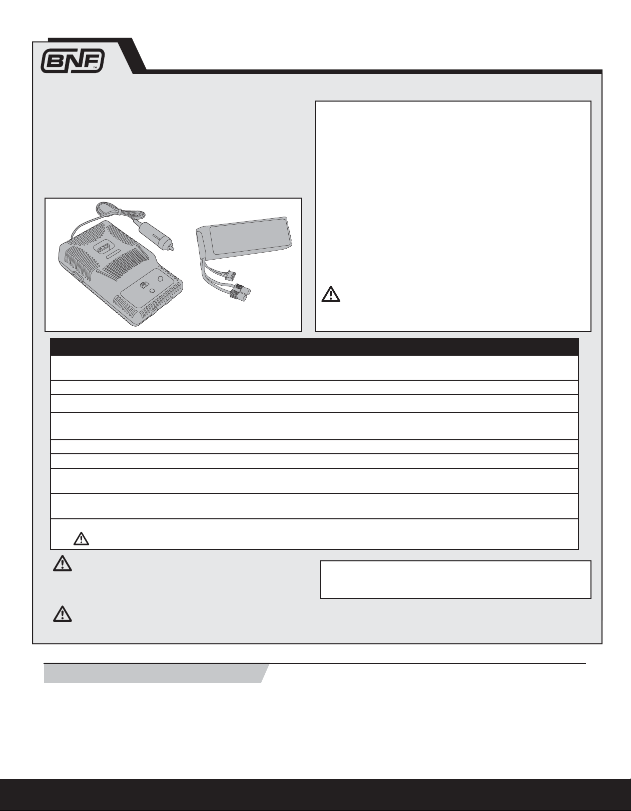
Your T-28 comes with a DC balancing charger and 3S Li-Po battery. You should
only charge your battery with the included charger. Never leave the battery and
charger unattended during the charge process. Failure to follow the instructions
properly could result in a fi re. When charging, make sure the battery is on a
heat-resistant surface. Charge the fl ight battery while assembling the aircraft.
Install the fully charged battery to perform control tests and binding.
DC Li-Po Balancing Charger Features
• Charges 2- to 3-cell lithium polymer battery packs
• Variable charge rates from 300mAh to 2-amp
• Simple single push-button operation
• LED charge status indicator
• LED cell balance indicator
• Audible beeper indicates power and charge status
• 12V accessory outlet input cord
Specifi cations
• Input power: 12V DC, 3-amp
• Charges 2- to 3-cell Li-Po packs with minimum
capacity of 300mAh
3S 11.1V 1800mAh Li-Po Battery Pack (PKZ1031)
The ParkZone
you to safely charge your battery pack when used with the included ParkZone
Li-Po balancing charger.
of your charger prior to charging.
®
3S Li-Po battery pack features a balancing lead that allows
CAUTION: The balance connector must be inserted into the correct port
The Battery Charging Process
1. Charge only batteries that are cool to the touch and are not damaged. Look at the battery to ensure it is not damaged e.g., swollen, bent, broken or
punctured.
2. Attach the input cord of the charger to the appropriate power supply (12V accessory outlet).
3. When the Li-Po charger has been correctly powered up, there will be an approximate 3-second delay, then an audible “beep” and the green (ready)
LED will fl ash.
4. Turn the control on the Amps selector so the arrow points to the charging rate required for the battery (the T-28’s included 1800mAh Li-Po battery will
charge at 2.0 amps). DO NOT change the charge rate once the battery begins charging.
5. Move the cell selector switch to 3-cell for your battery.
6. Connect the Balancing Lead of the battery to the 3-cell (it has 4 pins) charger port.
7. Press the Start button to begin charging the battery. The green and red LEDs may fl ash during the charging process when the charger is balancing
cells. Balancing prolongs the life of the battery.
8. When the battery is fully charged, there will be an audible beep for about 3 seconds and the green LED will shine continuously. Attempting to charge
an over-discharged battery will cause the charger to repeatedly fl ash and beep, indicating an error has occurred.
9. Always unplug the battery from the charger immediately upon completion of charging.
CAUTION: Overcharging a battery can cause a fi re.
CAUTION: Only use a charger specifi cally designed to charge a Li-Po
battery. Failure to do so could result in fi re causing injury or property
damage.
CAUTION: Never exceed the recommended charge rate.
Low Voltage Cutoff (LVC)
When a Li-Po battery is discharged below 3V per cell, it will not hold a charge.
The ESC protects the fl ight battery from over-discharge using Low Voltage
Cutoff (LVC). Before the battery charge decreases too much, LVC removes
power supplied to the motor. Power to the motor pulses, showing that some
battery power is reserved for fl ight control and safe landing.
4
NOTICE: If using a battery other than the included Li-Po battery, refer to your
battery manufacturer’s instructions for charging.
When the motor pulses, land the aircraft immediately and recharge the
fl ight battery.
Disconnect and remove the Li-Po battery from the aircraft after use to prevent
trickle discharge. Fully charge your Li-Po battery before storing it. During
storage, make sure battery charge does not fall below 3V per cell.
Transmitter and Receiver Binding
BIN
D
/DATA
THR
O
AILE
ELEV
RUDD
GEAR
AUX
1
2.4GHz DSM® TECHNOLOGY
6CH SPORT RECEIVER 2048
Binding is the process of programming the receiver of the control unit to recognize the GUID (Globally Unique Identifi er) code of a single specifi c transmitter. You
need to ‘bind’ your chosen Spektrum DSM2/DSMX technology equipped aircraft transmitter to the receiver for proper operation.
Please visit www.bindnfl y.com for a complete list of compatible transmitters.
NOTICE: When using a Futaba transmitter with a Spektrum DSM® module, you must reverse the
throttle channel.
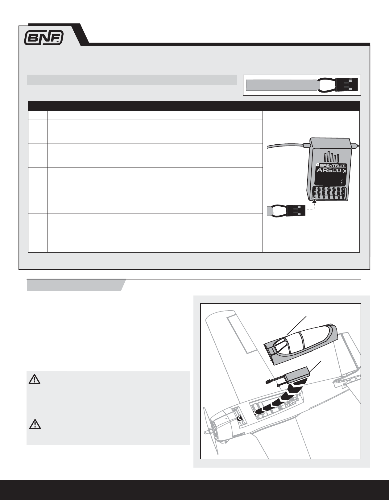
Binding Procedure Reference Table
1. Read transmitter instructions for binding to a receiver (location of transmitter’s Bind control).
2. Make sure the transmitter is powered off.
3. Move the transmitter controls to neutral (fl ight controls: rudder, elevators and ailerons) or to low
positions (throttle, throttle trim).*
4. Install a bind plug in the receiver bind port.
5. Connect the fl ight battery to the ESC. The ESC will produce a series of sounds. One long tone,
then three short tones confi rm that the LVC is set for the ESC.
6. The receiver LED will begin to fl ash rapidly.
7. Power on the transmitter while holding the transmitter bind button or switch. Refer to your
transmitter’s manual for binding button or switch instructions.
8. When the receiver binds to the transmitter, the light on the receiver will turn solid and the ESC
will produce a series of three ascending tones. The tones will indicate the ESC is armed, provided the throttle stick and throttle trim are low enough to trigger arming.
9. Remove the bind plug from the bind port.
10. Safely store the bind plug (some owners attach the bind plug to their transmitter using two-part
loops and clips).
11. The receiver should retain the binding instructions received from the transmitter until another
binding is done.
* The throttle will not arm if the transmitter’s throttle control is not put at the lowest position. If you encounter problems, follow binding instructions and refer
to the transmitter troubleshooting guide for other instructions. If needed, contact the appropriate Horizon Product Support offi ce.
BIND PLUG
ENEN
Installing the Battery
1. Carefully lift the back of the canopy (A) and pull the canopy pins from the
holes in the fuselage to remove the canopy.
2. Put the blue battery connector toward the front of the airplane and install
the fl ight battery (B) all the way to the front of the battery compartment.
3. If binding the aircraft receiver to the transmitter, refer to the transmitter
manual’s binding instructions. If the aircraft is already bound to the transmitter, remember to always power on the transmitter before connecting
the fl ight battery to the ESC connector in the aircraft.
4. Install the canopy on the fuselage. Make sure the magnets on the canopy
and fuselage meet.
CAUTION: Always disconnect the Li-Po battery from the aircraft
receiver when not fl ying to avoid over-discharging the battery. Batteries
discharged to a voltage lower than the lowest approved voltage may become
damaged, resulting in loss of performance and potential fi re when batteries
are charged.
CAUTION: Always keep hands away from propeller. When armed, the
motor will turn the propeller in response to any throttle movement.
A
B
5
EN
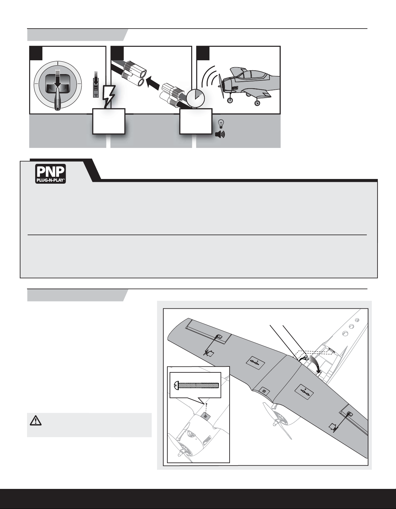
Before Flight
1 2 3
• Lower throttle and
throttle trim to
lowest settings.
Power on
Transmitter
• Connect battery
to ESC.
Installing a Receiver
1. Remove the wing to install a receiver.
2. Install your parkfl yer or full-range receiver in the fuselage using hook and
loop tape or double-sided servo tape.
3. Attach the elevator and rudder servo connectors to the appropriate channels of the receiver.
Battery Selection and Installation
1. The required battery is a 1800–2200mAh 11.1V Li-Po battery. We recommend the ParkZone
2. If using another battery, the battery must be at least a 1800–2200 mAh
battery.
®
1800mAh (PKZ1031) or the 2200mAh (PKZ1029).
Installing the Wing
Wait 5
seconds
4. Attach the aileron Y-harness to the aileron channel of the receiver.
5. Attach the ESC connector to the throttle channel of the receiver.
3. Your battery should be approximately the same capacity, dimensions and
weight as the ParkZone Li-Po battery to fi t in the fuselage without changing
the center of gravity.
Continuous LED
Series of tones
1. Remove the canopy from the fuselage.
2. Turn the wing and fuselage so their bottom sides
face up.
3. Place the wing’s aileron servo connectors (A) into the
rectangular hole in the fuselage.
4. Slide the two guide pins (B) of the wing into the two
holes in the fuselage.
5. Align and attach the wing to the fuselage using
a screw (C).
6. Inside the fuselage, connect both aileron servo
connectors to the aileron Y-harness. There is no
difference between the two connections on a Yharness. Left and right servo connectors do not have
to be connected to a particular side of a Y-harness.
7. When needed, disassemble in reverse order.
CAUTION: DO NOT crush or otherwise damage
wiring when attaching the wing to the fuselage.
NOTICE: Use of CA (cyanocrylate adhesive) accelerant on
your model can damage paint. DO NOT handle the model
until the accelerant fully dries.
6
C
3 X 25mm
B
A
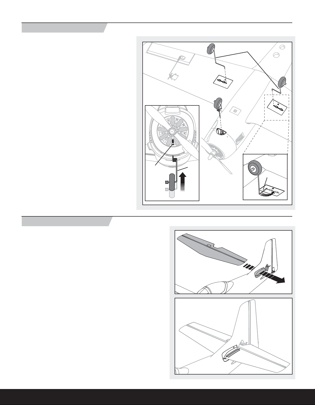
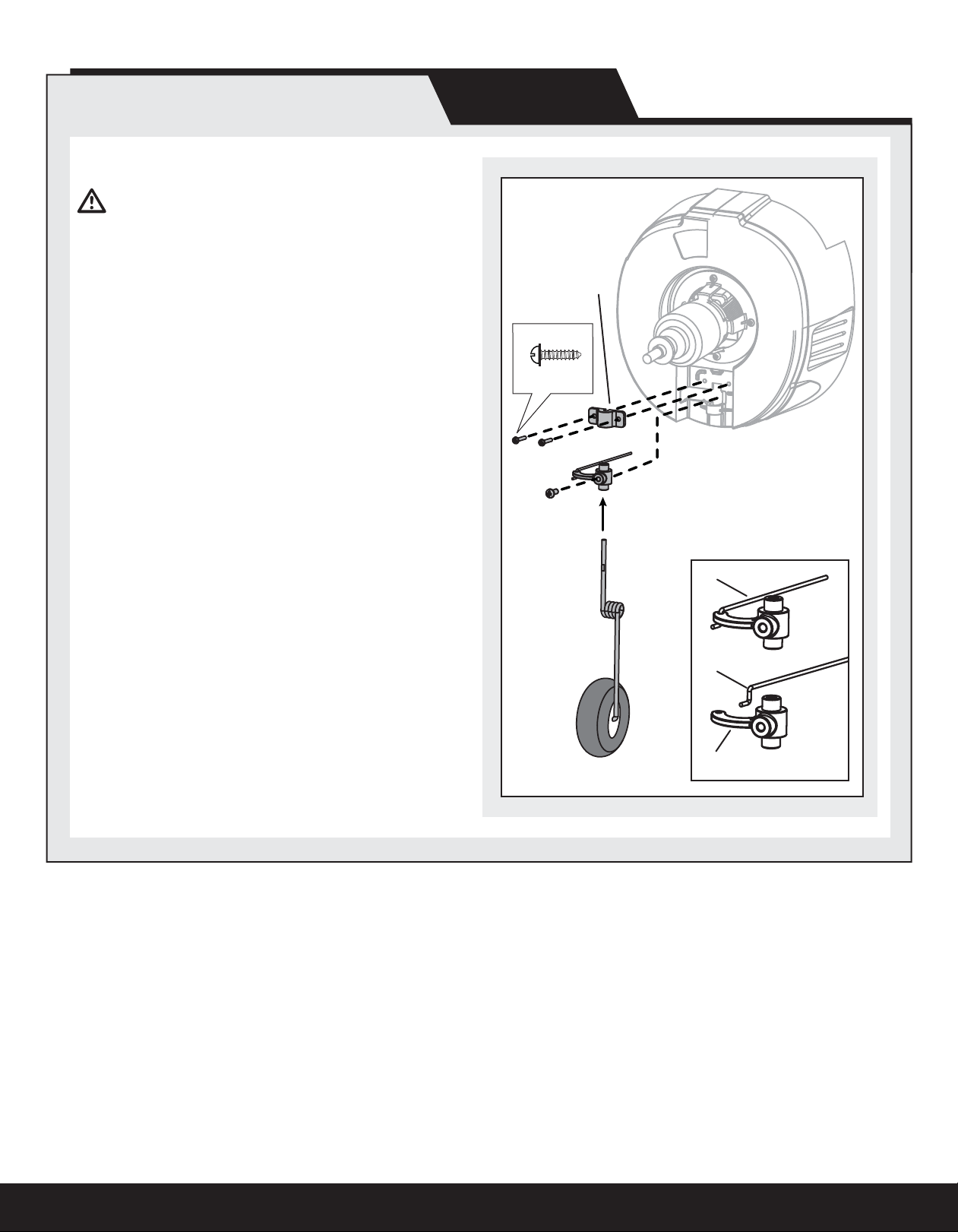
Installing the Landing Gear
Installation
1. Turn the model so the bottom of the wing faces up.
2. Install the main landing gear by inserting the main gear
struts (A) into the corresponding gear plate hole located on
each wing.
3. Carefully turn each strut in the gear plate until the horizontal
section (B) of the strut gently snaps into place.
4. Loosen the nose gear screw (C) in the nose gear arm before
installing the nose gear strut (D). The screw may be fully
installed at the factory, so loosen the screw enough to ensure
the screw does not block the strut. A hole in the cowling
allows a screwdriver to be used to turn the screw on the nose
gear arm.
If more maneuvering space is needed, remove the propeller
and cowling from the model before installing the nose gear.
(As shown in the “Service of Power Components” section
of this manual.)
5. Install the nose gear strut so the fl at surface of the strut faces
forward. The coil in the nose gear strut should face the rear
of the airplane. Fully insert the nose gear strut into the nose
gear arm. When inserted, the top of the strut will touch the
upper portion of the fi rewall.
6. Fully tighten the nose gear screw against the fl at surface of
the nose gear strut.
7. When needed, disassemble in reverse order.
EN
A
Always ensure the steering linkage clevis on the rudder servo
arm is correctly adjusted so the model steers straight when the
rudder control is at neutral.
Installing the Horizontal Tail
1. Place the model on its landing gear.
2. Turn the horizontal tail so the control horn faces down.
3. Slide the horizontal tail in the horizontal tail mount until it is centered
perpendicular to the vertical tail.
4. Apply four pieces of tape on the fuselage mounts and the top and bottom of
the horizontal tail.
5. Attach the clevis to the elevator control horn (see instructions for
clevis connection).
6. When needed, disassemble in reverse order.
C
D
B
7
EN
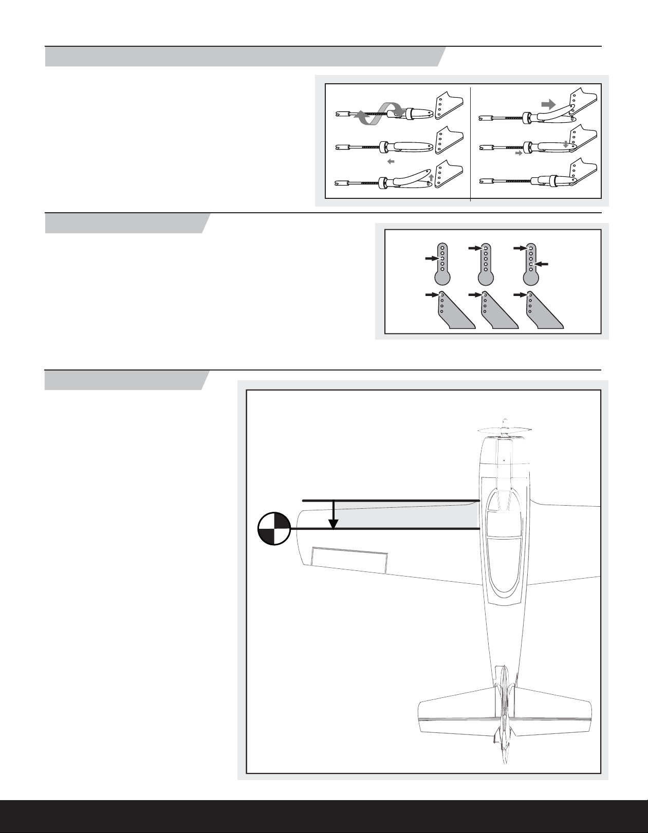
Installing Clevises on Control Horns and Control Centering
Tip: Turn the clevis clockwise or counterclockwise on the linkage.
• Pull the tube from the clevis to the linkage.
• Carefully spread the clevis and put the clevis pin into the desired hole in
the control horn.
• Move the tube to tighten the clevis onto the control horn.
After binding a transmitter to the model receiver, set all trims and sub-trims
to 0, then adjust the clevises to center the control surfaces.
1.
2.
3.
Factory Settings
Fly the model at factory settings before making any changes. For pilots who
wish for more control throw, adjust the position of the control linkages on
the servo arms and control horns for increased travel.
Arms
Horns
Elevator
4.
5.
6.
Ailerons
Rudder
Nose Gear
Center of Gravity (CG)
Place the battery all the way forward in the fuselage
and hold the battery in place using a hook and loop
strap. It is easiest to balance the T-28 with the
aircraft inverted.
63.5mm
(2.5 inches) from the leading edge
of the wing at the fuselage.
8
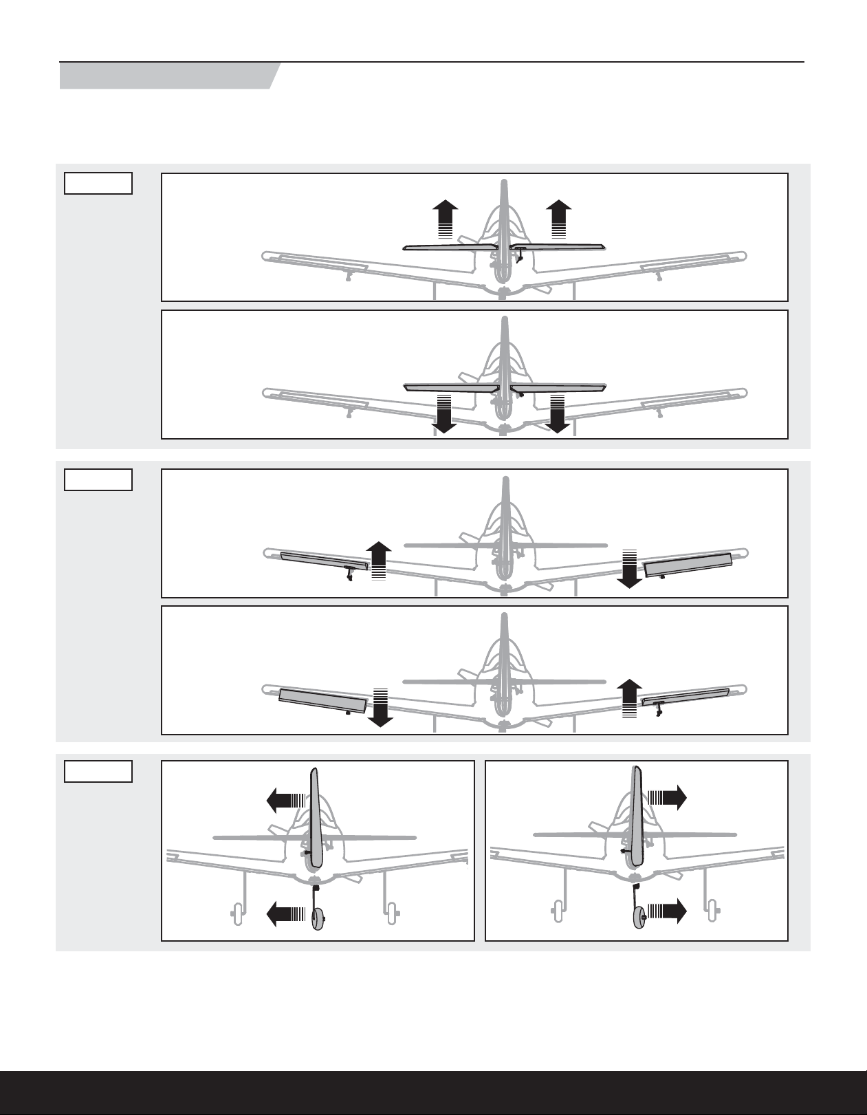
Control Direction Test
Bind your aircraft and transmitter before performing these tests. Move the controls on the transmitter to ensure the aircraft control surfaces move correctly.
After doing the Control Test, correctly set the failsafe. Make sure the transmitter controls are at neutral and the throttle and throttle trim are in the low position,
then rebind the model to your transmitter. If the receiver loses its link to the transmitter, the failsafe automatically moves the controls and throttle settings to
those made at binding.
EN
EN
Elevator
Aileron
Up Elevator
Down Elevator
Stick
Left
Rudder
Stick
Right
Stick
Left
Stick
Right
9
EN
Dual Rates
We recommend using a DSM2/DSMX aircraft transmitter capable of dual rates.
Adjust according to individual preferences after initial fl ight.
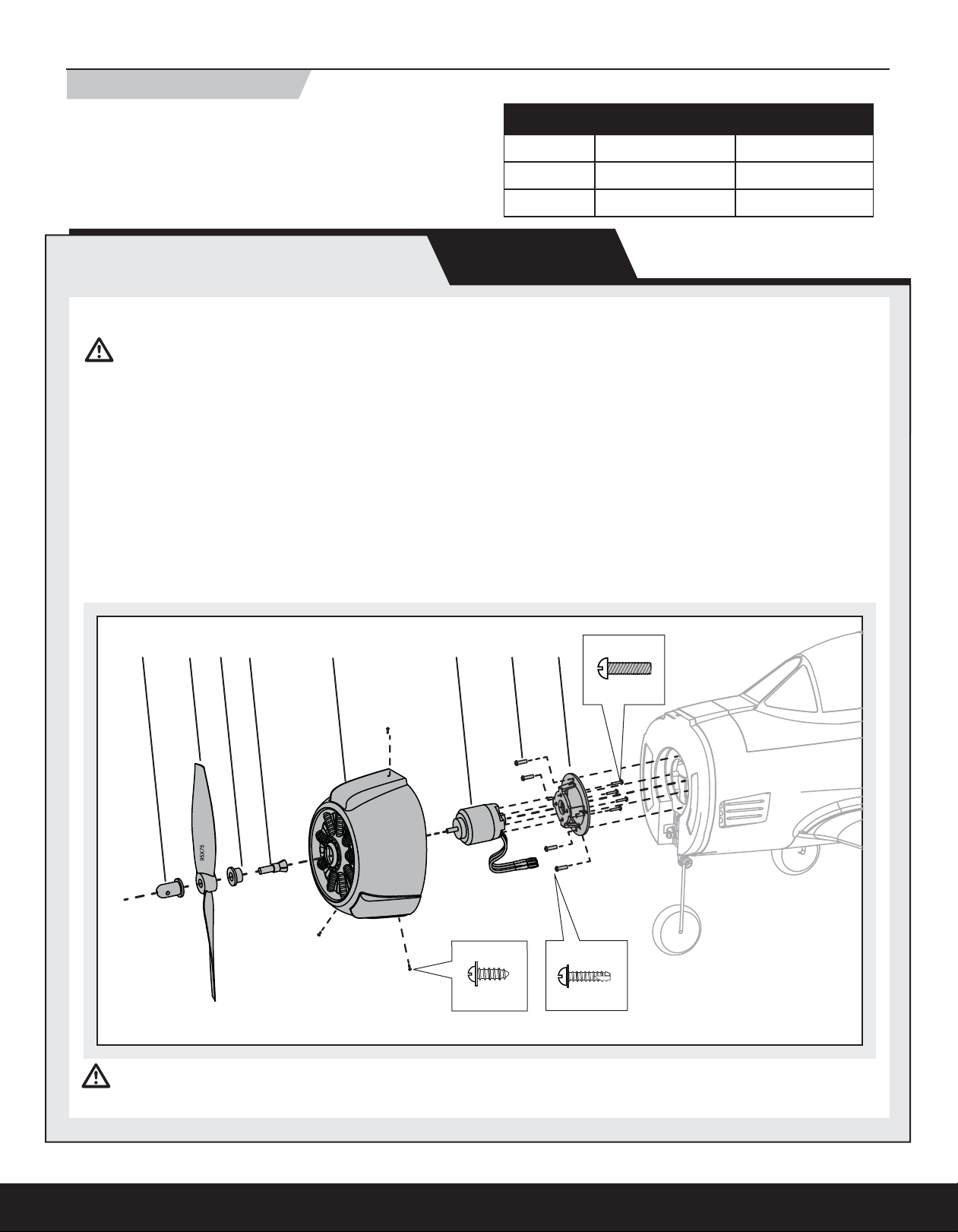
Service of Power Components
Disassembly
CAUTION: DO NOT handle the motor or ESC while the fl ight battery is
connected to the ESC. Personal injury could result.
1. Use a tool to remove the spinner nut (A) from the collet (B).
2. Remove the propeller (C), backplate (D) and collet from the motor shaft.
3. Remove three screws (E) from the cowling (F).
4. Carefully remove the cowling from the fuselage. Paint may keep the
cowling attached to the fuselage.
5. Remove four screws (G) from the motor mount (H) and fuselage.
6. Disconnect the motor wires from the ESC wires.
7. Remove four screws (I) and motor (J) from the motor mount. Keep
the rubber washers attached to the motor mount when removing the
screws and motor from the motor mount.
High Rate Low Rate
Aileron 13mm up/down 9.5mm up/down
Elevator 16mm up/down 13mm up/down
Rudder 22mm left/right 16mm left/right
MAINTENANCE
Assembly
1. Assemble in reverse order. Correctly align the colors of the motor wires
with the wire colors of the ESC.
NOTICE: Make sure the propeller side with the numbers for diameter and
pitch (9.5 x 7.5) faces out from the backplate. A tool is required to tighten
the spinner nut on the collet.
A
CDB F HGJ
E
2X5mm (3)
CAUTION: Always disconnect the fl ight battery from the model before removing the propeller.
1.5X10mm (4)
I
3X10mm (4)
G
Not all wiring shown.
10
EN
Nose Gear Service
Hard landings may damage the nose gear. Replace damaged parts as needed.
CAUTION: DO NOT handle the propeller while the fl ight battery is
connected to the ESC. Personal injury could result.
1. Remove the canopy from the model.
2. Disconnect the fl ight battery from the model.
3. Disconnect the steering clevis from the rudder servo arm.
4. Remove the propeller and cowling from the model. (As shown in the
“Service of Power Components” section of this manual.)
5. Loosen the nose gear screw and remove the strut.
6. Remove the two screws (A) and steering arm retainer (B) (PKZ4408,
retainer with steering arm) from the fi rewall.
7. Pull the steering linkage (C) forward and remove the Z-bend end (D) of
the linkage from the steering arm (E) (PKZ4408, including steering arm
retainer).
8. Reinstall the steering arm on the Z-bend end of the linkage.
9. Install the steering arm in the fi rewall using the steering arm retainer
and two screws.
10. Connect the linkage clevis to the rudder servo arm.
11. Install the strut using the screws.
12. Reinstall the cowling, propeller and canopy on the model.
MAINTENANCE
B
A
2.5X12mm (2)
NOTICE: Always make sure the steering linkage clevis is adjusted correctly to
ensure the model steers straight when the rudder control is at neutral.
C
D
E
11
EN
Prefl ight Checklist
Before Flying Check List
1. Charge fl ight battery.
2. Install fl ight battery in aircraft (once it has been fully charged).
3. Bind aircraft to transmitter.
4. Make sure linkages move freely.
5. Perform Control Direction Test with transmitter.
Flying Tips and Repairs
Range Check your Radio System
After fi nal assembly, range check the radio system with the T-28. Refer to your
specifi c transmitter instruction manual for range test information.
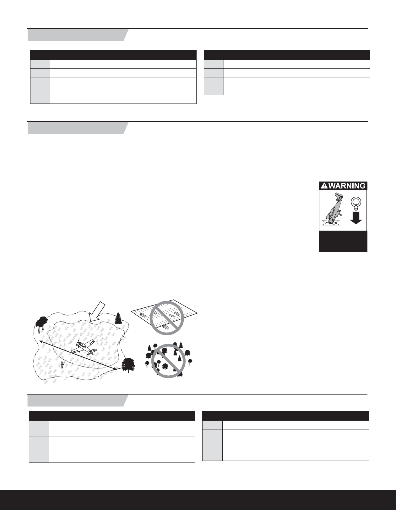
Flying
Always choose a wide-open space for fl ying your ParkZone T-28. It is ideal
that you fl y at a sanctioned fl ying fi eld. If you are not fl ying at an approved site,
always avoid fl ying near houses, trees, wires and buildings. You should also
be careful to avoid fl ying in areas where there are many people, such as busy
parks, schoolyards or soccer fi elds. Consult local laws and ordinances before
choosing a location to fl y your aircraft.
Although this model is not intended for pilots to teach themselves to fl y, the
T-28 has proven to be a popular model for fi rst-time RC pilots. For new pilots,
we recommend learning to fl y this model using two compatible Spektrum
transmitters connected in Trainer mode under the guidance of an experienced
pilot. You may want to explore the use of a Spektrum transmitter with a simulator, such as the Phoenix R/C Pro Flight Simulator 3.0 (RTM3000). Use the
transmitter with the simulator to practice and experiment without damaging
your model.
Before Flying Check List
6. Adjust fl ight controls and transmitter.
7. Perform a radio system Range Check.
8. Find a safe and open area.
9. Plan fl ight for fl ying fi eld conditions.
Landing
For your fi rst fl ights, set your transmitter timer or a stopwatch to 7 minutes.
Adjust your timer for longer or shorter fl ights once you have fl own the model.
When the motor pulses, land the aircraft immediately and recharge the
fl ight battery. It is not recommended to continuously fl y the battery to LVC.
To land the T-28, fl y the airplane down to about a foot
above the ground. Reduce power and add back pressure on the elevator to fl are the airplane. Touch down
with the main wheels fi rst by holding the nosewheel
off the ground. Avoid holding too much elevator after
touchdown to prevent the plane from becoming
airborne again. Gently steer with the rudder until the
plane has slowed. Avoid sharp turns on the ground
until the plane has slowed enough to prevent scraping
the wing tips.
NOTICE: When fi nished fl ying, never keep the airplane
in the sun. Do not store the aircraft in a hot, enclosed area such as a car. Doing
so can damage the foam.
Always
decrease throttle at
propeller strike.
PhoenixRC and the PhoenixRC logo are registered trademarks of Runtime Games Ltd.
Fly in this area
(upwind of pilot)
600
feet (182.8 m)
Stand here
Post Flight Checklist
After Flying Check List
1. Disconnect fl ight battery from ESC (Required for Safety and
battery life).
2. Power off transmitter.
3. Remove fl ight battery from aircraft.
4. Recharge fl ight battery.
Repairs
Thanks to the Z-Foam™ construction of the T-28, repairs to most of the foam
can be made using virtually any adhesive (hot glue, regular CA (cyanocrylate
adhesive), epoxy, etc). The horizontal tail is not made of the same material, so
use only foam-compatible CA on the horizontal tail.
NOTICE: Use of CA accelerant on your model can damage paint. DO NOT
handle the model until the accelerant fully dries.
When parts are not repairable, see the Replacement Parts List for ordering by
item number.
After Flying Check List
5. Repair or replace all damaged parts.
6. Store fl ight battery apart from aircraft and monitor the battery
charge.
7. Make note of fl ight conditions and fl ight plan results,
planning for future fl ights.
12

AMA National Model Aircraft Safety Code
EN
Effective January 1, 2011
A. GENERAL
A model aircraft is a non-human-carrying aircraft capable of sustained fl ight
in the atmosphere. It may not exceed limitations of this code and is intended
exclusively for sport, recreation and/or competition. All model fl ights must
be conducted in accordance with this safety code and any additional rules
specifi c to the fl ying site.
1. Model aircraft will not be fl own:
(a) In a careless or reckless manner.
(b) At a location where model aircraft activities are prohibited.
2. Model aircraft pilots will:
(a) Yield the right of way to all man carrying aircraft.
(b) See and avoid all aircraft and a spotter must be used when appropriate.
(AMA Document #540-D-See and Avoid Guidance.)
(c) Not fl y higher than approximately 400 feet above ground level within
three (3) miles of an airport, without notifying the airport operator.
(d) Not interfere with operations and traffi c patterns at any airport, heliport
or seaplane base except where there is a mixed use agreement.
(e) Not exceed a takeoff weight, including fuel, of 55 pounds unless in
compliance with the AMA Large Model Aircraft program. (AMA
Document 520-A)
(f) Ensure the aircraft is identifi ed with the name and address or AMA
number of the owner on the inside or affi xed to the outside of the model
aircraft. (This does not apply to model aircraft fl own indoors).
(g) Not operate aircraft with metal-blade propellers or with gaseous boosts
except for helicopters operated under the provisions of AMA Document
#555.
(h) Not operate model aircraft while under the infl uence of alcohol or while
using any drug which could adversely affect the pilot’s ability to safely
control the model.
(i) Not operate model aircraft carrying pyrotechnic devices which explode
or burn, or any device which propels a projectile or drops any object
that creates a hazard to persons or property.
Exceptions:
• Free Flight fuses or devices that burn producing smoke and are
securely attached to the model aircraft during fl ight.
• Rocket motors (using solid propellant) up to a G-series size may
be used provided they remain attached to the model during fl ight.
Model rockets may be fl own in accordance with the National
Model Rocketry Safety Code but may not be launched from
model aircraft.
• Offi cially designated AMA Air Show Teams (AST) are authorized to
use devices and practices as defi ned within the Team AMA
Program Document (AMA Document #718).
(j) Not operate a turbine-powered aircraft, unless in compliance with the
AMA turbine regulations. (AMA Document #510-A).
3. Model aircraft will not be fl own in AMA sanctioned events, air shows or
model demonstrations unless:
(a) The aircraft, control system and pilot skills have successfully
demonstrated all maneuvers intended or anticipated prior to the
specifi c event.
(b) An inexperienced pilot is assisted by an experienced pilot.
4. When and where required by rule, helmets must be properly worn and
fastened. They must be OSHA, DOT, ANSI, SNELL or NOCSAE approved or
comply with comparable standards.
B. RADIO CONTROL
1. All pilots shall avoid fl ying directly over unprotected people, vessels,
vehicles or structures and shall avoid endangerment of life and property
of others.
2. A successful radio equipment ground-range check in accordance with
manufacturer’s recommendations will be completed before the fi rst fl ight
of a new or repaired model aircraft.
3. At all fl ying sites a safety line(s) must be established in front of which all
fl ying takes place (AMA Document #706-Recommended Field Layout):
(a) Only personnel associated with fl ying the model aircraft are allowed at
or in front of the safety line.
(b) At air shows or demonstrations, a straight safety line must be
established.
(c) An area away from the safety line must be maintained for spectators.
(d) Intentional fl ying behind the safety line is prohibited.
4. RC model aircraft must use the radio-control frequencies currently allowed
by the Federal Communications Commission (FCC). Only individuals
properly licensed by the FCC are authorized to operate equipment on
Amateur Band frequencies.
5. RC model aircraft will not operate within three (3) miles of any pre-existing
fl ying site without a frequency-management agreement (AMA Documents
#922-Testing for RF Interference; #923- Frequency Management
Agreement)
6. With the exception of events fl own under offi cial AMA Competition
Regulations, excluding takeoff and landing, no powered model may be
fl own outdoors closer than 25 feet to any individual, except for the pilot
and the pilot’s helper(s) located at the fl ight line.
7. Under no circumstances may a pilot or other person touch a model aircraft
in fl ight while it is still under power, except to divert it from striking an
individual. This does not apply to model aircraft fl own indoors.
8. RC night fl ying requires a lighting system providing the pilot with a clear
view of the model’s attitude and orientation at all times.
9. The pilot of a RC model aircraft shall:
(a) Maintain control during the entire fl ight, maintaining visual contact
without enhancement other than by corrective lenses prescribed for
the pilot.
(b) Fly using the assistance of a camera or First-Person View (FPV) only
in accordance with the procedures outlined in AMA Document #550.
Please see your local or regional modeling association’s guidelines for proper, safe
operation of your model aircraft.
13

EN
Troubleshooting Guide
Problem Possible Cause Solution
Aircraft will not respond
to throttle but responds to
other controls
Extra propeller noise or
extra vibration
Reduced fl ight time or aircraft underpowered
Aircraft will not Bind (during binding) to transmitter
Aircraft will not link (after
binding) to transmitter
Control surface does not
move
Controls reversed Transmitter settings are reversed Do the Control Direction Test and adjust controls on
Motor power pulses then
motor loses power
Throttle is not at idle and/or throttle trim is too high Reset controls with throttle stick and throttle trim
at lowest setting
Throttle servo travel is lower than 100% Make sure throttle servo travel is 100% or greater
Throttle channel is reversed Reverse throttle channel on transmitter
Damaged propeller and spinner, collet or motor Replace damaged parts
Propeller is out of balance Balance or replace propeller
Flight battery charge is low Completely recharge fl ight battery
Propeller is installed backwards Install propeller with numbers facing forward
Flight battery is damaged Replace fl ight battery and follow fl ight battery instructions
Flight conditions may be too cold Make sure battery is warm before use
Transmitter is too near aircraft during binding process Move powered transmitter a few feet from aircraft,
disconnect and reconnect fl ight battery to aircraft
Aircraft or transmitter is too close to large metal object Move aircraft or transmitter away from large metal object
Bind plug is not installed correctly in bind port Install bind plug in bind port and bind aircraft to transmitter
Flight battery/Transmitter battery charge is too low Replace/recharge batteries
Transmitter is too near aircraft during linking process Move powered transmitter a few feet from aircraft,
disconnect and reconnect fl ight battery to aircraft
Aircraft or transmitter is too close to large metal object Move aircraft or transmitter away from large metal object
Bind plug is left installed in bind port Rebind transmitter to aircraft and remove bind plug before
cycling power
Aircraft bound to different model memory (ModelMatch™ radios
only)
Flight battery/Transmitter battery charge is too low Replace/recharge batteries
Transmitter may have been bound using different DSM Protocol Bind aircraft to transmitter
Control surface, control horn, linkage or servo damage Replace or repair damaged parts and adjust controls
Wire is damaged or connections are loose Do a check of wires and connections, connect
Transmitter is not bound correctly or the incorrect model
was selected
BEC (Battery Elimination Circuit) of the ESC is damaged Replace ESC
ESC uses default soft Low Voltage Cutoff (LVC) Recharge fl ight battery or replace battery
Weather conditions might be too cold Postpone flight until weather is warmer
Battery is old, worn out, or damaged Replace battery
Battery C rating might be too small Use recommended battery
Select correct model memory on transmitter
or replace as needed
Re-bind or select correct model in transmitter
transmitter appropriately
that is no longer performing
14

Limited Warranty
EN
What this Warranty Covers
Horizon Hobby, Inc. (“Horizon”) warrants to the original purchaser that the
product purchased (the “Product”) will be free from defects in materials and
workmanship at the date of purchase.
What is Not Covered
This warranty is not transferable and does not cover (i) cosmetic damage, (ii)
damage due to acts of God, accident, misuse, abuse, negligence, commercial
use, or due to improper use, installation, operation or maintenance, (iii) modifi cation of or to any part of the Product, (iv) attempted service by anyone other
than a Horizon Hobby authorized service center, or (v) Products not purchased
from an authorized Horizon dealer.
OTHER THAN THE EXPRESS WARRANTY ABOVE, HORIZON MAKES NO OTHER
WARRANTY OR REPRESENTATION, AND HEREBY DISCLAIMS ANY AND ALL
IMPLIED WARRANTIES, INCLUDING, WITHOUT LIMITATION, THE IMPLIED WARRANTIES OF NON-INFRINGEMENT, MERCHANTABILITY AND FITNESS FOR A
PARTICULAR PURPOSE. THE PURCHASER ACKNOWLEDGES THAT THEY ALONE
HAVE DETERMINED THAT THE PRODUCT WILL SUITABLY MEET THE REQUIREMENTS OF THE PURCHASER’S INTENDED USE.
Purchaser’s Remedy
Horizon’s sole obligation and purchaser’s sole and exclusive remedy shall be
that Horizon will, at its option, either (i) service, or (ii) replace, any Product
determined by Horizon to be defective. Horizon reserves the right to inspect
any and all Product(s) involved in a warranty claim. Service or replacement
decisions are at the sole discretion of Horizon. Proof of purchase is required for
all warranty claims. SERVICE OR REPLACEMENT AS PROVIDED UNDER THIS
WARRANTY IS THE PURCHASER’S SOLE AND EXCLUSIVE REMEDY.
Inspection or Services
If this Product needs to be inspected or serviced, please use the Horizon Online
Service Request submission process found on our website or call Horizon to
obtain a Return Merchandise Authorization (RMA) number. Pack the Product
securely using a shipping carton. Please note that original boxes may be
included, but are not designed to withstand the rigors of shipping without additional protection. Ship via a carrier that provides tracking and insurance for
lost or damaged parcels, as Horizon is not responsible for merchandise until it
arrives and is accepted at our facility. An Online Service Request is available
at www.horizonhobby.com under the Support tab. If you do not have internet
access, please contact Horizon Product Support to obtain a RMA number
along with instructions for submitting your product for service. When calling
Horizon, you will be asked to provide your complete name, street address,
email address and phone number where you can be reached during business
hours. When sending product into Horizon, please include your RMA number, a
list of the included items, and a brief summary of the problem. A copy of your
original sales receipt must be included for warranty consideration. Be sure
your name, address, and RMA number are clearly written on the outside of the
shipping carton.
Notice: Do not ship LiPo batteries to Horizon. If you have any issue with a
LiPo battery, please contact the appropriate Horizon Product
Support offi ce.
Warranty Requirements
For Warranty consideration, you must include your original sales receipt
verifying the proof-of-purchase date. Provided warranty conditions have
been met, your Product will be serviced or replaced free of charge. Service or
replacement decisions are at the sole discretion of Horizon.
Limitation of Liability
HORIZON SHALL NOT BE LIABLE FOR SPECIAL, INDIRECT, INCIDENTAL OR
CONSEQUENTIAL DAMAGES, LOSS OF PROFITS OR PRODUCTION OR COMMERCIAL LOSS IN ANY WAY, REGARDLESS OF WHETHER SUCH CLAIM IS BASED IN
CONTRACT, WARRANTY, TORT, NEGLIGENCE, STRICT LIABILITY OR ANY OTHER
THEORY OF LIABILITY, EVEN IF HORIZON HAS BEEN ADVISED OF THE POSSIBILITY OF SUCH DAMAGES. Further, in no event shall the liability of Horizon exceed
the individual price of the Product on which liability is asserted. As Horizon has
no control over use, setup, fi nal assembly, modifi cation or misuse, no liability
shall be assumed nor accepted for any resulting damage or injury. By the act
of use, setup or assembly, the user accepts all resulting liability. If you as the
purchaser or user are not prepared to accept the liability associated with the
use of the Product, purchaser is advised to return the Product immediately in
new and unused condition to the place of purchase.
Law
These terms are governed by Illinois law (without regard to confl ict of law
principals). This warranty gives you specifi c legal rights, and you may also
have other rights which vary from state to state. Horizon reserves the right to
change or modify this warranty at any time without notice.
Warranty Services
Questions, Assistance, and Services
Your local hobby store and/or place of purchase cannot provide warranty support or service. Once assembly, setup or use of the Product has been started,
you must contact your local distributor or Horizon directly. This will enable
Horizon to better answer your questions and service you in the event that you
may need any assistance. For questions or assistance, please direct your email
to productsupport@horizonhobby.com, or call 877.504.0233 toll free to speak
to a Product Support representative. You may also find information on our
website at www.horizonhobby.com
Non-Warranty Service
Should your service not be covered by warranty service will be completed and payment will be required without notifi cation or estimate of
the expense unless the expense exceeds 50% of the retail purchase cost.
By submitting the item for service you are agreeing to payment of the service
without notifi cation. Service estimates are available upon request. You must
include this request with your item submitted for service. Non-warranty service
estimates will be billed a minimum of ½ hour of labor. In addition you will be
billed for return freight. Horizon accepts money orders and cashiers checks, as
well as Visa, MasterCard, American Express, and Discover cards. By submitting
any item to Horizon for service, you are agreeing to Horizon’s Terms and Conditions found on our website www.horizonhobby.com/Service/Request/.
15
EN
Contact Information
Country of Purchase Horizon Hobby Address Phone Number/Email Address
Horizon Service Center
United States of
America
United Kingdom Horizon Hobby Limited
Germany Horizon Technischer Service
France Horizon Hobby SAS
(Electronics and engines)
Horizon Product Support
(All other products)
4105 Fieldstone Rd
Champaign, Illinois
61822 USA
4105 Fieldstone Rd
Champaign, Illinois
61822 USA
Units 1-4 Ployters Rd
Staple Tye
Harlow, Essex
CM18 7NS
United Kingdom
Hamburger Str. 10
25335 Elmshorn
Germany
14 Rue Gustave Eiffel
Zone d’Activité du Réveil Matin
91230 Montgeron
877-504-0233
Online Repair Request:
visit www.horizonhobby.com/service
877-504-0233
productsupport@horizonhobby.com
+44 (0) 1279 641 097
sales@horizonhobby.co.uk
+49 4121 46199 66
service@horizonhobby.de
+33 (0) 1 60 47 44 70
infofrance@horizonhobby.com
Compliance Information for the European Union
Declaration of Conformity
(in accordance with ISO/IEC 17050-1)
No. HH2011092901
Product(s): T-28 Trojan BNF
Item Number(s): PKZ4480
Equipment class: 1
The object of declaration described above is in conformity with the requirements of the specifi cations listed below, following the provisions of the
European R&TTE directive 1999/5/EC and EMC Directive 2004/108/EC:
EN 301 489-1 V1.7.1: 2006
EN 301 489-17 V1.3.2: 2008
EN55022: 2006,
EN55024: 1998+A1: 2001+A2: 2003
International Operations and
Signed for and on behalf of:
Horizon Hobby, Inc.
Champaign, IL USA
Sep 29, 2011
Steven A. Hall
Vice President
Risk Management
Horizon Hobby, Inc.
Declaration of Conformity
(in accordance with ISO/IEC 17050-1)
No. HH2011093003
Product(s): T-28 Trojan PNP
Item Number(s): PKZ4475
Equipment class: 1
The object of declaration described above is in conformity with the requirements of the specifi cations listed below, following the provisions of the EMC
Directive 2004/108/EC
EN55022: 2010
EN55024: 2010
Steven A. Hall
Vice President
Signed for and on behalf of:
Horizon Hobby, Inc.
Champaign, IL USA
Sep 30, 2011
International Operations and
Risk Management
Horizon Hobby, Inc.
Instructions for disposal of WEEE by users in the European Union
This product must not be disposed of with other waste. Instead, it is the user’s responsibility to dispose of their waste equipment by handing it over
to a designated collections point for the recycling of waste electrical and electronic equipment. The separate collection and recycling of your waste
equipment at the time of disposal will help to conserve natural resources and ensure that it is recycled in a manner that protects human health and
the environment. For more information about where you can drop off your waste equipment for recycling, please contact your local city offi ce, your
household waste disposal service or where you purchased the product.
16
HINWEIS
Alle Anweisungen, Garantien und anderen zugehörigen Dokumente können im eigenen Ermessen von Horizon Hobby, Inc. jederzeit geändert werden. Die
aktuelle Produktliteratur fi nden Sie auf www.horizonhobby.com unter der Registerkarte „Support“ für das betreff ende Produkt.
Spezielle Bedeutungen:
Die folgenden Begriffe werden in der gesamten Produktliteratur verwendet, um auf unterschiedlich hohe Gefahrenrisiken beim Betrieb dieses Produkts
hinzuweisen:
HINWEIS: Wenn diese Verfahren nicht korrekt befolgt werden, können sich möglicherweise Sachschäden UND geringe oder keine Gefahr von
Verletzungen ergeben.
ACHTUNG: Wenn diese Verfahren nicht korrekt befolgt werden, ergeben sich wahrscheinlich Sachschäden UND die Gefahr von schweren Verletzungen.
WARNUNG: Wenn diese Verfahren nicht korrekt befolgt werden, ergeben sich wahrscheinlich Sachschäden, Kollateralschäden und schwere Verletzungen
ODER mit hoher Wahrscheinlichkeit oberfl ächliche Verletzungen.
WARNUNG: Lesen Sie die GESAMTE Bedienungsanleitung, um sich vor dem Betrieb mit den Produktfunktionen vertraut zu machen. Wird das Produkt
nicht korrekt betrieben, kann dies zu Schäden am Produkt oder persönlichem Eigentum führen oder schwere Verletzungen verursachen.
Dies ist ein hochentwickeltes Hobby-Produkt. Es muss mit Vorsicht und gesundem Menschenverstand betrieben werden und benötigt gewisse mechanische
Grundfähigkeiten. Wird dieses Produkt nicht auf eine sichere und verantwortungsvolle Weise betrieben, kann dies zu Verletzungen oder Schäden am Produkt
oder anderen Sachwerten führen. Dieses Produkt eignet sich nicht für die Verwendung durch Kinder ohne direkte Überwachung eines Erwachsenen. Versuchen Sie nicht ohne Genehmigung durch Horizon Hobby, Inc., das Produkt zu zerlegen, es mit inkompatiblen Komponenten zu verwenden oder auf jegliche
Weise zu erweitern. Diese Bedienungsanleitung enthält Anweisungen für Sicherheit, Betrieb und Wartung. Es ist unbedingt notwendig, vor Zusammenbau,
Einrichtung oder Verwendung alle Anweisungen und Warnhinweise im Handbuch zu lesen und zu befolgen, damit es bestimmungsgemäß betrieben werden
kann und Schäden oder schwere Verletzungen vermieden werden.
DE
Zusätzliche Sicherheitsvorkehrungen und Warnhinweise
Als Benutzer dieses Produkts sind Sie allein dafür verantwortlich, es so zu betreiben, dass es Sie selbst und andere nicht gefährdet und dass es zu keiner
Beschädigung des Produkts oder des Eigentums Dritter kommt.
Dieses Modell wird von einem Funksignal gesteuert, das Interferenzen von vielen Quellen außerhalb Ihres Einfl ussbereiches unterliegt. Diese Interferenzen
können einen augenblicklichen Steuerungsverlust verursachen. Es ist daher ratsam, rund um Ihr Modell in allen Richtungen einen Sicherheitsabstand einzuhalten,
da dieser Freiraum Zusammenstöße oder Verletzungen zu vermeiden hilft.
Nicht geeignet für Kinder unter 14 Jahren. Dies ist kein Spielzeug.
• Halten Sie stets in allen Richtungen einen Sicherheitsabstand um Ihr Modell, um Zusammenstöße oder Verletzungen zu vermeiden.
• Betreiben Sie Ihr Modell immer auf einer Freifl äche ohne Fahrzeuge, Verkehr oder Menschen.
• Befolgen Sie stets sorgfältig die Anweisungen und Warnhinweise für das Modell und jegliches optionales Zubehör/Hilfsgeräte (Ladegeräte, Akkupacks usw.)
• Bewahren Sie alle Chemikalien, Klein und Elektroteile stets außerhalb der Reichweite von Kindern auf.
• Setzen Sie Geräte, die für diesen Zweck nicht speziell ausgelegt und geschützt sind, niemals Wasser aus. Feuchtigkeit kann die Elektronik beschädigen.
• Stecken Sie keinen Teil des Modells in den Mund, da dies zu schweren Verletzungen oder sogar zum Tod führen kann.
• Betreiben Sie Ihr Modell nie mit fast leeren Senderakkus.
Akku Warnungen
Das mit Ihrem Flugzeug mitgelieferte Akkuladegerät ist für eine sichere Aufl adung der Li-Po-Akkus ausgelegt.
ACHTUNG: Alle Anweisungen und Warnhinweise müssen genau befolgt werden. Falsche Handhabung von Li-Po-Akkus kann zu Feuer, Personen- und/oder
Sachwertschäden führen.
• Durch Handhabung, Aufl adung oder Verwendung des mitgelieferten
Li-Po-Akkus übernehmen Sie alle mit Lithiumakkus verbundenen Risiken.
• Sollte der Akku zu einem beliebigen Zeitpunkt beginnen, sich aufzublähen
oder anzuschwellen, stoppen Sie die Verwendung unverzüglich. Falls diese
beim Laden oder Entladen auftritt, stoppen Sie den Lade-/Entladevorgang
unverzüglich, und stecken ihn sofort ab. Wird ein Akku, der sich aufbläht
oder anschwillt, weiter verwendet, geladen oder entladen, besteht
Brandgefahr.
• Lagern Sie den Akku stets bei Zimmertemperatur an einem trockenen Ort.
• Bei Transport oder vorübergehender Lagerung des Akkus muss der Temperaturbereich zwischen ca. 4,4°C bis 48,9°C liegen. Akku oder Modell dürfen
nicht im Auto oder unter direkter Sonneneinstrahlung gelagert werden. Bei
Lagerung in einem heißen Auto kann der Akku beschädigt werden oder
sogar Feuer fangen.
• ES DARF KEINESFALLS EIN Ni-Cd- ODER Ni-MH-LADEGERÄT VERWENDET
WERDEN. Bei Aufl adung des Akkus mit einem inkompatiblen Ladegerät kann
ein Brand ausgelöst werden, der zu Personen- und/oder Sachwertschäden
führen kann.
• Li-Po-Akkus dürfen unter Last niemals unter 3 V entladen werden.
• Warnhinweise dürfen niemals mit Klettverschlüssen abgedeckt werden.
• Lassen Sie niemals Akkus bei dem Laden unbeaufsichtigt.
• Laden Sie niemals Akkus außerhalb ihres sichereren Temperaturbereiches.
• Laden Sie niemals beschädigt Akkus.
17
DE
Präzise, gutmütig und mit jeder Menge Leistung. Das sind die Markenzeichen der ParkZone® T-28 Trojan, eines der erfolgreichsten Parkfl yermodelle aller Zeiten.
Bitte nehmen Sie sich die Zeit diese Bedienungsanleitung gründlich zu lesen. Neben der Montageanleitung fi nden Sie dort Einstelltipps und sehr wichtige Sicherheitsinformationen zum laden der Akkus und eine nützliche Hilfe zur Problemlösung. Dieses dient dazu, dass Ihr erster Flug und jeder andere danach
erfolgreich wird.
enthält:
3 X 25mm
Inhaltsverzeichnis
Laden des Flugakkus ...................................................................... 19
Niederspannungsabschaltung (LVC) ................................................ 19
Binden von Sender und Empfänger ................................................. 20
Einsetzen des Flugakkus ................................................................. 20
Vor dem Flug .................................................................................. 21
Einbau des Empfängers .................................................................. 21
Auswahl und Einsetzen des Akkus .................................................. 21
Montage der Tragfl äche .................................................................. 21
Montage des Fahrwerks ................................................................. 22
Montage des Höhenruders .............................................................. 22
Einsetzen der Gabelköpfe in die Ruderhörner .................................. 23
Werkseinstellung ........................................................................... 23
Der Schwerpunkt (CG) .................................................................... 23
Test der Kontrollen .......................................................................... 24
44 in (1120mm)
Bind-N-Fly®
Flugzeug
Eingebaut
Eingebaut
Dual Rates ...................................................................................... 25
Wartung der Antriebskomponenten ................................................. 25
Wartung des Bugrades .................................................................... 26
Vorbereitung für den Erstfl ug .......................................................... 27
Tipps zum Fliegen und Reparieren .................................................. 27
Checkliste nach dem Flug ............................................................... 27
Hilfestellung zur Problemlösung ...................................................... 28
Garantie und Service Informationen ................................................ 29
Kontaktinformationen ...................................................................... 30
Konformitätshinweise für die Europäische Union ............................. 30
Ersatzteile ....................................................................................... 59
Optionale Bauteile ........................................................................... 60
Kontaktinformationen für Ersatzteile ............................................... 61
Plug-N-Play®
Flugzeug
Eingebaut
Eingebaut
480-er 960Kv Brushless Außenläufer
EFL 30A Pro SB Brushless Regler
36 in (915mm)
18
30 oz (875 g)
Eingebaut
Eingebaut
Inklusive
Wird
benötigt
Eingebaut
Wird
benötigt
Wird
benötigt
Wird
benötigt
(4) Servos
Empfohlener Empfänger: Spektrum
oder DSMX® Empfänger mit voller Reichweite
oder Park Flyer Sport Empfänger
Akku: 2200mAh 3S 25C LiPo Akku
Ladegerät: 2 - 3A, 2 - 3 S Balancer LiPo Akku
Ladegerät 2–3 cell Li-Po battery charger
Empfohlener Sender mit voller Reichweite: Spektrum
Registrieren Sie Ihr Produkt online unter www.parkzone.com
™
DSM2™/DSMX
™
™
DSM2
®
Laden des Flugakkus
DE
Ihre T-28 wird mit einem DC Balancer Ladegerät und einem 3S LiPo Flugakku
geliefert. Sie müssen den im Lieferumfang enthaltenen LiPo Flugakku mit
einem LiPo geeigneten Ladegerät laden. (wie das im Lieferumfang enthaltene
Ladegerät)
Lassen Sie bei dem Laden den Akku und das Ladegerät niemals unbeaufsichtigt. Ein nicht befolgen dieser Anweisung kann Feuer zur Folge haben. Laden
Sie den Akku auf einer hitzebeständigen Oberfl äche. Wir empfehlen den Akku
während der Montage des Flugzeuges zu laden. Der vollständig aufgeladene
Akku wird zum Binden und zur Funktionsüberprüfung benötigt.
Eigenschaften DC LiPo Balancer Ladegerät
• Lädt 2 bis 3 S LiPo Akkus
• Einstellbarer Ladestrom von 300mAh bis 2A
• Einfache Ein Knopf Bedienung
• LED Lade Status Indikator
• LED Balance Indikator
• Pieper zeigt Power und Ladestatus an
• 12 Volt Stromanschluss
Spezifi kationen
• Eingangsspannung: 12V DC, 3 Ampere
• Lädt 2 bis 3 S LiPo Akkus mit einer mindest Kapazität von 300mAh
3S 11.1V 1800mAh LiPo Akku Pack (PKZ1031)
Der ParkZone 3S LiPo Akku ist zum sicheren Laden mit dem im Lieferumfang
enthaltenen Ladegerät mit einem Balanceranschluß ausgestattet.
ACHTUNG: Der Balanceranschluß MUSS vor dem Laden in den
korrekten Anschluß des Ladegerätes gesteckt werden.
Das Laden des Akkus
1. Laden Sie nur Akkus die abgekühlt sind und die Sie mit der Hand anfassen können. Laden Sie nur unbeschädigte Akkus. Vergewissern Sie sich vor
dem Laden, dass der Akku unbeschädigt, nicht angeschwollen und/oder nicht durch Druckstellen oder Brüche beschädigt ist.
2. Verbinden Sie den 12 Volt Spannungseingang mit einer passenden Stromquelle.
3. Haben Sie das Ladegerät korrekt angeschlossen, hören Sie nach ca. drei Sekunden einen Piepton und die grüne LED ( Bereit) blinkt.
4. Drehen Sie den Regler des Ladestrom so, dass der Pfeil auf dem Regler auf den benötigten Ladestrom zeigt (der benötigte Ladestrom des 1800mAh
Akkus der T-28 beträgt 2,0 A.) Sie dürfen den Ladestrom nach dem Ladestart NICHT ändern.
5. Wählen Sie mit dem Zellen Schalter die 3S Zellenzahl ihres Akkus.
6. Verbinden Sie den Balanceranschluß des Akkus mit dem Ladegerät. Der Anschluß des 3 S Akkus hat 4 Pins.
7. Drücken Sie den Start Button. Die grüne und rote LED können während des Ladens blinken. Dieses zeigt den Balancervorgang an. Der Balancevorgang
verlängert die Lebensdauer des Akkus.
8. Ist der Akku vollständig geladen, hören Sie einen 3 Sekunden Piepton und die grüne LED leuchtet. Der Versuch ein bereits vollständig geladenes Akkus
weiter zu laden, läßt das Ladegerät piepen und blinken und damit den Fehler anzeigen.
9. Trennen Sie nach dem Laden unverzüglich den Akku vom Ladegerät.
ACHTUNG: Ein Überladen des Akkus kann Feuer zur Folge haben.
ACHTUNG : Benutzen Sie ausschließlich ein Ladegerät, dass zum
Laden von LiPo Akkus geeignet ist. Die falsche oder Nichtbenutzung eines
geeigneten Ladegerätes kann Feuer mit ernsthaften Verletzungen und
Beschädigung von Eigentum zur Folge haben.
ACHTUNG: Überschreiten Sie niemals den empfohlenen Ladestrom.
Niederspannungsabschaltung (LVC)
Wird ein LiPo Akku unter 3 Volt pro Zelle entladen kann er keine Spannung
mehr halten. Der Regler schützt den Akku vor einer Unterspannung mit der
Niederspannungsabschaltung (LVC). Unabhängig von der Gasknüppelstellung
wird dann die Leistung reduziert, um einen Absinken der Zellenspannung unter
3 Volt zu verhindern. Der Motor fängt dann an zu pulsieren und zeigt damit
an, dass noch Energie für eine sichere Landung bleibt. Bitte landen Sie sofort
wenn der Motor zu pulsieren anfängt und laden den Akku wieder auf.
HINWES: Sollten Sie einen anderen Akku als den im Lieferumfangen enthaltenen Akku verwenden, befolgen Sie die vom Hersteller vorgegebenen
Anweisungen zum laden.
Trennen Sie den Akku vom Regler und nehmen ihn aus den Flugzeug heraus
um eine Tiefentladung zu vermeiden. Laden Sie den Akku vor dem Lagern auf.
Achten Sie bei dem Lagern darauf, dass die Spannung nicht unter 3V pro
Zelle fällt.
19

DE
BIN
D
/DATA
THR
O
AILE
ELEV
RUDD
GEAR
AUX
1
2.4GHz DSM® TECHNOLOGY
6CH SPORT RECEIVER 2048
Binden von Sender und Empfänger
Der Bindevorgang verbindet den Sender mit dem Empfänger durch die Übermittlung eines GUID (Globally Unique Identifi er) Signalcodes. Sie müssen für den
Betrieb Ihren gewählten Spektrum DSM2/DSMX Sender oder Modul an den Empfänger binden.
Die vollständige Liste der kompatiblen Sender sehen Sie auf www.bindnfl y.com
HINWEIS: Bei Verwendung eines Futaba Senders mit einem Spektrum DSM Modul, müssen Sie den
Gaskanal reversieren (umdrehen)
Informationen zum Binden
1. Bitte lesen Sie die Bindeanweisungen Ihres Senders. (Ort des Bindeknopfes)
2. Stellen Sie sicher, dass der Sender ausgeschaltet ist.
3. Bringen Sie die Knüppel von Seiten-, Höhen- und Querruder in neutrale Positionen. Den Gasstick
und Gastrimmung stellen Sie auf niedrig.*
4. Stecken Sie den Bindestecker in die Bindeport des Empfängers.
5. Verbinden Sie den Flugakku mit dem Regler. Sie hören dann einen langen Ton gefolgt von drei
kurzen Tönen, die Ihnen die aktive Niederspannungsabschaltung anzeigt.
6. Die LED auf dem Empfänger fängt an schnell zu blinken.
7. Schalten Sie Ihren Sender mit gedrückten Bindebutton ein. Lesen Sie dazu in der Bedienungsanleitung ihres Senders nach.
8. Nach erfolgten Bindevorgang leuchtet die LED und der Bindevorgang ist ausgeführt. Sie hören
dann eine Serie von Tönen die Ihnen die Scharfschaltung des Regler anzeigt. (Vorausgesetzt das
Gas und die Gasstrimmung ist auf niedrig -Motor Aus - Position gestellt)
9. Ziehen Sie den Bindestecker aus dem Bindeport des Empfängers.
10. Verwahren Sie den Bindestecker sorgfältig auf, oder stecken ihn mit einer Schlaufe an den
Halteclip des Senders.
11. Der Empfänger hält die Bindung, bis Sie erneut einen Bindevorgang ausführen.
* Der Gaskanal wird nicht armiert wenn die der Gashebel u. Trimmung nicht auf der niedrigsten Position stehen.
Sollten Probleme auftreten folgen Sie bitte den Bindeanweisungen und sehen für weitere Informationen in der Hilfestellung zur Problemlösung nach. Kontaktieren Sie dann falls notwendig den technischen Service von Horizon Hobby.
BINDESTECKER
Einsetzen des Flugakkus
1. Heben Sie vorsichtig das hintere Ende der Kabinenhaube (A) hoch und
ziehen die Haube nach hinten/oben ab.
2. Setzen Sie den Akku (B) mit den Steckern nach vorne ganz nach vorne in
das Akkufach ein.
3. Zu dem Binden des Flugzeugempfängers an den Sender sehen Sie bitte
in der Bindeanweisung der Bedienungsanleitung Ihres Sender nach.
Sollte das Flugzeug bereits gebunden sein, denken Sie bitte daran immer
erst den Sender einzuschalten, bevor Sie den Flugakkustecker mit dem
Reglerstecker verbinden.
4. Setzen Sie die Kabinenhaube auf den Rumpf auf. Stellen Sie sicher, dass
die Magneten auf dem Rumpf und auf der Haube übereinander sind.
ACHTUNG: Trennen Sie immer den LiPo Akku vom Empfänger, wenn
Sie nicht fl iegen um ein Tiefentladen zu vermeiden. Akkus die unter die
empfohlene Mindestspannung entladen wurden, können dadurch beschädigt
sein, einen Leistungsverlust aufweisen und potentiell bei dem Laden
Feuer fangen.
ACHTUNG: Halten Sie immer die Hände vom Propeller fern.
Ist der Regler armiert dreht der Motor bei Gaseingabe sofort los.
A
B
20
 Loading...