

ParkZone PKZ1600 User Manual
Focke-Wulf 190 RTF
Instruction Manual
Charge-and-Fly™ Park Flyer
Wingspan: 39.5 in (1000mm)
Length: 33.5 in (850mm)
Weight with Battery: 26 oz (730 g)
Motor: 480 Power with gear box
Speed Control: FET proportional ESC/receiver
FM Radio: 3 proportional channels
Battery: 9-cell 10.8V 1000mAh Ni-MH
Charger: Variable rate DC peak detect (1.8A)
Focke-Wulf 190 Instruction Manual
Congratulations on your purchase of the ParkZone®
Focke-Wulf 190. The famous Focke-Wulf 190 was generally regarded as Germany’s best fighter of World War
II. The FW-190 helped the Germans in their intended
conquest of Europe, and brought fear and trepidation
to many of the Allied fighter pilots. With the beautifully
detailed ParkZone FW-190, you can envision yourself
fighting in the skies of Western Europe against the Allied
forces and their collection of Mustangs and Spitfires.
Your ParkZone FW-190 RTF purchase includes everything needed to get you in the air—all in one box! You
will only need to attach the wing and horizontal tail, and
charge the battery pack, prior to taking to the air for
your first flight. Everyone at ParkZone is committed to
giving you the most enjoyable flight experience you can
have. In order to have a safe and successful flight, we
ask that you do not fly until you have read these instructions thoroughly.
The ParkZone FW-190 comes with a fully proportional
3-channel FM radio system, with full control of throttle,
ailerons, and elevator. If you are not experienced at fly-
ing one of HobbyZone’s 3-channel aircraft, or any other
3-channel radio controlled aircraft, we recommend that
you do not fly this aircraft. If you still choose to fly, you
will need to seek the help of an experienced radio control pilot during your beginning flights. This is especially
important if you have not flown a 3-channel airplane
with aileron control as one of the channels. Crash damage is not covered under the warranty!
Your ParkZone FW-190 is equipped with the exclusive
Mode Change Flight Control™ system. The computer
onboard the airplane is programmed with two flight
modes, giving you the opportunity to select the mode
that’s most comfortable for you. Mode A limits the
travel of the ailerons and elevator to allow a less-experienced pilot to have an easier time transitioning to flying with pitch control. It also allows experienced flyers
to have a smooth and relaxing flight. Mode B allows for
full control at all times. This mode, where the control
surfaces move at a more extreme throw than when
they are in mode A, is for those who are experienced
and looking for maximum performance.
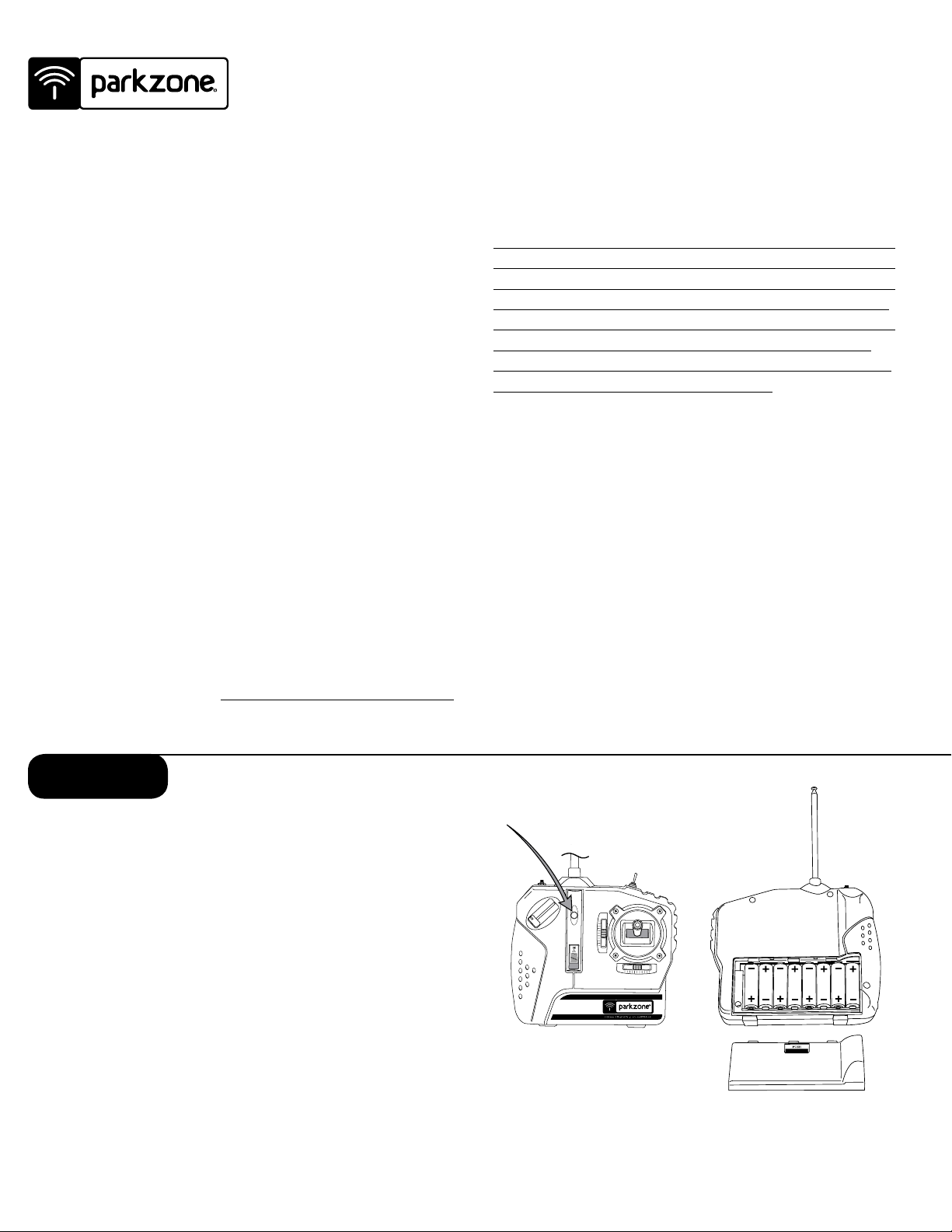
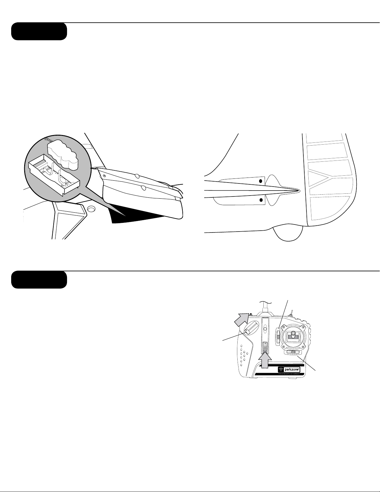
Step 1
Setting Up the Transmitter
1. Insert 8 new “AA” batteries (supplied) into the
transmitter, observing proper polarity.
2. Turn the switch on and check to make sure the
LED is illuminated, which indicates that the batteries have been installed correctly. Once this is
confirmed, turn the radio off.
3. You’ll need to replace the transmitter “AA” batteries whenever you hear the low-battery alarm
(beeping sound) being emitted from the transmitter. To elongate the life of your “AA” batteries,
remove them from your transmitter when you are
not using it.
2
Step 2
Charging the Aircraft Battery
The ParkZone® variable rate DC Peak charger
uses unique peak detection circuitry that ensures
an accurate charge every time and protects your
Ni-Cd and Ni-MH batteries from the dangers of
over-charging. This charger continually monitors
the battery’s charge curve and automatically stops
charging when the peak charge is detected. The
peak detection charger will help avoid damage to
your Ni-Cd and Ni-MH cells.
Important: The battery should be charged shortly
before flying. If you charge the battery 12 to 24
hours prior to flying, you will need to “re-peak” the
battery before you fly.
WARNING! You cannot charge the optional Li-Po
battery packs with the ParkZone variable rate DC
Peak charger included with this kit. You must use a
Li-Po specific battery charger. Failure to follow this
warning could result in a fire.
WARNING! Do not leave the charger or battery
unattended during the charge process. While charging, place the battery on a heat resistant surface
and constantly monitor the temperature of the battery pack. If the battery becomes hot at any time
during the charge process, discontinue charging
immediately. It should only be warm to the touch,
and should not feel warm until it is almost done
charging. Do not allow children to charge battery
packs without adult supervision.
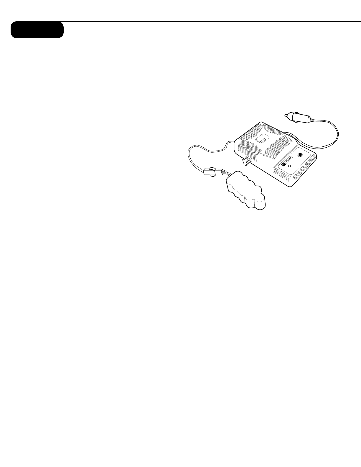
Variable Rate DC Peak
Detection Charger Features
• Variable charge rate from 0.5–1.8 amps
• Uses automobile 12V power outlet
• Charges 5- to 10-cell Ni-Cd and Ni-MH battery packs
• Trickle charge
• LED charge indicator
Using Your Variable Rate DC Peak Charger
1. Using the dial on the side of the charger, set the
charge rate at 1.4 amps.
2. Connect the battery pack to the charger using
the included adapter.
3. Connect the charger to the 12V power outlet in
your automobile. The LED will continually blink
while the battery charges.
4. Charging is finished when the LED indicator
glows steadily. (40 minutes or less)
Note: The charge time is only an estimate of a fully
discharged battery pack. Actual charge times may
vary. Damage to the charger and battery will occur
if you exceed the maximum charge rate recommended.
3
Step 3
Attaching the Wing
In order to attach the wing of your Focke-Wulf 190,
please follow these simple instructions:
1. Locate the included wing screws (in clear plastic
bag).
2. Plug in the aileron servo lead from the wing into
the aileron extension. This is very important, as
the ailerons will be reversed if this is not done.
3. Carefully attach the wing to the fuselage. Use 3
screws to secure the wing as shown.
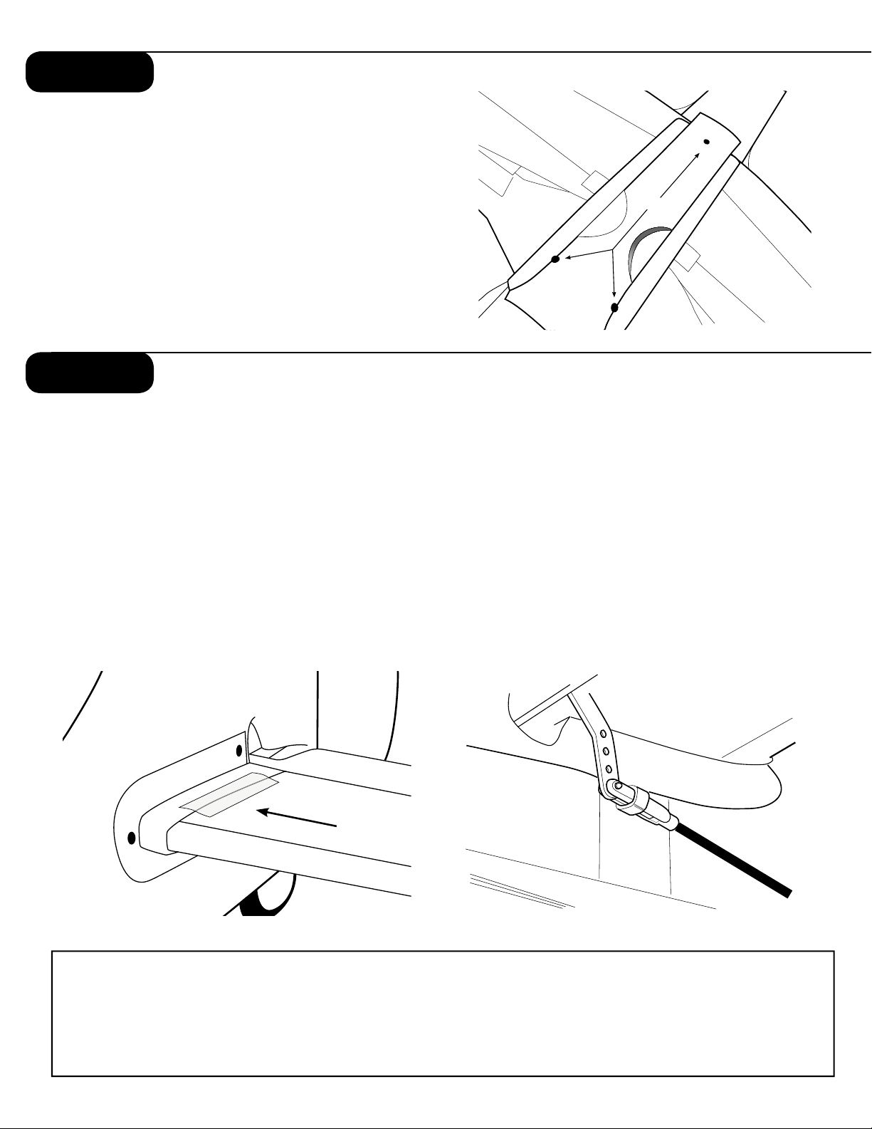
Step 4
Attaching the Horizontal Stabilizer
1. Locate the horizontal stab of the tail.
2. Slide the horizontal tail stab through the allotted
space in the fuselage, making sure the control
horn attached to the horizontal tail stab will properly align with pushrod and clevis exiting the back
of the fuselage.
3. When you are certain the tail is centered correctly, use the provided clear tape to properly secure
the tail to the fuselage, as shown. Use the tape
tape
on the top and bottom of each side of the tail
(total of 4 applications).
4. Make sure that the throttle slider is all the way
down, in the “off” position. Turn on the transmitter and plug in the flight battery. Make sure the
trim levers and control stick are centered.
5. Locate where the clevis and rod exit the fuselage, and attach the clevis to control surface as
shown.
6. Make necessary trim adjustments prior to flight.
See step 5 for instructions on how to do this.
Center of Gravity Information
The center of gravity (CG) of the ParkZone FW 190 is approximately 5 3/4” forward from the trailing edge of the
wing. You will notice two panel lines at this location and the CG is between those lines. This is for both the stock
9 cell Ni-MH and also a 3S LiPO pack.
You can confirm this by placing your fingers between these panel lines and balancing the plane while it is inverted.
4
Step 5
Making Trim Adjustments
to the Horizontal Stabilizer
1. Turn on transmitter.
2. Install a fully charged battery into the battery compartment and secure it with the included Velcro.
3. Set the elevator trim lever to center.
4. Make certain the elevator is set to neutral with
the horizontal stabilizer. Do this by removing the
clevis from the control horn and turning it on
the pushrod as needed. Once the adjustment is
made, reattach the clevis.
5. If you feel more adjustments are necessary while
in flight, move the trim lever on the transmitter a
Step 6
few “clicks” up or down as needed.
Motor Test
Warning: Keep everything clear of the propeller
before starting the motor test so you do not damage any property or harm anyone.
1. Make sure the throttle slider is in the “off” position.
2. Turn on the transmitter.
3. Plug the flight battery into the white lead inside
the fuselage.
5
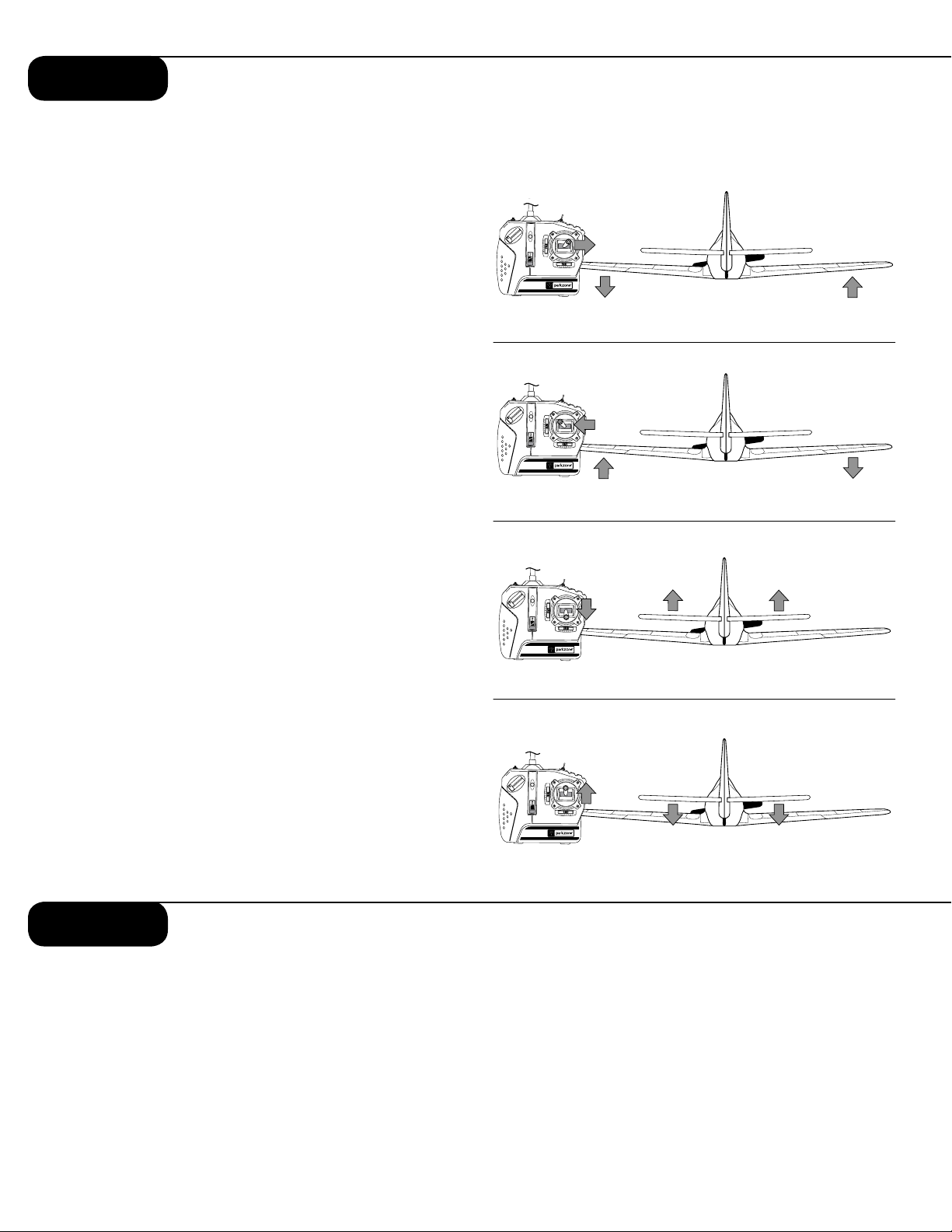
Step 7
Control Test
Warning: Keep everything clear of the propeller
before starting the control test in the event that you
accidentally turn on the motor.
1. Be certain that the throttle slider is in the “off”
position and that both trim levers are centered.
2. Switch on the transmitter and check to make sure
the LED is lit, indicating the transmitter has power.
3. Install the flight battery into the fuselage and plug
it into the battery connector.
4. Move the stick from side to side. The ailerons on
the trailing edge of the wings should move per
your transmitter input. When the stick is pushed to
the right, the right aileron should deflect upward
and the left aileron downward, and vice versa.
5. Pull the stick back and the elevator control surface should move upward (as shown).
6. Move the stick full forward. When this is done, the
elevator control surface should move down (as
shown).
7. When the test is complete, be sure to disconnect
the flight battery first, and then turn off the transmitter. This should be done each time you turn off
the airplane.
Note: It is very important to make sure that the
control surfaces are at 0 degrees when the transmitter control stick and trim levers are centered. (See
Steps 5 and 8 for making needed adjustments to
control surfaces.)
If your airplane is not responding correctly to the
transmitter input, do not fly! Some correction is
needed. Call the Horizon Product Support line
at 1-877-504-0233.
Step 8
Making Adjustments to the Ailerons
Warning: Keep everything clear of the propeller
before adjusting the ailerons in the event that you
accidentally turn on the motor.
You may find some adjustment is needed to properly trim the ailerons. The ailerons are properly
trimmed when each aileron is level with the stationary wing surface. To do this, follow these simple
instructions:
1. Make sure the throttle slider is in the “off” position and then turn on the transmitter.
2. Install the flight battery and plug it into the lead
from the fuselage.
3. Most trim adjustments to the ailerons can be
made with the aileron trim levers on the transmitter. Make sure the gimbal (stick) is at neutral
prior to making any trim changes.
6
 Loading...