

Page 1

ParkZone® products are distributed exclusively by
Horizon Hobby, Inc.
4105 Fieldstone Road
Champaign, IL 61822
Horizon Hobby UK
Units 1-4 Ployters Rd
Staple Tye
Southern Way
Harlow
Essex CM18 7NS
United Kingdom
Horizon Hobby Deutschland GmbH
Otto Hahn Str. 9a
25337 Elmshorn
Germany
The Spektrum trademark is used with permission of Bachmann Industries, Inc.
© 2008 Horizon Hobby, Inc.
parkzone.com
13485
Page 2

F4U Corsair PNP
Instruction Manual
Charge-and-Fly™ Park Flyer
Wingspan: 44 in (1118mm)
Length: 36 in (914mm)
Weight (RTF): 30 oz (875 g)
Servos: Four 3-wire servos
Motor: PKZ 480-size, 960Kv outrunner brushless motor
ESC: E-flite 30A brushless ESC with Switch-Mode BEC (EFLA1030)
Page 3

F4U Corsair Instruction Manual
Congratulations on your purchase of the ParkZone® F4U
Corsair Plug-N-Play® (PNP). One of the most popular
Warbirds of WWII, the Corsair was also one of the most
feared by the Axis powers. Nicknamed the “sweetheart
of Okinawa” by American pilots and “whistling death”
by the Japanese, the F4U’s most notable feature was
the “bent” wing that was necessary to allow clearance
for its massive propeller, which was powered by the
incredible Pratt and Whitney R-2800 Double Wasp radial
engine. You can now enjoy flying your own F4U with this
beautiful ParkZone replica.
This airplane comes almost fully assembled in order
to allow you to get in the air quickly. Your F4U Corsair
Plug-N-Play already has the 3-wire servos, a ParkZone
480 outrunner brushless motor and an E-flite Pro 30A
brushless ESC installed. The decals have already been
applied, as well. You will only need to add your own
battery and charger (a 3S 1800+mAh Li-Po battery is
recommended), as well as a receiver and transmitter. In
as little as an hour, you can be ready for your first flight
with the F4U Corsair PNP. This means you can spend
your time refining your flying skills, not your building
skills.
Warning:
Although your ParkZone F4U Corsair PNP comes almost ready to fly, this aircraft is for experienced RC pilots only
and is not a toy! Misuse of the plane can cause serious bodily harm and damage to property. Therefore, only an
experienced RC pilot should fly it.
If you are not experienced at flying one of HobbyZone’s 3-channel aircraft, or any other 3-channel radio controlled
aircraft, we recommend that you do not fly this aircraft. If you still choose to fly, you will need to seek the help of
an experienced radio control pilot during your first several flights. This is especially important if you have not flown
a 3-channel airplane with aileron control as one of the channels. Crash damage is not covered under the warranty.
Caution!
Changes or modifications not expressly approved by the party responsible for compliance could void the user’s
authority to operate the equipment.
3
Page 4
Step 1
Charging Your Flight Battery
We recommend that you choose either the 2200mAh
3S Li-Po (PKZ1030) or the ParkZone 1800mAh 3S
Li-Po (PKZ1031) to power your F4U Corsair PNP. The
Li-Po battery must be charged with a charger that is
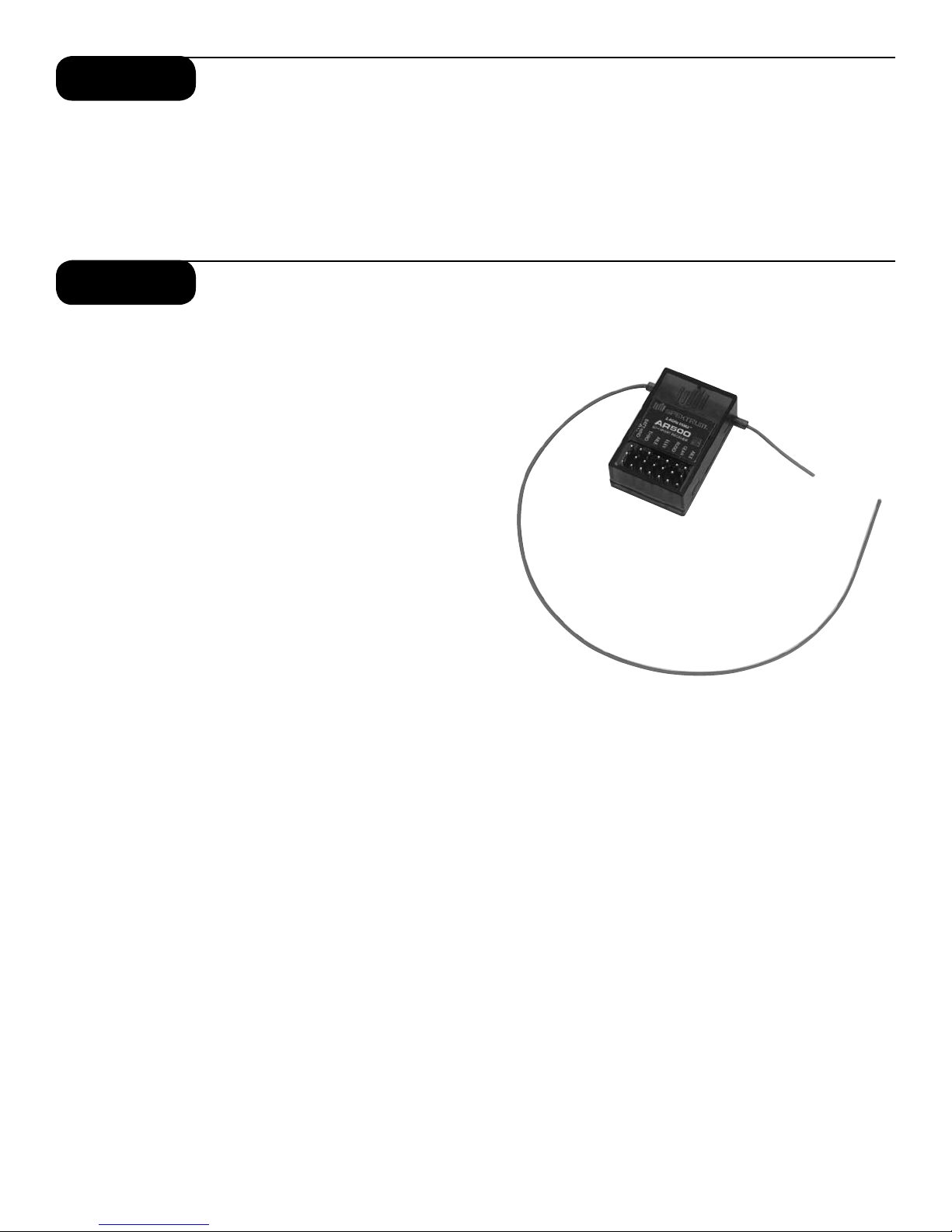
Step 2
Installing the Receiver
Carefully plug in the servo leads into the corresponding
channels of the receiver you have chosen. Confirm that
the servo leads/plugs are in the correct channel of the
receiver. Do this by:
1. Turning on the transmitter. (Refer to your radios
instructions for further information)
2. Installing a charged flight battery.
3. Plugging flight battery into ESC.
4. Checking all functions to ensure proper setup.
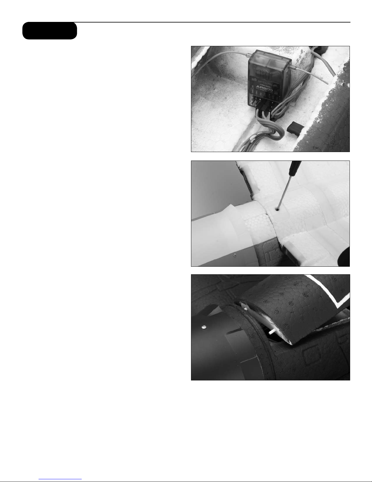
Keep all body parts away from the propeller. You can
also make any trim adjustments to the control surfaces
at this time. Once you are satisfied that the channels
are functioning correctly, you can turn off the radio
system. Install the receiver into the allotted space within
the fuselage. Make sure it is secure. Carefully route the
antenna (when applicable) so it exits the fuselage just
behind the canopy. It should then simply fall along the
fuselage and can be secured through the vertical stab.
When the antenna is routed correctly, it should hang
several inches (5”–7”) below the fuselage.
specifically designed to handle Li-Po batteries, such
as the ParkZone 2- to 3-cell Li-Po Charger (PKZ1040).
Regardless of the battery you choose, always follow the
charger and battery instructions in order to avoid any
damage to the battery, charger, property or yourself.
4
Page 5
Step 3
Attaching the Wing
In order to attach the wing of your Corsair PNP, please
follow these simple instructions:
1. Locate the wing securing screw (3mm x 30mm) in
the box.
2. Remove the canopy hatch by gently pulling up on
the back of the hatch and set it aside. Removing
the hatch will aid in routing the aileron leads from
the wing into the fuselage.
3. Turn over the fuselage so you are looking at the
bottom. Do the same with the wing.
4. Carefully align the two locator pins on the back of
the wing into the two small holes in the back of the
fuselage.
5. Route the aileron leads through the access hole in
the bottom of the fuselage.
6. Slide the aileron leads inside the fuselage so that
they will not become pinched in between the wing
and the fuselage when securing the wing.
7. Slide the leading edge of the wing into the fuselage
as shown, making certain it is perfectly centered.
This must be done correctly in order to allow the
screw to thread into the fuselage. Once you are
certain the wing is centered, tighten the screw to
secure the wing.
8. Connect the aileron leads to the included
Y-harness, noting proper orientation.
9. Replace the canopy by aligning the pins on the
front of the hatch with the fuselage. The magnet at
the rear of the hatch will ensure it is secure.
5
Page 6

Step 4
Installing the Landing Gear
Install the main landing gear by inserting the wire into
the locator hole in the wing. Swivel the landing gear
toward the retaining clips and gently snap into place.
NOTE: The landing gear is directional. When properly
installed, the landing gear will rake forward to add
stability in landing. If the gear does not angle forward
when installed, simply reverse the landing gear.
Installing Landing Skids (Optional)
Two landing gear skids have been included with the F4U
Corsair PNP should you choose to fly without the
landing gear. To install, simply apply the skids over
the landing gear mounts and secure with the included
screws. The rear edge of the skids can be secured to
the Z-Foam using double-sided tape.
6
Page 7

Step 5
Attaching the Horizontal Stabilizer
1. Locate the horizontal stabilizer of the tail.
2. Slide the horizontal stabilizer in the allotted space
of the fuselage, making sure the control horn
installed in the elevator will properly align with the
pushrod and clevis exiting the back of the fuselage.
3. When you are certain the horizontal stabilizer is
centered correctly and in the right place, use the
tape provided to properly secure the stabilizer to
the fuselage. Use the tape on the top and bottom
of each side of the horizontal stabilizer (total of 4
applications).
4. Make sure the throttle stick is in the full down (idle)
position. Turn on the transmitter and plug in the
flight battery.
5. Locate the lower clevis and pushrod exiting the
right side of the fuselage, and attach the clevis to
the outermost hole on the elevator control horn.
Slide the included retainer over the clevis to ensure
the clevis will not open.
6. Make any trim adjustments as necessary prior to
flight (see step 7).
a. Confirm the throttle stick is in the full down (idle)
position and turn on the DX5e transmitter.
b. Connect the blue EC3 battery connector into the
EC3 device connector on the speed control.
c. Use the elevator trim of the radio by moving up or
down to achieve neutral position when the gimbal is
also at neutral. If these changes are not sufficient,
center the transmitter elevator trim (distinguished by
a long tone), then remove the clevis from the elevator
control horn and turn clevis in or out as needed to
move the elevator alignment back to neutral.
Warning: Always keep hands and all objects away
from the propeller in case the motor is engaged.
A moving propeller can cause severe injury and
damage.
Note: To make trim adjustments to the horizontal
stabilizer:
Step 6
Installing or Replacing the Propeller and
Spinner
Your F4U Corsair has come with 2 different propellers.
• The 2-blade (installed) propeller is slightly more
efficient and offers a little more thrust.
• The 3-blade propeller allows for more scale-type
flights, yet performs very well.
1. Remove the prop hub by inserting a hex driver
through the holes drilled in the hub. Carefully
grasp the propeller and turn the prop hub counterclockwise to loosen the hub.
2. Slide propeller on. Make sure pitch numbers on
prop are visible from the front of the airplane.
3. Re-install the prop hub by turning it clockwise. The
hex driver should be used as in Step 1 to ensure
the hub is tight.
7
NOTE: Always confirm the flight battery is unplugged
from the speed control prior to working around the
propeller and cowl.
Page 8

Step 7
30A ESC instructions
The E-flite 30A Pro Brushless ESC is a lightweight, highquality, efficient sensorless brushless electronic speed
control with an integrated switch-mode BEC. It can operate without the need for a separate receiver battery to
power your servos and receivers, saving you weight and
complication. It is capable of up to 30 amps continuous
current when using 3- to 4-series LiPo battery packs.
You can drive up to 5 analog or 4 digital sub-micro-sized
servos with the BEC on any recommended input voltage.
This ESC also features safe power arming along with
advanced programmable features such as low voltage
cutoff, braking, timing, throttle input range, and more,
making this truly a ‘pro series’ speed control. The ESC
installed in the F4U Corsair has been pre-programmed
for 3S low voltage cut-off.
Note: ALWAYS assume the motor and the propeller
are live. ALWAYS keep clear of the propeller at all
times. The high rpm of the brushless motor can
cause severe injury.
E-flite 30-Amp ESC Features:
• Up to 30 amps continuous current with proper air
flow and 35 amps burst current (15 seconds)
• 5V switch-mode BEC capable of 700mAh
continuous current on any recommended
input voltage
• Drive up to 5 analog or 4 digital sub-micro-sized
servos with the BEC on any recommended
input voltage
• 3- to 4-cell LiPo, 9- to 12-cell NiMH/NiCd
input voltage
• Programmable motor braking
• Safe power-arm mode prevents accidental starts
• Programmable low voltage cutoff with settings
for 3-cell LiPo (9.2V), 4-cell LiPo (12V), or 74% of
battery starting voltage
• Programmable throttle input range (1.1ms–1.9ms
or 1.2ms–-1.8ms)
• Programmable soft start for helis and airplanes
• Auto motor shut down if signal is lost or there is
interference
• Programmable timing—5 user-selectable ranges–
use with a large variety of brushless motors
• Optional RS232 Serial Link and software available
for PC programming (EFLARS232)
• Pre-wired connectors—E-flite EC3 on battery input
and 3.5mm female gold bullets on motor
output leads
Specifications
Continuous Current: 30A*
Max Burst Current: 35A (15 sec)*
Length: 51mm (2 in)
Width: 28mm (1.1 in)
Height: 8.7mm (.35 in)
Weight: 31 g (1.1 oz)
Cells: 3-4S LiPo or 9-12 NiMH/NiCd
Battery Input Leads: 16 AWG with E-flite
EC3 Connector
Motor Output Leads: 16 AWG with 3.5mm Female
Gold Bullet Connectors
* Proper cooling required
Optional RS232 Serial Link & Programming Software
Programming your ESC will be much faster and easier
when you purchase the optional RS232 Serial Link and
programming software. This will allow you to update
your ESC using a laptop or PC. You must have a Serial
Port on your computer or you can purchase a separate
USB to DB9 adapter (available at computer retailers).
EFLARS232—RS232 Serial Link/Programming Software
Servo Ratings with BEC Enabled:
Drives up to 5 analog or 4 digital sub-micro-sized servos
with the BEC on any recommended input voltage.
Some servo combinations we have tested in various
models include:
• 1 analog standard servo, 1 digital sub-micro servo,
2 analog sub-micro servos—E-flite Apprentice
15e RTF
• 2 ParkZone (PKZ1081) analog sub-micro servos
and 2 ParkZone (PKZ1090) digital metal gear
sub-micro servos—ParkZone T-28 Trojan RTF &
F4U Corsair RTF
Some other brands and models of servos may have
significantly higher current draw. Digital servos and
binding servos of any kind typically have higher current
draw. As a general rule, micro and sub-micro servos
draw less current which may affect your servo usage
as shown in the examples above. We recommend the
use of a Hangar 9 Servo and Receiver Current Meter
(HAN172), installed between the throttle lead of the
ESC and receiver, to confirm current draw of the actual
servos used. Also, always be sure to position the ESC
for maximum airflow since cooling can significantly aid
in the performance of the BEC.
8
Page 9

Step 7 cont.
Before first use, please refer to “Servo Ratings with BEC
Enabled” notes for BEC usage guidelines. You must
follow these guidelines for safe operation. If you are
using more than 5 analog sub-micro-sized servos, more
than 4 digital sub-micro-sized servos, or servos with
higher current draw than the BEC can deliver, you will
need to disable the BEC. If you wish to disable the BEC,
you must remove the red receiver wire lead and
connector from the receiver lead housing, and then
insulate it properly to prevent shorting. When operating
with the BEC disabled, E-flite recommends the use of
a separate, high-power, external BEC (like the Ultimate
BEC), or receiver pack and switch using the following
items to ensure trouble-free operation:
1. JR 1100mAh 4.8V Ni-MH receiver battery
(JRPB4240), or similar
2. JR Switch Harness (JRPA003), or similar
Before you connect your ESC and begin flying, take
a moment to look it over. The input power side has a
black (negative) and red (positive) wire along with an
E-flite EC3 Male Device Connector. The motor side has
three 16-gauge wires (blue, red, and black) with 3.5mm
female gold bullet connectors on the ends.
The black and red wires with the EC3 Device (DEV)
Connector will connect to your power battery. The red
wire connects to the red wire on your battery pack, the
black wire connects to the black wire on your battery
pack. If the wires are reversed, the ESC may be damaged. YOU MUST ENSURE THAT YOU CONNECT THE
BATTERY POLARITY PROPERLY TO PREVENT DAMAGE
TO THE ESC. Reversing polarity will void your warranty,
so always double-check this connection. Use only a
genuine E-flite EC3 Female Battery (BATT) connector on
the battery so it matches the EC3 Male Device (DEV)
connector on the speed control. The throttle lead
connects to the throttle channel on your radio receiver.
WARNING: For your safety, when checking the startup
function of the ESC or making programming changes,
please remove the propeller to prevent any potential
injury. You should always treat the motor and propeller
as live and dangerous, remembering it could start at
any time, and keep any body parts, clothing and tools
clear of the propeller arc. NEVER LEAVE THE BATTERY
CONNECTED WHEN NOT FLYING THE AIRCRAFT AND
ALWAYS REMOVE THE BATTERY FROM THE MODEL
BEFORE CHARGING AND WHEN FINISHED FLYING.
9
When flying in hot weather, we recommend checking on
the condition of the ESC, battery, and motor after each
flight. You may want to consider letting the electronic
components cool to near ambient temperature between
flights. We also recommend throttle management when
running near maximum levels of current draw during
extreme conditions. It is not recommended you fly an
entire flight at full throttle. If this is done, it is possible to
cause permanent damage to your motor, battery, and
ESC.
Using the 30-Amp Pro Switch-Mode BEC
Brushless Controller
This controller is very simple to use, and for safety,
will not arm the motor until the throttle stick has been
held in the Idle/Off position for more than 1 second.
The controller will indicate the soft cutoff voltage setting every time you plug the battery in by first emitting
a low, long tone, to indicate startup. Depending on the
selected cutoff voltage (default is 74%), you will then
hear the respective number of medium length mid tones
to indicate the cell count or a musical tone for the 74%
cutoff, helping you to confirm the setting before every
flight. Proper air cooling is required during flights so the
ESC should be placed in an area where air flows over
the controller.
Connecting the ESC to the Motor
The three wires from the motor connect to the three
female gold bullet connectors on the ESC. The order
of connection to the motor is not important; any motor
wire can be plugged into any connector. If the motor
runs backwards, you can simply unplug and switch any
two of the motor wire plugs connected to the ESC.
Mounting the ESC
Choose a location that has good airflow and offers good
protection. Do not cover the side with the flat heat shield
with hook and loop or tape as this will greatly reduce
its effectiveness. Mount the ESC with a combination of
hook and loop, 2-sided foam tape, and/or tie wraps.
Starting Your Power System
1. Turn on your transmitter and ensure the position of
the throttle stick is set to Idle/Off.
2. Plug the battery pack into the controller. You will
hear 1 low long tone to indicate startup, then the
respective number of medium-length mid tones to
indicate the cell count or a musical tone for the
74% cutoff, followed by 3 rising tones to indicate
the controller is armed.
Page 10

3. When you move the throttle stick upward, the
motor will run. Continue to move the throttle stick
upward to the full throttle (high) position, and the
motor will run faster. When the throttle stick goes
below the start-up position, the motor will stop
running.
4. Check servo motion as part of your preflight
check. It is very important to make sure linkages
are free-moving with no binding.
Remember, when in the programming mode:
Full Throttle = Stick Up
Idle = Stick Down
The default settings (from the package) for your E-flite
30-Amp Pro ESC are as follows:
• Voltage cutoff set at 74%
• Brake set to Off
• Timing set at 15 degrees
• Throttle Input Range set at 1.2ms to 1.8ms
• Start-up Rate (Acceleration Delay) set at 0.25
seconds
• PWM Frequency set at 8KHz
• Operating Mode set to normal (airplane)
Entering the Programming Mode
1. With the battery disconnected from the controller,
and the transmitter turned on, first move the
throttle stick to full throttle (>1.7ms) position.
Leave it in this position and then connect the
battery to the controller.
2. Wait for 5 seconds, and the ESC will give two
sets of fast ringing tones to indicate you have
successfully entered the programming mode.
3. Once you hear these tones, move the stick to
center (between 1.4 and 1.7ms) for 5 seconds,
and the controller will beep 1 time, indicating you
are now in Menu 1.
4. The controller will now wait 5 seconds for you to
make your selection; your programming options
are either full throttle (>1.7ms) or idle (<1.3ms).
5. When you have made a valid selection, the control
will beep once with a lower tone, and you can
move the stick back to center for the next menu
item (2 beeps, 3 beeps and so on). If you do not
make a selection within 5 seconds, the controller
will move to the next menu item.
6. If you want to make changes in the programming
menus (see specific instructions below) move the
throttle stick to full throttle (>1.7ms) position. You
will have 5 seconds to make your selection.
7. If you want to advance to the next menu, allow the
programming to skip to the next menu after the 5
seconds have expired.
Programming Menu 1—Voltage Cutoff
Use this option to set the voltage at which the controller will shut down the motor to prevent damage to your
battery when it reaches the cutoff voltage. You will know
your battery pack has reached auto cutoff when
you hear the motor “pulse” repeatedly.
1. Move the throttle stick to full throttle (>1.7ms)
position to make changes to the voltage cutoff
programming.
a.To select 3-cell low voltage cutoff – You will
hear 3 short beeps. Move the throttle stick to
center (between 1.4 and 1.6ms). The controller
will beep 2 times, indicating you have set the
program selection or leave in full throttle for 5
seconds to advance to the next selection.
b. To select 4-cell low voltage cutoff—You will
hear 4 short beeps. Move the throttle stick to
center (between 1.4 and 1.6ms). The controller
will beep 2 times, indicating you have set the
program selection or leave in full throttle for 5
seconds to advance to the next selection.
c. To select 5-cell low voltage cutoff—You will
hear 5 short beeps. Move the throttle stick to
center (between 1.4 and 1.6ms). The controller
will beep 2 times, indicating you have set the
program selection or leave in full throttle for 5
seconds to advance to the next selection.
IMPORTANT NOTE ABOUT 74% CUTOFF: This
option will activate the soft cutoff at 74% of startup
voltage or 9.2V, whichever is higher. For example, if
your pack measures 16.8 volts at startup, then the
soft cut will occur at 12.4 volts. The 74% cutoff option
will check the startup voltage every time you plug the
battery into the controller, so beware of using partially
charged packs, as the system cannot protect your LiPo
batteries if you are using the 74% cutoff and connect
a partially charged pack. You will know your battery
pack has reached soft auto cutoff when you hear the
motor “pulse” repeatedly. We recommend you land
your model as soon as you hear the motor pulse (indicating the pack voltage has dropped to the cutoff voltage level) to prevent over-discharge of the LiPo battery
pack, and to prevent sudden power loss.
10
Page 11

Step 7 cont.
Programming Menu 2 —Brake Type
The default setting is Brake Off. This option gives you
the choice to have the ESC stop the propeller during
flight (Brake On) or allow it to windmill (Brake Off). Use
the Brake On options for folding propellers.
1. Move the stick to center (between 1.4 and 1.6ms)
for 5 seconds, and the controller will beep 2 times,
indicating you are now in Menu 2.
2. Move the throttle stick to full throttle (>1.7ms)
position to make changes to the Brake Type
programming.
a. To select No Brake/Brake Off – You will hear
1 short beep.Move the throttle stick to center
(between 1.4 and 1.6ms). The controller will
beep 2 times, indicating you have set the
program selection or leave in full throttle for 5
seconds to advance to the next selection.
b. To select Soft Brake – You will hear 2 short
beeps. Move the throttle stick to center
(between 1.4 and 1.6ms). The controller will
beep 2 times, indicating you have set the
program selection or leave in full throttle for 5
seconds to advance to the next selection.
c. To select Medium Brake – You will hear 3
short beeps. Move the throttle stick to center
(between 1.4 and 1.6ms). The controller will
beep 2 times, indicating you have set the
program selection or leave in full throttle for 5
seconds to advance to the next selection.
d. To select Hard Brake – You will hear 4 short
beeps. Move the throttle stick to center (between 1.4 and 1.6ms). The controller will beep
2 times, indicating you have set the program
selection or leave in full throttle for 5 seconds to
advance to the first selection again.
Programming Menu 3—Timing
The default setting is 15 degrees. As a general rule,
lower pole count motors use lower timing and higher
pole count motors use higher timing. Please refer to
your motor instructions and specifications for an
indication of the number of poles.
Low Timing Advance
Timing Degrees – 5 & 10
Motor Poles – 2 to 4
Expected Performance – Good balance of power and
efficiency
Motor Poles – 6 or more
Expected Performance – Best efficiency and run time
(lowest power)
11
Standard Timing Advance
Timing Degrees – 15 & 20
Motor Poles – 6 to 12
Expected Performance – Good balance of power and
efficiency
Motor Poles – 14 or more
Expected Performance – Best efficiency and run time
(lowest power)
High Timing Advance
Timing Degrees – 25
Motor Poles – 12
Expected Performance – Highest power, less efficiency
Motor Poles – 14 or more
Expected Performance – Good balance of power and
efficiency
1. Move the stick to center (between 1.4 and 1.6ms)
for 5 seconds, and the controller will beep 3
times, indicating you are now in Menu 3.
2. Move the throttle stick to full throttle (>1.7ms)
position to make changes to the Timing
programming.
a. To select 5 Degrees – You will hear 1 short
beep. Movethe throttle stick to center
(between 1.4 and 1.6ms). The controller will
beep 2 times, indicating you have set the
program selection or leave in full throttle for
5 seconds to advance to the next selection.
b. To select 10 Degrees – You will hear 2 short
beeps. Move the throttle stick to center
(between 1.4 and 1.6ms). The controller will
beep 2 times, indicating you have set the
program selection or leave in full throttle for
5 seconds to advance to the next selection.
c. To select 15 Degrees – You will hear 3 short
beeps. Move the throttle stick to center
(between 1.4 and 1.6ms). The controller will
beep 2 times, indicating you have set the
program selection or leave in full throttle for
5 seconds to advance to the next selection.
d. To select 20 Degrees – You will hear 4 short
beeps. Move the throttle stick to center
(between 1.4 and 1.6ms). The controller will
beep 2 times, indicating you have set the
program selection or leave in full throttle for
5 seconds to advance to the next selection.
e. To select 25 Degrees – You will hear 5 short
beeps. Move the throttle stick to center
(between 1.4 and 1.6ms). The controller will
beep 2 times, indicating you have set the
Page 12

program selection or leave in full throttle for
5 seconds to advance to the first
selection again.
Programming Menu 4—Throttle Input
Range (PWM)
The default setting is 1.2ms to 1.8ms and should work
with most radio systems. This option allows for proper
throttle input with many different radio systems. However, some radios have a wider output range, and may
give a more linear response with the 1.1ms to 1.9ms
range. If you feel there is too much “dead” area in the
stick movement near full throttle, try adjusting the end
points in your radio, or change to the wider input range.
Be aware that if these settings are not correct, it may
be impossible to arm the controller.
1. Move the stick to center (between 1.4 and 1.6ms)
for 5 seconds, and the controller will beep 4
times, indicating you are now in Menu 4.
2. Move the throttle stick to full throttle (>1.7ms)
position to make changes to the Throttle Input
Range programming.
a. To select 1.2ms to 1.8ms – You will hear 1
short beep. Move the throttle stick to center
(between 1.4 and 1.6ms). The controller will
beep 2 times, indicating you have set the
program selection or leave in full throttle for
5 seconds to advance to the next selection.
b. To select 1.1ms to 1.9ms – You will hear 2
short beeps. Move the throttle stick to center
(between 1.4 and 1.6ms). The controller will
beep 2 times, indicating you have set the
program selection or leave in full throttle for 5
seconds to advance to the first
selection again.
Programming Menu 5—Start-Up Rate
The default setting is 0.25 seconds. The start-up rate
is the time it takes to reach maximum motor speed.
Changing the setting to 1 second can be useful with
power-fragile gear boxes.
1. Move the stick to center (between 1.4 and 1.6ms)
for 5 seconds, and the controller will beep 5
times, indicating you are now in Menu 3.
2. Move the throttle stick to full throttle (>1.7ms)
position to make changes to the Start-up Rate
programming.
a. To select .25 second – You will hear 1 short
beep. Move the throttle stick to center
(between 1.4 and 1.6ms). The controller will
beep 2 times, indicating you have set the
program selection or leave in full throttle for
5 seconds to advance to the next selection.
b. To select 1 second – You will hear 2 short
beeps. Move the throttle stick to center
(between 1.4 and 1.6ms). The controller will
beep 2 times, indicating you have set the
program selection or leave in full throttle for 5
seconds to advance to the first
selection again.
Programming Menu 6 —PWM Switching
Frequency
The default setting is 8KHz, which should be acceptable
for most motors. If you have a low or very low inductance motor and know you need to use a higher PWM
Frequency (refer to the manual included with the motor),
then you can change the setting. Otherwise, we recommend leaving the default setting.
1. Move the stick to center (between 1.4 and 1.6ms)
for 5 seconds, and the controller will beep 6
times, indicating you are now in Menu 6.
2. Move the throttle stick to full throttle (>1.7ms)
position to make changes to the PWM Switching
Frequency programming.
a. To select 8KHz PWM Frequency – You will
hear 1 short beep. Move the throttle stick
to center (between 1.4 and 1.6ms). The
controller will beep 2 times, indicating you
have set the program selection or leave in full
throttle for 5 seconds to advance to the
next selection.
b. To select 16KHz PWM Frequency – You will
hear 2 short beeps. Move the throttle stick
to center (between 1.4 and 1.6ms). The
controller will beep 2 times, indicating you
have set the program selection or leave in
full throttle for 5 seconds to advance to the
next selection.
c. To select 32KHz PWM Frequency – You will
hear 3 short beeps. Move the throttle stick
to center (between 1.4 and 1.6ms). The
controller will beep 2 times, indicating you
have set the program selection or leave in full
throttle for 5 seconds to advance to the first
selection again.
12
Page 13

Step 7 cont.
Programming Menu 7—Operating Mode
The default setting is set to Normal (airplane) Mode,
which is limited to a start-up rate of 0.25 or 1 second.
Alternatively, the Heli Mode can be selected which reduces the start-up rate to 5 seconds for the first start-up
and any start-up after the motor/ESC has been stopped
for more than 5 seconds. This helps to prevent
damaging the motor, gears or any other components
from an abrupt start-up when none of the parts are
moving. Any time the motor/ESC has been stopped for
less than 5 seconds in Heli Mode, the start-up will be immediate. This allows power to be applied immediately,
such as when aborting an auto-rotation attempt or for
any other reason, to help prevent a crash. Remember,
you must wait more than 5 seconds after stopping the
motor/ESC in order for the 5-second start-up to occur
again.
1. Move the stick to center (between 1.4 and 1.6ms)
for 5 seconds, and the controller will beep 7
times, indicating you are now in Menu 7.
2. Move the throttle stick to full throttle (>1.7ms)
position to make changes to the Operating mode
programming.
a. To select Normal mode – You will hear 1
short beep. Move the throttle stick to center
(between 1.4 and 1.6ms). The controller will
beep 2 times, indicating you have set the
program selection or leave in full throttle for
5 seconds to advance to the next selection.
b. To select Heli mode – You will hear 2 short
beeps. Move the throttle stick to center
(between 1.4 and 1.6ms). The controller will
beep 2 times, indicating you have set the
program selection or leave in full throttle for
5 seconds to advance to the first
selection again.
Troubleshooting
The controller will beep more quietly than normal if the
input voltage is below the cutoff voltage when the
battery is connected. Check the voltage of the battery
pack to see if it is correct (charged), or the programmed
cutoff setting if the input voltage is set incorrectly for
the voltage of the pack being used.
If you have trouble arming the controller (and the throttle
stick and throttle trim have been set to minimum), enter
the programming mode and try changing the setting to
1.1ms–1.9ms in Programming Menu 4 to see if it helps
correct the problem. If it is a computer radio, you may
alternatively increase high and low throttle ATV (endpoint)
percentages.
Note: Increasing the high ATV will not have a
consequence on arming issues, only low ATV.
Some transmitters, including all Futaba transmitters, will
require the throttle channel to be “reversed” for proper
operation.
13
Page 14

Step 8
Range Test
After you have finished the final assembly,
it is time to range check the radio system within the
F4U Corsair PNP.
Prior to each flying session:
Make sure that no one around may be flying, or is
getting prepared to fly, on the same channel that you
are on. After this is confirmed, turn on the transmitter
prior to plugging in the flight battery. With the airplane
on the ground and motor running, you should walk away
approximately 100 feet (35 meters) and still have full
control of all functions. If this is not the case, do not fly!
Call the Horizon Support Team at 1-877-504-0233.
Step 9
Flying
Always choose a wide-open space for flying your
ParkZone F4U Corsair PNP. It is ideal for you to fly at
an AMA sanctioned flying field. If you are not flying at
an AMA approved site, always avoid flying near houses,
trees, wires and buildings. You should also be careful
to avoid flying in areas where there are many people,
such as busy parks or school yards. Always follow local
ordinances. We recommend only flying your Corsair in
light winds.
WIND
Fly in this area
(upwind of pilot)
600 feet
Prior to each flight:
•Always make sure your F4U Corsair PNP is properly
trimmed.
• Always make sure the receiver, ESC, and battery
are properly secured.
• Always verify the propeller is on securely.
• Always ensure the servo reversing switches on the
transmitter are set correctly.
• Always verify the dual rates switch is set at where
you plan on flying. We recommend LOW rates for
your initial flying. The F4U Corsair PNP is VERY
maneuverable on high rates and requires a lot of
experience to handle properly.
Center of Gravity Location:
The center of gravity on your F4U Corsair PNP should
be located approximately 2-1/2” (63mm) behind the
leading edge of the wing, when measured against the
fuselage. This CG location has been determined with
the ParkZone 1800mAh 11.1V Li-Po battery installed.
Stand here
14
Page 15

Replacement Parts
Make sure that you keep your F4U Corsair flying. Replacement parts are available at your local hobby shop or from
Horizon Hobby (www.horizonhobby.com). Please try your local hobby shop first. By supporting them, they will be
there when you need them!
Item #: Description:
PKZ1012 2-Blade Propeller (9.5x7.5): T28/Corsair
PKZ1015 3-Blade Propeller (8.7x6): T28/Corsair
PKZ1016 Prop Hub: Corsair
PKZ1062 Servo Gear Set: SV80 Servo (Ailerons)
PKZ1063 Servo Y-Harness: Corsair/3D2/T28
PKZ1064 Metal Gear Set: DSV130M
PKZ1081 SV80 Servo (long lead): Ailerons
PKZ1090 DSV130M Servo (short lead): Rudder and Elevator
PKZ4416 480 Outrunner Brushless Motor: T28/Corsair
PKZ4418 Motor Shaft: 480 Outrunner
PKZ4428 Motor Mount: T28/Corsair
PKZ4603 Decal Sheet: Corsair
PKZ4606 Main Landing Gear: Corsair
PKZ4607 Tail Wheel: Corsair
PKZ4613 Clear Canopy & Painted Pilot w/Hatch: Corsair
PKZ4620 Painted Wing w/Details (No Servo): Corsair
PKZ4621 Wing Mounting Screw (3x30mm)
PKZ4622 Pushrods w/Clevis: Corsair
PKZ4623 Landing Gear Blocks: T28/Corsair
PKZ4624 Landing Gear Doors: Corsair
PKZ4625 Horizontal Tail w/Accessories: Corsair
PKZ4626 Cowl: Corsair
PKZ4627 Landing Skids: Corsair
PKZ4629 Wing Radiators: Corsair
PKZ4667 Painted Bare Fuselage: Corsair
EFLA1030 30-Amp Pro Brushless ESC
Optional Parts
PKZ1030 2200mAh 11.1V Li-Po Battery
PKZ1031 11.1V 1800mAh Li-Po Battery
PKZ1040 2- to 3-Cell DC Li-Po Balancing Charger
HBZ6513 Alligator Clip: 12V Adapter
EFLC505 1–5 Cell Li-Po Charger with Balancer
THP1205P AC to 12VDC, 5.0-Amp Power Supply: EFLC505
SPMAR500 AR500 DSM2 5-Channel Sport Receiver
SPM6600 DX6I 6-channel Full Range Radio System w/o Servos
15
Page 16

Warranty and Follow-Up Procedures
Warranty Period:
Exclusive Warranty- Horizon Hobby, Inc., (Horizon)
warranties that the Products purchased (the “Product”)
will be free from defects in materials and workmanship
at the date of purchase by the Purchaser.
Limited Warranty
(a) This warranty is limited to the original Purchaser
(“Purchaser”) and is not transferable. REPAIR OR
REPLACEMENT AS PROVIDED UNDER THIS WARRANTY
IS THE EXCLUSIVE REMEDY OF THE PURCHASER. This
warranty covers only those Products purchased from an
authorized Horizon dealer. Third party transactions are
not covered by this warranty. Proof of purchase is required for warranty claims. Further, Horizon reserves the
right to change or modify this warranty without notice
and disclaims all other warranties, express or implied.
(b) Limitations- HORIZON MAKES NO WARRANTY OR
REPRESENTATION, EXPRESS OR IMPLIED, ABOUT
NON-INFRINGEMENT, MERCHANTABILITY OR FITNESS
FOR A PARTICULAR PURPOSE OF THE PRODUCT. THE
PURCHASER ACKNOWLEDGES THAT THEY ALONE HAVE
DETERMINED THAT THE PRODUCT WILL SUITABLY
MEET THE REQUIREMENTS OF THE
PURCHASER’S INTENDED USE.
(c) Purchaser Remedy- Horizon’s sole obligation hereunder shall be that Horizon will, at its option, (i) repair or
(ii) replace, any Product determined by Horizon to be
defective. In the event of a defect, these are the
Purchaser’s exclusive remedies. Horizon reserves the
right to inspect any and all equipment involved in a
warranty claim. Repair or replacement decisions are
at the sole discretion of Horizon. This warranty does
not cover cosmetic damage or damage due to acts of
God, accident, misuse, abuse, negligence, commercial
use, or modification of or to any part of the Product.
This warranty does not cover damage due to improper
installation, operation, maintenance, or attempted repair
by anyone other than Horizon. Return of any goods by
Purchaser must be approved in writing by Horizon
before shipment.
Damage Limits:
HORIZON SHALL NOT BE LIABLE FOR SPECIAL,
INDIRECT OR CONSEQUENTIAL DAMAGES, LOSS OF
PROFITS OR PRODUCTION OR COMMERCIAL LOSS IN
ANY WAY CONNECTED WITH THE PRODUCT, WHETHER
SUCH CLAIM IS BASED IN CONTRACT, WARRANTY,
NEGLIGENCE, OR STRICT LIABILITY. Further, in no event
shall the liability of Horizon exceed the individual price of
the Product on which liability is asserted. As Horizon has
no control over use, setup, final assembly, modification
or misuse, no liability shall be assumed nor accepted for
any resulting damage or injury. By the act of use, setup
or assembly, the user accepts all resulting liability.
If you as the Purchaser or user are not prepared to
accept the liability associated with the use of this
Product, you are advised to return this Product
immediately in new and unused condition to the place
of purchase.
Law: These Terms are governed by Illinois law (without
regard to conflict of law principals).
Safety Precautions:
This is a sophisticated hobby Product and not a toy. It
must be operated with caution and common sense and
requires some basic mechanical ability. Failure to
operate this Product in a safe and responsible
manner could result in injury or damage to the Product
or other property. This Product is not intended for use
by children without direct adult supervision. The Product
manual contains instructions for safety, operation and
maintenance. It is essential to read and follow all the
instructions and warnings in the manual, prior to
assembly, setup or use, in order to operate correctly
and avoid damage or injury.
Questions, Assistance, and Repairs:
Your local hobby store and/or place of purchase cannot provide warranty support or repair. Once assembly,
setup or use of the Product has been started, you must
contact Horizon directly. This will enable Horizon to
better answer your questions and service you in the
event that you may need any assistance. For questions
or assistance, please direct your email to
productsupport@horizonhobby.com, or call
877.504.0233 toll free to speak to a service technician.
Inspection or Repairs
If this Product needs to be inspected or repaired, please
call for a Return Merchandise Authorization (RMA). Pack
the Product securely using a shipping carton. Please
note that original boxes may be included, but are not
designed to withstand the rigors of shipping without
additional protection. Ship via a carrier that provides
tracking and insurance for lost or damaged parcels,
as Horizon is not responsible for merchandise until it
arrives and is accepted at our facility. A Service Repair
16
Page 17

Request is available at www.horizonhobby.com on the
“Support” tab. If you do not have internet access, please
include a letter with your complete name, street address, email address and phone number where you can
be reached during business days, your RMA number, a
list of the included items, method of payment for any
non-warranty expenses and a brief summary of the
problem. Your original sales receipt must also be
included for warranty consideration. Be sure your name,
address, and RMA number are clearly written on the
outside of the shipping carton.
Warranty Inspection and Repairs
To receive warranty service, you must include your
original sales receipt verifying the proof-of-purchase
date. Provided warranty conditions have been met, your
Product will be repaired or replaced free of charge.
Repair or replacement decisions are at the sole
discretion of Horizon Hobby.
Non-Warranty Repairs
Should your repair not be covered by the warranty, the
repair will be completed and payment will be required
without notification or estimate of the expense unless
the expense exceeds 50% of the retail purchase cost.
By submitting the item for repair you are agreeing to
payment of the repair without notification. Repair
estimates are available upon request. You must
include this request with your repair. Non-warranty
repair estimates will be billed a minimum of ½ hour of
labor. In addition you will be billed for return freight.
Please advise us of your preferred method of payment.
Horizon accepts money orders and cashiers checks, as
well as Visa, MasterCard, American Express, and
Discover cards. If you choose to pay by credit card,
please include your credit card number and expiration
date. Any repair left unpaid or unclaimed after 90 days
will be considered abandoned and will be disposed of
accordingly. Please note: non-warranty repair is only
available on electronics and model engines.
United States:
Electronics and engines requiring inspection or repair
should be shipped to the following address:
Horizon Service Center
4105 Fieldstone Road
Champaign, Illinois 61822
All other products requiring warranty inspection or repair
should be shipped to the following address:
Horizon Support Team
4105 Fieldstone Road
Champaign, Illinois 61822
Please call 877.504.0233 or e-mail us at
productsupport@horizonhobby.com with any questions
or concerns regarding this product or warranty.
United Kingdom:
Electronics and engines requiring inspection or repair
should be shipped to the following address:
Horizon Hobby UK
Units 1-4 Ployters Rd
Staple Tye
Southern Way
Harlow
Essex CM18 7NS
United Kingdom
Please call +44 1279 641 097 or
sales@horizonhobby.co.uk with any questions or
concerns regarding this product or warranty.
Germany:
Electronics and engines requiring inspection or repair
should be shipped to the following address:
Horizon Technischer Service
Otto Hahn Str. 9a
25337 Elmshorn
Germany
Please call +49 4121 46199 66 or
service@horizonhobby.de with any questions or
concerns regarding this product or warranty.
17
Page 18

18
Page 19

19
Page 20

20
 Loading...