


PORTABLE TABLE SAW PMTS 210 A1
GB |
HU |
PORTABLE TABLE SAW |
MOBIL FŰRÉSZASZTAL |
Operating and Safety Instructions |
Kezelési és biztonsági útmutató |
Translation of Original Operating Manual |
Az eredeti használati útmutató fordítása |
SI |
CZ |
MOBILNA NAMIZNA KROŽNA ŽAGA |
PŘENOSNÁ STOLNÍ KOTOUČOVÁ PILA |
Navodila za upravljanje in varnostna opozorila |
Pokyny pro obsluhu a bezpečnostní pokyny |
Prevod originalnega navodila za uporabo |
Překlad originálního provozního návodu |
SK |
DE AT CH |
PRENOSNÁ STOLOVÁ KOTÚČOVÁ PÍLA |
MOBILE TISCHKREISSÄGE |
Pokyny pre obsluhu a bezpečnostné pokyny |
Bedienungsund Sicherheitshinweise |
Preklad originálneho návodu na obsluhu |
Originalbetriebsanleitung |
|
|
|
|
IAN 322850_1901 |
4 |
|
|
|

GB
Before reading, unfold the page containing the illustrations and familiarise yourself with all functions of the device.
HU
Olvasás előtt kattintson az ábrát tartalmazó oldalra és végezetül ismerje meg a készülék mindegyik funkcióját.
SI
Pred branjem odprite stran s slikami in se nato seznanite z vsemi funkcijami naprave.
CZ
Před čtením si otevřete stranu s obrázky a potom se seznamte se všemi funkcemi přístroje.
SK
Pred čítaním si odklopte stranu s obrázkami a potom sa oboznámte so všetkými funkciami prístroja.
DE AT CH
Klappen Sie vor dem Lesen die Seite mit den Abbildungen aus und machen Sie sich anschließend mit allen Funktionen des Gerätes vertraut.
GB |
Operating and Safety Instructions |
Page |
01 |
|
|
|
|
HU |
Kezelési és biztonsági útmutató |
Oldal |
16 |
|
|
|
|
SI |
Navodila za upravljanje in varnostna opozorila |
Stran |
33 |
|
|
|
|
CZ |
Pokyny pro obsluhu a bezpečnostní pokyny |
Strana |
48 |
|
|
|
|
SK |
Pokyny pre obsluhu a bezpečnostné pokyny |
Strana |
63 |
|
|
|
|
DE / AT / CH |
Bedienungsund Sicherheitshinweise |
Seite |
78 |
|
|
|
|
1 |
1 |
2 |
3 |
4 |
5 |
6 |
7 |
|

 14
14 

 13
13 
|
12 |
11 |
10 |
9 |
8 |
|
|
||||
2 |
16 |
3 |
|
|
20 |
|
|
|
|
|
|
15 |
17 |
|
|
|
21 |
|
7 |
|
|
|
|
15a |
|
|
|
|
|
|
|
|
|
|
|
|
|
|
|
|
14 |
|
16a |
|
|
|
|
|
18 |
2 |
|
|
4 |
|
|
|
|
|
|
|
19 |
|
|
|
|
4 |
|
5 |
|
|
26 |
|
|
|
|
||
23 |
|
|
30 |
|
|
|
|
|
|
|
|
|
|
22 |
|
|
|
|
24 |
|
29 |
|
|
|
25 |
|
28 |
|
27 |

6
8
|
|
|
|
|
|
|
|
7 |
|
|
|
|
|
|
|
|
|
|
|
|
|
|
|
|
4 |
|
|
|
|
|
|
|
|
|
|
|
|
|
|
|
|
|
|
|
|
|
|
|
|
|
|
|
|
|
|
|
|
|
|
|
|||
|
|
|
|
|
|
|
|
|
|
|
|
|
|
|
|
|
|
|
|
|
|
|
|
|
|
4a |
|||||
|
23 |
|
|
|
|
|
|
|
|||||||
|
|
|
|
|
|
|
|
|
|
|
|
|
|
|
|
|
|
|
|
|
|
|
|
|
|
|
|
|
|
||
|
|
|
|
|
|
|
|
|
31 |
|
|
|
|
|
|
|
|
|
|
|
|
|
|
|
|
|
|
|
|||
|
|
|
|
|
|
|
|
|
|
|
|
|
|
|
|
|
25 |
|
|
|
|
|
|
|
|
|
|
|
|
|
|
|
|
|
|
|
|
|
|
|
3 |
|
|
|
|
|
|
|
24 |
|
|
|
|
|
|
|
|
|
|
|
|
||
|
|
|
|
|
|
|
|
|
|
|
|
|
|
|
|
|
|
|
|
|
|
|
|
|
|
|
|
|
|||
|
|
|
|
|
|
|
|
|
|
|
|
|
|
|
|
|
|
|
|
|
|
|
|
|
|
9 |
|
3 |
|
6 |
|
|
||||
|
|
|
|
|||
|
|
|
|
|
|
|
|
|
|
|
|
|
|
|
|
|
|
|
|
|
32 |
33 |
|
10 |
114 |
|
|
|
35 |
20 |
34 |
max. 5mm |
|
|
|
12 |
134 |
|
|
21 |
20 |
|
|
|
36 |
|
|
14

 9
9 


 8
8 

16 |
|
|
|
|
|
|
|
|
|
|
|
|
17 |
|
16 |
||||||||
|
|
|
|
|
|
|
|
|
|
|
|
|
|
|
|
|
|
|
|
|
|
|
|
 39
39 

 16a
16a

 38
38 

18

 40
40

 17
17 

 18
18 

 19
19
15 |
17 |
16 |
|
|
16a |
|
|
37 |
|
|
38 |
17 |
17 |
|
|
|
45° |
|
|
16a |
19 |
|
|
20 |
|
|
21 |
|
|
|
|
|
|
|
|
|
|
|
22 |
|
|
23 |
|
|
|
|
|
|
|
|
|
|
|
24 |
|
25 |
|
|
|
|
|
|
|
|
|
|
|
|
|
|
|
|
|
|
|
|
|
|
|
|
44 |
|
|
|
|
|
|
|
|
|
|
|
|
|
|
|
|
|
|
|
|
|
|
|
|
|
|
|
||
|
|
|
|
|
|
|
|
|
|
|
|
|
|
|
||
|
|
|
|
|
|
|
|
|
|
|
|
|
|
|
|
|
|
|
|
|
|
|
|
|
|
|
|
|
|
|
|
|
|
|
|
|
|
|
43 |
|
|
|
|
|
|
|
|
|
|
|
|
|
|
|
|
|
|
|
|
|
|
|
|
|
|
||
|
|
|
|
|
|
|
|
|
|
|
|
|
|
|
|
|
|
|
|
|
|
|
|
|
|
|
|
|
|
|
|
|
|
|
|
|
|
|
42 |
|
|
|
|
|
|
|
|
|
|
|
|
|
|
|
|
|
|
|
|
|
|
|
|
|
|
||
|
|
|
|
|
|
|
|
|
|
|
|
|
|
44 |
|
|
|
|
|
|
|
|
|
|
|
|
|
|
|
||||
|
|
|
|
|
|
|
|
|
|
|
|
|
|
|
||
41 |
|
|
|
|
|
|
|
|
|
|
|
|
|
|
|
|
|
|
|
|
|
|
|
|
|
|
|
|
|
|
|
|
|
|
|
|
|
|
|
|
|
|
|
|
43 |
|
||||
|
|
|||||||||||||||
|
|
|
|
|
|
|
|
|
|
|
|
|
||||
|
|
|
|
|
|
|
|
|
|
|
|
|
|
|||
|
|
|
|
|
|
|
|
|
|
|
|
|
|
|
42 |
|
|
|
|
|
|
|
|
|
|
|
|
|
|
|
|
|
|
|
|
|
|
|
|
|
|
|
|
|
|
|
|
|
||
|
|
|
|
|
|
|
|
|
|
|
|
|
|
|
|
|
|
|
|
|
|
|
|
|
|
|
|
|
|
|
|
|
|

Table of contents: |
Page: |
|
1. |
Introduction.......................................................................................................................................................................................................... |
3 |
2. |
Device description (fig. 1-18, 24)...................................................................................................................................................................... |
3 |
3. |
Scope of delivery................................................................................................................................................................................................. |
4 |
4. |
Intended use......................................................................................................................................................................................................... |
4 |
5. |
Safety information............................................................................................................................................................................................... |
4 |
6. |
Technical data...................................................................................................................................................................................................... |
8 |
7. |
Before starting the equipment............................................................................................................................................................................. |
9 |
8. |
Assembling the equipment.................................................................................................................................................................................. |
9 |
9. |
Handling the equipment.................................................................................................................................................................................... |
10 |
10. |
Using the equipment.......................................................................................................................................................................................... |
11 |
11. |
Transporting the equipment (fig. 24)................................................................................................................................................................ |
12 |
12. |
Maintaining the equipment............................................................................................................................................................................... |
12 |
13. |
Storing the equipment....................................................................................................................................................................................... |
12 |
14. |
Electrical connection.......................................................................................................................................................................................... |
12 |
15. |
Disposal and recycling...................................................................................................................................................................................... |
13 |
16. |
Troubleshooting.................................................................................................................................................................................................. |
14 |
17. |
Warranty certificate........................................................................................................................................................................................... |
15 |
18. |
Declaration of conformity.................................................................................................................................................................................. |
95 |
GB 1
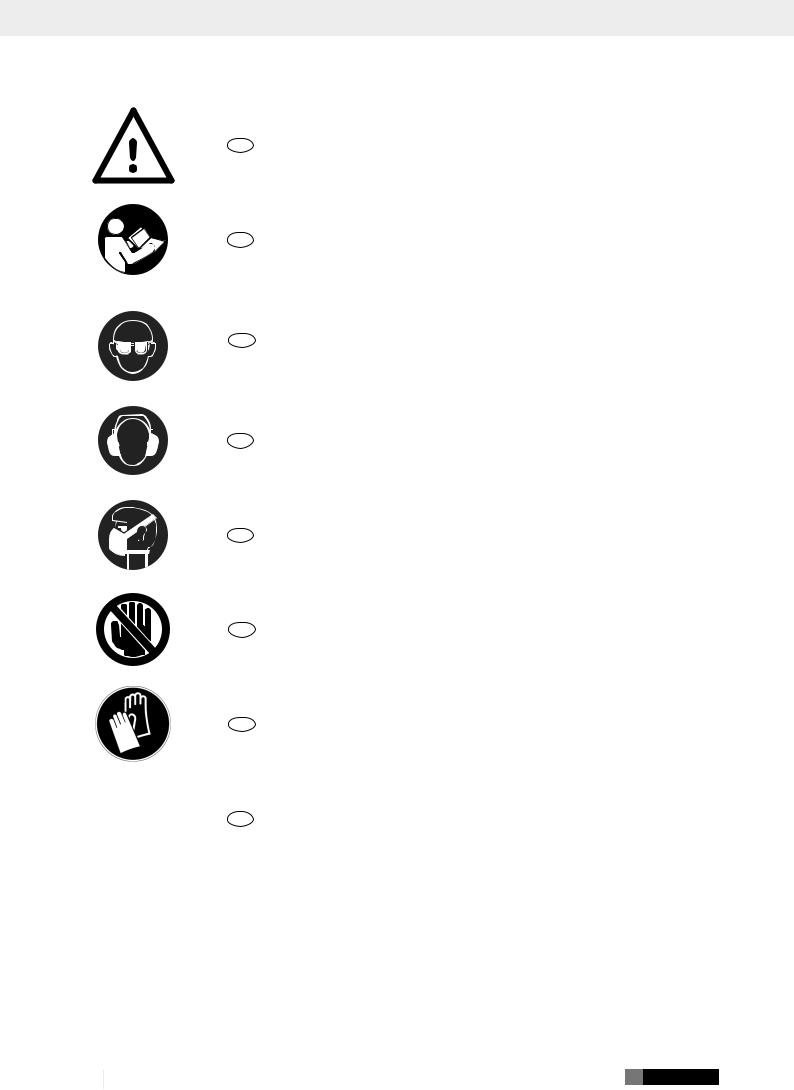
Explanation of the symbols on the equipment
|
|
|
|
|
GB |
WARNING: Failure to comply with may lead to danger to life, risk of injury or damage to |
|
|
|
|
|
the tool. |
|
|
|
|
|
|
|
|
|
|
|
|
|
|
|
|
|
|
|
|
|
|
|
|
|
|
|
GB |
Read instruction manual and safety instructions before starting up and pay attention to them. |
|
|
|
|
|
|
|
|
|
|
|
|
|
|
|
|
|
|
|
GB |
Wear safety goggles. |
|
|
|
|
|
|
|
|
|
|
|
|
|
|
|
|
|
|
|
GB |
Wear ear-muffs. |
|
|
|
|
|
||
|
|
|
||||
|
|
|
|
|
|
|
|
|
|
|
|
|
|
|
|
|
|
|
GB |
Wear a dust mask. |
|
|
|
|
|
|
|
|
|
|
|
|
|
|
|
|
|
|
|
GB |
IMPORTANT: Risk of injury! Never reach into the running saw blade. |
|
|
|
|
|
|
|
|
|
|
|
|
|
|
|
|
|
|
|
GB |
Wear work gloves. |
|
|
|
|
|
|
|
|
|
|
|
|
|
|
|
|
|
|
|
GB |
Protection class II (double shielded) |
|
|
|
|
|
||
|
|
|
|
|
||
|
|
|
|
|
|
|
|
|
|
|
|
|
|
|
|
|
|
|
|
|
2 GB

1. Introduction
Manufacturer: scheppach
Fabrikation von Holzbearbeitungsmaschinen GmbH Günzburger Straße 69
D-89335 Ichenhausen
Dear customer,
We hope your new tool brings you much enjoyment and success.
Note:
According to the applicable product liability laws, the manufacturer of the device does not assume liability for damages to the product or damages caused by the product that occurs due to:
•Improper handling
•Non-compliance of the operating instructions
•Repairs by third parties, by not authorized service technicians
•Installation and replacement of non-original spare parts
•Application other than specified
•A breakdown of the electrical system that occurs due to the non-compliance of the electric regulations and VDE regulations 0100, DIN 57113 / VDE0113
Please observe the following:
Read through the complete text in the operating instructions before installing and commissioning the device.
The operating instructions are intended to help the user to become familiar with the machine and take advantage of its application possibilities in accordance with the recommendations. The operating instructions contain important information on how to operate the machine safely, professionally and economically, how to avoid danger, costly repairs, reduce downtimes and how to increase reliability and service life of the machine. In addition to the safety regulations in the operating instructions, you have to meet the applicable regulations that apply for the operation of the machine in your country.
Keep the operating instructions package with the machine at all times and store it in a plastic cover to protect it from dirt and moisture. Read the instruction manual each time before operating the machine and carefully follow its information.
The machine can only be operated by persons who were instructed concerning the operation of the machine and who are informed about the associated dangers. The minimum age requirement must be complied with.
In addition to the safety instructions contained in this operating manual and the specific regulations of your country, the technical rules generally accepted for the operation of machines of the same type must be observed.
We accept no liability for damage or accidents which arise due to non-observance of these instructions and the safety information.
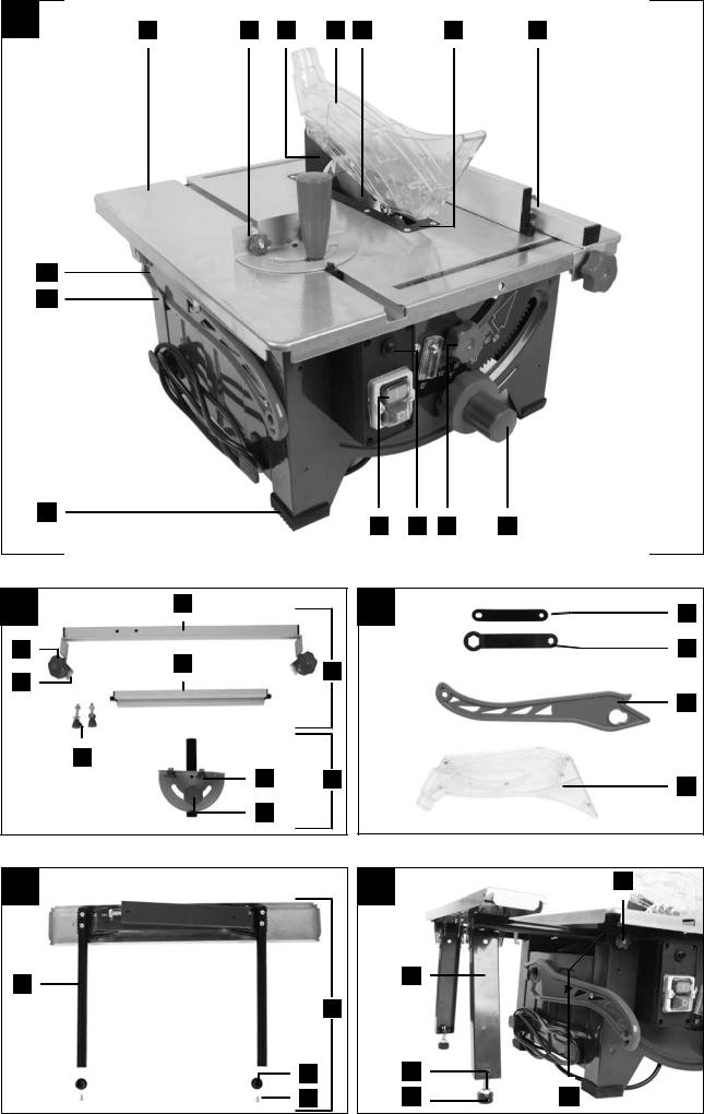
2. Device description (fig. 1-18, 24)
1.Saw table
2.Transverse stop
3.Riving knife
4.Saw blade guard
4a. Screw (saw blade guard)
5.Saw blade
6.Table inlay
7.Parallel stop, complete
8.Hand wheel
9.Locking handle
10.Overload switch
11.On/off switch
12.Rubber foot
13.Tool hook
14.Push stick
15.Locking knob
15a. Clamping plate
16. Holder
16a. Screw (parallel stop)
17.Stop rail
18.Knurled screw (transverse stop)
19.Turning handle
20.Ring spanner, 7/8 mm
21.Ring spanner, 19/10 mm
22.Table width extension
23.Guide tube
24.End piece
25.Screw (end piece)
26.Knurled screw (table width extension)
27.Guide bushing
28.Height adjustment screw
29.Lock nut
30.Support foot
31.Hole (riving knife)
32.Screw (table inlay)
33.Fixing screw (riving knife)
34.Screw (saw blade cover)
35.Saw blade cover
36.Suction port
37.Groove (stop rail)
38.Scale
39.Groove (stop rail)
40.Groove (saw table)
41.Mains cable
42.Bracket for workbench mounting
43.Screw (self-tapping)
44.Washers
GB 3

3. Scope of delivery
•Saw blade guard
•Push stick
•Parallel stop
•Transverse stop
•Table width extension
•End pieces and screws for table width extension
•Assembly material
•Ring spanner, 19/10 mm
•Ring spanner, 7/8 mm
•Operating manual
4. Intended use
The circular table saw is used for the longitudinal and transverse cutting (only with the transverse stop) of all types of timbers and plastic, in accordance with the machine size. It is not permitted to cut any type of round timber.
The equipment is allowed to be used only for its prescribed purpose. Any other use is deemed to be a case of misuse. The user/operator and not the manufacturer will be liable for any damage or injuries of any kind resulting from such misuse.
The machine is to be operated only with suitable saw blades. (HM or CV saw blades). The use of any type of HSS saw blades and cutting discs is prohibited.
An element of the intended use is also the observance of the safety instructions, as well as the assembly instructions and operating information in the operating manual.
Persons who operate and maintain the machine must be familiar with the manual and must be informed about potential dangers.
In addition, the applicable accident prevention regulations must be strictly observed.
Other general occupational health and safety-related rules and regulations must be observed.
m IMPORTANT
When using the equipment, a few safety precautions must be observed to avoid injuries and damage. Please read the complete operating instructions and safety regulations with due care. Keep this manual in a safe place, so that the information is available at all times. If you give the equipment to any other person, hand over these operating instructions and safety regulations as well. We cannot accept any liability for damage or accidents which arise due to a failure to follow these instructions and the safety instructions.
The manufacturer shall not be liable for any changes made to the machine nor for any damage resulting from such changes.
Despite use as intended, specific risk factors cannot be entirely eliminated. Due to the design and layout of the machine, the following risks remain:
•Contact with the saw blade in the exposed sawing area
•Reaching into the running saw blade (cutting injury)
•Kick-back of workpieces and workpiece parts
•Saw blade breakage
4 GB
•Ejection of faulty carbide parts of the saw blade
•Hearing damage when the necessary hearing protection is not used
•Harmful emissions of wood dusts during use in enclosed areas
Please note that our equipment has not been designed for use in commercial, trade or industrial applications. Our warranty will be voided if the equipment is used in commercial, trade or industrial businesses or for equivalent purposes.
5. Safety information
General power tool safety warnings
m WARNING: Read all safety warnings, instructions, illustrations and technical data provided with this power tool. Failure to follow the warnings and instructions may result in electric shock, fire and/or serious injury.
Save all warnings and instructions for future reference.
The term “power tool” in the warnings refers to your mainsoperated (corded) power tool or battery-operated (cordless) power tool.
1) Work area safety
a)Keep work area clean and well lit. Cluttered or dark areas invite accidents.
b)Do not operate power tools in explosive atmospheres, such as in the presence of flammable liquids, gases or dust. Power tools create sparks which may ignite the dust or fumes.
c)Keep children and bystanders away while operating a power tool. Distractions can cause you to lose control.
2) Electrical safety
a)Power tool plugs must match the outlet. Never modify the plug in any way. Do not use any adapter plugs with earthed (grounded) power tools. Unmodified plugs and matching outlets will reduce risk of electric shock.
b)Avoid body contact with earthed or grounded surfaces, such as pipes, radiators, ranges and refrigerators. There is an increased risk of electric shock if your body is earthed or grounded.
c)Do not expose power tools to rain or wet conditions. Water entering a power tool will increase the risk of electric shock.
d)Do not abuse the cord. Never use the cord for carrying, pulling or unplugging the power tool. Keep cord away from heat, oil, sharp edges or moving parts. Damaged or entangled cords increase the risk of electric shock.
e)When operating a power tool outdoors, use an extension cord suitable for outdoor use. Use of a cord suitable for outdoor use reduces the risk of electric shock.
f)If operating a power tool in a damp location is unavoidable, use a residual current device (RCD) protected supply. Use of an RCD reduces the risk of electric shock.
3) Personal safety
a)Stay alert, watch what you are doing and use common sense when operating a power tool. Do not use a power tool while you are tired or under the influence of drugs, alcohol or medication. A moment of inattention while operating power tools may result in serious personal injury.
b)Use personal protective equipment. Always wear eye protection. Protective equipment such as a dust mask, non-skid safety shoes, hard hat or hearing protection used for appropriate conditions will reduce personal injuries.
c)Prevent unintentional starting. Ensure the switch is in the off-position before connecting to power source and/or battery pack, picking up or carrying the tool. Carrying power tools with your finger on the switch or energising power tools that have the switch on invites accidents.
d)Remove any adjusting key or wrench before turning the power tool on. A wrench or a key left attached to a rotating part of the power tool may result in personal injury.
e)Do not overreach. Keep proper footing and balance at all times. This enables better control of the power tool in unexpected situations.
f)Dress properly. Do not wear loose clothing or jewellery. Keep your hair and clothing away from moving parts. Loose clothes, jewellery or long hair can be caught in moving parts.
g)If devices are provided for the connection of dust extraction and collection facilities, ensure these are connected and properly used. Use of dust collection can reduce dust-related hazards.
h)Do not let familiarity gained from frequent use of power tools allow you to become complacent and ignore power tool safety principles. A careless action can cause severe injury within a fraction of a second.
4) Power tool use and care
a)Do not force the power tool. Use the correct power tool for your application. The correct power tool will do the job better and safer at the rate for which it was designed.
b)Do not use the power tool if the switch does not turn it on and off. Any power tool that cannot be controlled with the switch is dangerous and must be repaired.
c)Disconnect the plug from the power source and/or remove the battery pack, if detachable, from the power tool before making any adjustments, changing parts of insert tools, or storing power tools. Such preventive safety measures reduce the risk of starting the power tool accidentally.
d)Store idle power tools out of the reach of children and do not allow persons unfamiliar with the power tool or these instructions to operate the power tool. Power tools are dangerous in the hands of untrained users.
e)Maintain power tools and insert tools. Check for misalignment or binding of moving parts, breakage of parts and any other condition that may affect the power tool’s operation. If damaged, have the power tool repaired before use. Many accidents are caused by poorly maintained power tools.
f)Keep cutting tools sharp and clean. Properly maintained cutting tools with sharp cutting edges are less likely to bind and are easier to control.
g)Use the power tool, accessories and tool bits etc. in accordance with these instructions, taking into account the working conditions and the work to be performed. Use of the power tool for operations different from those intended could result in a hazardous situation.
h)Keep handles and grasping surfaces dry, clean and free from oil and grease. Slippery handles and grasping surfaces do not allow for safe handling and control of the tool in unexpected situations.
Service
a)Have your power tool serviced by a qualified repair person using only identical replacement parts. This will ensure that the safety of the power tool is maintained.
m WARNING
This electric tool generates an electromagnetic field during operation. This field can impair active or passive medical implants under certain conditions. In order to prevent the risk of serious or deadly injuries, we recommend that persons with medical implants consult with their physician and the manufacturer of the medical implant prior to operating the electric tool.
Safety instructions for table saws
Guarding related warnings
a)Keep guards in place. Guards must be in working order and be properly mounted. A guard that is loose, damaged, or is not functioning correctly must be repaired or replaced.
b)Always use saw blade guard, riving knife and for every through–cutting operation. For throughcutting operations where the saw blade cuts completely through the thickness of the workpiece, the guard and other safety devices help reduce the risk of injury.
c)After completing working procedures where the removal of the protective cover and/or riving knife is necessary (e.g. producing folds and rebating, cutting grooves or cutting with a turnover), the protective system must be immediately reattached. The guard helps to reduce the risk of injury.
GB 5

d)Make sure the saw blade is not contacting the guard, riving knife or the workpiece before the switch is turned on. Inadvertent contact of these items with the saw blade could cause a hazardous condition.
e)Adjust the riving knife as described in this instruction manual. Incorrect spacing, positioning and alignment can make the riving knife ineffective in reducing the likelihood of kickback.
f)For the riving knife to work, they must be engaged in the workpiece. The riving knife are ineffective when cutting workpieces that are too short to be engaged with the riving knife. Under these conditions a kickback cannot be prevented by the riving knife.
g)Use the appropriate saw blade for the riving knife. For the riving knife to function properly, the saw blade diameter must match the appropriate riving knife and the body of the saw blade must be thinner than the thickness of the riving knife and the cutting width of the saw blade must be wider than the thickness of the riving knife.
Safety information for sawing
a)m DANGER: Do not place your hands and fingers in the sawing area or close to the saw blade.
A moment of carelessness or a slip could steer your hand towards the saw blade and result in serious injuries.
b)Only guide the workpiece against the rotational direction of the saw blade or cutting tool. Guiding the workpiece in the same direction as the rotational direction of the saw blade above the table can lead to the workpiece and your hand being drawn into the saw blade.
c)When performing longitudinal cuts, never use the mitre stop to guide the workpiece, and when transverse cutting with the mitre stop never additionally use the parallel stop for longitudinal adjustment. Simultaneously guiding the workpiece with the parallel stop and mitre stop increases the probability that the saw blade will jam and kickback will result.
d)When performing longitudinal cuts, always apply the feed force to the workpiece between the stop rail and the saw blade. Use a push rod if the distance between the stop rail and saw blade is less than 150 mm, and a push block if the distance is less than 50 mm. This type of working aid ensures that your hands remain a safe distance from the saw blade.
e)Only use the push rod provided by the manufacturer, or a push rod that has been produced in accordance with instructions. The push rod ensures a sufficient distance between the hand and saw blade.
f)Never use a damaged or partially sawn push rod. A damaged push rod may break and lead to your hand running into the saw blade.
g)Never work “freehand”. Always use the parallel stop or the mitre stop to position and guide the workpiece. “Freehand” means supporting or guiding the workpiece with the hands, rather than using the parallel stop or mitre stop.
6 GB
Free-handed sawing leads to incorrect alignment, jamming and kickback.
h)Never reach around or over a turning saw blade. Reaching for a workpiece can lead to accidental contact with the rotating saw blade.
i)Support long and/or wide workpieces at the rear and/or side of the saw table, so that they remain horizontal. Long and/or wide workpieces tend to tilt at the edge of the saw table; this leads to a loss of control, jamming of the saw blade and kickback.
j)Guide the workpiece steadily and evenly. Do not bend or twist the workpiece. If the saw blade jams, switch off the electric tool immediately, unplug the mains plug and remedy the cause of the jam. If the saw blade is jammed by the workpiece, this can lead to kickback or block the motor.
k)Do not remove partially sawn material whilst the saw is running. Partially sawn material can stick between the saw blade and stop rail or in the protective cover, and may draw your fingers into the saw blade during removal. Switch the saw off and wait until the saw blade has come to a standstill, before removing the material.
l)For longitudinal cuts on workpieces that are thinner than 2 mm, use an additional parallel stop that is in contact with the table surface. Thin workpieces can wedge under the parallel stop and lead to kickback.
Kickback - causes and corresponding safety instructions
Kickback is a sudden reaction of the workpiece to a catching or jamming saw blade, or a cut created in the workpiece at an angle to the saw blade, or if part of the workpiece becomes jammed between the saw blade and the parallel stop, or another stationary object.
In the majority of cases, with kickback the workpiece is caught by the rear part of the saw blade, lifted off the saw table and thrust in the direction of the operator. Kickback is the result of incorrect or deficient use of the circular table saw. It can be prevented by suitable precautionary measures, as described in the following.
a)Never stand directly in line with the saw blade. Always stand at the side of the saw blade on which the stop rail is located. With kickback, the workpiece may be thrust at high speed towards those persons who stand in front of, or in line with the saw blade.
b)Never reach over or behind the saw blade to pull or support the workpiece. This can result in accidental contact with the saw blade, or kickback can lead to your fingers being drawn into the saw blade.
c)Never hold and push the workpiece against the turning saw blade during sawing. Pushing the workpiece against the saw blade during sawing will lead to jamming and kickback.
d)Align the stop rail parallel to the saw blade.
A stop rail that is not aligned will push the workpiece against the saw blade and create kickback.

e)With concealed saw cuts (e.g. folds, grooves or slits in the turning process), use a thrust collar to guide the workpiece against the table and stop rail. Using a thrust collar, you are able to better control the workpiece in the event of kickback.
f)Apply particular caution when sawing assembled workpieces in areas that are not visible.
The plunging saw blade can saw into objects that could cause a kickback.
g)Support large panels, in order to avoid the risk of kickback due to a jammed saw blade. Large panels may bend under their own weight. Panels must be supported in all areas where they overhang the table surface.
h)Apply particular caution when sawing workpieces that are twisted, knotted or warped, or that do not have a straight edge that can be used to guide them with a mitre stop or along a stop rail. A twisted, knotted or warped workpiece is unstable and results in incorrect alignment of the kerf with the saw blade, jamming and kickback.
i)Never saw multiple workpieces stacked on top of each other, or one behind the other. The saw blade could engage in one or more parts and result in kickback.
j)If you wish to restart a saw, the saw blade of which is inserted in a workpiece, centre the saw blade in the sawing gap so that the saw teeth are not hooked in the workpiece. If the saw blade is jammed, it can lift the workpiece and cause kickback when the saw is restarted.
k)Always keep saw blades clean, sharp and sufficiently set. Never use warped saw blades or saw blades with cracked or broken teeth. Sharp and correctly set saw blades minimise jamming, blocking and kickback.
Safety instructions for the operation of circular table saws
a)Switch off the circular table saw and disconnect it from the power supply before removing the table insert, changing the saw blade, implementing settings on the riving knife or the saw blade protective cover, and if the machine is left unattended. Precautionary measures serve to prevent accidents.
b)Never leave the circular table saw running unattended. Switch off the electric tool and do not leave it until it has come to a complete standstill. An unattended running saw poses an uncontrolled risk.
c)Set up the circular table saw in a location that is level and well ventilated, and where it can stand safely and remain balanced. The installation site must provide sufficient space for easily handling the size of your workpieces. Disorganised and unlit working areas, and uneven, slippery floors may lead to accidents.
d)Regularly remove chips and sawdust from beneath the saw table and/or from the dust extraction system. Accumulated sawdust is flammable and can self-ignite.
e)Secure the circular table saw. If a circular table saw is not secured correctly, it can move or topple.
f)Remove the adjustment tools, wood residues, etc. from the circular table saw before switching it on. Deflections and possible jams could be dangerous.
g)Always use the right size of saw blade and an appropriate location hole (e.g. diamondshaped or round). Saw blades that do not fit with the mounting parts of the saw will run out-of-centre and result in a loss of control.
h)Never use damaged or incorrect saw blade mounting materials, such as flanges, washers, screws or nuts. These saw blade mounting materials have been specially designed for your saw, for optimum performance and operational safety.
i)Never stand on the circular table saw and do not use it as a step stool. Serious injuries can arise if the electric tool topples or if you accidentally come into contact with the saw blade.
j)Make sure that the saw blade is mounted in the correct direction of rotation. Do not use grinding discs or wire brushes with the circular table saw. Incorrect assembly of the saw blade or the use of accessories that have not been recommended can result in serious injuries.
Safety instructions for handling saw blades
1.Only use tools which you know how to handle.
2.Pay attention to the maximum speed. The maximum speed stated on the tool being used must not be exceeded. Keep within the speed range if one is specified
3.Note the direction of rotation of the motor and saw blade.
4.Do not use any insertion tools with cracks. Sort out cracked insertion tools. Repairs are not permitted.
5.Clean grease, oil and water off of the clamping surfaces.
6.Do not use any loose reducing rings or bushes to reduce holes on circular saw blades.
7.Make sure that fixed reducer rings for securing the insertion tool have the same diameter and have at least 1/3 of the cutting diameter.
8.Make sure that fixed reducer rings are parallel to each other.
9.Handle the tools used with care. It is best to store these in their original packaging or special containers. Always wear protective gloves to improve your grip and further reduce the risk of injury.
10.Before using any of the tools, ensure that all protective devices are correctly attached.
11.Before use, ensure that all of the tools used by you full the technical requirements of this power tool and are properly attached.
12.The saw blade supplied should only be used for sawing wood and never for working metal.
13.Use the saw blade intended for the material to be processed.
GB 7

14.Use only a saw blade with a diameter that matches the specifications on the saw.
15.Use only saw blades that are marked with an equal or higher rotational speed than that marked on the power tool.
16.Use only saw blades recommended by the manufacturer which conform to EN 847-1, if intended for cutting wood or similar materials.
17.Wear suitable personal protective equipment, such as:
–hearing protection;
–protective gloves when handling saw blades.
18.Use only saw blades recommended by the manufacturer which conform to EN 847-1. Warning! When changing the saw blade, make sure that the cutting width is not smaller and the thickness of the saw blade is not greater than the thickness of the splitter.
19.When sawing wood and plastics, avoid overheating the saw teeth. Reduce the feed speed to avoid the plastic melting.
Residual Risks
This power tool has been constructed in accordance with the latest technology and the generally recognised safety regulations. Nevertheless, it is possible that individual residual risks may occur during operation.
•Electrical hazard if improper electrical connection cables are used.
•In addition, concealed residual risks may be present in spite of all the precautions that have been taken.
•Residual risks can be minimised by observing the „Safety instructions“ and „Use in accordance with the designated purpose“, as well as the operating instructions.
•Do not put any unnecessary stresses on the machine: excessive pressure during sawing will quickly damage the saw blade. This may result in a reduction in the performance of the machine, as well as a reduction in the cutting accuracy.
•Avoid switching the machine on by accident: when inserting the plug into the socket, the power button must not be pressed.
•Use the tool which is recommended in this manual. This will ensure the optimal performance of your saw.
•Keep your hands away from the working area when the machine is in operation.
•Before you carry out any adjustments or servicing work, turn the device off and remove the mains plug.
8 GB
6. Technical data
AC motor...................................................... |
|
220-240 V~ 50 Hz |
Power consumption.......................................... |
1200 Watt (S1*) |
|
................................................................... |
|
1500 Watt (S6 25%) |
Idle speed n |
0............................................................... |
4800 min-1 |
Hard metal saw blade........................... |
ø 210 x ø 30 x 2,6 mm |
|
Number of teeth........................................................................ |
24 |
|
Riving knife thickness........................................................ |
2.0 mm |
|
Min. size of workpiece W x L x H ................... |
10 x 50 x 1 mm |
|
Table size.............................................................. |
|
485 x 445 mm |
Table width extension.......................................... |
485 x 515 mm |
|
Table size max. ................................................... |
485 x 630 mm |
|
Cutting height max. 45°................................................... |
45 mm |
|
Cutting height max. 90°................................................... |
48 mm |
|
Tilting saw blade.......................................................... |
0-45° left |
|
Suction connection......................................................... |
ø 35 mm |
|
Weight................................................................... |
|
approx. 14 kg |
Machine size (with extension) |
|
|
W x L x H................................................. |
|
485 x 630 x 440 mm |
*S1: Continuous operation at constant load **S6 25% operating mode:
Continuous duty with intermittent loading (operating time 10 min.)
In order avoid impermissible overheating of the motor, the motor should be driven for only 25% of the operating time with the stipulated nominal power and must then continue to run with no load for the remaining 75% of the operating time.
Noise
The total noise values were determined in accordance with EN 62841.
Sound pressure level LpA |
............................................ 87.5 dB(A) |
Uncertainty KpA ...................................................................... |
3 dB |
Sound power level LWA............................................. |
100.5 dB(A) |
Uncertainty KWA ..................................................................... |
3 dB |
Wear hearing protection.
The effects of noise can cause a loss of hearing. Total vibration values (vector sum - three directions) determined in accordance with EN 62841.
NOTE: The specified device emissions values have been measured in accordance with a standardised test procedure and can be used for comparison of one electric tool with another.
The specified device emissions values can also be used for an initial estimation of the load.
WARNING: The noise emission values can vary from the specified values during the actual use of the electric tool, depending on the type and the manner in which the electric tool is used, and in particular the type of workpiece being processed. Implement measures to protect against noise nuisance. In doing so, take into account the complete working process, including the times when the electric tool is working without load or switched off.
Suitable measures include regular maintenance and care of the electric tool and the insertion tools, regular breaks as well as proper planning of the working process.

7. Before starting the equipment
•Open the packaging and remove the device carefully.
•Remove the packaging material as well as the packaging and transport bracing (if available).
•Check that the delivery is complete.
•Check the device and accessory parts for transport damage.
•If possible, store the packaging until the warranty period has expired.
m WARNING
The device and packaging materials are not toys! Children must not be allowed to play with plastic bags, film and small parts! There is a risk of swallowing and suffocation!
•The equipment must be securely installed, i.e. bolted down on a workbench, base frame or similar. Use the holes on the inner side of the frame legs for this.
•All covers and safety devices have to be properly fitted before the equipment is switched on.
•It must be possible for the blade to run freely.
•When working with wood that has been processed before, watch out for foreign bodies such as nails or screws, etc.
•Before you press the On/Off switch check that the saw blade is fitted correctly. Moving parts must run smoothly.
•Before you connect the equipment to the power supply make sure the data on the rating plate are identical to the mains data.
•Connect the equipment to a properly installed protective contact socket, with at least 16 A circuit breaker.
8. Assembling the equipment
m WARNING: Disconnect the mains power plug before maintaining, resetting or assembling the table saw.
8.1 Before assembling the equipment
•Place all parts supplied on a flat surface.
•Group equal parts.
NOTE:
•If compounds with a bolt (round head / or hexagon), hex nuts and washers are backed up, the washer must be fitted under the nut.
•Insert screws each from outside to inside. Secure connections with nuts on the inside.
•Tighten the nuts and bolts during assembly only to the extent that they can not fall down. If you tighten the nuts and bolts prior to final assembly, final assembly can not be performed.
8.2 Fitting the table width extension (fig. 4-6)
1.Loosen the knurled screws (26) (fig. 5).
ATTENTION: Do not unscrew the knurled screws (26) too far.
2.Feed the guide tubes (23) of the table width extension (22) into the guide bushings (27) (see fig. 4/5).
3.Slide the end pieces (24) into the guide tubes (23) of the table width extension (22) as shown in fig. 6.
4.Fasten the end pieces (24) with the screws (25) as shown in Fig. 6.
5.Pull the table width extension (22) out completely and fasten in place with the knurled screws (26) (Fig. 5).
6.Now fold out the support feet (30).
7.Align the table width extension (22) horizontally with the table saw.
8.Loosen the lock nuts (29) on the respective support foot
(30)and adjust the height adjustment screw (28) as required.
9.Then retighten the lock nuts (29).
If you do not need the table width extension (22), fold the support feet (30) in.
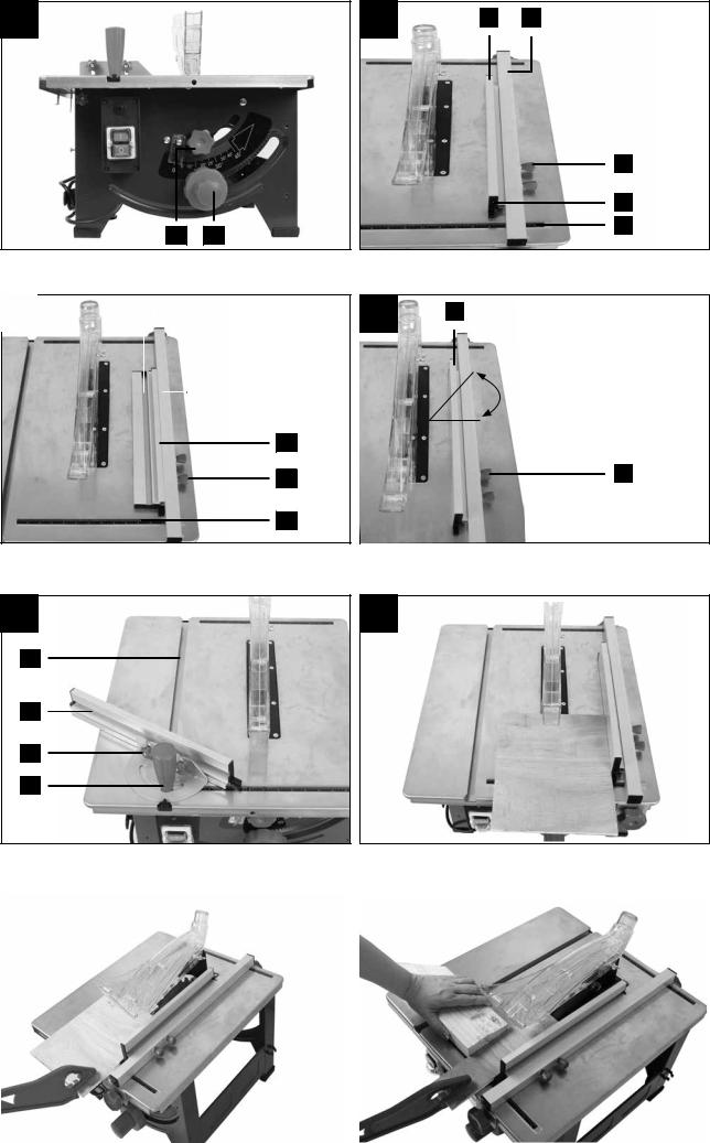
8.3 Fitting/removing the saw blade guard (fig. 7)
1.Place the saw blade guard (4) together with the screw (4a) on the riving knife (3) from above, so that the screw sits firmly in the hole of the riving knife (31).
2.Do not over-tighten the screw (4a). The saw blade guard
(4) must remain free to move.
3.Disassembly takes place in reverse order.
m WARNING: Before starting sawing, the saw blade guard (4) must be lowered onto the material to be sawn.
After fitting, check that the saw blade guard (4) is functioning properly. Lift the saw blade guard and then release it. The saw blade guard should automatically move back to its starting position.
8.4 Removing/fitting the table inlay (fig. 8)
m WARNING: In the event of wear or damage the table insert (6) must be replaced; otherwise there is an increased danger of injury.
1.Move the saw blade into the bottom position (see 9.2).
2.Take off the saw blade guard (4).
3.Remove the table insert screws (32).
4.Remove the table insert (6).
5.Installation of the table insert (6) takes place in reverse order.
8.5 Setting the riving knife (fig. 9) m WARNING: Pull out the mains plug.
m WARNING: The setting of the saw blade (5) must be checked after every saw blade replacement.
1.Set the saw blade (5) to the max. cutting depth, move to the 0° position and lock in place (see 9.2).
2.Remove the saw blade guard (4) (see 8.3).
3.Remove the table inlay (6) (see 8.4).
4.Loosen the fastening screws (33)
5.Align the riving knife (3) such that
a)the distance between the saw blade (5) and the splitter
(3)is max. 5 mm (fig. 10) and
b)the saw blade (5) is parallel to the splitter (3).
6.Retighten the fastening screws (33) and fit the table insert
(6) (see 8.4).
7.Fit the saw blade guard (4) again (see 8.3).
GB 9

8.6 Fitting/replacing the saw blade (fig. 11, 12) m WARNING: Pull out the mains plug and wear protective gloves.
1.Remove the saw blade guard (4) (see 8.3).
2.Unscrew the screws (34) on the bottom saw blade cover (35) and open it out.
3.Loosen the nut by applying the 19 mm ring spanner (21) to the nut and holding the motor shaft in place with an 8 mm ring spanner (20) (see fig. 12).
ATTENTION: Turn the nut in the direction of rotation of the saw blade.
4.Take off the outer flange and pull the old saw blade down and off the inner flange at an angle.
5.Clean the saw blade flange carefully with a wire brush before installing the new saw blade.
6.Insert the new saw blade in the reverse sequence and tighten.
m WARNING: Pay attention to the running direction. The cutting angle of the teeth must point in the running direction, i.e. forwards (see arrow on the saw blade guard (4)).
7.Close the bottom saw blade cover (35) and tighten the screws (34) again.
8.Refit the saw blade guard (4) and adjust it (see 8.3).
m WARNING: Check the protective devices before working with the saw again.
8.7 Fitting the parallel stop (fig, 2, 15)
1.Fasten the holder (16) to the table with the help of the locking knobs (15) and the clamping plates (15a).
2.Make sure that the holder (16) is aligned parallel to the saw blade (5). If necessary, readjust it with the aid of the scale (38).
3.Slide the sliding block along the groove (37) in the stop rail (17).
4.Fasten the stop rail (17) to the holder (16) with the help of the screws (16a).
8.8 Fitting the transverse stop (fig. 18)
1.Slide the transverse stop (2) in the groove (40) of the saw table (1).
2.Loosen the turning handle (19).
3.Turn the transverse stop (2) until the arrow points to the desired angle.
4.Retighten the turning handle (19).
8.9 Chip extraction (fig. 13)
ATTENTION: Only operate the device with an extraction system.
Connect a suitable chip extraction system (not included in the scope of delivery) to the suction port (36).
ATTENTION: Check and clean the suction channels at regular intervals.
10 GB
8.10 Stable fastening (fig. 25)
The machine must be securely installed, i.e. bolted down on a workbench, machine stand or similar, as shown in fig. 25. Use the bracket for workbench mounting (42), the screws (43) and the washers (44) to do so.
9. Handling the equipment
9.1 Switches (fig. 1)
9.1.1 On/off switch (11)
•It is possible to switch the saw on by pressing the green “I” button. Before starting sawing, wait until the saw blade has reached its maximum speed.
•In order to switch the saw off again, it is necessary to press the red “0” button.
9.1.2 Overload switch (10)
The device motor is protected against overload with an overload switch (10).
In the event of the nominal current being exceeded, the overload switch (10) switches the device off.
If this happens, proceed as follows:
•Let the device cool down for several minutes.
•Press the overload switch (10).
•Switch the device on by pressing the green “I” button.
9.2 Setting the cutting depth (fig. 1)
The saw blade (5) can be adjusted to the required cutting depth by turning the hand wheel (8).
•Counter-clockwise: Greater cutting depth
•Clockwise: Smaller cutting depth
Check the setting with a test cut.
9.3 Setting the angle (fig. 14)
Angled cuts of 0°-45° to the left of the parallel stop (7) can be carried out with the circular table saw.
m Before making every cut, check that no collision can occur between the stop rail (17), transverse stop (2) and the saw blade (5).
1.Loosen the locking handle (9).
2.Set the desired angle on the scale by turning the hand wheel
(8).
3.Lock the locking handle (9) at the desired angle setting.
9.4 Using the parallel stop (fig. 2, 15-17)
9.4.1 Stop heights (fig. 15, 16)
•The stop rail (17) of the parallel stop (7) has two guide surfaces at different heights.
•Depending on the thickness of the material to be cut, the stop rail (17) must be used as shown in Fig. 15 for thick material (workpiece thickness exceeding 25 mm) and as shown in Fig. 16 for thin material (workpiece thickness below 25 mm).

9.4.2 Shifting the stop rail (fig. 15, 16)
1.In order to move the stop rail (17) to the lower guide surface, loosen the two screws (16a) to release the stop rail (17) from the holder (16).
2.Pull the stop rail (17) along the groove and out.
3.Turn the stop rail (17) and slide the sliding block along the second groove (39).
4.Shifting to the higher guide surface must be carried out in the same way.
9.4.3 Cutting width (fig. 15, 16)
•The parallel stop (7) must be used when cutting sections of wood lengthways.
•The parallel stop (7) can be mounted on both sides of the saw table (1).
•The parallel stop (7) can be set to the required dimension with the aid of the scale (38) on the saw table (1).
•Tighten the two locking knobs (15) to fasten the parallel stop
(7)in place.
•Perform a test cut to measure the width before cutting the real workpiece. In this way you avoid inaccuracies with the scale or the setting.
9.4.4 Setting the stop length (fig. 15, 17)
In order to avoid the material to be cut becoming jammed, the stop rail (17) can slide in a longitudinal direction.
Rule of thumb: The rear edge of the stop should intersect an imaginary line that starts roughly at the centre of the saw blade and runs to the rear at 45°:
1.Set the required cutting width.
2.Loosen the screws (16a) and slide the stop rail (17) far enough forward that it touches the imaginary 45° line.
3.Tighten the screws (16a) again.
9.5 Using the transverse stop (fig. 18)
When trimming, the transverse stop (2) must be extended from the parallel stop (7) with the stop rail (17) (fig. 18).
9.5.1 Extending the transverse stop
1.Remove the stop rail (17) from the parallel stop (7). To do so, loosen the screws (16a) and release the stop rail (17) from the holder (16).
2.Slide the sliding block along the groove in the stop rail
3.Fasten the stop rail (17) with the help of the knurled screws
(18)on the transverse stop (2).
ATTENTION
Do not push the stop rail (17) too far toward to the saw blade
(5). The distance between the stop rail (17) and the saw blade
(5) should be approx. 2 cm.
10.Using the equipment
Working instructions
•After each new adjustment it is advisable to carry out a trial cut in order to check the set dimensions.
•After switching on the saw, wait for the blade to reach its maximum speed of rotation before commencing with the cut.
•Take extra care when starting the cut.
•Never use the equipment without the suction function.
• Regularly check and clean the suction channels.
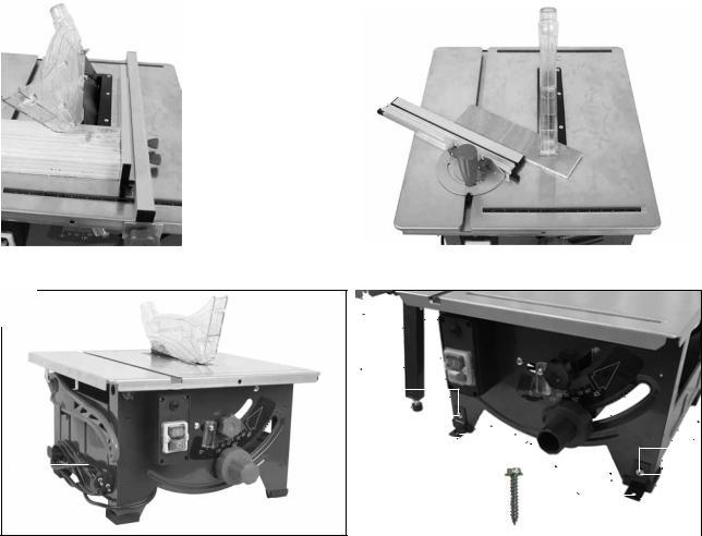
10.1 Making longitudinal cuts (fig. 19)
Longitudinal cutting is when you use the saw to cut along the grain of the wood. One edge of the workpiece will be pressed against the parallel stop (7), while the flat side lies on the saw table (1).
The saw blade guard (4) must always be lowered over the workpiece. When making a longitudinal cut, never adopt a working position that is in line with the cutting direction.
1.Set the parallel stop (7) in accordance with the workpiece height and the desired width (see 9.4).
2.Switch on the saw.
3.Place your hands (with fingers closed) flat on the workpiece and push the workpiece along the parallel stop (7) and into the saw blade (5).
4.Guide at the side with your left or right hand (depending on the position of the parallel stop) only as far as the front edge of the saw blade guard (4).
5.Always push the workpiece through to the end of the splitter (3).
6.The offcut piece remains on the saw table (1) until the saw blade (5) is back in its position of rest.
7.Secure long workpieces against falling off at the end of the cut (e.g. with a roller stand etc.).
ATTENTION: The parallel stop must be set parallel with the saw blade (see 8.7). Check the alignment and ensure that the parallel stop is firmly seated at regular intervals, particularly during use and after longer periods not in use. Tighten the screw again and adjust the parallel stop (see 9.4.3) if necessary. Vibrations can loosen screws and change the position of the parallel stop.
10.1.1 Cutting narrow workpieces (fig. 20)
Be sure to use a push stick (14) when making longitudinal cuts in workpieces smaller than 120 mm in width. A push stick (14) is supplied with the saw! Replace a worn or damaged push stick immediately.
1.Adjust the parallel stop (7) to the width of workpiece you require (see 9.4).
2.Feed in the workpiece with two hands. Always use the push stick (14) in the area of the saw blade.
3.Always push the workpiece through to the end of the splitter (3).
m WARNING: With short workpieces, use the push stick (14) from the beginning.
10.1.2Cutting extremely narrow workpieces (fig. 21)
Be sure to use a push block when making longitudinal cuts in very narrow workpieces with a width of 30 mm and less. There is no push block supplied with the saw! (Available from your specialist dealer) Replace the push block without delay when it becomes worn.
When sawing workpieces, these can become jammed between the parallel stop and the saw blade, be caught by the saw blade, and be thrown from the machine. Therefore, the low guide face of the parallel stop is best used in this case (see fig. 16). If required, change over the stop rail (see 9.4.2).
GB 11

1.Adjust the parallel stop to the width of workpiece you require.
2.Use the push block to press the workpiece against the stop rail and push the workpiece with the push stick (14) through to the end of the splitter.
10.1.3 Making angular cuts (fig. 22)
Angular cuts must always be made using the parallel stop (7). The parallel stop (7) must always be fitted to the right of the saw blade. Otherwise, workpieces can become jammed between the parallel stop and the saw blade during sawing and ejected at speed.
1.Set the saw blade (5) to the desired angle (see 9.3).
2.Set the parallel stop (7) in accordance with the workpiece width and height (see 9.4).
3.Carry out the cut in accordance with the workpiece width (see 10.1).
10.2 Making transverse cuts (fig. 23)
1.Push the transverse stop (2) into the groove (40) of the saw table and set it to the required angle (see 9.5).
2.Use the stop rail (17).
3.Press the workpiece firmly against the transverse stop (2).
4.Switch on the saw.
5.Push the transverse stop (2) and the workpiece toward the saw blade (5) in order to make the cut.
m WARNING: Always hold the guided part of the workpiece. Never hold the part which is to be cut off.
6.Push the transverse stop (2) forward until the workpiece is cut all the way through.
7.Switch off the saw again.
8.Do not remove the offcut until the saw blade has stopped rotating.
10.3 Cutting particle boards
To prevent the cutting edges from cracking when working with particle boards, you should not set the saw blade (5) more than 5 mm greater than the thickness of the workpiece (also see 9.2).
11.Transporting the equipment (fig. 24)
•Turn off the power tool before any transport and disconnect it from the power supply.
•Lower the saw blade (5) as far as possible.
•Wind up the mains cable (41).
•Carry the power tool with both hands by the fixed saw table
(1). Never use the table width extension to carry the power tool.
•Protect the power tool from knocks, bumps and strong vibrations, such as during transport in vehicles.
•Secure the power tool against overturning and sliding.
•Never use the safety devices for handling or transporting purposes.
12 GB
12.Maintaining the equipment
m WARNING: Prior to any adjustment, maintenance or service work disconnect the mains power plug!
12.1 General maintenance measures
•Keep protective devices, air vents, suction openings and the motor housing as free of dust and dirt as possible. Remove shavings and dust with a vacuum cleaner and a brush. In addition, blow it out with low-pressure compressed air.
•We recommend that you clean the equipment immediately after you use it.
•Clean the equipment regularly with a damp cloth and some soft soap. Do not use cleaning agents or solvents; these may be aggressive to the plastic parts in the equipment. Ensure that no water can get into the interior of the equipment.
•In order to extend the service life of the tool, oil the rotary parts once monthly. Do not oil the motor.
12.2 Carbon brushes
•In case of excessive sparking, have the carbon brushes checked only by an electrical specialist.
IMPORTANT: The carbon brushes must not be replaced by anyone but an electrical specialist.
Service information
Please note that the following parts of this product are subject to normal or natural wear and that the following parts are therefore also required for use as consumables.
Wear parts*: carbon brushes, table inlay, push stick, saw blade
* Not necessarily included in the scope of delivery!
13.Storing the equipment
Store the device and its accessories in a dark, dry and frostproof place that is inaccessible to children. The optimum storage temperature is between 5 and 30˚C.
Store the electrical tool in its original packaging.
Cover the electrical tool in order to protect it from dust and moisture.
Store the operating manual with the electrical tool.
14.Electrical connection
The electrical motor installed is connected and ready for operation. The connection complies with the applicable VDE and DIN provisions. The customer‘s mains connection as well as the extension cable used must also comply with these regulations.
Important information
In the event of an overloading the motor will switch itself off. After a cool-down period (time varies) the motor can be switched back on again.

Damaged electrical connection cable
The insulation on electrical connection cables is often damaged.
This may have the following causes:
•Passage points, where connection cables are passed through windows or doors
•Kinks where the connection cable has been improperly fastened or routed
•Places where the connection cables have been cut due to being driven over
•Insulation damage due to being ripped out of the wall outlet
•Cracks due to the insulation ageing
Such damaged electrical connection cables must not be used and are life-threatening due to the insulation damage.
Check the electrical connection cables for damage regularly. Make sure that the connection cable does not hang on the power network during the inspection.
Electrical connection cables must comply with the applicable VDE and DIN provisions. Only use connection cables with the marking “H05VV-F”.
The printing of the type designation on the connection cable is mandatory.
If it is necessary to replace the connection cable, this must be done by the manufacturer or their representative to avoid safety hazards.
AC motor:
•The mains voltage must be 220-240 V~.
•Extension cables up to 25 m length must have a cross section of 1.5 mm2.
Connections and repairs of electrical equipment may only be carried out by an electrician. Please provide the following information in the event of any enquiries:
•Type of current for the motor
•Machine data - type plate
•Motor data - type plate
15.Disposal and recycling
The equipment is supplied in packaging to prevent it from being damaged in transit. The raw materials in this packaging can be reused or recycled.
The equipment and its accessories are made of various types of material, such as metal and plastic. Defective components must be disposed of as special waste. Ask your dealer or your local council.
The packaging is wholly composed of environmentally-friendly materials that can be disposed of at a local recycling centre.
Contact your local refuse disposal authority for more details of how to dispose of your worn-out electrical devices.
Old devices must not be disposed of with household waste!
This symbol indicates that this product must not be disposed of together with domestic waste in compliance with the Directive (2012/19/EU) pertaining to waste electrical and electronic equipment (WEEE). This prod-
uct must be disposed of at a designated collection point. This can occur, for example, by handing it in at an authorised collecting point for the recycling of waste electrical and electronic equipment. Improper handling of waste equipment may have negative consequences for the environment and human health due to potentially hazardous substances that are often contained in electrical and electronic equipment. By properly disposing of this product, you are also contributing to the effective use of natural resources. You can obtain information on collection points for waste equipment from your municipal administration, public waste disposal authority, an authorised body for the disposal of waste electrical and electronic equipment or your waste disposal company.
GB 13

16.Troubleshooting
Fault |
Possible causes |
Action |
|
|
|
Blade dissolves after |
To slightly tightened fastening nut |
Tighten the right hand thread nut |
switching off the engine |
|
|
|
|
|
Engine will not start |
Failure mains fuse |
Check mains fuse |
|
|
|
|
Defective extension cable |
Replace extension cord |
|
|
|
|
Connections on motor or switch not in order |
Repair by electrical specialist |
|
|
|
|
Motor or switch faulty |
Repair by electrical specialist |
|
|
|
Motor will not work, the |
Cross section of the extension cable is not |
See „Electrical connection“ |
fuse is active |
sufficient |
|
|
|
|
|
Overload by a blunt saw blade |
Change saw blade |
|
|
|
Fire marks on the cutting |
Blunt saw blade |
Have saw blade sharpened (only by an authorised |
surface |
|
sharpening specialist) or change it |
|
|
|
|
Wrong saw blade |
Change saw blade |
|
|
|
14 GB
17. Warranty certificate
Dear Customer,
All of our products undergo strict quality checks to ensure that they reach you in perfect condition. In the unlikely event that your device develops a fault, please contact our service department at the address shown on this guarantee card. Of course, if you would prefer to call us then we are also happy to offer our assistance under the service number printed below. Please note the following terms under which guarantee claims can be made:
•These guarantee terms cover additional guarantee rights and do not affect your statutory warranty rights. We do not charge you for this guarantee.
•Our guarantee only covers problems caused by material or manufacturing defects, and it is restricted to the rectification of these defects or replacement of the device. Please note that our devices have not been designed for use in commercial, trade or industrial applications. Consequently, the guarantee is invalidated if the equipment is used in commercial, trade or industrial applications or for other equivalent activities. The following are also excluded from our guarantee: compensation for transport damage, damage caused by failure to comply with the installation/assembly instructions or damage caused by unprofessional installation, failure to comply with the operating instructions (e.g. connection to the wrong mains voltage or current type), misuse or inappropriate use (such as overloading of the device or use of non-approved tools or accessories), failure to comply with the maintenance and safety regulations, ingress of foreign bodies into the device (e.g. sand, stones or dust), effects of force or external influences (e.g. damage caused by the device being dropped) and normal wear resulting from proper operation of the device.
The guarantee is rendered null and void if any attempt is made to tamper with the device.
•The guarantee is valid for a period of 3 years starting from the purchase date of the device. Guarantee claims should be submitted before the end of the guarantee period within two weeks of the defect being noticed. No guarantee claims will be accepted after the end of the guarantee period. The original guarantee period remains applicable to the device even if repairs are carried out or parts are replaced. In such cases, the work performed or parts fitted will not result in an extension of the guarantee period, and no new guarantee will become active for the work performed or parts fitted. This also applies when an on-site service is used.
•In order to assert your guarantee claim, please contact the service partner shown below. If the complaint is within the guarantee period, we will provide you with a return slip, with which you can return your defective device free of charge to us. It would help us if you could describe the nature of the problem in as much detail as possible. If the defect is covered by our guarantee then your device will either be repaired immediately and returned to you, or we will send you a new device.
Of course, we are also happy offer a chargeable repair service for any defects which are not covered by the scope of this guarantee or for units which are no longer covered. To take advantage of this service, please send the device to our service address.
Service-Hotline (GB):
+800 4003 4003
(0,00 EUR/Min.)
Service-Email (GB): service.GB@scheppach.com
Service Address (GB):
Forest Park & Garden
Coed Court, Taffsmead Road
Treforest, Ind. Estate, Pontypridd CF375SW
At www.lidl-service.com you can download this and many more manuals, product videos plus installation software.
The QR code takes you directly to the Lidl service page (www.lidl-service.com) and you can open your operating manual by entering the article number (IAN) 322850_1901.
GB 15

Tartalomjegyzék: |
Oldal: |
|
1. |
Bevezetés........................................................................................................................................................................................................... |
18 |
2. |
A készülék leírása (1-18, 24 ábra).................................................................................................................................................................. |
18 |
3. |
Szállított elemek................................................................................................................................................................................................. |
19 |
4. |
Rendeltetésszerűi használatg............................................................................................................................................................................ |
19 |
5. |
Biztonsági utasítások......................................................................................................................................................................................... |
19 |
6. |
Technikai adatok................................................................................................................................................................................................ |
24 |
7. |
Az üzembe helyezés előtt................................................................................................................................................................................. |
24 |
8. |
Felépítés.............................................................................................................................................................................................................. |
25 |
9. |
Kezelés............................................................................................................................................................................................................... |
26 |
10. |
Üzem.................................................................................................................................................................................................................. |
27 |
11. |
Szállítás (24 ábra)............................................................................................................................................................................................. |
28 |
12. |
Karbantartás...................................................................................................................................................................................................... |
28 |
13. |
Tárolás................................................................................................................................................................................................................ |
28 |
14. |
Elektromos csatlakoztatás................................................................................................................................................................................. |
28 |
15. |
Megsemmisítés és újrahasznosítás................................................................................................................................................................... |
29 |
16. |
Hibaelhárításe.................................................................................................................................................................................................... |
30 |
17. |
Jótállási tájékoztató........................................................................................................................................................................................... |
31 |
18. |
Megfelelőségi nyilatkozat................................................................................................................................................................................. |
95 |
16 HU
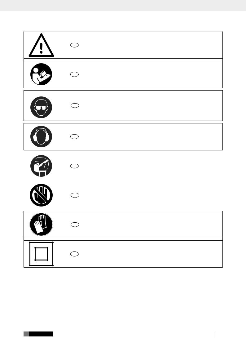
A készüléken található szimbólumok magyarázata
HU |
Figyelem! A használati utasítás be nem tartása életveszélyt, sérülésveszélyt vagy a szerszám |
|
károsodását idézheti elő! |
||
|
HU |
Üzembe helyezés előtt olvassa el és vegye figyelembe a kezelési útmutatót és a biztonsági |
|
utasításokat! |
||
|
HU |
Viseljen védőszemüveget! |
HU |
Viseljen hallásvédőt! |
HU |
Porképződés esetén viseljen megfelelő légzésvédőt! |
|
|
HU |
Figyelem! Sérülésveszély! Ne nyúljon a működő fűrészlaphoz! |
|
|
HU |
Viseljen védőkesztyűt! |
HU |
II. védelmi osztály (kettős szigetelés) |
HU 17

1. Bevezetés
Gyártó: scheppach
Fabrikation von Holzbearbeitungsmaschinen GmbH Günzburger Straße 69
D-89335 Ichenhausen
Tisztelt vásárló!
Sok örömet és sikert kívánunk Önnek, amikor az új készülékét használja.
Kedves Vásárló!
A hatályban lévő termékfelelősségi törvény értelmében a berendezés gyártója nem vonható felelősségre a berendezésen vagy vele kapcsolatban keletkező károkért a következő esetekben:
•szakszerűtlen kezelés,
•a használati utasítások be nem tartása,
•harmadik személy által végzett, szakképzetlen javítások,
•nem eredeti alkatrészek beszerelése és cseréje,
•szakszerűtlen használat,
•az elektromos rendszer kiesése az elektromos előírások, illetve a VDE 0100, DIN 57113 / VDE 0113 szabályozások be nem tartása miatt.
Javaslatok:
Mielőtt a berendezést összeszerelné, és üzembe helyezné olvassa el a használati útmutató teljes szövegét.
Az üzemelési utasítások célja a készülékkel való ismerkedésének megkönnyítése és a használati lehetőségeinek megismertetése.
Az üzemelési utasítások fontos megjegyzéseket tartalmaz a készülék biztonságos, szakszerű és gazdaságos használatával kapcsolatosan, a veszélyek elkerülésére, a javítási költségek megspórolására, a kiesési idő csökkentésére, és a készülék megbízhatóságának és élettartamának növelésére.
A használati útmutatóba foglalt biztonsági utasításokon kívül mindenképpen be kell tartani a nemzeti érvényben lévő szabályozásokat a készülék üzemelésével kapcsolatosan.
Az üzemelési utasításokat helyezze egy tiszta, műanyag mappába, hogy megóvja a szennyeződéstől és a nedvességtől, és tárolja a készülék közelében. A munka elkezdése előtt minden gépkezelőnek el kell olvasnia az utasításokat és gondosan be kell tartania őket.
Csak olyan személyek használhatják a készüléket, akiket kiképeztek a gép használatáról, és a lehetséges veszélyekről, illetve kockázatokról. Be kell tartani az előírt minimális kort.
A jelen kezelési útmutató biztonsági utasításain és országa speciális előírásain túl tartsa be az azonos kialakítású gépek üzemeltetésére vonatkozó általánosan elismert műszaki szabályokat is.
Az útmutató, valamint a biztonsági előírások figyelmen kívül hagyásából származó balesetekért és károkért nem vállalunk felelősséget.
18 HU
2. A készülék leírása (1-18, 24 ábra)
1.Fűrészasztal
2.Keresztütköző
3.Hasítóék
4.Fűrészlapvédő
4a. Csavar (fűrészlapvédő)
5.Fűrészlap
6.Asztalbetét
7.Párhuzamos ütköző, teljes
8.Kézikerék
9.Rögzítő fogantyú
10.Túlterhelés elleni kapcsoló
11.Be-/kikapcsoló
12.Gumiláb
13.Szerszámakasztó
14.Tolóbot
15.Rögzítőgomb
15a. |
Szorítólemez |
16. |
Tartó |
16a. |
Csavar (párhuzamos ütköző) |
17.Ütközősín
18.Recézett fejű csavar (keresztütköző)
19.Forgó markolat
20.Csillagkulcs, 7/8 mm
21.Csillagkulcs, 19/10 mm
22.Asztalszélesítő
23.Vezetőcső
24.Végdarab
25.Csavar (végdarab)
26.Recézett fejű csavar (asztalszélesítő)
27.Vezetőpersely
28.Magasságállító csavar
29.Ellenanya
30.Támasztóláb
31.Furat (hasítóék)
32.Csavar (asztalbetét)
33.Rögzítőcsavar (hasítóék)
34.Csavar (fűrészlap burkolata)
35.Fűrészlap burkolata
36.Elszívócsonk
37.Horony (ütközősín)
38.Skála
39.Horony (ütközősín)
40.Horony (fűrészasztal)
41.Hálózati kábel
42.Szögidom a műhelypad felszereléséhez
43.Csavar (önmetsző)
44.Alátétek

3. Szállított elemek
•Fűrészlapvédő
•Tolóbot
•Párhuzamos ütköző
•Keresztütköző
•Asztalszélesítő
•Végdarabok és csavarok az asztalszélesítőhöz
•Szerelőanyag
•Csillagkulcs, 19/10 mm
•Csillagkulcs, 8 mm
•Kezelési útmutató
4. Rendeltetésszerűi használatg
Az asztali körfűrész minden típusú fa és műanyag hosszés keresztirányú (csak keresztütközővel) vágására szolgál, a gépmérettől függően. Semmilyen fajta kör keresztmetszetű fát nem szabad vágni.
A gépet csak rendeltetése szerint szabad használni. Ezt túlhaladó bármilyen használat, nem számít rendeltetésszerűnek. Ebből adódó bármilyen kárért vagy bármilyen fajta sérülésért a használó ill. a kezelő felelős és nem a gyártó.
Csak a gépnek megfelelő fűrészlapokat (KFvagy CV-fűrészla- pokat) szabad használni. Tilos bármiljen fajta HSS – fűrészlapnak és szétválasztó tárcsának a használata.
A rendeltetésszerű használat része a biztonsági utasítások betartása, valamint a kezelési utasításban foglalt szerelési és üzemeltetési utasítások betartása is.
A gépet kezelő és karbantartó személyeknek ismerniük kell ezeket, és tájékozottnak kell lenniük a lehetséges veszélyekről. Ezenfelül a lehető legszigorúbban be kell tartani a baleset-meg- előzési előírásokat.
Vegye figyelembe a további általános érvényű munkaegészségügyi és biztonságtechnikai szabályokat is.
m FIGYELEM
A készülékek használatánál, a sérülések és a károk megakadályozásának az érdekében be kell tartani egy pár biztonsági intézkedést. Ezért ezt a használati utasítást/biztonsági utasításokat gondosan átolvasni. Őrizze ezeket jól meg, azért hogy mindenkor rendelkezésére álljanak az információk. Ha más személyeknek adná át a készüléket, akkor kérjük kézbesítse ki vele együtt ezt a használati utasítást/biztonsági utasításokat is. Nem vállalunk felelőséget olyan balesetekért vagy károkért, amelyek ennek az utasításnak és a biztonsági utasításoknak a figyelmen kívül hagyásából keletkeznek.
Ha a berendezésen változtatást hajt végre, az ebből eredő károkért a gyártó nem vállal felelősséget.
A rendeltetésszerű használat ellenére bizonyos kockázatok teljes egészében nem küszöbölhetők ki. A gép szerkezetéből és felépítéséből kifolyólag a következő kockázatok jelentkezhetnek:
•A fűrészlap megérintése a fedetlen fűrészelési területen
•A működő fűrészlapba történő benyúlás (vágási sérülés)
•A munkadarabok és a munkadarab részeinek visszacsapása
•A fűrészlap törése
•A fűrészlap hibás keményfém részeinek kivetése
•Halláskárosodás, ha nem használja a szükséges hallásvédőt.
•Zárt helyiségekben számolni kell a fapor egészségkárosító kibocsátásával.
Vegye figyelembe, hogy a készülékeink rendetetésszerűen nem ipari, szakmai vagy gyári alkalmazásra készültek. Nem vállalunk szavatosságot, ha a készüléket ipari-, szakmaigyárivagy ennek megfelelő tevékenységre használja.
5. Biztonsági utasítások
Az elektromos szerszámokra vonatkozó általános biztonsági utasítások
m FIGYELMEZTETÉS: Olvassa el az összes biztonsági utasítást, egyéb utasítást, ábrát és műszaki adatot, melyet az elektromos szerszámhoz mellékeltek.
A következő útmutatások betartásának elmulasztása áramütést, tüzet és/vagy súlyos sérüléseket okozhat.
Az összes biztonsági utasítást és útmutatót őrizze meg későbbi használat céljából.
A biztonsági utasításokban használt „elektromos szerszám” fogalom a hálózatról üzemeltetett elektromos szerszámokra (hálózati vezetékkel), illetve az akkumulátorról üzemeltetett elektromos szerszámokra (hálózati vezeték nélkül) vonatkozik.
1) A munkahely biztonsága
a)Gondoskodjon a munkahely tisztaságáról és megfelelő megvilágításáról. A rendetlenség, illetve a megvilágítatlan munkaterületek balesetekhez vezethetnek.
b)Ne dolgozzon az elektromos szerszámmal olyan robbanásveszélyes környezetben, ahol éghető folyadékok, gázok vagy porok találhatók. Az elektromos szerszámok szikráznak, és a szikrák meggyújthatják a port és a gőzöket.
c)Az elektromos szerszám használata során tartsa távol a gyermekeket és más személyeket. A figyelem elterelése miatt elveszítheti uralmát az elektromos szerszám felett.
2) Elektromos biztonság
a)Az elektromos szerszám csatlakozódugója illeszkedjen a csatlakozóaljzatba.
A csatlakozódugót semmilyen módon nem szabad módosítani. A védőföldeléssel ellátott elektromos szerszámokkal együtt ne használjon adapteres csatlakozót. A változatlan csatlakozódugók és a hozzájuk illő csatlakozóaljzatok csökkentik az áramütés kockázatát.
b)Kerülje el a teste földelt felületekkel, például csövekkel, fűtésekkel, tűzhelyekkel és hűtőszekrényekkel való érintkezését. Megnövekedik az áramütés kockázata, ha a teste földelve van.
HU 19

c)Tartsa esőtől és nedvességtől távol az elektromos szerszámokat.
Az elektromos szerszámba hatoló víz növeli az áramütés kockázatát.
d)Ne használja a csatlakozó vezetéket a rendeltetésétől eltérő módon, például az elektromos szerszám szállításához, felakasztásához vagy a csatlakozóaljzatból való kihúzásához. Tartsa távol a csatlakozó vezetéket hőtől, olajtól, éles élektől és a mozgó alkatrészeitől. A sérült vagy összegubancolódott csatlakozó vezeték növeli az áramütés kockázatát.
e)Ha a szabadban dolgozik az elektromos szerszámmal, akkor csak olyan hosszabbító vezetékeket alkalmazzon, amelyek kültéri használatra is alkalmasak. A kültéri használatra alkalmas hosszabbító vezeték használata csökkenti az áramütés kockázatát.
f)Ha elkerülhetetlen, hogy nedves környezetben használja az elektromos szerszámot, akkor használjon hibaáram-védőkapcsolót. A hibaá- ram-védőkapcsoló használata csökkenti az áramütés kockázatát.
3) Személyi biztonság
a)Legyen figyelmes, ügyeljen arra, amit csinál, és az elektromos szerszám használata során józan ésszel cselekedjen. Ne használja az elektromos szerszámot, ha fáradt, vagy ha drogok, alkohol vagy gyógyszerek hatása alatt áll. Az elektromos szerszám használata során egy pillanatnyi figyelmetlenség is súlyos sérüléseket okozhat.
b)Viseljen személyi védőfelszerelést, és mindig használjon védőszemüveget. Az elektromos szerszám típusától és használatától függően alkalmazott személyi védőfelszerelések, például pormaszk, csúszásmentes munkavédelmi cipő, munkavédelmi sisak vagy hallásvédő viselése csökkenti a sérülések kockázatát.
c)Kerülje el az akaratlan üzembe helyezést. A szerszám áramellátásra és/vagy akkumulátorra való csatlakoztatása, felvétele vagy szállítása előtt győződjön meg arról, hogy ki van-e kapcsolva az elektromos szerszám. Ha az elektromos szerszám szállítása közben a kapcsolón tartja az ujját, vagy a készüléket bekapcsolva csatlakoztatja az áramellátásra, akkor balesetek történhetnek.
d)Az elektromos szerszám bekapcsolása előtt távolítsa el a beállító szerszámokat vagy a csavarkulcsokat. Az elektromos szerszám forgó részében maradt szerszám vagy kulcs sérüléseket okozhat.
e)Kerülje a rendellenes testtartást. Álljon stabilan a lábán, és mindig őrizze meg egyensúlyát.
Így váratlan helyzetekben is jobban irányíthatja az elektromos szerszámot.
f)Megfelelő ruházatot viseljen. Ne viseljen túl bő ruházatot vagy ékszereket. Haját és ruházatát tartsa távol a maguktól mozgó alkatrészektől.
A mozgó alkatrészek elkaphatják a laza ruházatot, az ékszereket vagy a hosszú hajat.
20 HU
g)Ha lehetséges a porelszívó és -gyűjtő berendezések felszerelése, azokat csatlakoztatni és megfelelően használni kell. Porelszívó használatával csökkentheti a por által okozott veszélyeket.
h)Ne keltsen hamis biztonságérzetet és ne szegje meg az elektromos szerszámra vonatkozó biztonsági előírásokat még abban az esetben sem, ha az elektromos szerszámot többszöri használat után ismerni vélni. A másodperc törtrésze alatt bekövetkező súlyos sérülések lehetnek a következményei annak, ha a szerszámot gondatlanul kezeli.
4)Az elektromos szerszám használata és kezelése
a)Ne terhelje túl az elektromos szerszámot. Munkájához az ahhoz meghatározott elektromos szerszámot használja. A megfelelő elektromos szerszámmal jobban és biztonságosabban dolgozhat a megadott teljesítménytartományban.
b)Ne használjon olyan elektromos szerszámot, amelynek hibás a kapcsolója. Az az elektromos szerszám, amelyet nem lehet bevagy kikapcsolni, veszélyesnek számít, és meg kell javítani.
c)Húzza ki a csatlakozódugót a csatlakozóaljzatból, és/vagy vegye ki a kivehető akkumulátort, mielőtt beállításokat végez a készüléken, cserélhető szerszámokat cserél ki vagy félreteszi az elektromos szerszámot. Ezen elővigyázatossági intézkedések megakadályozzák az elektromos szerszám akaratlan elindulását.
d)A nem használt elektromos szerszámokat gyermekektől távol tárolja. Ne hagyja, hogy az elektromos szerszámot olyan személyek használják, akik nem ismerik azt vagy nem olvasták el a jelen utasításokat. Az elektromos szerszámok veszélyesek, ha tapasztalatlan személyek használják őket.
e)Gondosan ápolja az elektromos szerszámokat és a cserélhető szerszámot. Ellenőrizze, hogy a mozgó alkatrészek kifogástalanul működ- nek-e, nem szorulnak, nincsenek-e törött vagy sérült alkatrészek, amelyek negatív hatással lennének az elektromos szerszám működésére. Az elektromos szerszám használata előtt javíttassa meg a sérült alkatrészeket. Sok balesetet a rosszul karbantartott elektromos szerszámok okoznak.
f)Tartsa élesen és tisztán a vágószerszámokat.
A gondosan ápolt, éles vágóélekkel rendelkező vágószerszámok kevésbé szorulnak be, és könnyebben vezethetők.
g)Az elektromos szerszámot, tartozékokat, betétszerszámokat stb. a jelen utasításoknak megfelelően használja. Közben vegye figyelembe a munkafeltételeket és a végrehajtandó feladatot is. Az elektromos szerszámoknak a tervezett alkalmazásoktól eltérő használata veszélyes helyzetekhez vezethet.

h)A fogantyúkat és a fogantyúfelületeket mindig száraz, tiszta, valamint olajtól és zsírtól mentes állapotban kell tartani. A csúszós fogantyú és fogantyúfelületek nem teszik lehetővé az elektromos szerszám biztonságos üzemeltetését és afölötti uralmának megőrzését előre nem látható helyzetekben.
5) Szerviz
a)Csak képzett szakszemélyzettel és csak eredeti pótalkatrészek használatával javíttassa meg elektromos szerszámát. Ezáltal biztosítható az elektromos szerszám biztonságának megőrzése.
Figyelmeztetés!
Ez az elektromos kéziszerszám működés közben elektromágneses mezőt képez. Ez a mező bizonyos körülmények között befolyásolhatja az aktív és passzív orvosi implantátumok működését. A súlyos és halálos sérülések veszélyének csökkentése érdekében javasoljuk, hogy az orvosi implantátumokkal élő személyek az elektromos kéziszerszám kezelése előtt kérjék ki orvosuk és az implantátum gyártójának véleményét.
Az asztali körfűrészekre vonatkozó biztonsági utasítások
A védőburkolatokra vonatkozó biztonsági utasítások
a)Hagyja felszerelve a védőburkolatokat. A védőburkolatoknak működőképes és megfelelően felszerelt állapotban kell lenni.
A meglazult, sérült vagy nem megfelelően működő védőburkolatokat meg kell javítani vagy ki kell cserélni.
b)A daraboló vágásokhoz mindig használja a fűrészlap védőburkolatát és a hasítóéket.
Az olyan daraboló vágások esetén, amikor a fűrészlap teljes mértékben átfűrészeli a munkadarab vastagságát, a védőburkolat és az egyéb biztonsági berendezések csökkentik a sérülések kockázatát.
c)Azon munkafolyamatok (pl. szélezés, hornyolás vagy felsliccelés) befejezésekor, amelyekhez a védőburkolat és/vagy a hasítóék eltávolítására van szükség, befejezésekor azonnal helyezze vissza a védőrendszert.
A védőburkolat csökkenti a személyi sérülések kockázatát.
d)Az elektromos szerszám bekapcsolása előtt győződjön meg arról, hogy a fűrészlap nem ér a védőburkolathoz, a hasítóékhez vagy a munkadarabhoz.
Amennyiben ezek a komponensek véletlenül a fűrészlaphoz érnek, akkor az veszélyes helyzethez vezethet.
e)Állítsa be a hasítóéket a jelen üzemeltetési utasításban található leírásnak megfelelően. Ha helytelen a távolság, az elhelyezkedés vagy a beigazítás, annak az lehet a következménye, hogy a hasítóék nem tudja hatékonyan megakadályozni a visszacsapódást
f)Ahhoz, hogy a hasítóék működni tudjon, a munkadarabra kell hatást gyakorolnia. Az olyan munkadarabokban végzett vágások esetén, amelyek túl rövidek, a hasítóék nem képes kifejteni a hatását.
Ilyen feltételek mellett a hasítóék nem képes megakadályozni a visszacsapódást.
g)A hasítóékhez illő fűrészlapot használjon. Ahhoz, hogy a hasítóék megfelelően működjön, a fűrészlap átmérőjének illeszkednie kell a megfelelő hasítóékhez, a fűrészlap törzslapjának vékonyabbnak kell lennie a hasítóéknél, és a fogszélességnek nagyobbnak kell lennie a hasítóék vastagságánál.
A fűrészelési műveletre vonatkozó biztonsági utasítások
a)m VESZÉLY: Kezét és ujjait tartsa távol a fűrészlaptól és a fűrészelési tartománytól.
Egy pillanatnyi figyelmetlenség, vagy a munkadarab elcsúszása a fűrészlaphoz vezetheti a kezét, és súlyos sérüléseket okozhat.
b)A munkadarabot mindig a fűrészlap vagy a vágószerszám forgásirányával ellentétesen vezesse.
Ha a forgásiránnyal azonos irányban vezeti a munkadarabot a fűrészasztal felett a fűrészlaphoz, az azzal járhat, hogy a munkadarabot és a kezét berántja a fűrészlap.
c)Hosszanti vágásoknál soha ne használjon gérvágó ütközőt a munkadarab bevezetéséhez, és a gérvágó ütközővel végzett keresztirányú vágásoknál soha ne használja a párhuzamos ütközőt a hosszbeállításhoz. Ha egyszerre vezeti a munkadarabot a párhuzamos és a gérvágóütközővel, akkor megnő a valószínűsége, hogy a fűrészlap megszorul és visszacsap.
d)Hosszanti vágásnál mindig az ütközősínek és a fűrészlap között fejtsen ki előtoló erőt a munkadarabra. Használjon tolófát, ha az ütközősín és a fűrészlap közötti távolság kisebb, mint 150 mm, illetve tolóblokkot, ha a távolság kisebb, mint 50 mm.
Az ilyen segédeszközök biztosítják, hogy a keze biztonságos távolságban maradjon a fűrészlaptól.
e)Csak a gyártó által tartozékként mellékelt tolófát használja, vagy olyat, amelynek kialakítása megfelel az előírásoknak.
A tolófa kellő távolságot biztosít a keze és a fűrészlap között.
f)Soha ne használjon olyan tolófát, amely sérült, vagy amelybe belevágott.
A sérült tolófa eltörhet, ami miatt a keze a fűrészlaphoz érhet.
g)Ne dolgozzon „szabad kézzel”. A munkadarab felhelyezéséhez és vezetéséhez mindig használja a párhuzamos vagy a gérvágó ütközőt. A „szabad kézzel” azt jelenti, hogy a munkadarabot a párhuzamos vagy a gérvágó ütköző helyett puszta kézzel tolja vagy vezeti.
A szabad kézzel végzett fűrészelés iránytévesztéshez, a munkadarab megszorulásához és visszacsapódásához vezet.
h)Soha ne nyúljon át a forgó fűrészlap fölött vagy mellett.
Ha egy munkadarab után nyúl, akaratlanul is megérintheti a forgó fűrészlapot.
HU 21

i)Ha hosszabb/szélesebb munkadarabbal dolgozik, támassza meg a fűrészasztal mellett vagy mögött, hogy vízszintes helyzetben maradjon.
A hosszabb/szélesebb munkadarabok hajlamosak lebillenni a fűrészasztal széléről; ezáltal elveszítheti fölöttük az uralmat, megszorulhat a fűrészlap, és visszacsapódhat a munkadarab.
j)A munkadarabot egyenletesen vezesse. Ne hajlítsa meg és ne forgassa el a munkadarabot. Ha megszorul a fűrészlap, azonnal kapcsolja ki az elektromos szerszámot, húzza ki a hálózati csatlakozódugót, és hárítsa el a megszorulás okát.
Ha a fűrészlap beleszorul a munkadarabba, akkor az vis - szacsapódhat, illetve beállhat a fűrész motorja.
k)Ne távolítsa el a levágott darabokat, míg a fűrész jár. A levágott darabok beszorulhatnak a fűrészlap és az ütközősín vagy a védőburkolat közé, és eltávolításuk közben beránthatják az ujját a fűrészlaphoz. Mielőtt eltávolítja a darabokat, mindig kapcsolja ki a fűrészt, és várja meg, hogy a fűrészlap teljesen leálljon.
l)Ha 2 mm-nél vékonyabb munkadarabot vág hosszanti irányba, használjon kiegészítő párhuzamos ütközőt, mely felfekszik az asztal felületére. A vékony munkadarabok beékelődhetnek a párhuzamos ütköző alá, ami visszacsapódáshoz vezethet.
Visszacsapódás – oka és a megfelelő biztonsági utasítások
A visszacsapódás a munkadarab hirtelen reakciója, ha a fűrészlap elakad vagy megszorul, illetve ha a munkadarabon ferdén vezetett vágást ejt, valamint ha a munkadarab egy része beszorul a fűrészlap és a párhuzamos ütköző vagy valamely más rögzített elem közé.
Visszacsapódás esetén a fűrészlap hátsó része általában elkapja a munkadarabot, felemeli a fűrészasztalról, és kidobja a kezelő irányába. A visszacsapódás az asztali körfűrész helytelen vagy hibás használatának következménye. Ez az alábbiakban leírt elővigyázatossági intézkedésekkel megelőzhető.
a)Soha ne álljon közvetlenül a fűrészlappal egy vonalba. Mindig a fűrészlapnak azon az oldalán tartózkodjon, ahol az ütközősín található.
Visszacsapódás esetén a munkadarab nagy sebességgel dobódhat ki a fűrészlap előtt, azzal egy vonalban álló személyek irányába.
b)A munkadarab húzásához vagy megtámasztásához soha ne nyúljon a fűrészlap fölé vagy mögé.
Véletlenül megérintheti a fűrészlapot vagy a munkadarab visszacsapódhat, és a gép beránthatja az ujját a fűrészlaphoz.
c)Soha ne tartsa vagy nyomja rá a levágandó munkadarabot a forgó fűrészlapra.
Ha a levágandó munkadarabot rányomja a fűrészlapra, az megszorulhat vagy visszacsaphat.
22 HU
d)Az ütközősínt a fűrészlappal párhuzamosan állítsa be.
Ha nem állítja be rendesen az ütközősínt, akkor az a fűrészlaphoz nyomja a munkadarabot, amely visszacsaphat.
e)Fedett vágások (falcolás, hornyolás vagy felsliccelés) esetén nyomófésűvel vezesse a munkadarabot az asztalhoz és az ütközősínhez.
A nyomófésűvel jobban tudja uralni a munkadarabot, ha az visszacsapna.
f)Legyen különösen óvatos, amikor összetett munkadarab nem belátható részét vágja. .
A bemerülő fűrészlap belevághat olyan tárgyakba, melyek visszacsapódást okozhatnak.
g)A nagy lapokat támassza alá, hogy ezzel megakadályozza a beszoruló fűrészlap által okozott visszacsapódás kockázatát.
A nagy lapok meghajolhatnak a saját súlyuk miatt. Ahol a lap túlnyúlik a fűrészasztalon, mindenütt alá kell támasztani.
h)Legyen különösen óvatos olyan munkadarab fűrészelésekor, amely megvetemedett, göcsörtös, vagy nincs olyan egyenes éle, melynek mentén a gérvágó ütközővel vagy az ütközősín mentén lehetne vezetni.
A megvetemedett, göcsörtös vagy megcsavarodott munkadarab instabil, ami azzal jár, hogy a vágási él eltér a fűrészlap síkjától, és a munkadarab megszorulhat vagy visszacsapódhat.
i)Soha ne fűrészeljen több egymásra vagy egymás mögé halmozott munkadarabot.
A fűrészlap elkaphat egy vagy több ilyen darabot, és vis - szacsapódást okozhat.
j)Ha újra el akarja indítani a munkadarabba beleszorult fűrészlapú fűrészt, akkor központozza a fűrészlapot a vágási résben úgy, hogy a fűrész fogai ne akadjanak a munkadarabba.
Ha beszorul a fűrészlap, akkor a fűrész újraindításakor megemelheti a munkadarabot, ami visszacsapódással járhat.
k)A fűrészlapokat tartsa tisztán, élesen, és kellő mértékben terpesztve. Ne használjon megvetemedett vagy repedt, illetve törött fogú fűrészlapot.
Az éles és helyesen terpesztett fűrészlap hajlamos a legkevésbé megszorulni, beállni, vagy visszacsapódást okozni.

Az asztali körfűrész kezelésére vonatkozó biztonsági utasítások
a)Mielőtt eltávolítja az asztalbetétet, kicseréli a fűrészlapot, beállítja a hasítóéket vagy a fűrészlap védőburkolatát, illetve ha felügyelet nélkül hagyja a gépet, kapcsolja ki az asztali körfűrészt, és válassza le az elektromos hálózatról.
Az óvintézkedések a baleset megelőzését szolgálják.
b)Soha ne hagyja felügyelet nélkül működni az asztali körfűrészt. Kapcsolja ki az elektromos szerszámot, és ne hagyja magára, míg teljesen le nem állt.
A felügyelet nélkül működő fűrész ellenőrizhetetlen veszélyforrás.
c)Az asztali körfűrészt sík talajon, jól megvilágított helyen állítsa fel, ahol biztosan álla lábán, és meg tudja őrizni egyensúlyát. A felállítás helyén elegendő tér álljon rendelkezésre a nagyobb munkadarabok kezeléséhez.
A rendetlenség, a megvilágítatlan munkaterület és a csúszós padló balesethez vezethet.
d)Rendszeresen távolítsa el a fűrészport és forgácsot a fűrészasztal alól és az elszívóból.
A felgyűlő fűrészpor éghető és öngyulladásra hajlamos.
e)Biztosítsa az asztali körfűrészt.
Ha nem rögzíti szabályszerűen az asztali körfűrészt, az elmozdulhat vagy felborulhat.
f)Mielőtt bekapcsolná, távolítsa el a beállító szerszámokat, famaradékot stb. az asztali körfűrészről.
Ha a fűrész valamitől kitér vagy megszorul, az veszélyes lehet.
g)Mindig helyes méretű és megfelelő (pl. rombusz alakú vagy kerek) rögzítőfurattal rendelkező fűrészlapokat használjon.
A fűrész szerelvényeihez nem illő fűrészlap nem fut koncentrikusan, és elveszítheti fölötte az uralmát.
h)Soha ne használjon sérült vagy nem odaillő fűrészlaprögzítő szerelvényeket, pl. peremeket, alátéteket, csavarokat vagy anyákat.
A fűrészlaprögzítő szerelvényeket kifejezetten az Ön fűrészéhez terveztük a biztonságos üzemeltetésért és az optimális teljesítményért.
i)Soha ne álljon fel az asztali körfűrészre, és ne használja fellépőként.
Súlyos sérüléseket szenvedhet, ha az elektromos szerszám felborul, vagy ha véletlenül hozzáér a fűrészlaphoz.
j)Győződjön meg arról, hogy a fűrészlap helyes forgásirányban van felszerelve. Az asztali körfűrésszel ne használjon csiszolókorongot vagy drótkefetárcsát.
A fűrészlap helytelen felszerelése vagy a nem ajánlott tartozékok használata súlyos sérüléseket okozhat.
A fűrészlapok kezelésére vonatkozó biztonsági utasítások
1.Akkor használja az elektromos szerszámot, ha ismeri a használatával kapcsolatos tudnivalókat.
2.Figyeljen a legmagasabb fordulatszámra. A betétszerszámon megadott legmagasabb fordulatszám átlépése tilos. Tartsa be a fordulatszám-tartományt, ha meg van adva.
3.Ügyeljen a motor és a fűrészlap forgásirányára.
4.Ne használjon megrepedt betétszerszámokat. A megrepedt betétszerszámokat selejtezze ki. Ezeket tilos megjavítani.
5.A befogófelületeket tisztítsa meg a szennyeződésektől, zsírtól, olajtól és víztől.
6.Körfűrészlapok furatainak csökkentésére soha ne használjon különálló redukáló gyűrűket vagy perselyeket.
7.Ügyeljen arra, hogy a betétszerszámot biztosító rögzített redukáló gyűrűk átmérője ugyanakkora és a vágási átmérő legalább 1/3-a legyen.
8.Bizonyosodjon meg arról, hogy a rögzített redukáló gyűrűk egymással párhuzamosak.
9.Óvatosan működtesse a betétszerszámokat. Legjobb, ha ezeket az eredeti csomagolásukban vagy különleges tartókban tárolja. A fogásbiztonság javítása és a sérülésveszély további csökkentése érdekében viseljen védőkesztyűt.
10.A betétszerszámok használata előtt ellenőrizze, hogy minden védőszerkezet helyesen rögzül-e.
11.Használat előtt győződjön meg arról, hogy az Ön által használt összes betétszerszám megfelel az elektromos kéziszerszám műszaki követelményeinek, illetve hogy ezek helyesen rögzülnek-e.
12.A tartozék fűrészlapot csak fa fűrészelésére használja, fémek megmunkálására soha.
13.A megmunkálandó anyagnak megfelelő fűrészlapot használjon.
14.Kizárólag a fűrészen megadott adatoknak megfelelő átmérőjű fűrészlapot használjon.
15.Kizárólag olyan fűrészlapokat használjon, amelyek fordulatszáma megegyezik vagy nagyobb az elektromos szerszámon jelöltnél.
16.Csak a gyártó által ajánlott fűrészlapokat használjon, amelyek – amennyiben fa vagy hasonló anyagok vágására használja őket – megfelelnek az EN 847-1 szabványnak.
17.Viseljen megfelelő személyi védőfelszerelést, például:
–hallásvédőt;
–a fűrészlapok kezeléséhez védőkesztyűt.
18.Csak a gyártó által ajánlott fűrészlapokat használjon, amelyek megfelel az EN 847-1 szabványnak. Figyelmeztetés! A fűrészlap cseréjekor ügyeljen arra, hogy a vágásszélesség ne legyen kisebb, a fűrészlap törzsvastagsága pedig ne legyen nagyobb a hasítóék vastagságánál!
19.Fa és műanyagok fűrészeléskor kerülje a fűrészfogak túlhevülését. Az előtolási sebesség csökkentésével kerülje el a műanyag megolvadását.
HU 23

Maradék kockázatok
Az elektromos szerszám a technika jelenlegi állása és az elismert biztonságtechnikai előírások szerint készült. Használata közben azonban jelentkezhetnek maradék kockázatok.
•Nem előírásszerű villamos csatlakozóvezetékek használatakor áramütés veszélye áll fenn.
•A nem nyilvánvaló maradék kockázatok minden elővigyázatosság ellenére sem szüntethetők meg.
•A maradék kockázatok azonban a minimálisra csökkenthetők, ha teljes egészében betartják a „Fontos utasítások” és a „Rendeltetésszerű használat” fejezeteket, és a kezelési utasítást.
•Szükségtelenül ne terhelje túl a gépet: a fűrészeléskor kifejtett túl erős nyomás gyorsan megrongálja a fűrészlapot, ami a gép teljesítményének csökkenését a megmunkálás és a vágási pontosság terén.
•Kerülje a gép véletlen üzembe helyezését: a dugós csatlakozó a csatlakozó aljzatba való bevezetésekor nem szabad megnyomni a Start gombot.
•Mindig a kézikönyvben javasolt szerszámot használja. Ily módon biztosíthatja, hogy gépe mindig optimális teljesítménnyel működjön.
•A kezét tartsa távol a munkaterülettől, ha a gép üzemel.
•Mielőtt a beállítási és karbantartási munkákat megkezdené, kapcsolja ki a Start gombot és húzza ki a hálózati csatlakozót.
6. Technikai adatok
Váltóáramú motor....................................... |
|
220–240 V 50 Hz |
||
Teljesítményfelvétel............................................ |
|
1200 watt (S1*) |
||
|
|
|
1500 watt (S6 25%**) |
|
n |
0 |
üresjárati fordulatszám.......................................... |
|
4800 perc-1 |
Keményfém fűrészlap............................ |
ø 210 x ø 30 x 2,6 mm |
|||
Fogak száma............................................................................. |
|
24 |
||
Hasítóék vastagsága........................................................ |
|
2,0 mm |
||
Munkadarab min. mérete, Sz x H x Ma |
......... 10 x 50 x 1 mm |
|||
Asztalméret........................................................... |
|
485 x 445 mm |
||
Asztalszélesítő...................................................... |
|
485 x 515 mm |
||
Max. asztalméret................................................. |
|
485 x 630 mm |
||
Max. vágási magasság, 45°........................................... |
|
45 mm |
||
Max. vágási magasság, 0°.............................................. |
|
48 mm |
||
Elfordítható fűrészlap.............................................. |
|
0–45° balra |
||
Elszívó csatlakozó.......................................................... |
|
ø 35 mm |
||
Tömeg............................................................................ |
|
kb. 14 kg |
||
Gépméret (bővítéssel) |
|
|
||
Sz x H x Ma............................................. |
|
485 x 630 x 440 mm |
||
*S1: folyamatos üzem állandó terheléssel **S6 25%:
folyamatos működés szakaszos terheléssel (ciklusidő: 10 perc) Ahhoz, hogy a motor ne melegedjen fel túlságosan, a motor a ciklusidő 25%-ában a megadott névleges teljesítménnyel üzemeltethető, majd ezt a ciklusidő 75%-ában terhelés nélküli működésnek kell követnie.
24 HU
Zaj
A zaj értékeit az EN 62841 szabvány alapján határozták meg.
Hangnyomás LpA........................................................ |
87,5 dB(A) |
Mérési bizonytalanság KpA ................................................... |
3 dB |
Hangteljesítmény LWA............................................... |
100,5 dB(A) |
Mérési bizonytalanság KWA .................................................. |
3 dB |
Viseljen hallásvédőt.
A zaj halláskárosodást okozhat. Az összesített rezgésértékeket (a három irány vektorösszege) az 62841 szabvány előírásainak megfelelően határoztuk meg.
MEGJEGYZÉS: A megadott zajkibocsátási értékek mérése szabványok által előírt vizsgálati eljárással történt, és megfelelő adatok az egyik elektromos szerszám másik szerszámmal történő összehasonlításához.
A megadott zajkibocsátási értékek a terhelés előzetes becsléséhez is használhatók.
FIGYELMEZTETÉS: Az elektromos szerszám használatának módjától függően a zajkibocsátási értékek az elektromos szerszám tényleges használata során, különösen a munkadarab típusától függően eltérhetnek a megadott értéktől. Hozzon olyan intézkedéseket, amelyek védenek a zajterheléssel szemben. Ehhez a teljes munkafolyamatot vegye figyelembe, vagyis azokat az időpontokat is, amikor az elektromos szerszám terhelés nélkül működik vagy ki van kapcsolva. A megfelelő intézkedések közé tartozik többek között az elektromos szerszám és a betétszerszámok rendszeres karbantartása és ápolása, a rendszeres szünetek, valamint a munkafolyamatok megfelelő megtervezése is.
7. Az üzembe helyezés előtt
•Nyissa ki a csomagolást és óvatosan vegye ki a készüléket.
•Távolítsa el a csomagolóanyagot, valamint a csomagolási / szállítási biztosításokat (ha vannak ilyenek).
•Ellenőrizze, hogy teljes-e a szállítmány.
•Ellenőrizze a készülék és a kiegészítő alkatrészek szállítás során keletkezett sérüléseit.
•Lehetősége szerint a garancia érvényességének leteltéig őrizze meg a csomagolást.
m FIGYELEM
A készülék és a csomagolóanyag nem gyerekjáték! A gyerekek ne játsszanak a műanyag zacskókkal, fóliákkal és apró alkatrészekkel! Fennáll a lenyelés és fulladás veszélye!
•A gépet stabilan kell felállítani, ez annyit jelent hogy egy munkapadra, egy univerzális állványra vagy hasonlóra erősen odacsavarozni. Ehhez használja a furatokat, amelyek az állványlábak belső oldalán találhatók.
•Az üzembe helyezés előtt szerelje fel az összes védelmi és biztonsági berendezést.
•A fűrészlap mozogjon szabadon.
•Győződjön meg arról, hogy a feldolgozásra előkészített faanyagban nincsenek idegen testek, pl. szögek, csavarok stb.
 Loading...