

Parkside PDT 40 C2, 96899 Operation And Safety Notes
IAN 96899
PNEUMATIC STAPLER PDT 40 C2
DRUCKLUFT-TACKER
Bedienungs- und Sicherheitshinweise
Originalbetriebsanleitung
PNEUMATIC STAPLER
Operation and Safety Notes
Translation of original operation manual
ŽEBLJALNIK NA STISNJEN ZRAK
Navodila za upravljanje in varnostna opozorila
Prevod originalnega navodila za uporabo
PNEUMATICKÁ SPONKOV AČKA
Pokyny pro obsluhu a bezpečnostní pokyny
Překlad originálního provozního návodu
PNEUMATICKÝ SPONKOV AČ
Pokyny pre obsluhu a bezpečnostné pokyny
Preklad originálneho návodu na obsluhu
PNEUMATIKUS TŰZŐGÉP
Kezelési és biztonsági utalások
Az originál használati utasítás fordítása
GB Operation and Safety Notes Page 5
HU Kezelési és biztonsági utalások Oldal 13
SI Navodila za upravljanje in varnostna opozorila Stran 21
CZ Pokyny pro obsluhu a bezpečnostní pokyny Strana 29
SK Pokyny pre obsluhu a bezpečnostné pokyny Strana 37
DE / AT / CH Bedienungs- und Sicherheitshinweise Seite 45
Before reading, unfold both pages containing illustrations and familiarise yourself with all functions of the
device.
Olvasás előtt kattintson az ábrákat tartalmazó mindkét oldalra és végezetül ismerje meg a készülék mindegyik funkcióját.
Pred branjem obe strani s slikami odprite navzven in se nato seznanite z vsemi funkcijami naprave.
Před čtením si odklopte obě dvě strany s obrázky a potom se seznamte se všemi funkcemi přístroje.
Pred čítaním si odklopte obidve strany s obrázkami a potom sa oboznámte so všetkými funkciami prístroja.
Klappen Sie vor dem Lesen die beiden Seiten mit den Abbildungen aus und machen Sie sich anschließend
mit allen Funktionen des Gerätes vertraut.

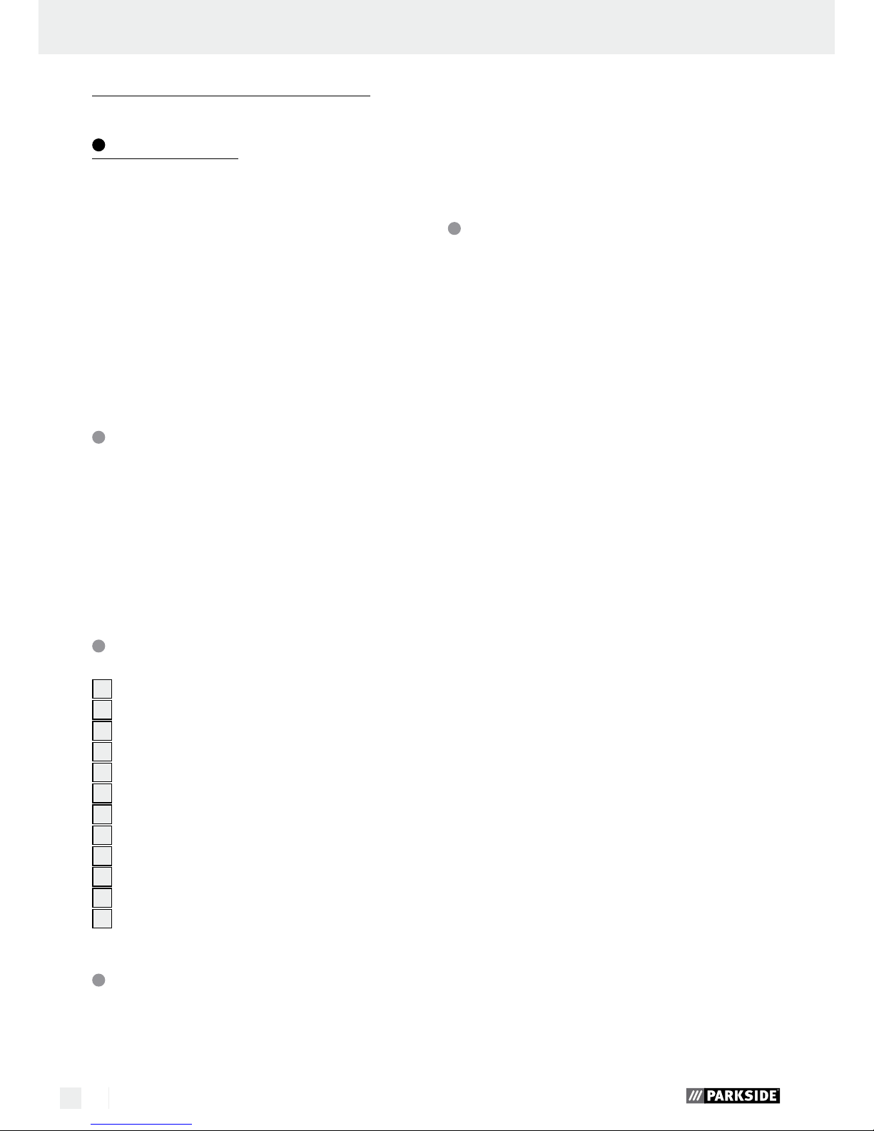
A
3 41 2
6789
12
11
10
5

B
C
D

5 GB
Table of contents
Introduction
Intended use ........................................................................................................................................ Page 6
Features and fittings ............................................................................................................................ Page 6
Included items .....................................................................................................................................Page 6
Technical data ..................................................................................................................................... Page 6
Safety of the fastener driving tool
Work safety ......................................................................................................................................... Page 7
Additional safety information for compressed air tackers ................................................................ Page 8
Original accessories / tools ................................................................................................................Page 8
Preparing the product for use
Connecting the compressed air source .............................................................................................Page 8
Loading the magazine ........................................................................................................................ Page 9
Operation .......................................................................................................................................Page 9
Removing jammed fasteners ...............................................................................................................Page 10
Maintenance and cleaning
Maintenance .......................................................................................................................................Page 10
Cleaning ..............................................................................................................................................Page 10
Service ...............................................................................................................................................Page 10
Warranty ......................................................................................................................................... Page 10
Disposal ............................................................................................................................................ Page 11
Translation of the original declaration of conformity /
Manufacturer ............................................................................................................................... Page 11
6 GB
Introduction
Pneumatic stapler PDT 40 C2
Introduction
We congratulate you on the purchase of your new
device. You have chosen a high quality product. The
operating instructions are part of the product. They
contain important information concerning safety,
use and disposal. Before using the product, familiarise yourself with all of the operating instructions
and safety instructions. Use the product only as described and for the specified applications. If you
pass the product on to anyone else, please ensure
that you also pass on all the documentation with it.
Intended use
The device is suitable for assembly and repair work.
Any other use or modification to the device shall be
considered as improper use and could give rise to
considerable dangers. We will not accept liability
for loss or damage arising from improper use. The
device is intended for private domestic use only.
Features and fittings
1
Exhaust air aperture (can be rotated)
2
Trigger
3
Handle
4
Threaded nipple 6.35 mm (¼”)
5
Magazine lever
6
Magazine
7
Fill level indicator
8
Knurled screw
9
Trigger lock
10
Mouth
11
Face plate
12
Face plate quick clamp lever
Included items
1 Pneumatic stapler PDT 40 C2
1 Carrying case
1 Special compressed air oil
1 Threaded nipple 6.35 mm (¼”) (pre-assembled)
1 Package nails, 1000 pcs.
1 Package staples, 1000 pcs.
1 Protective glasses
1 Operating instructions
Technical data
Dimensions: 240 x 57 x 235 mm
(L x H x W)
Weight
(without fasteners): 1.255 kg
Trigger type: Compressed air
Maximum permissible
pressure: 8 bar
Recommended pressure
range: 4 to 7 bar
Air consumption per
drive in process: approx. 0.09 litre per
driving-in process
Recommended lubricant:
Compressed air special oil
Loading capacity: 100 pcs.
Nail lengths: 15 mm, 20 mm
25 mm, 30 mm,
32 mm, 35 mm,
38 mm, 40 mm,
45 mm, 50 mm,
Staple lengths: 10–40 mm
Staple width: 5.7 mm
Recommended
Hose diameter: ∅ 9 mm
Compressed air quality: Cleaned, oil-misted
and condensate-free
Noise and vibration data:
Measured values for noise are determined in accordance with EN 12549:1999, EN ISO 4871.
The A-weighted sound pressure level of the device
is typically 114.3 dB(A). The sound power level of
the device is 125.6 dB(A). Uncertainty K = 2.5 dB.
These values are characteristic values referenced to
the device and do not reflect noise development at
the work location. Noise development at the work
location depends e.g. on the work environment, the
workpiece, the workpiece support and the number
of fastener driving processes.
7 GB
Introduction / Safety of the fastener driving tool
In correspondence with conditions at the work location, individual noise reduction measures may need
to be carried out, such as placing the workpiece on
a noise-suppressing surface, clamping or covering
to prevent workpiece vibration and adjusting to the
minimum pressure required by the work process. In
certain cases, wearing personal hearing protection
is require.
Wear hearing protection!
Vibration values in accordance with
ISO 8662-11:1999:
Vibration emission value a
h,W
= 15.0 m / s
2
Uncertainty K = 0.29 m / s
2
Mechanical impact (vibration)
The vibration value for the fastener driving device was
determined in accordance with ISO 8662-11:1999 —
Hand-held portable power tools – Measurement of
vibrations at the handle — Fastener driving tools
(see technical data). The value is referenced to the
device and does not represent the influence on the
hand-arm system when the device is used. Influence
on the hand-arm system when using the device depends on e.g. gripping force, pressing force, working direction, air pressure set, the workpiece and its
position.
Safety of the fastener
driving tool
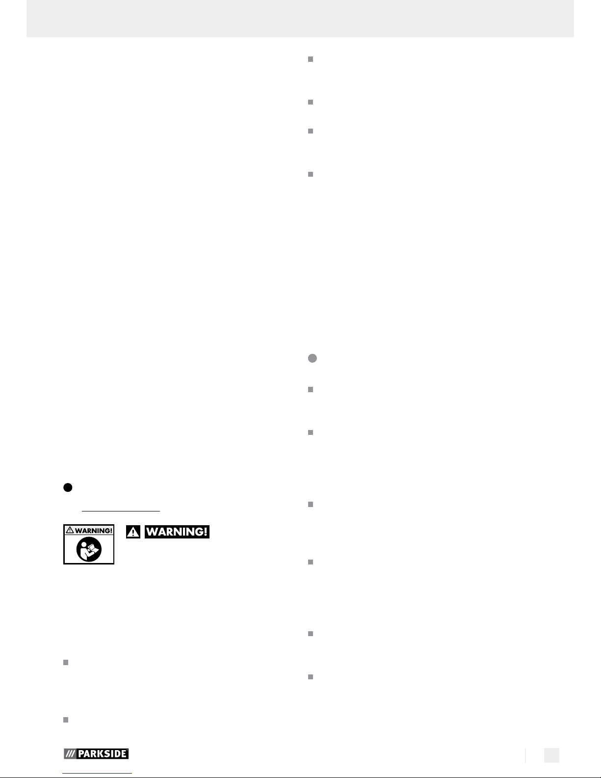
Please read
all the safety information and
instructions. Failure to comply with
the safety instructions and instructions can result in
severe injuries and / or damage to property.
PLEASE RETAIN ALL SAFETY INFORMATION
AND INSTRUCTIONS FOR FUTURE REFERENCE.
Each time before starting work, check
for flawless functioning of the safety
and triggering devices as well as the
firm fit of all bolts and nuts.
Do not conduct any improper manipu-
lation of the fastener driving tool.
Do not dismount or block any part of
the fastener driving tool, such a trigger lock.
Do not conduct any „emergency re-
pairs“ with unsuitable materials.
The fastener driving tool must be reg-
ularly and properly maintained as
specified by the manufacturer.
Prevent anything that would weaken
or damage the device, e.g. by:
– stamping or engraving,
– alterations not permitted by the
manufacturer,
– guiding on templates made of hard
material, e.g. steel,
– permitting to fall onto or slide across
the floor,
– using as a hammer,
– every type of external force.
Work safety
Never point a fastener driving tool that
is ready to use directly at yourself,
other persons or animals.
During work, hold the fastener driving
tool so that head and body can not be
injured by possible kickback due to a
fault in the power supply or from hard
places in the workpiece.
Never trigger the fastener driving tool
into empty space. Following this instruction
will prevent danger due to uncontrolled flying
fasteners and overloading the device.
Before transporting, disconnect the
fastener driving tool from the compressed air network, particularly when
using ladders or are moving with an
unaccustomed body posture.
At the workplace, only carry the fas-
tener driving tool by its grip and never
with the trigger actuated.
Pay attention to workplace conditions.
Fasteners may strike completely through thin
workpieces or slide off corners or edges to
cause a danger to persons.
8 GB
Safety of the fastener driving tool / Preparing the product for use
Use suitable personal protection equip-
ment, e.g. hearing and eye protection.
Wearing personal protective devices such as
dust mask, non-slip safety shoes, safety helmet
or hearing protectors, depending on the type
of fastener driving tool and its application, reduces the risk of injuries.
Additional safety information
for compressed air tackers
RISK OF INJURY! Never
exceed the maximum permissible operating
pressure of 8 bar. Use a pressure reducer to
adjust the operating pressure.
RISK OF INJURY! Never
use oxygen or other flammable gases as ener-
gy source.
Keep your working area clean and
well lit. Untidy or poorly lit working areas
can lead to accidents.
Keep children and other individuals
away from the fastener driving tool
during use. Distractions can cause you to
lose control of the device.
Remain alert at all times, watch what
you are doing and always proceed with
caution when working with a fastener
driving tool. Do not use any fastener
driving tool if you are tired or under the
influence of drugs, alcohol or medica
tion.
One moment of carelessness when using the fastener driving tool may result in serious injuries.
Avoid placing your body in an unnat-
ural position. Keep proper footing
and balance at all times. By doing this you
will be in a better position to control the fastener driving tool in unforeseen circumstances.
Before any repair and maintenance work or
transport, remove the device from the compressed air source.
RISK OF INJURY! Do not use the device on
scaffolds or ladders.
Never use hydrogen, oxygen, carbon dioxide
or other bottled gasses to power this tool as
doing so may result in an explosion and thus
may cause severe injuries.
RISK OF INJURY! Do not use the device if
the trigger lock
9
is damaged or has been
removed. Otherwise injuries may result.
When loosening the hose coupling, hold the
hose firmly in your hand to prevent injuries
caused by a rebounding hose.
Be absolutely certain to use a ¼” threaded
nipple and a quick-release coupling for the
compressed air connection.
Never place your hands near the mouth when
the device is ready to operate. Otherwise injuries may result.
Pay attention to damage. Check the de-
vice for damage before bringing it into use. If
the device exhibits defects, it must not be operated under any circumstances.
Do not use any pointed objects. Never
insert pointed and / or metal objects into the
inside of the device.
Original accessories / tools
Use only the accessories and attachment
s
detailed in the operating instructions.
The use of fasteners or other accessories other
than those recommended in the operating instructions could lead to you suffering an injury.
Preparing the product for use
NOTE: always wear the protective goggles supplied before putting the tool into operation. Remove
the protective film from the protective goggles before
using for the first time.
Connecting the compressed
air source
NOTE: The compressed air tacker must only be
operated with cleaned, oil-misted compressed air
and must not exceed the maximum operating pressure of 8 bar. The compressor must be fitted with a
pressure reducer in order to regulate the operating
pressure.

9 GB
Preparing the product for use / Operation
Connect the device to a suitable compressed
air source.
1. To do so, press the compressed air hose quickrelease coupling (not included in the scope of
delivery) on the ¼” threaded nipple
4
of the
compressed air tacker.
Locking is automatic.
2. Connect the other end of the compressed air
hose to the (filter) pressure reducer on the compressor.
Loading the magazine
1. Press the magazine lever 5 and pull the magazine cover back to its stop position.
2. Insert the corresponding fastener (nails, see
Fig. 01 or staples, see Fig. 02) into the magazine
6
. The tacks must be put on the rail of
the magazine
6
.
02
6
01
6
3. Slide the magazine cover forwards until it locks.
Operation
Load the magazine 6 of the compressed air
tacker as described in the chapter “Loading the
magazine“.
Use the pressure reducer to set the correct
operating pressure.
Ensure that the permissible operating pressure
of 8 bar at the device is never exceeded.
Operating pressure that is too high does not
provide any performance increase, but only increases compressed air consumption and ac-
celerates wear on the device.
Switch on the compressor.
Allow the compressor to run once long enough
until maximum tank pressure is reached and the
device is switched off.
Place the compressed air tacker on the workpiece
and press the trigger
2
.
NOTE: The compressed air tacker
is equipped with a trigger lock
9
.
The fastener will only
leave the device
when the mouth of the compressed air tacker is
pressed against the workpiece and the trigger 2
is actuated.
Check that the fastener has been driven in cor-
responding to the work requirements.
– If the fastener is protruding, increase the air
pressure in 0.5 bar increments.
– If the fastener is too deep, decrease the air
pressure in 0.5 bar increments.
As an alternative, you can accelerate the work
by keeping the trigger
2
depressed.
Set the compressed air tacker against the work-
piece.
Press the device against the workpiece until the
mouth
10
touches it. The fastener will leave the
device.
As long as the trigger 2 is kept depressed, each
time the mouth
10
touches the workpiece one
fastener will leave the device.
Another alternative is to keep the mouth
10
pressed against the workpiece.
Each time the trigger 2 is actuated, a fastener
will leave the device.
NOTE: Fine adjustment with the knurled screw
8
is possible.
Turn the knurled screw 8 downwards in order
to drive the fastener more deeply into the workpiece.
Turn the knurled screw 8 upwards in order to
drive the fastener less deeply into the workpiece.

10 GB
… / Disposal / Translation of the original declaration of conformity / Manufacturer
Operation / Maintenance and cleaning / Service / Warranty
Turn the exhaust air aperture 1 to guide the
exhaust airflow in the desired direction.
After finishing work, disconnect the device from
the compressor.
Removing jammed fasteners
If a staple or nail gets jammed in the magazine
slot, immediately disconnect the compressed
air supply.
Open the magazine 6 as described in the
chapter “Loading the magazine“.
Open the face plate 11 by pulling the face
plate quick clamping lever
12
in the direction
of the trigger lock
9
.
Remove the jammed fastener.
Close the face plate 11 by pulling the face
plate quick clamping lever
12
in the direction
of the exhaust air aperture
1
.
Close the magazine 6 of the compressed air
tacker as described in the chapter “Loading the
magazine“.
Maintenance and cleaning
RISK OF INJURY! Be absolutely certain to
disconnect the device from the compressed air
source before cleaning or maintaining it.
Maintenance
Lubrication with oil mister
NOTE: As a treatment stage after the pressure re-
ducer, an oil mister provides continuous and opti
mum
lubrication of the compressed air tacker. An oil mister gives off fine drops of oil into the airflow and so
guarantees regular lubrication.
Install the oil mister after the (filter) pressure re-
ducer. To do so, insert the nipple of the oil mister
into the quick-release coupling of the (filter)
pressure reducer.
Then connect the compressed air device to the
quick-release coupling provided for it.
Manual lubrication
NOTE: If you do not have an oil mister, lubricate the
device each time after driving about 5000 fasteners.
Apply 1–2 drops of special compressed air oil
into the threaded nipple
4
of the compressed
air tacker.
Then press the trigger 2 several times.
ATTENTION: Be certain not to use too much
oil; otherwise oil could leave the mouth with the
fastener and potentially damage the workpiece.
Cleaning
Do not use any sharp objects to clean the device.
Do not allow any liquids to enter the device.
Otherwise the device could be damaged.
Clean the device regularly, preferably always
immediately after finishing work.
Use a dry cloth to clean the housing. Under no
circumstances should you use petrol, solvent or
cleaners which attack plastic.
After each use, pack the compressed air tacker
in the carrying case it was delivered with to
protect it from dirt.
Service
Have your fastener
driving tool repaired only by qualified
specialist personnel using original manufacturer parts only. This will ensure that
your fastener driving tool remains safe to use.
Note: Spare parts not listed (e.g. carbon brushes,
switches) can be ordered through our call centre.
Warranty
The warranty for this appliance is for 3
years from the date of purchase. The appliance has been manufactured with care
and meticulously examined before delivery. Please retain your receipt as proof
of purchase. In the event of a warranty
claim, please make contact by telephone
11 GB
… / Disposal / Translation of the original declaration of conformity / Manufacturer
with our Service Department. Only in this
way can a post-free despatch for your
goods be assured.
The warranty covers only claims for material and
maufacturing defects, but not for transport damage,
for wearing parts or for damage to fragile components, e.g. buttons or batteries. This product is for private use only and is not intended for commercial use.
The warranty is void in the case of abusive and improper handling, use of force and internal tampering
not carried out by our authorized service branch. Your
statutory rights are not restricted in any way by this
warranty.
The warranty period will not be extended by repairs
made unter warranty. This applies also to replaced
and repaired parts. Any damage and defects extant
on purchase must be reported immediately after
unpacking the appliance, at the latest, two days after
the purchase date. Repairs made after the expiration
of the warranty period are subject to payment.
GB
Service Great Britain
Tel.: 0871 5000 720
(0,10 GBP/Min.)
e-mail: kompernass@lidl.co.uk
IAN 96899
Disposal
The packaging is made entirely of recyclable materials which you can dispose
of at your local recycling facilities.
Do not dispose of the product with
household rubbish!
Contact your local refuse disposal authority for
more details of how to dispose of your worn out
electrical devices.
Translation of the original
declaration of conformity /
Manufacturer
We, KOMPERNASS HANDELS GMBH, the person
responsible for documents: Mr Semi Uguzlu, BURGSTRASSE 21, 44867 BOCHUM, GERMANY, hereby
declare that this product complies with the following
standards, normative documents and EU directives:
Machinery Directive
(2006 / 42 / EC)
Applicable harmonised standards:
EN 792-13:2000+A1
Type / Description of product:
Pneumatic stapler PDT 40 C2
Date of manufacture (DOM): 03–2014
Serial number: IAN 96899
Bochum, 31.03.2014
Semi Uguzlu
- Quality Manager -
We reserve the right to make technical modifications
in the course of product development.

12

13 HU
Tartalomjegyzék
Bevezetés
Rendeltetésszerű használat ...............................................................................................................Oldal 14
Felszereltség .......................................................................................................................................Oldal 14
A csomagolás tartalma ......................................................................................................................Oldal 14
Műszaki adatok .................................................................................................................................Oldal 14
A kötőelem-belövő készülék biztonsága
Munkabiztonság ................................................................................................................................Oldal 15
Kiegészítő biztonsági utasítások sűrített levegős tűzőgépekhez .....................................................Oldal 16
Eredeti tartozékok / kiegészítő készülékek .......................................................................................Oldal 16
Üzembe helyezés
A sűrített levegő csatlakoztatása ......................................................................................................Oldal 17
A tár feltöltése ....................................................................................................................................Oldal 17
Kezelés .............................................................................................................................................Oldal 17
A beszorult kapcsok eltávolítása ......................................................................................................Oldal 18
Karbantartás és tisztítás
Karbantartás .......................................................................................................................................Oldal 18
Tisztítás ................................................................................................................................................Oldal 18
Szerviz ..............................................................................................................................................Oldal 19
Garancia .........................................................................................................................................Oldal 19
Mentesítés .....................................................................................................................................Oldal 19
Az eredeti EU-Megfelelőségi Nyilatkozat fordítása / Gyártó ...........Oldal 20

14 HU
Bevezetés
Pneumatikus tűzőgép PDT 40 C2
Q
Bevezetés
Gratulálunk új készülékének vásárlása alkalmából.
Ezzel a döntésével vállalatunk értékes terméke mellett döntött. A
használati utasítás ezen termék része.
A
biztonságra, a használatára és a megsemmisítésre
vonatkozó fontos tudnivalókat tartalmazza. A termék
használata előtt ismerje meg az összes használati
és biztonsági tudnivalót. A terméket csak a leírtak
szerint és a megadott felhasználási területeken alkalmazza. A termék harmadik személy számára
való továbbadása esetén kézbesítse vele annak a
teljes dokumentációját is.
Rendeltetésszerű használat
A készülék szerelési és javítási munkákra alkalmas.
Minden másfajta alkalmazás, vagy a gép megváltoztatása nem rendeltetésszerűnek minősül és
jelentős balesetveszélyt rejt magában. A
rendeltetéstől eltérő alkalmazásból származó károkért nem vállalunk felelősséget. A készüléket csak
magánhasználatra tervezték.
Felszereltség
1
Távozólevegő-terelő (forgatható)
2
Kioldó
3
Fogantyú
4
Menetes csatlakozó, 6,35 mm (¼")
5
Táremelő
6
Tár
7
Töltöttségjelző
8
Recézett fejű csavar
9
Kioldó biztosíték
10
Torkolat
11
Homloklemez
12
Homloklemez gyorsszorító emelője
A csomagolás tartalma
1 pneumatikus tűzőgép PDT 40 C2
1 hordozókoffer
1 speciális sűrítettlevegő-olaj
1 menetes csatlakozó, 6,35 mm (¼") (előszerelt)
1 csomag szög, 1000 darab
1 csomag kapocs, 1000 darab
1 védőszemüveg
1 használati útmutató
Műszaki adatok
Méret: 240 x 57 x 235 mm
(Szé x Ma x Mé)
Súly (kötőelemek nélkül): 1,255 kg
Kioldás: sűrített levegős
Megengedett max. nyomás: 8 bar
Ajánlott nyomástartomány: 4–7 bar
Levegőfogyasztás
belövésenként: kb. 0,09 l/belövés
Ajánlott kenőanyag: speciális sűrítettlevegő-
olaj
Töltési kapacitás: 100 darab
Szögek hossza: 15 mm, 20 mm, 25 mm,
30 mm, 32 mm, 35 mm,
38 mm, 40 mm, 45 mm,
50 mm
Kapcsok hossza: 10–40 mm
Kapcsok szélessége: 5,7 mm
Ajánlott
tömlőátmérő: ∅ 9 mm
Sűrített levegő minősége: tisztított, olajozott és
kondenzátumtól mentes
Zaj és vibráció:
A mért értékek megállapítása az EN 12549:1999,
EN ISO 4871 szerint történt. A készülék A-hangnyomásszintje jellemzően 114,3 dB(A). A zajszint
125,6 dB(A). Bizonytalanság K = 2,5 dB.
Az értékek a készülékre vonatkoztatott jellemzőket
tükrözik, nem az alkalmazási helyen fellépő zajt. Az
alkalmazási helyen fellépő zaj függ a munkakörnyezettől, a munkadarabtól, a munkadarab-alátéttől, a
belövések számától stb.

15 HU
Bevezetés / A kötőelem-belövő készülék biztonsága
A munkahelyi viszonyoknak és a munkadarab típusának megfelelően adott esetben zajszigetelést
célzó intézkedéseket kell hozni; a munkadarabokat
pl. zajszigetelő felületre kell helyezni, befogással
vagy lefedéssel meg kell akadályozni a munkadarabok vibrációját, vagy pl. a munkafolyamathoz
szükséges legkisebb nyomást kell beállítani. Rendkívüli esetekben hallásvédő eszközt kell viselni.
Viseljen hallásvédőt!
Az ISO 8662-11:1999 szerinti rezgési
összértékek:
Rezgéskibocsátási érték a
h,W
= 15,0 m / s
2
Bizonytalanság K = 0,29 m / s
2
Mechanikai ütések (vibráció)
A kötőelem-belövő készülék vibrációs értékének
megállapítása az ISO 8662-11:1999 szerint történt — Hordozható motoros kéziszerszámok — A mechanikai rezgések mérése a fogantyún — Kötőelembelövő készülékek (lásd a Műszaki adatlapot). Az
érték a készülékre vonatkoztatott jellemzőt tükrözi,
nem a készülék alkalmazása közbeni, kéz-kar
rendszerre gyakorolt hatást. A készülék alkalmazása közbeni, kéz-kar rendszerre gyakorolt hatás függ
a tartóerőtől, a leszorítóerőtől, a munkairánytól, a
beállított légnyomástól, a munkadarabtól, a munkadarab-alátéttől stb.
A kötőelem-belövő készülék
biztonsága
Olvassa
el az összes biztonsági tudnivalót és utasítást. A biztonsági
tudnivalók és utasítások betartása alkalmával elkövetett mulasztások súlyos sérüléseket és / vagy tárgyi
károsodásokat okozhatnak.
ŐRIZZEN MEG MINDEN BIZTONSÁGI
TUDNIVALÓT ÉS UTASÍTÁST A JÖVŐBENI
FELHASZNÁLÁS CÉLJÁBÓL.
Minden munka előtt ellenőrizni kell a
biztonsági és kioldó szerkezetek kifo-
gástalan működését, valamint a csavarok és anyák megfelelő rögzítését.
A kötőelem-belövő készüléken tilos
rendellenes változtatásokat végrehajtani.
Tilos leszerelni vagy blokkolni a
kötőelem-belövő készülék alkatrészeit,
pl. a kioldó biztosítékot.
Ne hajtson végre „rendkívüli javítá-
sokat” arra alkalmatlan eszközökkel.
A kötőelem-belövő készülék karbant-
artását rendszeresen és szakszerűen,
a gyártói utasítások szerint kell végezni.
Kerülje a készülék bármilyen jellegű
gyengülését és károsodását, amelyet pl.
– ütés vagy gravírozás,
– a gyártó által nem engedélyezett
változtatás,
– a kemény anyagból, pl. acélból kés-
zült sablonokon történő vezetés,
– a földre ejtés vagy a padlón való
végigtolás,
– a kalapácsként való alkalmazás,
– vagy bármilyen erőszakos behatás
okozhat.
Munkabiztonság
Az üzemkész kötőelem-belövő készü-
léket tilos magára vagy másokra irányítani.
A kötőelem-belövő készüléket munka
közben úgy kell tartani, hogy az
energiaellátási zavarok vagy a munkadarab kemény részei által okozott
lehetséges visszacsapódás miatt a fej
és a többi testrész ne sérülhessen.
A kötőelem-belövő készüléket tilos a
levegőbe irányítani. Ezáltal elkerülhetők
a kirepülő kötőelemek és a készülék túlterhelése által okozott veszélyek.
Szállításhoz válassza le a kötőelem-
belövő készüléket a sűrített levegős
hálózatról, különösen akkor, ha létrát
használ vagy szokatlan testhelyzetben
végez mozgást.
16 HU
A kötőelem-belövő készülék biztonsága
A kötőelem-belövő készüléket a
munkahelyen csak a fogantyúnál fogva, a kioldó működtetése nélkül szabad hordozni.
Ügyeljen a munkahelyi körülményekre.
A kötőelemek adott esetben átlyukaszthatják a
vékony munkadarabokat vagy a sarkoknál és
éleknél végzett munka közben lecsúszhatnak a
munkadarabról, veszélyeztetve ezáltal másokat.
A saját védelme érdekében használjon
megfelelő védőfelszerelést, pl. hallásés szemvédő eszközöket. A személyi
védőfelszerelések (pl. porvédő maszk, csúszásgátló cipő, védősisak vagy hallásvédő) használata, a kötőelem-belövő készülék alkalmazása
és típusa szerint, csökkenti a sérülések veszélyét.
Kiegészítő biztonsági
utasítások sűrített levegős
tűzőgépekhez
SÉRÜLÉSVESZÉLY!
Ne lépje túl a megengedett maximális munka-
nyomást 8 bar. A munkanyomás beállításához
használjon nyomáscsökkentőt.
SÉRÜLÉSVESZÉLY!
Energiaforrásként soha ne használjon oxigént
vagy más gyúlékony gázokat.
Tartsa tisztán és jól megvilágítva a
munkaterületet. A rendetlenség és a kivi-
lágítatlan munkakörnyezet balesetekhez vezethet.
Tartsa távol a gyerekeket és más sze-
mélyeket a kötőelem-belövő készülék
használata közben. Ha figyelmét máshova
irányítja, elveszítheti a készülék feletti uralmat.
Legyen mindig figyelmes, ügyeljen arra,
amit tesz, és kellő óvatossággal kezdje
meg a munkavégzést a kötőelem-belövő
készülékkel. Ne használja a kötőelembelövő készüléket, ha fáradt, vagy ha
drog, alkohol vagy gyógyszer hatása
alatt áll. A kötőelem-belövő készülék hasz-
nálata közben már egy pillanatnyi figyelmetlenség is komoly sérülésekhez vezethet.
Kerülje az abnormális testtartást.
Gondoskodjon róla, hogy biztosan
álljon és mindig tartsa meg az
egyensúlyát. Ezáltal váratlan helyzetekben
jobban tudja uralni a kötőelem-belövő készüléket.
A javítási és karbantartási munkák, valamint
szállítások előtt válassza le a készüléket a sürített levegős forrásról.
SÉRÜLÉSVESZÉLY! Ne használja a készü-
léket állványzatokon vagy létrákon.
Ne használjon energiaforrásként hidrogént,
oxigént, széndioxidot vagy más gázt tartalmazó
palackot, mert az robbanást és ezáltal súlyos
sérüléseket okozhat.
SÉRÜLÉSVESZÉLY! Ne helyezze üzembe a
készüléket, ha a kioldó biztosíték
9
hibás vagy
el van távolítva. Ellenkező esetben sérülést
szenvedhet.
A tömlőcsatlakozó kioldása közben az esetle-
gesen visszacsapódó tömlő általi sérülések elkerülése érdekében fogja a tömlőt szorosan a
kezében.
A sűrített levegő csatlakoztatásához mindenképp
¼"-os menetes csatlakozót és gyorscsatlakozót
kell használni.
Kezeivel soha ne közelítse meg a torkolatot, ha
a készülék üzemkész állapotban van. Ellenkező
esetben sérülést szenvedhet.
Ügyeljen a készülék károsodásaira.
Üzembe helyezés előtt ellenőrizze a készülék
esetleges károsodásait. Ha a készülék hibás,
semmi esetre sem szabad üzembe helyezni.
Ne használjon hegyes tárgyakat. Ne
dugjon hegyes és/vagy fém tárgyakat a készülék belsejébe.
Eredeti tartozékok / kiegészítő
készülékek
Csak a kezelési útmutatóban megadott
tartozékokat és kiegészítő készülékeket szabad használni. A használati útmu-
tatóban megadottaktól eltérő kötőelemek vagy
más tartozékok használata sérülésveszélyt
eredményezhet.
 Loading...