

Page 1
V iX250IM
V iX500IM
Stepper Drives
User Guide
Part No: 1600.324.01b February, 2004 (For software revision 2.0 onwards)
Page 2

Page 3
IMPORTANT INFORMATION FOR USERS
Installation and Operation of Motion Control Equipment
It is important that motion control equipment is installed and operated in such a way that all applicable safety
requirements are met. It is your responsibility as an installer to ensure that you identify the relevant safety
standards and comply with them; failure to do so may result in damage to equipment and personal injury. In
particular, you should study the contents of this user guide carefully before installing or operating the
equipment.
The installation, set-up, test and maintenance procedures given in this User Guide should only be carried
out by competent personnel trained in the installation of electronic equipment. Such personnel should be
aware of the potential electrical and mechanical hazards associated with mains-powered motion control
equipment - please see the safety warning below. The individual or group having overall responsibility for
this equipment must ensure that operators are adequately trained.
Under no circumstances will the suppliers of the equipment be liable for any incidental, consequential or
special damages of any kind whatsoever, including but not limited to lost profits arising from or in any way
connected with the use of the equipment or this user guide.
SAFETY WARNING
High-performance motion control equipment is capable of producing rapid movement and very high forces.
Unexpected motion may occur especially during the development of controller programs. KEEP WELL
CLEAR of any machinery driven by stepper or servo motors. Never touch any part of the equipment while it
is in operation.
This product is sold as a motion control component to be installed in a complete system using good
engineering practice. Care must be taken to ensure that the product is installed and used in a safe manner
according to local safety laws and regulations. In particular, the product must be enclosed such that no part
is accessible while power may be applied.
This and other information from Parker-Hannifin Corporation, its subsidiaries and authorised distributors
provides product or system options for further investigation by users having technical expertise. Before you
select or use any product or system, it is important that you analyse all aspects of your application and
review the information concerning the product in the current product catalogue. The user, through its own
analysis and testing, is solely responsible for making the final selection of the system and components and
assuring that all performance, safety and warning requirements of the application are met.
If the equipment is used in any manner that does not conform to the instructions given in this user guide,
then the protection provided by the equipment may be impaired.
The information in this user guide, including any apparatus, methods, techniques, and concepts described
herein, are the proprietary property of Parker Electromechanical Division or its licensors, and may not be
copied, disclosed, or used for any purpose not expressly authorised by the owner thereof.
Since Parker Electromechanical constantly strives to improve all of its products, we reserve the right to
modify equipment and user guides without prior notice. No part of this user guide may be reproduced in any
form without the prior consent of Parker Electromechanical Division.
© Electromechanical Division of Parker Hannifin plc, 2003
– All Rights Reserved –
Page 4

Product Type: ViX250IM, ViX500IM
The above product is in compliance with the requirements of directives
• 73/23/EEC Low Voltage Directive
• 93/68/EEC CE Marking Directive
• 89/336/EEC Electromagnetic Compatibility Directive
Provided the installation requirements described in this user guide are met, and there are no special requirements of
the installation and operating environment so that the application may be considered typical, the ViX servo drive series
installation will conform to the protection requirements of Council Directive 89/336/EEC as amended by Directive
92/31/EEC on the approximation of the laws of the Member States relating to Electromagnetic Compatibility when
operated and maintained as intended.
In assessing the overall compliance of an installation consideration must also be given to the effects of mains
harmonics and flicker when interfacing the total supply system to the public low voltage supply system.
In accordance with IEC 61800-3:1997 (Adjustable speed electrical power drive systems) this product is of the
restricted sales distribution class which meets the needs of an industrial environment when installed as directed.
However, further measures may need to be taken for use of the product in a domestic environment.
Compliance is demonstrated by the application of the following standards:
BS EN 61800-3 Adjustable speed electrical power drive systems
(1997) including Part 3. EMC product standard including specific test methods
Amendment A11
BS EN 61000-6-2 Electromagnetic compatibility – Part 6-2: Generic standards
(2001) Immunity for industrial environments
BS EN 61000-6-4 Electromagnetic compatibility – Part 6-4: Generic standards –
(2001) Emission standard for industrial environments
BS EN 61010-1 Safety requirements for electrical equipment for measurement,
(1993) including control, and laboratory use. Part 1. General requirements
Amendment A2
WARNING – Risk of damage and/or personal injury
The ViX drives described in this user guide contain no user-serviceable parts.
Attempting to open the case of any unit, or to replace any internal component, may
result in damage to the unit and/or personal injury. This may also void the
warranty.
Page 5
Contact Addresses
For engineering For engineering
assistance in Europe: assistance in Germany
Parker Hannifin plc Parker Hannifin GmbH
Electromechanical Electromechanical
Automation
21 Balena Close P. O. Box: 77607-1720
Poole, Dorset Robert-Bosch-Str. 22
England, BH17 7DX D-77656 Offenburg, Germany
Tel: +44 (0)1202-699000 Tel: +49 (0)781 509-0
Fax: +44 (0)1202-695750 Fax: +49 (0)781 509-176
e-mail: sales.digiplan@parker.com e-mail: sales.hauser@parker.com
e-mail: support.digiplan@parker.com e-mail: techhelp_emd_OG@parker.com
Website: www.parker-eme.com Website: www.parker-eme.com
For engineering For engineering
assistance in Italy assistance in the U.S.:
Parker Hannifin SpA Parker Hannifin Corporation
Electromechanical Automation
20092 Cinisello Balsamo 5500 Business Park Drive, Suite D
Milan, Rohnert Park
Italy Via Gounod, 1 CA 94928
Tel: +39 02 6601 2478 Tel: (800) 358-9070
Fax: +39 02 6601 2808 Fax: (707) 584-3793
e-mail: sales.sbc@parker.com e-mail: emn_support@parker.com
Website: www.parker-eme.com Website: www.parkermotion.com
Automation
Electromechanical Automation
USA
FaxBack System: (800) 936-6939
Symbols used, have the following meanings:
Caution Refer to the
accompanying documentation
Protective conductor terminal
Page 6

CONTENTS i
Contents
1. Introduction.............................................................................................................1
2. Mechanical Installation...........................................................................................5
3. Electrical Installation...............................................................................................9
4. Control of ViX Drives..............................................................................................45
5. EASI-V Software ....................................................................................................95
6. Command Reference.............................................................................................115
7. ViX Maintenance and Troubleshooting ..................................................................185
8. Hardware Reference ..............................................................................................195
Appendix A/B..............................................................................................................199
Index............................................................................................................................203
The ViX250IM/500IM Microstepper Indexer Drive is UL-Recognised under file E194158.
This means it may be incorporated into end-user products that may be eligible for UL
Listing, Classification or Certification.
User Guide Issue Change Summary
This user guide, version 1600.324.01, is the first version of the ViX250IM/ViX500IM
Microstepper Indexer Drive.
When a user guide is updated, the new or changed text is differentiated with a change
bar in the outside margin (this paragraph is an example). If an entire section is changed,
the change bar is located on the outside margin of the section title. For the latest (most
up-to-date) changes required by this issue of user guide see the Latest Changes Sheet
over the page.
Page 7

ii VIX IM MICROSTEPPER INDEXER DRIVE USER GUIDE
Latest Changes Sheet
This page lists important changes occurring immediately before publication or between
issue updates:
Page 8
1. INTRODUCTION 1
1. Introduction
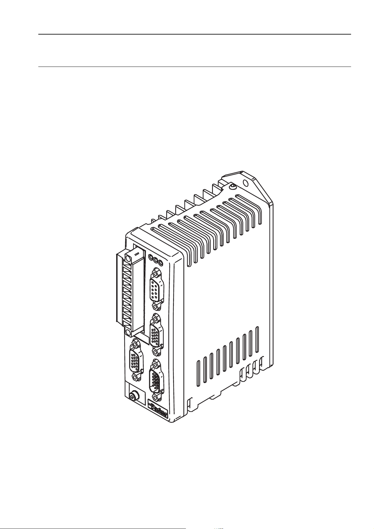
Product Description
Available in two current ratings, these microstepper indexer drives employ an optimised
digital field oriented current loop to provide low speed smoothness coupled with high speed
torque. Advanced digital techniques result in reduced settling time and reduced mid speed
instability when compared with similar competitive drive types.
The common use of EASI-V programming language and similar supply requirements make
this drive ideal for mixed technology applications when used with the ViX digital servo.
Figure 1-1. ViX250/ViX500 Microstepper Indexer Drive
Page 9

2 VIX IM MICROSTEPPER INDEXER DRIVE USER GUIDE
Product Variants
Digital microstepper indexer drives are available in two current ratings with two interface
options. Table 1-1 lists the possible combinations:
Product Code Description
ViX500IM 5.6A RMS (8A peak) microstepper indexer drive with an
RS232 control interface
ViX250IM 2.8A RMS (4A peak) microstepper indexer drive with an
RS232 control interface
ViX500CM 5.6A RMS (8A peak) microstepper indexer drive with
Canbus/RS485 interface
ViX250CM 2.8A RMS (4A peak) microstepper indexer drive with
Canbus/RS485 interface
Table 1-1. ViX250/ViX500 Microstepper Indexer Drive Options
Note: RS485 serial communication is only included in the CANopen version of the drive.
Product Features
Protection Circuits
Motor short circuits, phase to phase,
phase to ground
Over-voltage trip
Under-voltage trip
Drive/motor Over-temperature
24V reverse supply protection
Function Indicators
Drive Status/Feedback Fault (HV/FB)
Drive Fault (DF)
Comms. Status (CS)
Outputs and Inputs
3 digital outputs
5 digital inputs
1 analogue input
Page 10

Fit Kits
A fit kit is available for ViXIM drives:
VIX-KIT
Part Number Quantity Description
1650.937.01 1 Information
5004.023 1 Plastic bag
5006.211 1 Product label
0405.811 1 10-way Flange
0405.961 1 9-way D-type
0405.962 2 15-way HD
0405.963 1 15-way HD
0409.530 4 9-way D-type
0313.020 1 H8FE1115NC
4005.218 1 3:1 heatshrink
4216.101 1 Closed P-clip
4216.102 1 Closed P-clip
4216.103 1 Closed P-clip
1. INTRODUCTION 3
sheet
plug strip
plug
D-type plug
D-type socket
cover
ferrite sleeve
19mm diam.
9mm ID
10.7mm ID
12.3mm ID
Page 11

4 VIX IM MICROSTEPPER INDEXER DRIVE USER GUIDE
Further Information
This user guide contains all the necessary information for the effective use of this drive.
However, to gain a more in-depth understanding of drive applications and motion control,
consider attending one of our world-wide Customer Specific Training Workshops.
Examples of previous courses that have proved to be of benefit include:
Use and programming of the DIN rail H & L series drives
PDFX training
Using the 6K controller
EASI Tools programming
Mechanical product training for ET/ER, XR and HPLA
Page 12

2. MECHANICAL INSTALLATION 5
2. Mechanical Installation
Installation Requirements
Environment
ViX drives operate in a temperature range of 0° to 40°C with natural convection, or 50°C
Max with forced-air cooling (see Hardware Reference), at normal levels of humidity (5-95%
non-condensing). The drives can tolerate atmospheric pollution degree 2, which means only
dry, non-conductive pollution is acceptable.
Drive Cooling
Cooling of all drive types is by natural convection up to 40°C. To assist cooling, drives
should be installed vertically in an area where there is at least a 50mm (minimum) air gap
above and below the package and a 10mm (minimum) gap either side. Avoid mounting
heat-producing equipment directly below a drive.
Installers must ensure that the air temperature entering the drive or rising up to the drive is
within the ambient temperature restrictions. Under normal use the air temperature leaving
the drive and heatsink may be 25°C above ambient.
In the final installation, check that the ambient temperature specification of 40°C Max
(without forced air cooling) is not exceeded directly below the top-most drives and that any
circulating air flow is not being blocked from reaching the drives. For cabinet cooling
calculations, allow 20W per drive. For DIN rail mounting, see the thermal limitations
statement in Drive Mounting Options.
Page 13
6 VIX IM MICROSTEPPER INDEXER DRIVE USER GUIDE
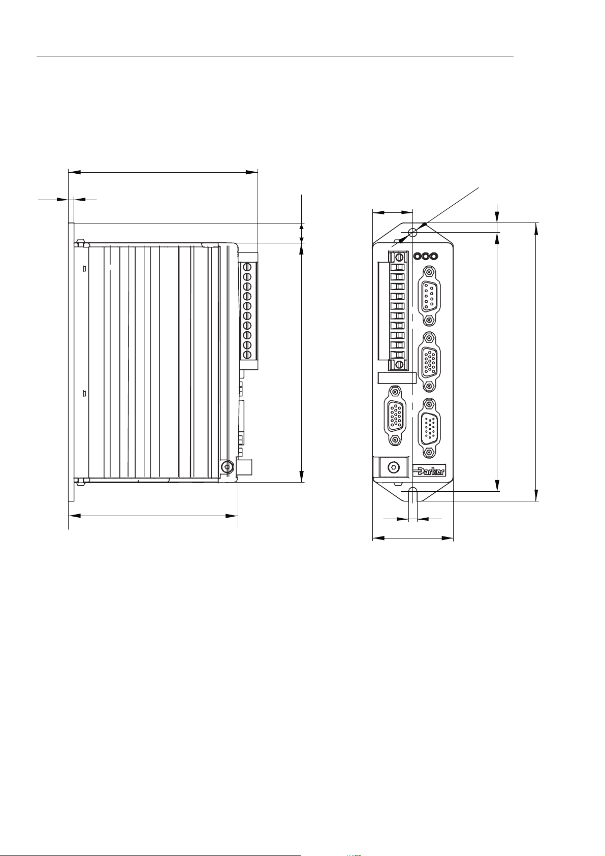
Drive Dimensions
ViX250 and ViX500 drives share the same dimensions, shown in Figure 2-1.
98.5 (with connector)
3
10.1
124.7
21
X1
X2
HVSTFB
X3
X4
X5
5
135
145
4,5
88,1
4,5
42
Figure 2-1. ViX250 & ViX500 Dimensions
Page 14
2. MECHANICAL INSTALLATION 7
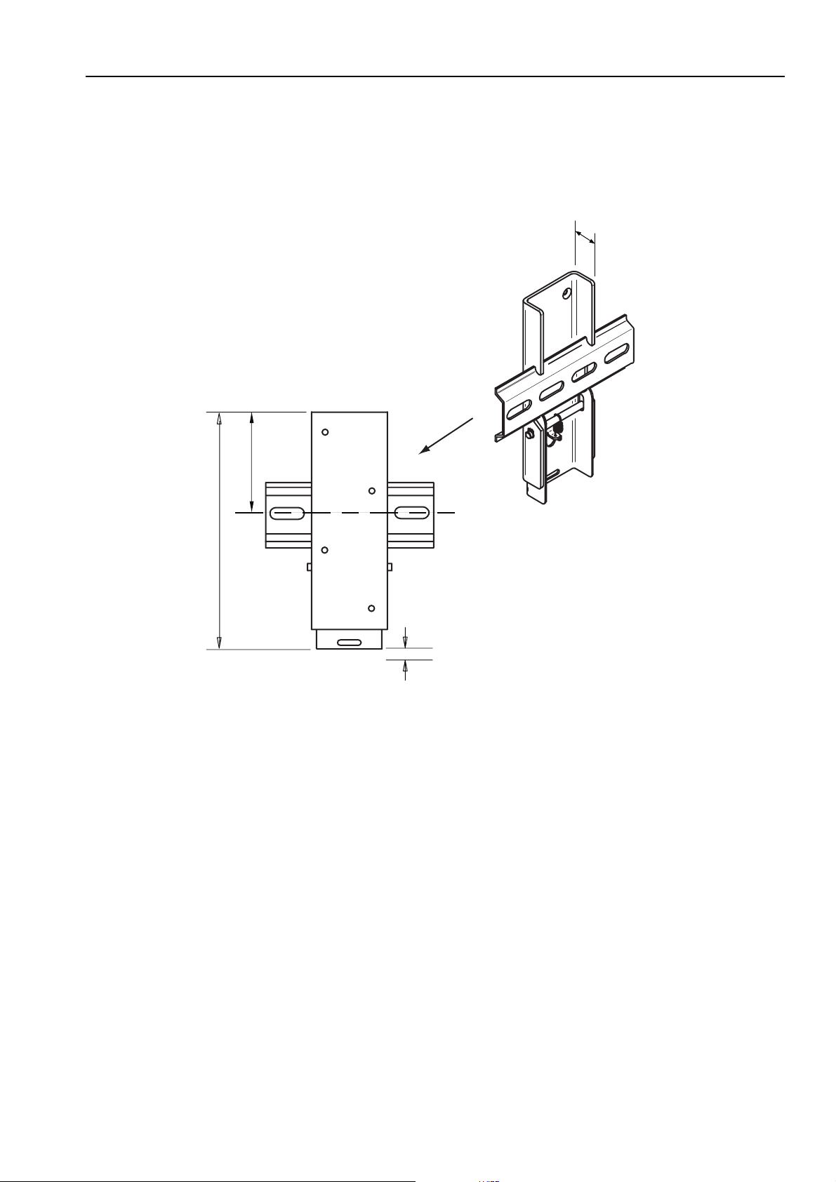
Drive Mounting Options
If you require a DIN-Rail mounting ViX drive use the optional DIN-Rail clip adapter bracket
shown in Figure 2-2.
16mm
57.2mm
Viewed from the back
131.2mm
of the DIN rail
Allow 10mm
for release
Figure 2-2. DIN-Rail Adapter Bracket
Remove the panel mounting plate from the back of the drive and attach the bracket to the
back of the drive using the screws provided. The drive and bracket can now be fixed to a
DIN rail by hooking the top of the bracket over the top of the DIN rail and gently pushing the
drive forward to engage the lower section of the bracket. Remove the bracket by inserting a
flat bladed screwdriver into the release slot to pull down the bottom of the bracket, releasing
it from the DIN rail.
Page 15

8 VIX IM MICROSTEPPER INDEXER DRIVE USER GUIDE
Motor Mounting Mechanical Considerations
Keep motors securely fixed in position at all times. Do not test a motor/drive combination
without first securing the motor – see the Safety Warning at the front of this user guide.
CAUTION – risk of equipment damage
Do not back drive the motor, that is use the motor in an application that causes
mechanical rotation of the motor shaft in a manner uncontrolled by the drive.
Back driving the motor at high speed may damage the drive.
Page 16

3. ELECTRICAL INSTALLATION 9
3. Electrical Installation
Installation Safety Requirements
ViX stepper drives meet the requirements of both the European LVD & EMC directives when
installed according to the instructions given within this section. It is recommended the drive
be installed in an enclosure to protect it from atmospheric contaminants and to prevent
operator access while it has power applied. Metal equipment cabinets are ideally suited for
housing the equipment since they can provide operator protection, EMC screening, and can
be fitted with interlocks arranged to remove all hazardous motor and drive power when the
cabinet door is opened. Do not arrange interlocks to open circuit the motor phase
connections while the system is still powered, as this could cause damage to the drive.
Precautions
During installation, take the normal precautions against damage caused by electrostatic
discharges. Wear earth wrist straps. A switch or circuit breaker must be included in the
installation, which must be clearly marked as the disconnecting device and should be within
easy reach of the machine operator.
Cabinet Installation
To produce an EMC and LVD compliant installation we recommend that drives are mounted
within a steel equipment cabinet. This form of enclosure is not essential to achieving EMC
compliance, but does offer the benefits of operator protection and reduces the contamination
of the equipment from industrial processes.
A steel equipment cabinet will screen radiated emissions provided all panels are bonded to a
central earth point. Separate earth circuits are commonly used within equipment cabinets to
minimise the interaction between independent circuits. A circuit switching large currents and
sharing a common earth return with another low level signal circuit could conduct electrical
noise into the low level circuit, thereby possibly interfering with its operation. For this reason
so called ‘dirty earth’ and ‘clean earth’ circuits may be formed within the same cabinet, but all
such circuits will eventually need to be returned to the cabinet’s main star earth point.
Mount the individual drives and EMC filter on a metal earth plane. The earth plane will have
its own individual star point earth which should be hard wired (using an insulated copper
conductor) back to the cabinet’s ‘clean earth’ connection point.
LVD - Low voltage directive
EMC – Electro Magnetic Compatibility directive
Page 17
10 VIX IM MICROSTEPPER INDEXER DRIVE USER GUIDE
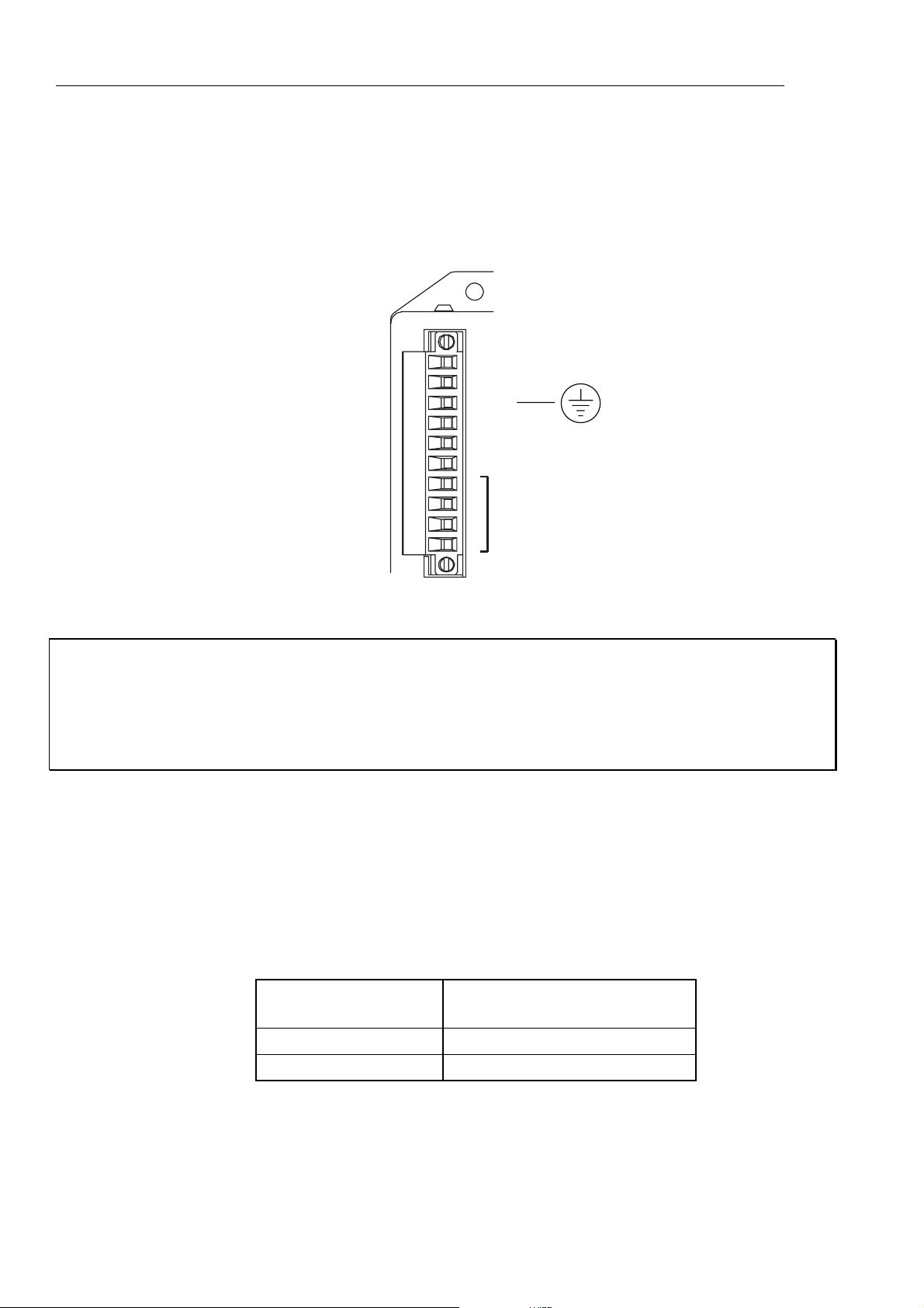
Power Supply Connections
Power drives from a DC supply derived from an isolating transformer or a DC power supply
(See Power Supply Options later in this section).
Note: Pin 10 is at the top of the connector X1 and pin 1 at the bottom.
Power & motor
10-way
connector
X1
10
+HV
9
8
7
6
5
4
3
2
1
-HV
PE
+24V DC
0V (GND 24v DC)
GND
MOTOR
CONNECTIONS
Figure 3-1. X1 Power Connections
WARNING – Possible drive damage
If you use Parker XL Series stepper drives, do not attempt to use any power wiring
harness taken from an XL drive. Although the same mating connector is used for
both an XL and a ViX, the ViX wiring is the reverse of the XL and the wrong wiring
connection will damage the drive.
Mating connector type is: Wieland 8213B/10 F OB, Part number 25.323.4053.0 (Parker part
number 0405.811).
Supply Requirements
Power the ViX drives from DC supplies as specified below:
Volts
Drive Type DC Supply Voltage
between +HV and -HV
ViX500 48V to 80V (recommended)
ViX250 24V to 80V
Table 3-1. Drive Supply Voltages
Page 18

3. ELECTRICAL INSTALLATION 11
WARNING
The drive HV supply input is not reverse polarity protected.
Reverse polarity connections will damage the drive.
Current and Capacitance
A supply must have a minimum amount of capacitance to support a drive at peak power
draw.
Drive Type DC Supply Current Supply Capacitance
ViX500 5.6A RMS
ViX250 2.8A RMS
Table 3-2. Drive Supply Currents
6600µF
3300µF
+24V Requirements
Both drive types require a +24V controller and logic supply. The supply may also be
required for an encoder and a Fieldbus Expansion Module (FEM).
Absolute voltage range 20 to 27V
Nominal drive current 250mA (excluding encoder, & FEM)
Encoder supply loading 150mA (if required)
FEM current 50mA
Safety Earth Requirements
Earth the drive using the earth pin on X1 (pin 8).
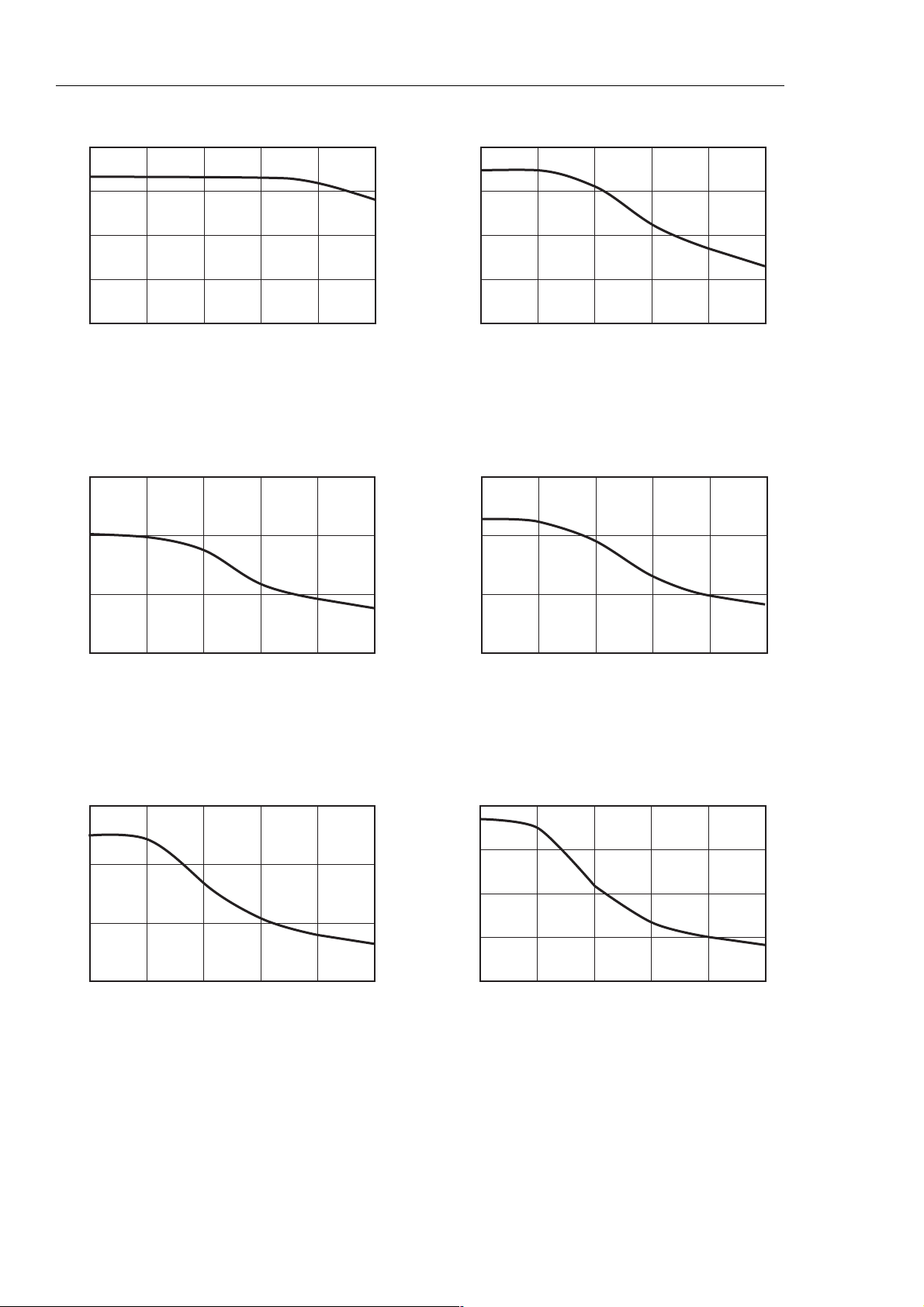
Power Supply Options
A set of torque curves (Figure 3-2) for various motor/drive combinations can be used for
calculating an applications likely power requirements.
Higher torque/current requirements will need to use the ViX500 drive and a high current
linear supply, such as the PL1100. Further power supply information is given in Appendix A.
Page 19
12 VIX IM MICROSTEPPER INDEXER DRIVE USER GUIDE
N
N
N
mNm
0.4
0.3
0.2
0.1
0
0
ViX250 with SY561
10 20 30 40 50
0.8
0.6
0.4
0.2
0
0
ViX250 with SY562
10 20 30 40 50
Speed, revs/sec Speed, revs/sec
mNm
1.5
1.0
ViX500 with SY563
1.5
1.0
ViX250 with SY871
0.5
0
0
10 20 30 40
50
0.5
0
0
10 20 30 40 50
Speed, revs/sec Speed, revs/sec
mNm
3.0
2.0
1.0
0
0
ViX500 with SY872
10 20 30 40 50
4.0
3.0
2.0
1.0
0
0
ViX500 with SY873
10 20 30 40 50
Speed, revs/sec Speed, revs/sec
Figure 3-2. Stepper Drive Torque/Speed Data
Page 20

3. ELECTRICAL INSTALLATION 13
XL-PSU Power Supply
The XL-PSU is a 250W, power factor corrected, switched mode power supply. Designed for
direct operation from world wide single phase AC input voltages, the supply is capable of
powering up to two ViX250 drives (see note 1) without the need for an EMC mains input filter
(see note 2). The use of the XL-PSU offers the following benefits:
• Auto-adapts to supplies between 95 and 264V AC
• No external EMC filter required
• Compact size
• Built-in +24V DC supply
Note 1: Check the application’s power requirements from the torque/speed curve of the
motor used.
Note 2: For drives with up to 30 metre motor leads.
For full installation instructions see the XL Power Supply leaflet 1600.300.XX.
Page 21
14 VIX IM MICROSTEPPER INDEXER DRIVE USER GUIDE
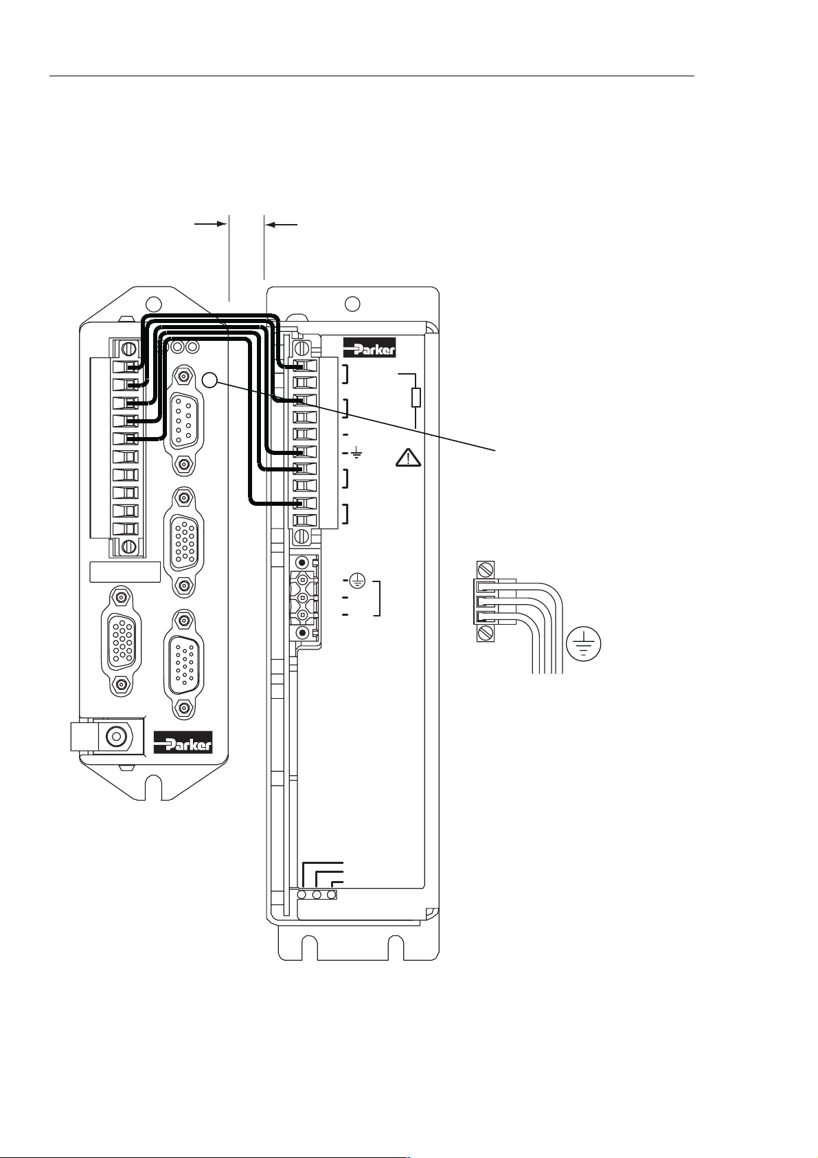
XL-PSU Supply/Drive Connections
When used to supply up to two drives the power supply can be wired as shown in Figure 3-3.
X1
10
1
ST
HV FB
X3
X4
10 mm
Mininum spacing
between drives & PSU
1
+DC (80V)
-DC
EXT. BRAKING RES.
+24V
GND
10
If the supply is positioned
this side of the drive
avoid blocking access to
D-type X3
P1
P2 mating socket
X2
MAINS
N
INPUT
X5
L
110V-230V~
50/60 Hz
250VA
P2
XL
Power
Supply
Unit
HV STATUS
BRAKING RES.
24V STATUS
Figure 3-3. XL Power Supply and Drive Connections
LN
EARTH (GND.)
The XL_PSU must
be securely earthed
Note: A kit of five connecting links is available, called ‘XL-connect’. You will need one kit for
every drive.
Page 22

3. ELECTRICAL INSTALLATION 15
XL-PSU Mounting Information
Mount the supply vertically, near the drives it will supply. Both the top 4.5mm diameter fixing
hole and the bottom two 4.5mm width fixing slots should be used.
Allow a minimum free space of 50mm both below and above its case and 10mm free space
on both sides.
Do not mount the supply above or close to other products that generate a significant amount
of heat by radiation or convection.
Page 23
16 VIX IM MICROSTEPPER INDEXER DRIVE USER GUIDE
PL1100 Power Supply
General Description
The PL1100 is a linear power supply with a rated output of 1120W (80V/14A) for use with
ViX and XL series drives. The supply requires a suitably rated transformer supplying 50V
AC RMS for the HV and 20V AC RMS for the +24V DC. The use of the PL1100 offers the
following benefits:
• Provides 80V HV and +24V DC output
• Single or three phase operation
• Built-in power dump switch
• Integral fusing
Figure 3-4 shows the PL1100 output wiring for two ViX drives. This illustrates how to route
the main HV supply separately to each drive. The lower current requirements of the +24V
logic/brake supply can allow the wiring to be linked between drives.
For full installation instructions see the PL1100 Power Supply leaflet 1600.323.XX.
ST
CAUTION
Risk of electric shock.
High voltage remains on terminals
after power is removed.
Allow 5 minutes for capacitors
to discharge.
PL1100
Power Supply
55V
AC IN
1/3 PH.
HV
REGEN
X1
MOTOR HV OUT
MOTOR 0V.
EXT. BRAKING RES.
PE
+24V DC OUT
20V AC IN
20V AC IN
LINK
FOR
SINGLE
PHASE
X2
+24V
0V
L3
L2
L1
X1
X2
ST
HV FB
10
X3
X4
1
X5
X1
10
X2
HV FB
X3
X4
1
X5
10 mm MIN
Figure 3-4. PL1100 Power Supply and Drive Connections
Page 24

3. ELECTRICAL INSTALLATION 17
EMC Installation
These EMC installation recommendations are based on the expertise acquired during the
development of compliant applications, which Parker believes are typical of the way, a drive
or drives may be used. Provided you have no special installation requirements or untypical
operating environment requirements, ViX drives will conform to current EMC Directives, as
defined at the front of this user guide.
General Requirements
ViX mounted drives, unless used with an XL-PSU, will require an EMC supply filter to meet
EMC installation compliance requirements. Mount the drive on a conductive panel which is
shared with the EMC filters. If the panel has a paint finish, it will be necessary to remove the
paint in certain areas to ensure filters and drive make a good large-area metal to metal
contact between filter case and panel.
Mount filters close to the drive and keep the supply wiring as short as practical. Attempt to
layout the wiring in a way that minimises cross coupling between filtered and non-filtered
conductors. This means avoiding running wires from the output of a filter close to those
connected to its input. Where you wish to minimise the cross coupling between wires avoid
running them side-by-side one another, if they must cross, cross them at 90° to each other.
Keep wiring supported and close to cabinet metalwork.
Recommended EMC filter types are CORCOM 6FC10 for loads up to 6A and 3VK1 for the
+24V supply up to 3A. Multi-axis systems may require higher current rated filters.
+24V Supply Connections
ViX drives not using an XL-PSU will require a logic supply of +24V DC at 250mA (nominal)
per drive. The +24V powers the controller and I/O circuits. Keeping the +24V independent
of the drive’s internal high voltage bus supply allows the option of keeping the I/O and
controller active when no main supply is present.
Connect the +24V supply to X1 pin7 and the return to X1 pin6, the total wire length, from
supply to drive, must not exceed 10m.
Connect the +24V supply 0V line to system earth (0V) at some convenient point before the
EMC filter input, as shown in the recommended EMC layout diagram, Figure 3-5.
The 24V supply to each drive should be fitted with a time-delay fuse, rated at 3A. Note: The
+24V supply used must meet the voltage requirement specification of +24V DC +10% -15%,
ripple <1V p-p.
Page 25
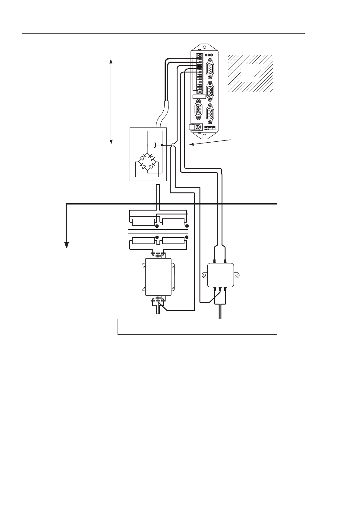
18 VIX IM MICROSTEPPER INDEXER DRIVE USER GUIDE
ST
HV FB
X1
10
X3
Lead length
restriction
(less than 1 metre)
DC Supply
X4
1
X2
X5
CABINET
BACK
PLANE
Star earth point
to the metal
backplane
Located in
the base of
the cabinet
Transformer
AC Supply
CORCOM
Figure 3-5. ViX EMC Installation
(load)
Output
6FC10
(line)
Input
Power wiring conduit
LOAD
3VK1
LINE
+-
DC 24V Supply
Page 26

3. ELECTRICAL INSTALLATION 19
Motor Connections to the Drive
The recommended wire size for ViX250IM/500IM motor cables, of length less than 20m, is
1mm2. For motor cable lengths greater than 20m (up to a maximum of 50m) use a wire size
of 2.5mm
34805), the green wire being used to provide an earth return to the drive. Termination at the
motor must be made using a 360° bond to the motor body, and this may be achieved by
using a suitable clamp. Many stepper motors are designed to accommodate an appropriate
terminal gland which can be used for this purpose.
At the drive end of the cable, a 360° connection to the screen should be made using the
P-clip provided beneath the motor connector. The P-clip needs to be firmly clamped to the
copper braid. If the connection appears loose, fold the braid back on itself to increase the
amount of braid under the clip and re-tighten.
Custom cables will require the cable insulation to be removed to expose the braided screen.
If you are using a motor cable with 2.5mm
9mm to accommodate the increased cable diameter. A ferrite absorber, with a specification
matching that of the Chomerics H8FE-1115-NC, is also required to be positioned on the
motor cable using heat shrink sleeving or cable ties. The position of the absorber should be
within 150mm of the drive. Always secure the cable using the P-clip, as shown. Do not rely
upon the connector alone holding the motor cable in place. Avoid stress on the X1
connector by hanging cables, as this may lead to connector over-heating.
2
. Use a cable containing five conductors plus the braided screen (such as Lapp
2
conductors the size of the P-clip will need to be
Make a 360° connection to the screen using one of the stainless steel or brass P-clips
supplied within the fit kit.
Size Parker part number
9mm ID 4216.101
10.7mm ID 4216.102
12.3mm ID 4216.103
Table 3-3. P Clip sizes
Three different size ‘P’ clips allow the use of a variety of motor power cables from different
manufactures.
There must be no break in the 360° coverage that the screen provides around the cable
conductors. If a connector must be used it should retain the 360° coverage, possibly by the
use of an additional metallic casing where it passes through the bulkhead of the enclosure.
The cable screen must not be bonded to the cabinet at the point of entry. Its function is to
return high-frequency chopping current back to the drive. This may require mounting the
connector on a sub-panel insulated from the main cabinet, or using a connector having an
internal screen which is insulated from the connector housing. Within the cabinet itself, all
the motor cables should lie in the same trunking as far as possible. They must be kept
separate from any low-level control signal cables. This applies particularly where the control
cables are unscreened and run close to the drive.
Page 27

20 VIX IM MICROSTEPPER INDEXER DRIVE USER GUIDE
Note that the motor cable routing within the equipment cabinet should be kept at least
300mm away from I/O cables carrying control signals.
All motor connections must be made using a high quality braided-screen cable. Cables
using a metallised plastic bandage for an earth screen are unsuitable and in fact provide
very little screening. Care must be taken when terminating the cable screen, the screen
itself is comparatively fragile; bending it round a tight radius can seriously affect the
screening performance. The selected cable must have a temperature rating which is
adequate for the expected operating temperature of the motor case.
Motor Cables
Motor cables may be ordered using the part numbers listed in Table 3-4.
Product code/Part
number
STC20-0300 3
STC20-0500 5
STC20-1500 15
Table 3-4. Motor Cables
Length (metres)
Motor Phase Contactors
We recommend that motor phase contactors are not used within the motor power cables. As
an alternative, make use of the drive’s power stage ‘enable’ control signal.
Ferrite absorber specifications
The absorbers described in these installation instructions use a low-grade ferrite material
that has high losses at radio frequencies. They therefore act like a high impedance in this
waveband. Produced by Parker Chomerics, the recommended component is suitable for use
with cable having an outside diameter up to 10mm. The specification is as follows:
Chomerics part number H8FE-1115-NC (Parker part number 0313.020)
Outside diameter 17.5mm
Inside diameter 10.7mm
Length 28.5mm
Impedance at 25MHz 80 ohm
Impedance at 100MHz 120ohm
Curie temperature 130°C (the device should not be operated near this temperature)
Page 28

3. ELECTRICAL INSTALLATION 21
Motor Selection
Usually optimum performance will be obtained when the current rating of the motor is
between 1 and 1.5 times the drive rating. Drives can be de-rated to accommodate motors
with lower current ratings (using variable MC within the MOTOR command), however the
high speed torque will be reduced.
Do not use a drive setting which gives an output current greater than the motor rating.
With 4 lead motors the bipolar rating is quoted and this should match the criteria stated
above.
With 8 lead motors the bipolar rating of the motor, which is normally quoted, refers to a
parallel winding connection. With the windings connected in series the current rating of the
motor connection will be 50% that of the bipolar rating, and the motor will give improved lowspeed torque, but reduced high-speed torque.
The ViX250IM/ViX500IM will drive motors having an inductance as low as 0.5mH and as
high as 20mH, but the recommended motor inductance range is between 0.8mH and 10mH.
Performance of the ViX250/ViX500IM is optimised for the following motor types, listed in
Table 3-5.
Motor Type Motor Rated
Current in
Amps*
SY561 4.2 1.0
SY562 4.2 2.6
SY563 6.5 1.2
SY871 4.2 1.6
SY872 6.5 1.5
SY873 8.4 1.7
SY1072 8.0 2.4
*(parallel connection)
Table 3-5. SY Optimum Motor Types
Motor Voltage Ratings
Motors with a withstand voltage rating from phase to earth of 1000V AC should be used. An
insulation withstand rating of 500V AC is acceptable if an isolating transformer with earthed
screen is used to power the system, and 0V input is earthed, as specified.
Motor
Inductance
in mH per
phase*
ViX500IM ViX250IM
✔
✔✔
✔
✔✔
✔
✔
✔
Page 29
22 VIX IM MICROSTEPPER INDEXER DRIVE USER GUIDE
Large Motors
The largest recommended motor size is a 34-frame 3-stack. Please contact Parker if
you wish to use a larger frame motor.
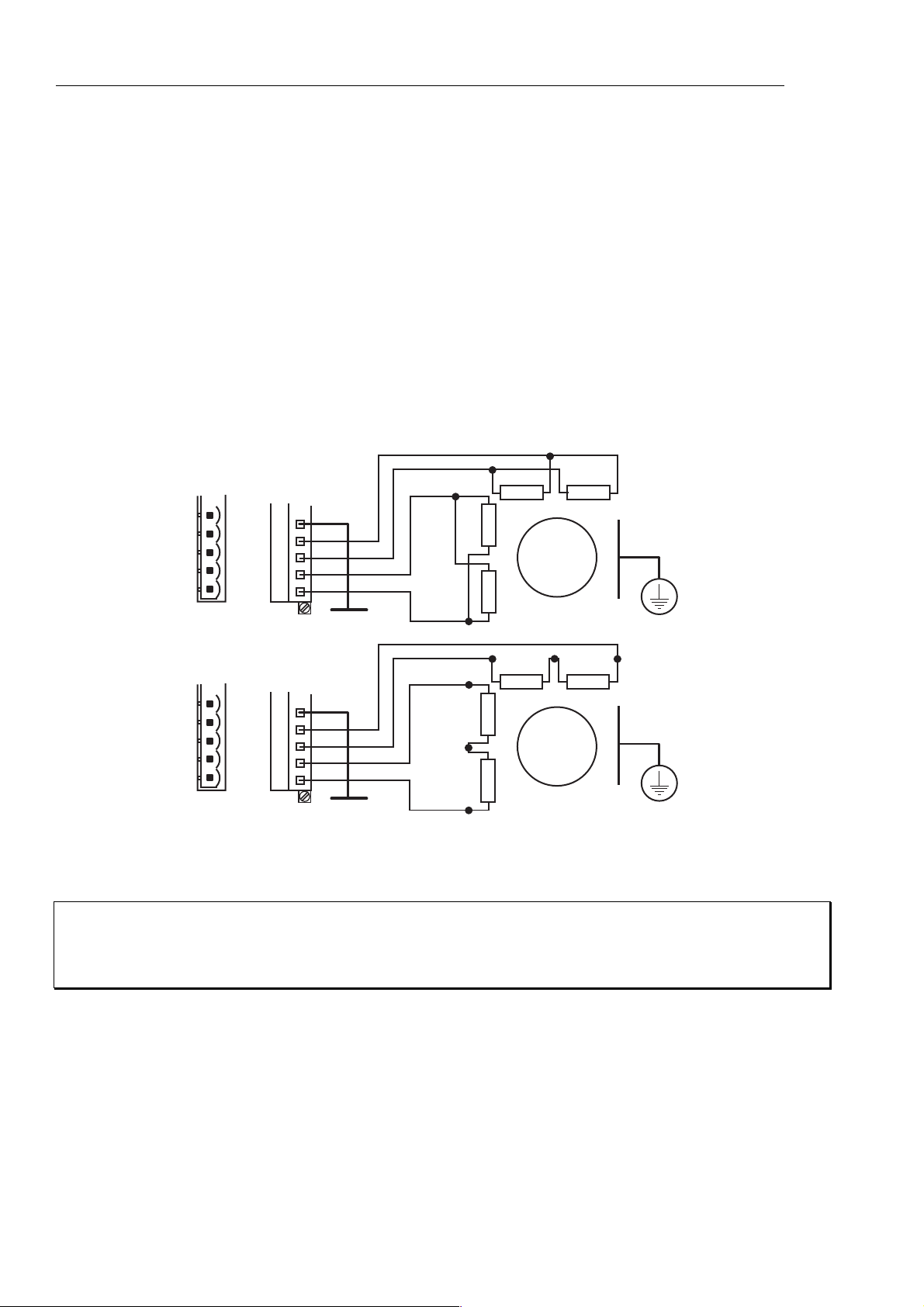
Motor Connections at the Motor
Motor connections should be made directly between the drive and motor, the use of any
switching devices, such as contactors is not recommended.
In the majority of applications the drive will be used with an eight lead motor with the
windings connected in parallel or series, as shown in Figure 3-6. Motor connections will
need to be determined from the motors data sheet or Appendix B. These are normally
identified by wire colour or terminal markings, depending upon the make of the motor.
+
-
+
MOTOR CONNECTOR
X1
5
4
3
2
1
Gnd
A+
AB+
B-
Motor case
-
+
-
+
-
MOTOR
PARALLEL
CONNECTIONS
SAFETY
EARTH
MOTOR CONNECTOR
X1
5
4
3
2
1
Gnd
A+
AB+
B-
Motor case
-
+
-
+
-
SERIES
CONNECTIONS
MOTOR
SAFETY
EARTH
+
-
+
Figure 3-6. 8 Lead Motor Connection Options
WARNING - High Temperature
The motor case temperature may exceed 70°C and should be guarded from operator
contact.
Motor Safety Earth/Ground Connection
It is recommended that the motor is independently bonded to a local safety earth point. The
safety earth lead should be at least 2.5mm
2
in area.
Page 30
3. ELECTRICAL INSTALLATION 23
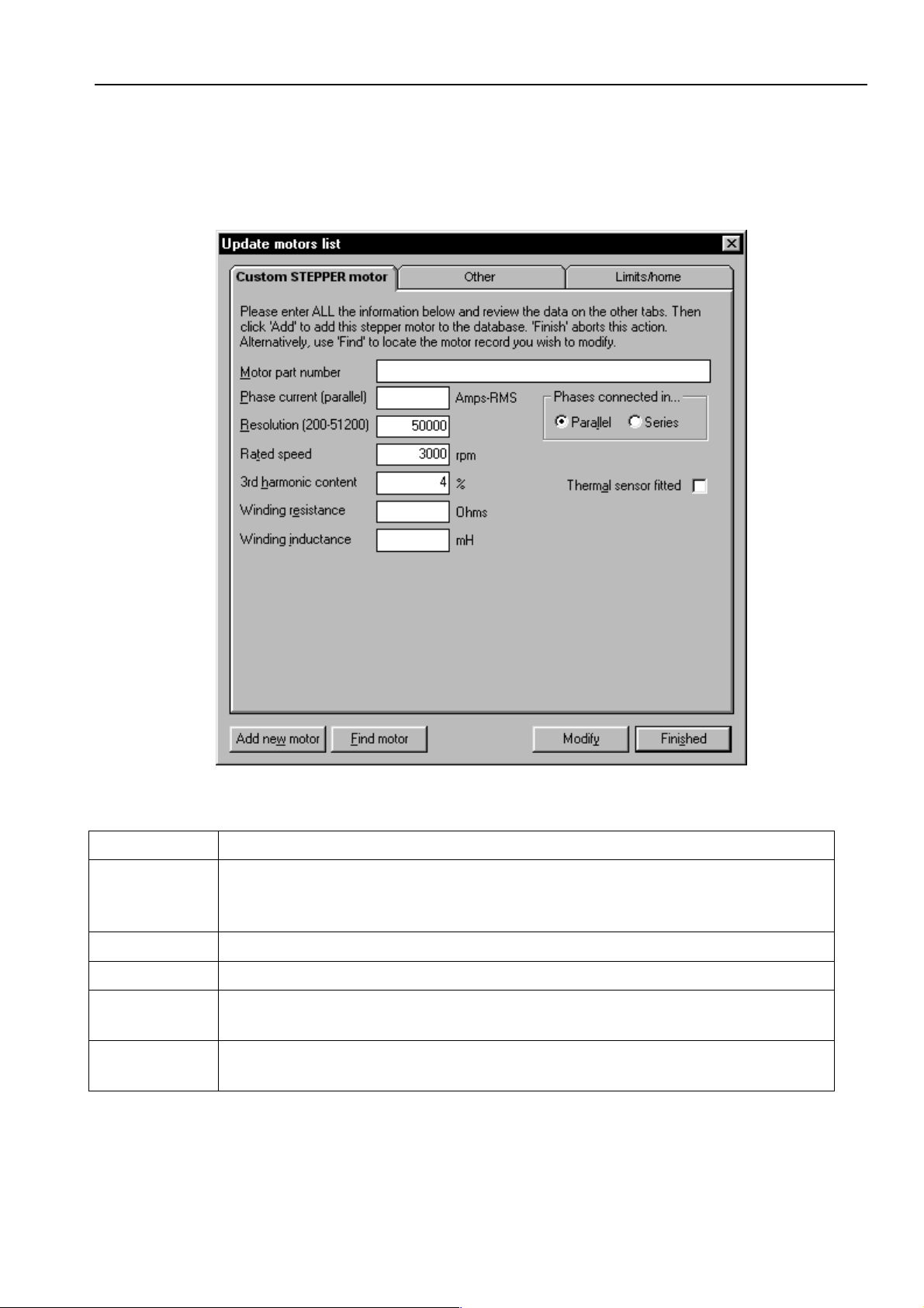
Custom Motor Set Up
Within screen 2 of Guided stepper initialisation, clicking upon the Setup custom button will
open the window shown in Figure 3-7.
Figure 3-7. EASI-V Custom Motor Configuration Window
Motor the general name/number for the motor.
Phase
current
(parallel)
Resolution number of steps per revolution
Rated speed shaft speed in rpm for a rotary stepper.
Winding
resistance
Winding
inductance
continuous current rating of the motor in Amps RMS.
resistance of a single phase winding measured line-to-line in Ohms.
inductance of a single phase winding measured line-to-line in mH.
Page 31

24 VIX IM MICROSTEPPER INDEXER DRIVE USER GUIDE
The Other Parameters Tab
Selecting the Other parameters tab gives you access to the screen shown in Figure 3-8.
Figure 3-8. EASI-V Custom Motor Other Parameters
In-position
time (IT)
Digital I/O The decimal number required by the IC system variable to configure the
input/output state of the drive.
Page 32

3. ELECTRICAL INSTALLATION 25
Figure 3-9. EASI-V Custom Motor Limits/home Parameters
Limit inputs Four radio buttons used to configure the limit inputs.
Limit
switches
Home
enabled
Home
reference
edge
Home switch Defines the type of home switch used, normally open or closed.
Direction
+ velocity
Acceleration Acceleration of the motor in revs/s/s.
Homing
mode
Selection of normally closed or normally open limit switches.
Enable/disable the HOME command.
Select the required edge of the home switch where you wish the home
position to be.
Required direction and velocity. Positive direction commands must
produce movement towards the positive limit.
Homing mode selection – see sub-section on homing for an explanation
of these modes.
Page 33

26 VIX IM MICROSTEPPER INDEXER DRIVE USER GUIDE
Motor Voltage Ratings
Motors with a withstand voltage rating from phase to earth of 1000V AC should be used. An
insulation withstand rating of 500V AC is acceptable if an isolating transformer with earthed
screen is used to power the system, and X1 pin9 (0V/GND) input is earthed, as specified.
Motor Safety Earth/Ground Connection
It is recommended that the motor is independently bonded to a local safety earth point. The
safety earth lead should be at least 2.5mm2 in area.
Short Circuit Protection
The motor outputs are protected against overload and short circuits.
Page 34

Power & Motor
X1
24-80V DC +HV
10
0V / GND -HV
9
8
Earth PE
7
24V DC
0V (GND 24v DC)
6
Motor Gnd
5
Motor phase (A+)
4
Motor phase (A-)
3
Motor phase (B+)
2
1
Motor phase (B-)
Feedback, Digital encoder
Function
X2
Feedback enc. Z+
1
Feedback enc. Z-
2
GND
3
4
Reserved
+5V output
5
GND
6
7
Feedback enc. AFeedback enc. A+
8
Reserved
9
10
Motor overtemp
Feedback enc. B-
11
12
Feedback enc. B+
Reserved
13
Reserved
14
Reserved
15
Protective Earth
PE
Power & motor
10-way
connector
Motor Earth
ME
Primary
encoder
15-way
socket
Fixing position
for motor lead
earth clip, included
in fit kit
X1
X2
1
5
10
3. ELECTRICAL INSTALLATION 27
A range of
mating connectors
are supplied, depending
upon the type of fit-kit
ordered.
ST
HV FB
X3
1
5
X4
1
1
5
6
X5
11
5
15
1
10
RS232
6
9-way
socket
9
6
11
Control/Aux I/O
15-way
socket
15
10
10
15
User I/O
15-way
plug
11
6
RJ45 connectors
8
X7 (OUT)
1
8
X6 (IN)
1
High speed
comm.
Interface
Communications
Function
X3
Rx+/Tx+ (RS485)*
1
2
Drive reset
RS232 GND
3
4
RS232 Rx
RS232 Tx
5
Rx-/Tx- (RS485)*
6
7
RS232 Tx (D loop)
8
Do not connect
+5V output
9
*requires CAN option
Control/Aux I/O
Function
X4
ANA1+ IN
1
ANA1- IN
2
0V
3
4
0V
+5V output
5
Fault output
6
Enc. A-/Step- IN
7
Enc. B-/Dir- IN
8
9
Enc. A- OUT
10
Enc. B- OUT
11
Energise/Shutdown*
12
Enc.A+/Step+ IN
13
Enc. B+/Dir+ IN
Enc. A+ OUT
14
Enc. B+ OUT
15
*Active high/low mode configurable
using system variable ES
User I/O
Function
X5
0V
1
0V
2
0V
3
4
Output 2
Output 1
5
Input 5 (limit+)
6
7
Input 4 (limit-)
Input 3 (Home)
8
9
Input 2 (Reg)
10
Input 1 (stop)
+24V
11
12
+24V
13
+24V
Output 3
14
Reserved
15
Figure 3-10. ViX Connector Pin Layout
Page 35

28 VIX IM MICROSTEPPER INDEXER DRIVE USER GUIDE
Terminal Description
X1 Connector
X1 is the main power and motor connector. Both HV, +24V and the motor phase
connections are made to X1.
Connector Type
The mating connector for X1 is a Wieland 8213B/10F, part number 25.323.4053.0 (Parker
part number 0405.811). An approval marked version of this connector has the part number
25.323.1053.0.
Connector Pin Out
Connector Pin X1 Signal Name
10 24 to 80V DC +HV
9 0V/GND -HV
8 Earth PE
7 24V DC
6 0V (GND for 24V DC)
5 Motor Earth
4 Motor phase (A+)
3 Motor phase (A-)
2 Motor phase (B+)
1 Motor phase (B-)
Table 3-6. X1 Power and Motor Connections
Motor Connections at the Drive
Refer to the EMC installation information earlier in this section.
Page 36

3. ELECTRICAL INSTALLATION 29
X2 Connector
X2 provides the primary input connections for the motor feedback device. This is the input
that should be used for position maintenance and stall detection functions.
Connector Type
Connector type is a high-density 15-way D-type socket.
Connector Pin Out
Connector
Pin X2
1 Feedback enc. Z+
2 Feedback enc. Z3GND
4 reserved
5 +5V output
6GND
7 Feedback enc. A8 Feedback enc. A+
9 reserved
10 Motor overtemp+.
11 Feedback enc. B12 Feedback enc. B+
13 reserved
14 reserved
15 reserved
Primary Encoder
Table 3-7. X2 Primary Feedback Connections
Encoder Compatibility for X2 & X4
Incremental channels Input specification
Signal format quadrature 5V differential signals (A+, A-, B+, B-) index mark (Z+, Z-).
Maximum digital encoder input frequency 2.0MHz pre quad, 8.0 MHz post quadrature.
Maximum encoder supply current 350mA.
Page 37

30 VIX IM MICROSTEPPER INDEXER DRIVE USER GUIDE
Motor Overtemperature Sensor
Standard Parker stepper motors do not use an over-temperature sensor, however when
using custom motors provision is made for the connection of either a thermal switch or
thermistor device. The following devices are supported:
• Thermik SNM130ES
• Cantherm F11 110-2-5 U106
Other ptc thermistors with a switch like characteristic are supported to DIN44081/44082.
The input requires a normally closed switch to be connected to GND on X2 pin 3 or 6.
If you use a custom motor with no overtemperature sensor fitted, make sure you leave the
‘Thermal sensor fitted’ check box un-checked in the Custom Motor Set Up screen, within
Easi-V to prevent an overtemperature fault being reported. This is the default setting in
Easi-V.
X3 Connector
X3 is the RS232/RS485 communications connector. RJ45 connectors X6 and X7 may also
be used for inter-drive communications where multi-axis systems are used.
RS485 Operation
RS485 operation is only possible on drives fitted with the appropriate FEM (Fieldbus
Expansion Module). If you require this feature please order the ViX – CM drive type.
Connector Type
Connector type is a 9-way D-type socket.
Connector Pin Out
Connector Pin X3 Function
1 Rx+/Tx+ (RS485)
2
3 RS232 GND
4 RS232 Rx
5 RS232 Tx
6 Rx-/Tx- (RS485)
7 RS232 Tx (D loop)
8 Do not connect
9 +5V output
drive reset
Table 3-8. X3 RS232/RS485 Connections
Page 38

3. ELECTRICAL INSTALLATION 31
Baud Rate
Use system variable BR to alter the baud rate of serial communications. Any change made
to the baud rate will only take effect following a save (SV) and system reset or power cycle.
Reset to RS232 Mode
To reset the drive to RS232 mode and to return to factory settings, remove power from the
drive, connect X3 pin 2 to GND and restore power.
CAUTION
This will erase ALL of your user settings and programs in volatile memory. The non-
volatile memory will not be overwritten until a save command is issued.
Terminal/PC
GND
Rx
Tx
CONN.
SHELL
Terminal RS232 socket Interface
Back of
mating plug
13
1425
PC RS232 socket Interface
Back of
mating socket
1
5
9
6
Back of
mating plug
1
Serial connector
socket
Back of
mating plug
Serial connector
plug
Drive
1
5
X3 Socket
1
5
X3 Socket
GND
Rx
Tx
CONN.
SHELL
6
9
6
9
SERIAL
2 Tx
3 Rx
7 GND
3 Tx
2 Rx
5 GND
X3
4 Rx
5 Tx
3 GND
X3SERIAL
4 Rx
5 Tx
3 GND
Figure 3-11. X3 D-type Connector RS232 Connections
Inter-drive RS232 Connections
Use the RJ45 connectors X6 and X7 to inter-connect drives, see RS232 Daisy Chain later in
this section. Always make the primary connection via D-type X3.
Page 39

32 VIX IM MICROSTEPPER INDEXER DRIVE USER GUIDE
RS232 Connecting Leads
RS232 cables can be ordered from Parker. Various lengths are available as listed in
Table 3-9.
Part Number Length
RS232-EASI-0250 2. 5m
RS232-EASI-0500 5.0m
RS232-EASI-0750 7.5m
RS232-EASI-1000 10.0m
RS232-EASI-1250 12.5m
RS232-EASI-1500 15.0m
Table 3-9. RS232 Connection Lead Types
X4 Connector
Connector X4 gives access to the following encoder input and output signals and the
differential analogue inputs. Certain input and output connections are dependent upon the
state of system variables EO (Encoder Output) and EI (Encoder Input). Encoder output
signals are not generated internally by the drive, they mirror the state of the feedback
encoder inputs (if present). Use encoder connection X2 for position maintenance and stall
detection feedback.
Connector Type
Connector type is a high-density 15-way D-type socket.
Connector Pin Out
Connector Pin X4 Encoder I/O
1 ANA1+ (input)
2 ANA1- (input)
30V
40V
5 +5V output
6 Fault
11 Energise/Shutdown_bar* (input)
*See system variable ES
Table 3-10. X4 Encoder I/O Connections
Page 40

3. ELECTRICAL INSTALLATION 33
Inputs Depending Upon the State of System Variable EI
Connector Pin
EI=0 EI=1 EI=2
X4
12 STEP+ CW+ A+
7 STEP- CW- A-
13 DIR+ CCW+ B+
8 DIR- CCW- B-
Outputs Depending Upon the State of System Variable EO*
Connector Pin
EO=0 EO=1 EO=2
X4
14 STEP+ CW+ A+
9 STEP- CW- A15 DIR+ CCW+ B+
10 DIR- CCW- B-
*Requires encoder feedback input on X2
Differential Analogue Input
The ViX stepper drive can accept a differential analogue input for use with the FRATE
command. The input circuit, shown in Figure 3-12, can interface to an external +/-10V
differential signal. Analogue to digital conversion (12-bit resolution) converts the analogue
input to a digital value for use within the drive. Read the value of the analogue input as a
count via system variable AI.
Drive
Input
impedance
200K
Note: both inputs must
be connected - cannot
be used as a single ended
input
ANA1+
ANA1-
0V
GND
+
A to D
-
Software offset controlled
by system variable AO
AI, analogue
input expressed
as a count
Figure 3-12. Analogue Differential Input
Page 41

34 VIX IM MICROSTEPPER INDEXER DRIVE USER GUIDE
Figure 3-13 shows the input characteristic.
Velocity
(rps)
Commanded
velocity
Dead band
-10V
Figure 3-13. Analogue Differential Input Characteristic
An analogue deadband can be set, using system variable ‘AB’.
_________
Energise/Shutdown
Enable the drive by allowing the input pin to float high ‘1’ or by linking the pin to zero volts,
depending upon the input’s polarity. System variable ES controls the polarity of this input.
The default state of ES (Energise Sense) requires X4 input pin 11 to be connected to 0V to
enable the drive.
Volts
+10V
The function of this input differs when in mode ‘MP’, please refer to the Command
Reference section for more details.
Page 42

3. ELECTRICAL INSTALLATION 35
X5 Connector
X5 is the user Input/Output connector.
Connector Type
Connector type is a high-density 15-way D-type plug.
Connector Pin Out
Connector Pin X5 Input/Output
10V
20V
30V
4 Output 2
5 Output 1
6 Input 5 (limit+)
7 Input 4 (limit-)
8 Input 3 (home)
9 Input 2 (registration)
10 Input 1 (stop)
11 +24V
12 +24V
13 +24V
14 Output 3
15 Reserved
Table 3-11. X5 User Input/Output Connections
Page 43

36 VIX IM MICROSTEPPER INDEXER DRIVE USER GUIDE
User Inputs
Inputs can be configured using the Easi-V graphic interface or by writing directly to the IC
system variable. By adjusting the user input configuration, you can set the input switching
level threshold and you can set the internal input resistor to be a pull-up or a pull-down.
Figure 3-14 shows the position of software switches.
'0'
'1'
4K7
24V
'1' = Pull-up
'0' = Pull-down
(default)
82K
27K
SWC
SWB
'1' = invert
'0' = non-invert
Logic inverting
network depending
upon input pull-up
pull-down state
o/c
'0'
'1' = 24V threshold (default)
'1'
'0' = 5V threshold
0V
Logic level as
reported by IS
SWA
0V
Input
Figure 3-14. User Input Circuit
User inputs are high logic level and low level logic compatible, but must be configured
as pull-down inputs when used with low-level 5V logic, since the pull-up mode always
pulls-up to +24V.
Only one input is shown above, individual inputs can be set-up on a one-to-one basis
allowing different inputs to have different threshold switching levels or different pull-up, pulldown arrangements.
CAUTION – Unexpected motor movement
De-energise the drive before making any changes to the I/O configuration.
Page 44

3. ELECTRICAL INSTALLATION 37
User Outputs
User outputs can be configured using the Easi-V graphic interface or by writing directly to the
IC system variable. By adjusting the user output configuration, you can set the output to
source or sink current. Figure 3-15 shows the output circuit.
Common IC
housing all
top-switches
for all outputs
+24V
'1' = Current source
0V
Output
'0' = Current sink
0V
Figure 3-15. User Output Circuit
User outputs are compatible with high-level 24V logic only. Each output can source
or sink 50mA.
Note: The easiest way of configuring the drive’s inputs and outputs is to use the
Easi-V graphic user interface.
Input/Output Configuration
To set-up the input and output configuration without using the EASI-V graphic interface, you
will need to write configuration patterns to the two-byte IC parameter, as shown.
aW(IC,{4 digit decimal number equivalent to a two-byte number})
Bits 8 to 12 control the switching threshold of inputs 1 to 5 (SWC setting).
Setting a bit to a ‘1’ gives a 24V switching threshold, a ‘0’ gives a 5V switching threshold.
Bit 15141312 11 10 9 8
IC
content
not
used
not
used
not
used
in_5 in_4 in_3 in_2 in_1
Page 45

38 VIX IM MICROSTEPPER INDEXER DRIVE USER GUIDE
Bits 0 to 4 control the input resistor pull-down/pull-up of inputs 1 to 5 (SWA setting).
Setting a bit to a ‘1’ sets the input resistor to be a pull-up to +24V, a ‘0’ sets the resistor to be
a pull-down.
Bits 5 to 7 controls the source/sink operation of outputs 1 to 3.
Setting a bit to a ‘1’ sources current from the +24V rail via the upper half of the output, while
setting a bit to a ‘0’ sinks current from a connected input through the lower output transistor
to 0V.
Bit 7 6 5 4 3 2 1 0
IC
content
Note:
[1] SWB is automatically set to ensure that the software will report ‘0’ for a closed input
switch and ‘1’ for an open input switch.
[2] sourcing outputs can only be used with 24V high level logic.
[3] 5V tolerant input connections must only be used with pull-down (sink) configuration as
the input pull-up always pulls up to 24V.
[4] Invalid combinations will report an error (*E), and the User Fault (UF) bit 1 is set (value
out of range).
out_3 out_2 out_1 in_5 in_4 in_3 in_2 in_1
User inputs are high logic level and low level logic compatible, but must be configured
as pull-down inputs when used with low-level 5V logic, since the pull-up always pullsup to +24V.
Example
Configure a drive with inputs in_1 and in_2 arranged as pull-down 5V threshold logic. In_3,
In_4 and In_5 as pull-up high threshold level logic, and all outputs as current sources. The
binary pattern required is:
(MSB) (LSB)
00011100 11111100
In hex. this becomes 1CFC, which in decimal is 7420
So the required command to (say) axis 3 is 3W(IC,7420)
IC default setting
The default setting for the drive is all inputs set to 24V threshold, all inputs pulled-down and
all outputs sourcing, which gives a binary pattern of 00011111 11100000, which in hex.
gives 1FE0, resulting in the decimal equivalent of 8160.
Page 46

3. ELECTRICAL INSTALLATION 39
N
Fault Output
The fault output is an independent NPN open-collector output which is normally ‘low’, active
‘high’. The output ratings are +30V maximum in the OFF condition and 15mA maximum in
the ON condition. Figure 3-16 shows the output circuit.
Drive
circuit
Fault
Output
0V
Figure 3-16. Fault Output Circuit
Limit Switches
The drive has two limit inputs, the positive limit input and the negative limit input. When
wiring the limit switches it is essential to check that a positive direction command produces
motion towards the positive limit switch .
+24V
C NEGATIVE
LIMIT
POSITIVE
MOTION
NC POSITIVE
LIMIT
Positive limit input
Negative limit input
Figure 3-17. Limit and Stop Switch Configuration
Page 47

40 VIX IM MICROSTEPPER INDEXER DRIVE USER GUIDE
RJ45 Interfaces
Positioned beneath the drive are two RJ45 communication interfaces X6 and X7. The two
interfaces provide support for Canbus, RS485 (using the Field Expansion Module) and daisy
chain ports for multi-axis RS232 connections between drives.
8
X7 RS232 daisy
1
8
1
High speed
comm.
Interface
chain output
X6 RS232 daisy
chain input
Figure 3-18. Position of Connectors X6 and X7
Page 48

3. ELECTRICAL INSTALLATION 41
FEM1 CAT5 cable colours
X6 CANopen/RS485
1 RX+/TX+ RS485 White/Orange
2 RX-/TX- RS485 Orange
3 CAN H White/Green
4 RS232 Gnd Blue
5 RS232 Gnd White/Blue
6 CAN L Green
7 RS232 Tx White/Brown
8 RS232 Rx Brown
X7
1 RX+/TX+ RS485 White/Orange
2 RX-/TX- RS485 Orange
3 CAN H White/Green
4 RS232 sense Blue
5 RS232 Gnd White/Blue
6 CAN L Green
7 RS232 Rx White/Brown
8 RS232 Tx Brown
Table 3-12. X6/X7 Input/Output Connections
CAN Bus Termination
Systems using CANopen will need to terminate the final X7 output with a 120 ohms quarter
watt resistor connected between X7 pins 3 and 6. A ready-made CAN bus RJ45 terminator
is available as shown in Figure 3-19 (Parker part number ‘ViX-RJ45-G).
50mm
pin 1
Figure 3-19. CAN Bus Terminator
Page 49

42 VIX IM MICROSTEPPER INDEXER DRIVE USER GUIDE
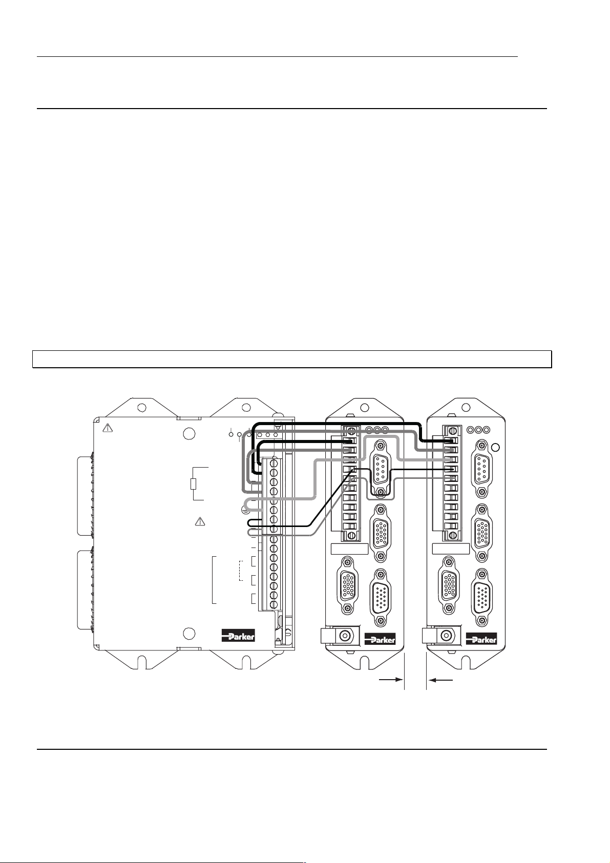
Communication Daisy Chain
Drives can be ‘daisy-chained’ for RS232/RS485* operation as shown below. Using this
arrangement the drive connected to the controlling PC, via its front panel D-type connector,
becomes axis #1. To automatically assign addresses, connect all power, motor, feedback
and communication cables then power-up all the drives, see ‘#’ command for more details.
At the controlling PC, type the following commands:
#1 ;cause the 1st drive to establish the daisy chain
in a 3-axis system the response will be #4
0SV ;save the address configuration
0Z ;reset
response should be a single check sum from axis 1
more than one check sum indicates a problem, possibly no save command
Final drive
terminates
the daisy chain
Figure 3-20. RJ45 RS232 Daisy Chain Connections
X6 rear
X7 front & X6 rear
RS232 Input from PC
X7 front
*Note for RS485 operation, the drive will need to be fitted with a FEM CAN & RS485
interface. Using the command #1(485) will switch all drives to 485 operation, which is
automatically saved.
Using the X6/X7 connections on the underside of the drive will allow the last drive in the
chain to detect that there are no more connections made to X7 which will close the daisy
chain loop back internally.
Page 50

3. ELECTRICAL INSTALLATION 43
To maintain the integrity of the EMC screening, all RS232 and RS485 connections must be
made via the drive’s X3 D-type connector.
RJ45 Connecting Leads
RJ45 link cables can be ordered from Parker. Various lengths are available as listed in
Table 3-13.
Part Number Length
VIX-RJ45-0025 0.25m
VIX-RJ45-0050 0.5m
VIX-RJ45-0075 0.75m
VIX-RJ45-0100 1.0m
VIX-RJ45-0200 2.0m
Table 3-13. RJ45 Connection Lead Types
Note: Individual cables that are within the RJ45 daisy chain system must not exceed a length
of 2m. Where a cable length greater than 2m is required between axes, a fully screened
connection should be made via connector X3.
Page 51

44 VIX IM MICROSTEPPER INDEXER DRIVE USER GUIDE
Page 52

4. CONTROL OF VIX DRIVES 45
4. Control of ViX Drives
Overview
This section introduces you to the operation of the ViX stepper drive, the implementation of
motion control moves and the way commands are used. Basic controller operation is
described together with the code structure. How system information is signalled via system
variables and the use of various flag registers for status and fault reporting are described.
Both basic and advanced motion control functions are covered including elements of event
driven code used for fault reporting and registration.
Controller Operation
ViX intelligent drives have an integrated controller which can be driven directly by a PC over
a serial link, or programmed to respond to code selected by event triggers or user
instructions.
Direct Mode
Direct operation of the controller over a serial link can be used for program
development/downloading purposes or direct on-line control from an industrial PC or PLC.
When used directly the controller will accept commands prefixed with the drive’s address
and will action the commands as they are received. In direct mode any controlling
application program is stored in a remote location and is only downloaded to the drive when
required.
Programmed Mode
This mode allows a program stored within the drive to control operations. The program can
be written off-line on a PC and then downloaded to the drive via a serial link. The application
program is stored within the drive and is automatically invoked at power up provided it is
enabled by the <a>ARM1X command and the program has a START label. Alternatively,
you could directly issue a <a>GOTO(START) command.
Code Structure
You write program code as a series of blocks. Each code block has a unique label at the
beginning and is terminated with an END label (block delimiter). The use of labels allows the
code structure of the form illustrated in Figure 4-1, which shows the block nature together
with an example of code.
Declare
Declare every label used in a program, apart from START, REG, NOREG and FAULT that
have been pre-declared. If a label is declared, but not defined, a runtime error will be
signalled when it is called.
Note: START, REG, NOREG and FAULT are all reserved labels.
You can only declare labels in the command line at the start of a program or within the
START code. The choice is between memory efficiency and the retention of declared labels
Page 53

46
during up-loading/down-loading of programs. Declaring labels in the command line, before
any START code, makes the most efficient use of the available memory. If you then up-load
the program to a PC and later down-load the same program the declarations will have been
lost. To retain declared labels you must declare them in the START code, this allows a
program to be up-loaded and down-loaded without loss of declared labels, although more
memory will be used. Despite the greater amount of memory being used, it is safer to make
the declarations within the START label as there is less chance of forgetting to declare parts
of the code.
Example of DECLARE being used in the command line:
VIX IM MICROSTEPPER INDEXER DRIVE USER GUIDE
1K ;Kill or stop any program currently running
1CLEAR(ALL) ;Erase all existing programs
1DECLARE(MAIN) ;Declare labels
1DECLARE(MOVE1)
1DECLARE(MOVE2)
.
.
Example of DECLARE being used following the START label:
1K ;Kill or stop any program currently running
1CLEAR(ALL) ;Erase all programs
1START:
1DECLARE(MAIN) ;Declare labels
1DECLARE(MOVE1)
1DECLARE(MOVE2)
.
1END
Labels
Labels consist of up to 5 upper case alphanumeric characters terminated with a colon (:), but
a label must begin with an alpha character. Choose a name that is relevant to the operation
being performed, or a system label name.
To terminate a code block use ‘END’ (no colon).
You can use up to 20 labels, although four of these have already been allocated to START,
REG, NOREG and FAULT, leaving sixteen for general use.
Label Execution
By using the label select command (LSEL), labelled code blocks can be triggered by a digital
pattern appearing on certain user inputs. The command defines the user inputs to be used,
the style of code detected (BCD or binary) and the manner in which the code is executed
(continuous or re-trigger).
Enable the LSEL command using its on/off parameter to allow input selection of labels.
Page 54

4. CONTROL OF VIX DRIVES 47
Structure
The code example of an absolute positioning move shown in Figure 4-1 demonstrates how
to write code that follows the block structure. Use the start code to initialise the drive:
Start code and
Initialisation
Main
Program
Block 1
Example:
1START: ; start label definition
1DECLARE(MAIN) ; declare labels
1DECLARE(MOVE2) ; declare move 2
1LIMITS(3,0,0) ; configure limits.
1GOTO(MAIN) ; goto main program
1END
Block 2
Block 3
Figure 4-1. Program Structure
1START:
1DECLARE(MAIN)
1DECLARE(MOVE2)
1LIMITS(3,0,0)
1GOTO(MAIN)
1END
1MAIN:
1PROFILE2(40,10,-48000,25)
1GOSUB(MOVE2)
1END
1MOVE2:
1W(PA,0)
1MA
1USE(2)
1G
1END
Use the MAIN part of the program to define profiles and to control the order of moves:
1MAIN: ; main label definition
1PROFILE2(40,10,-48000,25) ; define move parameters
1GOSUB(MOVE2) ; jump to label move 2
1END ; end of label definition
Page 55

48
Finally, call individual moves from the main part of the program:
Note: PROFILE2 defined in the main part of the program has the following characteristics:
ACCELERATION 40rps² , DECELERATION 10rps², DISTANCE 48000 steps (12 REVS
MOVE), NEGATIVE DIRECTION , VELOCITY 25 rps.
In small programs, the start code can be combined with the main part of the program. For
experienced X-code users, the shorter blocks of code in the example above, accessed via
subroutines, is the equivalent of a sequence.
A second example illustrates the code required for an incremental move. Here the START
and MAIN code blocks have been combined within the START block:
VIX IM MICROSTEPPER INDEXER DRIVE USER GUIDE
1MOVE2: ; define program label “move2”
1W(PA,0) ; zero position absolute
1MA ; absolute positioning move
1USE(2) ; use motion profile 2
1G ; execute move
1END ; end of program move 2 definition
1START: ; start label definition
1DECLARE(MOVE1) ; declare move1 label
1LIMITS(3,0,0) ; configure limits (disable, n/c).
1PROFILE1(80,20,24000,20) ; define move parameters
1GOTO(MOVE1) ; transfer to label move 1
1END ; end of label definition
1MOVE1: ; define program label.
1MI ; incremental positioning move
1USE(1) ; use motion profile 1
1G ; execute move
1END ; end of program move 1 definition.
Note: [1] DEVICE ADDRESSING IS REQUIRED FOR ALL COMMANDS
[2] PROFILE1 has the following characteristics:
ACCELERATION 80rps² , DECELERATION 20rps², DISTANCE 24000 steps (6 REVS
MOVE), POSITIVE DIRECTION , VELOCITY 20 rps.
Page 56

4. CONTROL OF VIX DRIVES 49
LOOP Command
The block structure of the code lends itself to performing repetitive operations, using the
LOOP command. The command can be used to call a particular labelled block of code for
either a specified number of times or continuously.
An example using the LOOP command is given below, again the START and MAIN code
blocks have been combined within the START block:
1START: ; start label definition
1DECLARE(LOAD) ; declare label
1LIMITS(3,0,0) ; disable limits
1PROFILE3(100,50,4000,35) ; define move parameters
1MI ; set mode to incremental
1LOOP(LOAD,6) ; repeat the load unload 6 times
1END ; end of label definition
1LOAD: ; define program label load
1USE(3) ; use motion profile 3
1O(XX0) ; ensure o/p 3 is off
1T1 ; wait for 1 sec delay
1G ; execute move
1O(XX1) ; turn on o/p 3
1T1 ; wait for 1 sec delay
1END ; end of label definition
Page 57

50
Reserved System Labels
Certain pre-defined labels are recognised by the controller as containing code used for
common operations. If event triggered code is enabled (ARM1), the code entered for these
common operations will be automatically run when the event occurs.
System labels have the following names:
START: specifies the power on code, run using the ARM1 command
FAULT: specifies the code that is to be run when a fault occurs
REG: specifies the code to be run when a registration mark is detected within the
NOREG: specifies the code to be run when a registration mark is not detected within the
Note: If necessary, these labels can be used for other purposes, but cannot be re-named.
VIX IM MICROSTEPPER INDEXER DRIVE USER GUIDE
registration window
registration window
Fault Label
Use the pre-declared label named FAULT to identify a block of code that is executed when a
particular problem (fault) has been detected. The code following the FAULT label needs to
change the state of an output, to indicate a fault has occurred and then go on to possibly
diagnose the problem. Once the problem has been corrected, the FAULT code will need to
detect an external ‘reset’, by monitoring a designated input and then execute an ON
command to clear the FAULT. At the end of the FAULT code a GOTO(START) can be
issued to restart the program. This style of programming will always ensure that once a
fault is detected the drive will stop and will not start again until commanded to do so.
Before the code following a FAULT label can be executed certain conditions must be met,
these are:
• FAULT must be defined
• ARM must be set to enable a FAULT label
This means FAULT label code must be present and the ARMX1 command exists at the
beginning of the code.
Page 58

4. CONTROL OF VIX DRIVES 51
The conditions under which the FAULT label is called will vary depending upon the fault itself
and the condition of various other commands and command parameters. An exact
description is presented in Table 4-1. However, in general, a FAULT label will be called
given any one of the following conditions:
• An attempt to go home further onto a limit is made and the limit is enabled.
• An attempt to go further onto a limit is made with no fault label currently
running, the limit configuration is stop on limit and the limit is enabled.
• A limit is hit during motion and the move is not a go home, a fault label is not being
run, the limit configuration is stop on limit and the limit is enabled.
• A drive fault has occurred, but no drive programming is taking place.
• When it is called from a GOTO, GOSUB or LOOP command*.
*Note: in this case a FAULT has not actually occurred, consequently the FAULT label will be
called irrespective of the state of the ARM command.
Table 4-1 summarises the conditions necessary for the FAULT label to be called. The
FAULT label will not be called when any one of the following conditions occur:
• There is an error whilst sending a command
• There is a general run time error with the program
• The program memory area becomes full
• A label is attempted to be run when it does not exist
• The transmit buffer or receive buffer suffer an overflow
Command & parameter conditions
Fault
Condition
G onto a limit Y N/A Y Y Y Y N/A
Hit limit Y Y Y Y Y Y N/A
Drive fault Y N/A Y N/A N/A N/A Y
GOTO Y N/A N/A N/A N/A N/A Y
GOSUB Y N/A N/A N/A N/A N/A Y
LOOP Y N/A N/A N/A N/A N/A Y
FAULT
label
defined
NotGHFault
ARM
bit
Limit is
enabled
Not
running
fault
label
Limit
decision
is stop
program
execution
Not
program
-ming
the drive
Table 4-1. Conditions Required to Call a Fault Label
Page 59

52
Example
The following example shows the use of a FAULT label within a program.
VIX IM MICROSTEPPER INDEXER DRIVE USER GUIDE
1ARM11 ;enable auto-run on power-up & enable fault routine
1SV ;save the settings
1START: ;start of program
1ARM11 ;re-enable auto-run & fault in case ‘K’ command sent
.
<initialisation commands>
.
1O(1XX) ;turn on output 1 - drive OK
.
<main process commands>
.
1END
1FAULT: ;fault routine
1O(0XX) ;turn off output 1 - drive fault
.
<diagnostic code - if required>*
.
1TR(IN,=,1XXXX) ;wait for input 1 to become active (RESET)
1ON ;clear fault
1GOTO(START) ;run from start of program again
1END
*Note: An example of diagnostic code is given in the sub-section entitled Conditional Code
later within this section.
Page 60

4. CONTROL OF VIX DRIVES 53
Start Label
The system label START: introduces the drive’s setup and initialisation code. With ARM
enabled the code is automatically executed at system start-up*. Consequently the code
needs to be saved with ARM1X set. If you save a program with ARM0X set, the start-up
code will not run and the controller will only respond to serial input commands.
*Unless a drive fault is pending and a fault routine is defined and armed.
Start Label Example:
1START:
1”RUNNING”
-
-
1END
1FAULT:
1”FAULT”
1TR(IN,=,1XXXX)
1GOTO(START)
1END
1ARM01 ;enable fault routine only
1SV ;save all settings
If you cycle the power to the drive the “START” routine will not automatically run. To start it
you would have to type in 1GOTO(START). However, the “FAULT” routine will run if a fault
occurs
Entering the following code:
1ARM11 ;enable auto run on “START”
1SV ;save all settings
The “START” routine should automatically run on the next power-up.
Page 61

54
VIX IM MICROSTEPPER INDEXER DRIVE USER GUIDE
Use of the LSEL Command
You can let user inputs call programmed routines by the use of special label names and
associated user input numbers. By including the code you wish to action, following a predefined input label, will enable your code to be run when the defined user input is activated.
For example, to select one of three labels using two user inputs, the code would be:
1START:
1CLEAR(ALL) ;clear memory
1DECLARE(L1) ;declare label 1
1DECLARE(L2) ;declare label 2
1DECLARE(L3) ;declare label 3
1LSEL1(0,2,1) ;define inputs and code
1A20 ;set acceleration
1V5 ;set velocity
1O(000) ;set all outputs low
1END
1L1: ;label 1 code
1O(1) ;set output 1 high
1D1000 ;set distance to 1000 steps
1G ;move 1000 steps
1T1 ;wait for 1 second
1O(0) ;set output 1 low
1END
1L2: ;label 2 code
1O(01) ;set output 2 high
1D-2000 ;set distance to -2000 steps
1G ;move -2000 steps
1T1 ;wait for 1 second
1O(00) ;set output 2 low
1END
1L3: ;label 3 code
1O(001) ;set output 3 high
1D3000 ;set distance to 3000 steps
1G ;move 3000 steps
1T1 ;wait for 1 second
1O(000) ;set output 3 low
1END
Note: The routine will only run when it receives a valid input pattern corresponding to the
numbered label names.
Page 62

4. CONTROL OF VIX DRIVES 55
Upon receipt of a valid numeric input pattern the controller runs the associated routine. For
example, binary pattern 3 causes routine L3 to run. This routine must finish (reach the END
command) before the inputs can be automatically scanned again. The state of the inputs is
presented to the controller as a parallel bit pattern. Invalid binary patterns (for non-existent
labels) are ignored.
When using the label selection function you must be aware that altering any basic operating
parameters, such as velocity, in a routine will change the value used in subsequent routines.
Consequently, you will need to define fully the move required in each subroutine block. This
can be arranged by the USE command.
System Variables
System variables are named variables held within the drive’s controller that are used for
storing a variety of system values and settings. Read system variables using the Report
system parameter (R command), but note, you can only write to certain variables using the
Write (W command).
Certain system variable values may be tested using the IF command. This allows
conditional branching within the program code, enabling equal to, not equal to, greater than
or less than decisions to be made. Wait for trigger (TR command) can also test certain
system variables by delaying code execution until the value of a system variable matches
some stored number or string within the program. Refer to the later section on conditional
code.
Page 63

56
VIX IM MICROSTEPPER INDEXER DRIVE USER GUIDE
Table of System Variables
Table 4-2 lists system variables in alphabetic order together with their read/write status and
range of values stored.
Var Name R W Range/default value
AB Analogue
Deadband
AI Analogue Input Y N -2047 to +2047
AO Analogue Offset Y Y -2047 to +2047, default = 0
BR BAUD rate Y Y 9600 or 19200 bits per second (9600 default)
BU Buffer usage Y N 0 to 100% of program buffer used
CQ Command queuing Y Y 1= Pauses until move complete (default)
DC Damping
Configuration
DF Drive Fault status Y N See below:
DF1 Drive Fault status Y N First byte of 32-bit DF variable
DF2 Drive Fault status Y N Second byte of 32-bit DF variable
DF3 Drive Fault status Y N Third byte of 32-bit DF variable
DF4 Drive Fault status Y N Fourth byte of 32-bit DF variable
EI Encoder Input Y Y 0=step/dir, 1=cw/ccw, 2=quad ABZ, de-energise drive
EM Encoder count per
rev.
EO Encoder signal
Output
EQ Echo Queuing Y Y 0=normal, 1=wait for <CR>, 2=cmd response only
ES Energise Sense Y Y Sets the sense of the external enable/shutdown_bar
EX Comms. Response
Style & Echo
Control & Physical
Interface (RS232)
Y Y 0 to +255, default = 0
0= continuous execution
Y Y 0 = settling time damping OFF (default)
1 = settling time damping ON
to change
Y Y 1 to 4200000 (default 4000)
Y Y 0=step/dir, 1=cw/ccw, 2=quad ABZ, de-energise drive
to change
signal
0=low signal to enable
1=high signal to enable
Y Y 0= speak when spoken to, echo off, default for RS485
1= speak whenever, echo off
2= speak when spoken to, echo on
3= speak whenever, echo on, default for RS232
Table 4-2. List of System Variables
Page 64

4. CONTROL OF VIX DRIVES 57
Var Name R W Range/default value
FB Fieldbus Baud Refer to CANopen user guide
FC Fieldbus Control Refer to CANopen user guide
FN Fieldbus Node ID Refer to CANopen user guide
FP Fieldbus Protocol Y Y Refer to CANopen user guide
HF Home Final
velocity
IC Input/Output
Configuration
IN Inputs (on drive) N N Local drive inputs 1 to 5, same format as IS command
INn Inputs (expansion) N N Fieldbus expansion inputs, IN1=bank1, IN2=bank2.
IP In Position flag Y N 1= In position or 0= not yet in position
IT In Position Time Y Y 1 to 500mS, default=10mS
MS Motor Standby Y Y Range 10% to 100% of programmed current
MV Moving Y N Flag 1= moving or 0 = not moving
PA Position Actual Y N* -2,147,483,648 to 0 to 2,147,483,647
PE Position Error Y N* +/- 65535
PF Position Following Y Y -2,147,483,648 to 0 to 2,147,483,647
PI Position
Incremental
PM Position Master Y Y -2,147,483,648 to 0 to 2,147,483,647 Note: a write to
PR Position
Registration
PS Position
Secondary
PT Position Target Y Y -2,147,483,648 to 0 to 2,147,483,647 Trajectory
RB Ready/Busy flag Y N Flag 0= ready or 1= busy
RM Registration Move Y N Flag 1= reg move in progress
RV ReVision of
software
SC S Curve
configuration
SN Serial number Y N reserved
Y Y Sets the final velocity of the home move
Range: 0.001 to 5.0 rps (default 0.1)
Y Y Input pull-up/down, output source/sink configuration
0 to 8191 default:8160
(default 50%)
Y Y -2,147,483,648 to 0 to 2,147,483,647
PM sets the modulus
Y N The primary (X2) feedback position (PA) on the last
active transition on input 2 (start of valid REG move).
Range: -2,147,483,648 to 0 to 2,147,483,647
Y N The PM count position on the last active transition on
input 1 (falling edge viewed using IS).
Range: -2,147,483,648 to 0 to 2,147,483,647
generator open loop target position
0 = not doing reg move
Y N x.yy major.minor
Y Y 0 = S curve accel/decel disabled (default)
1 = S curve accel/decel enabled
Table 4-2. List of System Variables (Continued)
Page 65

58
Var Name R W Range/default value
ST Status of indexing Y N See below
ST1 Status of indexing Y N First byte of 32-bit ST variable
ST2 Status of indexing Y N Second byte of 32-bit ST variable
ST3 Status of indexing Y N Third byte of 32-bit ST variable
ST4 Status of indexing Y N Fourth byte of 32-bit ST variable
TT Trigger Timeout Y Y Optional timeout for trigger command 0-65 seconds in
UF User program
UF1 User Fault Status Y N First byte of 32-bit User Fault status word
UF2 User Fault Status Y N Second byte of 32-bit User Fault status word
UF3 User Fault Status Y N Third byte of 32-bit User Fault status word
UF4 User Fault Status Y N Fourth byte of 32-bit User Fault status word
VIX IM MICROSTEPPER INDEXER DRIVE USER GUIDE
0.01 increments. User status bit 8 is set to indicate
timeout occurred before trigger condition met. Bit is
clear if trigger condition met before timeout. The
default time is = 0.00 (no timeout).
Y N See below
Fault status
*Can be set to 0 only.
Table 4-2. List of System Variables (Continued)
AB, AI and AO Description
AB controls the dead band and AO the offset of the differential analogue speed control input.
See Differential Analogue Input in the Electrical Installation section.
BR Description
This sets the Baud rate of serial communications. Enter the required Baud rate directly, for
example aW(BR,19200) to set the rate to 19200. You will need to save this setting and then
reset the drive (Z command) or cycle the power before the change will take effect.
BU Description
Gives the total percentage of program buffer usage, unlike an aDECLARE that gives the
percentage of buffer room for each label, subroutine.
Page 66

4. CONTROL OF VIX DRIVES 59
CQ Command Queuing
Enable command queuing in mode incremental/absolute to buffer each command waiting for
the previous command to complete, before issuing the next. In certain circumstances,
disable this sequential operation, for example if you need to generate a trigger pulse part
way through a move. Normally, the move would complete before trigger command
execution, but by disabling command queuing, the trigger command becomes immediate
and will operate upon meeting the required trigger conditions.
For example, the following code would allow output 1 to signal PA is greater than 10000
before finishing the move.
1MAIN: ;define label
1MI ;mode incremental
1W(CQ,0) ;enable continuous execution of commands
1G ;go
1TR(PA,>,10000) ;trigger when position actual becomes greater than 10000
1O(1) ;output 1
1TR(IP,=,1) ;wait for move to finish
1W(CQ,1) ;enable command queuing again
1END
DC Damping Configuration
Selecting DC gives a faster settling time by d amping oscillations (ringing) of the motor shaft.
Under certain conditions, such as use with low current motors, the activation of the damping
circuit can lead to an increase in the audible noise of operation. However, we recommend
the use of DC for highly dynamic operations.
DF Description
See drive fault bit description in Reporting the Status of Variables.
EO Description
When an encoder is connected to the primary feedback input on X2, you may use the
encoder outputs (connector X4) to supply a step-direction or step-up/step-down signal for
use by another drive. System parameter EO determines the output as defined in
Table 4-3. Note: The source of these pulses is X2 primary encoder, they are not generated
from within the drive’s indexer. Before changing the system variable EO it is necessary to
de-energise the drive.
X4 EO=0 EO=1 EO=2
14 STEP+ CW+ A+
9 STEP- CW- A15 DIR+ CCW+ B+
10 DIR- CCW- B-
Table 4-3. Encoder Output Configuration
Page 67

60
EI Description
System parameter EI, controls encoder inputs (connector X4) as defined in Table 4-4.
EQ Description
VIX IM MICROSTEPPER INDEXER DRIVE USER GUIDE
X4 EI=0 EI=1 EI=2
12 STEP+ CW+ A+
7 STEP- CW- A-
13 DIR+ CCW+ B+
8 DIR- CCW- B-
Table 4-4. Encoder Input Configuration
CAUTION
De-energise the drive before changing EI and EO.
Echo queuing (EQ) is a system variable that can be useful for multi-axis control programs
where you need to send and receive messages from individual drives controlled from a PC.
The variable controls the way messages are echoed and its use prevents corruption of
commands by system response messages. In a normal multi-axis system, commands from
the main controller are, in turn, echoed from drive to drive throughout the system and can be
finally returned to the main controller. If a command is transmitted whilst a drive is supplying
a response the two messages will interact, effectively destroying one another. Setting EQ to
mode 1 prevents a drive from issuing a response until it receives a carriage return, thereby
delaying its response until it finishes receiving. This stops the corruption of messages, which
can now be read back in a complete form.
EQ can only be used with a report or write command, as follows:
R(EQ) reads the current setting of the system variable.
W(EQ, 0 - 2) sets the EQ system variable to operate in mode 0, 1 or 2.
Mode 0 sets the standard operating mode where characters are echoed as they are sent.
Mode 1 does not allow any characters to be echoed until a carriage return is sent. This
prevents complete messages from being split if a data collision occurs.
Mode 2 allows only the response from a command to be sent, not the command itself. This
minimises the amount of data being transferred and therefore helps to reduce the chance of
a transmit buffer overflow.
Note: The set address command (#) will be echoed irrespective of the state of the echo
queuing variable.
Page 68

4. CONTROL OF VIX DRIVES 61
ES Description
System variable ES controls the required polarity of signal on the enable/shutdown_bar input
(X4 pin 11). The default value of ES is zero (ES=0), therefore to enable the drive connect X4
pin 11 to X4 pin 4 (0V). With ES=1 X4 pin11 may be left open circuit to enable the drive. To
energise the drive, the drive must be enabled and the ON command issued. The function of
this input differs when in mode ‘MP’, please refer to the Command Reference section for
more details.
EX Description
System variable EX controls the style and protocol of the drive’s serial communications link.
IP, IT and MV Description
System flag variables IP (In Position) and MV (Moving) together with variable IT (In position
Time) interact with one another as shown in Figure 4-2. The MV flag is only high whilst
commanded motion is taking place. The IP flag can only go high once movement has
stopped and the IT timer value has timed-out. Consequently you need to set IT to a time
long enough to ensure velocity variations (ringing) has ceased.
Velocity
(revs/sec)
MV
main move
0
1
0
APPROACHING
POSITION
ERROR
RINGING
Time, seconds
IT
IP
1
0
Figure 4-2. Interaction of MV, IP, & IT
Page 69

62
You do not have to wait for the IP flag to be set at the end of every move, but its use
improves positioning accuracy.
Example Use this code after each G command to improve positioning.
HF Description
HF sets the final home velocity when you perform a GH command.
VIX IM MICROSTEPPER INDEXER DRIVE USER GUIDE
1MI ; mode incemental
1W(CQ,0) ; turn off command queuing
1G ; start the move
1T0.1 ; wait 100ms
1IF(MV,=,1)
1”Moving”
1TR(IP,=,1)
1”Stopped”
1W(CQ,1) ; re enable command queuing
IC Description
See IC System Variable in the Electrical Installation section.
IN Description
The IN system variable is equivalent to the IS command, but allows individual inputs to be
tested using IF and TR commands during conditional coding.
For example:
The following test looks for input 1 low and input 3 high.
IF(IN,=,0X1XX)
Where X=don’t care.
INn Description
The INn system variable is used to define a particular bank of inputs when used with
Fieldbus input expansion modules.
MS Description
When the motor is stationary, reduce its current to minimise heating or to conserve power.
MS sets the reduction in current as a percentage of the programmed current (the value set in
the MOTOR command). When selected, the drive will switch to standby 25mS after the last
motor step.
Motor standby current reduction is capped at a value of 70% of the drive’s maximum output
current. Consequently, if you attempt to set an MS value greater than 70 the current
reduction value will always be equal to 70% of the drive’s maximum output current. For
example, using a ViX500 (max. output current of 5.6A) and setting MS to 90 will give a
current reduction value of 4A (70% of 5.6A).
Page 70

4. CONTROL OF VIX DRIVES 63
PA Description
PA reports the actual position of the motor shaft, assuming a primary encoder is fitted.
Although PA is marked as being read only it will accept the value 0 to be written to it for
resetting purposes. If you perform a W(PA,0) system variables PF, PE and PT will also be
set to 0.
PE Description
PE reports the position error, that is, the difference between PT and PA.
PF Description
PF reports the position fed-back by a remotely mounted encoder for following applications.
This is the position demanded by the following input. Counts are only recorded when
following is enabled and at the scaled rate, this means if the scale is -50% and 4000 counts
are received by the drive, PF will read –2000.
PI Description
PI reports the distance moved by the last move (G) command.
PM Description
PM reports the number of counts received from power-on by the following input. No scaling
is applied and PM counts regardless of following being on or off. Writing a number to PM
sets the modulus for count wrapping. That is, writing a specific number of counts to PM sets
the count required before the drive re-starts counting from zero again. This is useful if you
wish to know the position of the motor shaft as an arbitrary count.
For example writing a count of 4000 to PM means that for every shaft rotation a new count of
0 to 3999 is started (until the absolute count limit is reached). By reading PM, a count will be
returned that is somewhere between 0 and 3999, the exact value being an indication of the
instantaneous shaft position.
PR Position Registration Description
PR always reports the position of the motor from the primary feedback (X2 connector) signal
on the last active transition on user input 2. The signal is only active at the start of a valid
REG move.
PS Position Secondary Description
PS reports the position of the following input from the secondary feedback (X4 connector)
signal on the last active transition on user input 1.
PT Description
PT reports the open loop target position of the motor, that is, where you have commanded
the motor to move to.
RB Description
Reports the state of the controller as being ready or busy. While executing a program or
subroutine the controller is busy.
Page 71

64
VIX IM MICROSTEPPER INDEXER DRIVE USER GUIDE
RM Description
Reports a 1 if a registration move is being actioned.
RV Description
Reports the revision of software being used by the controller.
SC S-Curve configuration
To reduce the amount of jerk (rate of change of acceleration or deceleration) within a move,
enable SC. When enabled, this variable smoothes-out rapid changes of acceleration, as
shown in Figure 4-3.
Trapezoidal S-Curve
Velocity
Accel
Decel
Maximum Jerk
Time
Time
Velocity
Accel
Decel
Less Jerk
Time
Time
Figure 4-3. S Curve Correction of Moves
To achieve this type of S curve correction an average acceleration value is used which is set
at half the value of the maximu m acceleration. In all cases, the value of AA will be used for
acceleration and deceleration. If a value of AD is set that is not equal to AA, then the value
of AA will be used for all acceleration and deceleration settings. Asymmetric move profiles
are not possible when using S-curve correction.
Since the peak acceleration will be twice that of AA, this needs taking account of when
performing any torque calculations.
Page 72

4. CONTROL OF VIX DRIVES 65
SN Description
reserved.
ST Description
See reporting of status bits in Reporting the Status of Variables.
TT Description
The trigger timeout can be set or read using TT. If a timeout occurs status bit 8 is set high.
Note: Setting a value of 0.00 results in NO trigger timeout.
Example:
1W(TT,1.5) ;timeout after 1.5 seconds
1G ;do the move
1TR(IN,=,1) ;wait for input 1 to activate or timeout
1IF(ST1,=,XXXXXXX1) ;check for timeout
1GOTO(TOUT) ;jump to ‘TOUT’ routine
1”IN1 ON” ;else display message over comms. link
. ;continue code
Reporting the Status of Variables
By examining Table 4-2 you can see that most system variables take a numerical value or
record a simple ON/OFF state (0 or 1 Flags). Certain variables perform a reporting function
which provides you with information on the status of the indexer and any drive faults present
in the hardware or user program code.
Status Variable Reporting
Variable ST is a 32-bit double word that contains status information.
When read, ST reports a 32-bit double word pattern of the form:
*0000_0000_0000_---32 bit wide double word---_0000
1458 32Bit No.
Where a bit is set (displayed as a 1) its bit number can be determined and compared with
the bit number value given in Table 4-5 to determine the Status Information being reported.
Use the Read command to display the ST word pattern, that is ‘aR(ST)’.
Page 73

66
VIX IM MICROSTEPPER INDEXER DRIVE USER GUIDE
Bit
Number
1 ST1.1 Command processing paused
2 ST1.2 Looping (command executing)
3 ST1.3 Wait for trigger (input)
4 ST1.4 Running program
5 ST1.5 Going home
6 ST1.6 Waiting for delay timeout
7 ST1.7 Registration in progress
8 ST1.8 Last trigger command timed out
9 ST2.1 Motor energised
11 ST2.3 Event triggered - active until trigger inputs are reset
12 ST2.4 Input in LSEL not matching label
13 ST2.5 -ve limit seen during last move
14 ST2.6 +ve limit seen during last move
16 ST2.8 Reserved
17 ST3.1 Executing a position maintenance move
18 ST3.2 Possible stall
19 ST3.3 Moving (in motion)
20 ST3.4 Stationary (in position)
21 ST3.5 No registration signal seen in registration window
22 ST3.6 Cannot stop within the defined registration distance
23 ST3.7 Reserved
24 ST3.8 Reserved
25 ST4.1 In motion, 0 for positive motion, 1 for negative motion
26 ST4.2 Reserved
27 ST4.3 Following enabled = 1, not following = 0
28 ST4.4 STOP input active
29 ST4.5 Load mounted encoder enabled
30 ST4.6 Scaling enabled
31 ST4.7 Command input inverted
Bit
Tested
Status Information
Table 4-5. Status Bits Description
Status Variable Byte Reporting
A convenient and more compact way of interrogating the status variable is to test it a byte at
a time using the STn within a read command, where n is used to select the byte to be tested.
For example to read or test the first 8 bits (first byte) of the ST variable status word, use ST1.
Since the status word consists of 4 bytes the relevant part of the word can be read using
ST1 (bits 1 to 8), ST2 (bits 9 to 16), ST3 (bits 17 to 24) or ST4 (bits 25 to 32).
Page 74

4. CONTROL OF VIX DRIVES 67
Fault Status Reporting
Faults are classified into two groups:
Drive Faults DF (hardware faults present in the drive)
or
User Faults UF (user program faults)
Drive Faults
Hardware drive faults will cause the drive output stage to be turned OFF (de-energised).
This will cause the Drive LED to turn RED. Once the fault has been corrected the drive may
be re-energised using the ON command.
When read, DF reports a 32-bit double word pattern of the form:
*0000_0000_0000_---32 bit wide double word---_0000
1458 32Bit No.
Where a bit is set (displayed as a 1) its bit number can be determined and compared with
the bit number value given in Table 4-6 to determine the Drive Fault being reported.
Use the Read command to display the DF word pattern, that is ‘aR(DF)’.
Page 75

68
VIX IM MICROSTEPPER INDEXER DRIVE USER GUIDE
Bit Bit
Tested
1 DF 1.1 Composite fault
2 DF 1.2 K T +/-15V supply rail
3 DF 1.3 K R Motor HV under-voltage trip point reached
4 DF 1.4 K R Motor HV over-voltage trip point reached
5DF 1.5
6 DF 1.6 CD R Vio over-voltage trip point reached
7 DF 1.7 K T Encoder / Auxiliary 5V under voltage trip
8 DF 1.8 K SLEEP Impending power loss, V I/O under voltage
9 DF 2.1 Reserved
10 DF 2.2 Reserved
11 DF 2.3 CD R Motor over temperature
12 DF 2.4 CD R Ambient over temperature
13 DF 2.5 CD R Drive over temperature
14 DF 2.6 K T Incompatible firmware version
15 DF 2.7 K T Unrecognised power stage
16 DF 2.8 K T Controller diagnostic failure
17 DF 3.1 K R Output stage over current
18 DF 3.2 CD R Output driver over current
19 DF 3.3 C R Tracking limit exceeded : Stall condition
20 DF 3.4 Reserved
21 DF 3.5 CD R Drive disabled – check enable input and state
22-24 DF 3.6/8 Reserved
25 DF 4.1 K T Watchdog 1
26-31 DF 4.4/7 Reserved
32 DF 4.8 CAN I/O errors
Stop Type DF Information
(24V – logic supply)
of ES variable
Key:
C : Performs controlled stop.
CD : Controlled stop then de-energise
K : Performs motion kill – quick stop. Possible instant de-energise depending on fault source.
R : Recoverable without power cycle
SLEEP : Drive shuts down completely – no comms, requires power-cycle to recover
T : Terminal (requires power cycle or repair before drive will energise / operate once again)
Table 4-6. Drive Fault Bit Description
See Maintenance & Troubleshooting for a more detailed explanation of Drive Faults.
Page 76

4. CONTROL OF VIX DRIVES 69
Drive Fault Byte Reporting
In exactly the same way as the status variable, the drive fault status can be reported a byte
at a time, using DFn within a read command.
User Faults
User faults can be caused by programming errors, such as issuing a GO command when the
drive is de-energised. They are reported in a 32-bit word format the same as Drive Faults.
Performing a read UF command will report the current state of any User Faults listed in
Table 4-7.
Bit Number Bit Tested UF Information
1 UF 1.1 Value is out of range
2 UF 1.2 Incorrect command syntax
3 UF 1.3 Last label already in use
4 UF 1.4 Label of this name not defined
5 UF 1.5 Missing Z pulse when homing
6 UF 1.6 Homing failed - no signal detected
7 UF 1.7 Home signal too narrow
8 UF 1.8 Drive de-energised
9 UF 2.1 Cannot relate END statement to a label
10 UF 2.2 Program memory buffer full*
11 UF 2.3 No more motion profiles available
12 UF 2.4 No more sequence labels available
13 UF 2.5 End of travel limit hit
14 UF 2.6 Still moving
15 UF 2.7 Deceleration error
16 UF 2.8 Transmit buffer overflow
17 UF 3.1 User program nesting overflow
18 UF 3.2 Cannot use an undefined profile
19 UF 3.3 Drive not ready
22 UF 3.6 Save error
23 UF 3.7 Command not supported by this product
24 UF 3.8 Fieldbus error
25 UF 4.1 Input buffer overflow
26 UF 4.2 Reserved
27 UF 4.3 Command not actioned
28 UF 4.4 Scale distance is non-integer
29 to 32 UF 4.5/8 Reserved
Table 4-7. User Fault Bit Description
*sends an ASCII ‘bell’ character to indicate a buffer overflow condition.
Page 77

70
User Fault Byte Reporting
In exactly the same way as the status variable, the user fault status can be reported a byte
at a time, using UFn within a read command. For example to read or test the first 8 bits (first
byte) of the UF variable status word, use UF1. Since the status word consists of 4 bytes the
relevant part of the word can be read using UF1 (bits 1 to 8), UF2 (bits 9 to 16), UF3 (bits 17
to 24) or UF4 (bits 25 to 32).
Resetting User Fault Bits
The User Fault variable (UF) is cleared to all zeroes once it has been read by issuing a
R(UF) command. Reading individual bytes of the User Faults variable will not clear any
particular byte, so issuing a R(UF2) command will keep byte 2 bits intact. Also testing a
particular byte using the IF or TR command will keep bits intact.
Note: sending the drive an ON command will immediately clear the User Fault variable, all
bytes will be set to 00000000.
Byte Testing
VIX IM MICROSTEPPER INDEXER DRIVE USER GUIDE
Remember, the code can be used to test a particular byte of the User Fault word. For
example:
1IF(UF2,<>,10X10X10) ; if contents of UF2 does not equal 10X10X10 execute
; the next line of code, otherwise skip the next line
1A500 ; acceleration and deceleration changed to 500rps2 if
; previous test was true
1R(UF2) ; read the value of byte 2 of the user fault status word
*01010101 ; contents of byte 2
Note: When UF2 is tested or read it is not cleared to all zeroes.
This example uses a conditional test to compare UF2 with 10X10X10. The use of
conditional tests within IF and TR commands is described in the Conditional Code subsection.
Page 78

4. CONTROL OF VIX DRIVES 71
Reporting System Information During Code Development
Whilst developing a program using EASI-Tools, it is likely that certain blocks of code when
downloaded to the drive will return an *E error code. To analyse the cause of the error you
can make use of EASI-Tools Status report window which, when read, will report back the
cause of the error. For example, selecting status report ‘User’ following a *E may report
back ‘Label of this name not defined’.
Within EASI-Tools a system variable can be read using the status report window or using the
report command directly from the terminal window (For example 3R(ST)). Using this style of
report an immediate response will be returned which will not be saved within the program
code. If you wish to save the response, use the single byte version of the report command,
that is 3R(ST1), 3R(ST2), 3R(ST3) or 3R(ST4) depending upon which byte of the variable
you wish to capture.
If the indexer is waiting on a trigger command, you can still send an interrogation command
such as 1R(RB), 1R(DF1), 1R(ST1), 1R(UF1), 1IS, 1O, 1A ......and a report will be returned.
However, if a buffered command is sent, such as G or 1A10, then all future interrogation
commands are buffered, apart from 1R(RB), 1R(DF), 1R(ST) and 1R(UF).
Page 79

72
VIX IM MICROSTEPPER INDEXER DRIVE USER GUIDE
Conditional Code
The flow of a motion control program will depend upon the position of the motor in
combination with the value of particular inputs and commands. System variables are used to
continuously monitor the state of a drive’s indexer and are able to report such things as
‘status of indexing’ or ‘moving’/not moving’ as listed in Table 4-2. Certain system variables
are capable of being tested by the TR (wait for trigger) or IF (test condition)
commands. This allows the value of a system variable to be tested in the following ways:
= Equals
<> Does not equal
> Greater than
< Less than
The TR command pauses program execution until the required trigger condition is met, while
the IF command tests the value of a system variable and executes the next line of code if it
is true, otherwise it skips the next line of code. Use of these commands allows
synchronisation with external events and program branching.
System variables which may be used in conjunction with the IF command are listed in Table
4-8. Where the variable can also be used with the TR command a ‘Y’ appears in the TR
column.
Variable Name > < = <> TR Format
AI Analogue input Y Y N N Y decimal
DFn Drive fault status N N Y Y Y binary
IN Inputs (drive) N N Y Y Y binary
INn Inputs
(expansion)
IP In position flag N N Y Y Y bit
MV Moving N N Y Y Y bit
PA Position absolute Y Y Y* Y Y decimal
PE Position error Y Y Y* Y Y decimal
PF Position following Y Y Y* Y decimal
PI Position
incremental
PM Position master Y Y Y* Y Y decimal
PT Position target Y Y Y* Y Y decimal
RM Registration
move
STn Status of
indexing
UFn User program
fault status
* Not recommended during motion
Table 4-8. System Variables that can be used for Conditional Control
N N Y Y Y binary
Y Y Y* Y Y decimal
NNYY N bit
N N Y Y Y binary
N N Y Y N binary
Page 80

4. CONTROL OF VIX DRIVES 73
Conditional Code Example
The following code is a good example of how the conditional IF statement can be used for
fault diagnosis within the FAULT label.
1FAULT: ;define check label
1IF(UF2,=,XXXXXX1X) ;deceleration error
1”Decel_Err”
1IF(DF1,<>,00000000) ;warning of a drive fault
1”Drive_Flt”
1IF(ST1,=,XXXXX1XX) ;waiting for a delay timeout
1”Delay_tout”
1IF(ST2,=,1XXXXXXX) ;motor is energised
1”Motor_On”
1T1 ;wait 1 second
1END ;end of definition
Command Queuing
Command queuing in mode incremental is normally enabled, this means commands are
buffered, each command waiting for the previous command to complete before the next one
is issued. In certain circumstances this sequential operation needs to be disabled, for
example if you need to generate a trigger pulse part way through a move. Normally, the
move would complete before the trigger command is executed, but by disabling command
queuing the trigger command becomes immediate and will operate when the required trigger
conditions are met.
For example, the following code would allow output 1 to signal PA is greater than 10000
before finishing the move.
1MAIN: ;define label
1W(CQ,0) ;enable continuous execution of commands
1G ;go
1TR(PA,>,10000) ;trigger when position absolute becomes greater than 10000
1O(1) ;output 1
1W(CQ,1) ;enable command queuing again
1END
Page 81

74
VIX IM MICROSTEPPER INDEXER DRIVE USER GUIDE
Motion Control Using the EASI Command Set
Move Types
Mechanical movement results from the motion of a motor shaft. By controlling the velocity,
acceleration, distance and direction of the motor, different move profiles can be created for
particular applications. Move types can be preset, meaning a move is made in a controlled
way over a specified distance, or continuous where only acceleration, velocity and direction
are defined, distance being ignored. Various move types can be selected using the mode
(M) command.
Preset Moves
Preset moves allow you to position a target or work-piece in relation to the motor's previous
stopped position (incremental moves) or in relation to a defined zero reference position
(absolute moves).
Absolute Preset Moves (MA)
An absolute preset move will move the shaft of the motor a specified dista nce from the
absolute zero position (MA).
Incremental Preset Moves (MI)
When the MODE command is used to select indexed move with incremental positioning (MI),
the motor shaft can be moved a specified distance from its starting position in either a
clockwise (CW) or counter clockwise (CCW) direction.
Note: a positive direction is defined as one resulting in clockwise (CW) rotation of the motor
shaft when viewed from the flange.
Continuous Moves (MC)
This mode is useful for applications which require constant travel of the load, when the motor
must stop after a period of time has elapsed rather than after a fixed distance, or when the
motor must be synchronised to external events such as trigger input signals (MC).
Page 82

4. CONTROL OF VIX DRIVES 75
Motor Direction & Positive Motion
A positive direction command usually produces clockwise (CW) rotation of the motor shaft
when viewed from the shaft end*.
However, when limit switches are used it is important that the positive direction produces
motion towards the positive limit switch (see sub-section on HOMING). If this is not the
case, interchange the motor connections to A+ and A- to reverse motor direction.
* In practice this depends on internal motor wiring which varies between motor
manufacturers.
Motion Profiles
In any motion control application the most important requirement is precise, controlled shaft
rotation, whether it be with respect to position, time or velocity. This pattern of movement is
called a Motion Profile. Generally, such a profile can be represented graphically in the form
of a diagram of time or distance moved plotted against velocity. For example, the triangular
shaped profile shown in Figure 4-4 would be obtained if you programmed either a very low
acceleration or a very high velocity or both over a relatively short distance.
Triangular Profil e
Velocity
(revs/sec)
Vmax
Vavg
(= 0.5 Vmax)
Setting the acceleration to 1 rev/sec2 with the velocity set to 5 revs/sec over a distance of
16000 steps (4 revs), a triangular motion profile will result. This is because by the time the
motor shaft has reached a velocity of 2 revs/sec, it will also have travelled half of the defined
distance due to the acceleration setting of 1 rev/sec2.
2
1
0
ta=Accel td=Decel
012 34
Time, seconds
Figure 4-4. Triangular Profile
Page 83

76
VIX IM MICROSTEPPER INDEXER DRIVE USER GUIDE
Trapezoidal Profile
A trapezoidal move profile results when the defined velocity, you have programmed, is
attained before the motor shaft has moved half of the specified distance. This is due to a
defined velocity that is low, a defined acceleration that is high, a move distance that is long,
or a combination of all three. For example, if the acceleration is set to 10 revs/ sec2, velocity
is set to 1 rev/sec, and distance is specified as 20000 steps (5 revs), the resulting motion
profile would look like this:
Velocity
(revs/sec)
1
0
accelerate
00.1 5
constant velocity decelerate
5.1
Time, seconds
Figure 4-5. Trapezoidal Profile
Registration
One of the major uses of registration is for packaging and labelling applications where a
registration mark or label edge is used to sense the position or orientation of an object.
Once detected a registration move can be triggered, which is a separate independent move
that, for example, may position a jar for a labelling operation. The registration move itself
often needs to be performed quickly (faster than the current move, to prevent queuing in
serial batch processes), Figure 4 -6 illustrates a typical registration move.
Note: A registration move is always performed in mode incremental, even if the drive is
configured for mode absolute
The REG command once turned ON (1REG1), defines a registration move which can be
superimposed upon a standard move profile. The registration move will only be performed if
a specified input edge is detected on the registration input. If an optional hold-off distance
has been defined the registration command will only respond to a registration input occurring
beyond the hold-off distance. Otherwise, once the basic move had started, any valid
registration input or mark would trigger a registration move immediately. Also, if an optional
registration window has been defined, a registration move can only be triggered if the
registration mark occurs within the registration window.
Page 84

4. CONTROL OF VIX DRIVES 77
Once a valid registration mark has been detected the registration move is performed using
the move parameters taken from the previously defined profile* (profile_number in the
command parameters). At the end of the registration move the user program GOSUBs to
the code immediately following the REG label. If no registration mark is detected, the
standard move profile completes and the user program GOSUBs to the code immediately
following the NOREG label.
* Registration will always occur in the current move direction. If the dire ction in the defined
profile is different to the current move direction, the direction information in the defined profile
is ignored.
An optional output can be programmed to indicate that a move that has been armed is ready
for registration. This would normally be after the move has started or after the hold-off
distance (if defined). The output chosen must be within the range of allowable
outputs (0 to 3). The default value is 0 (no output).
If the REG move must immediately begin to decelerate to achieve the distance programmed,
the REG profile is not configured correctly and the deceleration rate used will not be the
requested rate. In this case, the registration move may appear to be performed, but the
NOREG label is executed.
Fast
status
input
VELOCITY
START
HOLD OFF DISTANCE
HOLD OFF COMPLETE
REGISTRATION
WINDOW
REGISTRATION
DISTANCE
REGISTRATION MARK
ENCOUNTERED
REGISTRATION MOVE
(PROFILE NUMBER)
PATH IF NO MARK
NOREG
REG
Figure 4-6. Registration Move Profile
Page 85

78
A successful registration will cause the code, following the registration move, to jump to the
REG label, from which normal program operation can continue.
Before you can perform a registration move, the following code elements must be in place:
Once a registration move has been defined, registration can be enabled/disabled using
aREG1 (to turn it ON) or aREG0 (to turn it OFF), where ‘a’ defines the axis address.
When registration is enabled, any valid input edge will activate the registration move (whilst
moving), however once activated any subsequent edge will have no effect. Consequently
once the registration signal has been accepted for the current move all other registration
signals will be ignored until a new move has been started.
An example of registration code is given below:
VIX IM MICROSTEPPER INDEXER DRIVE USER GUIDE
1. Enable the registration function.
2. Completely specify the registration move required, in terms of distance, velocity,
acceleration and deceleration.
1START: ;start label definition
1PROFILE4(10,10,40000,5) ;define move parameters
1PROFILE5(20,20,10000,10) ;define move parameters
1REG1(1,5,5000) ;define registration move parameters & arm registration
1USE(4) ;use motion profile 4
1G ;execute move
1END ;end of start label
1REG: ;on reg mark valid turn on o/p 3 (batch counter)
1O(XX1)
1T0.5 ;wait for 500ms delay
1O(XX0) ;turn off o/p 3
1END ;end of label definition
1NOREG: ;if reg mark not valid/seen
1O(X1X) ;turn on o/p 2
1T0.25 ;wait for 250ms delay
1O(X0X) ;turn off o/p 2
1END ;end of label definition
Run the above by typing 1GOTO(START)
Page 86

4. CONTROL OF VIX DRIVES 79
Homing
The term ‘homing’ refers to an automatic return to a mechanical reference position which is
usually performed when the system is first powered up. All subsequent moves will then be
relative to this reference position. The home position is usually determined by an optical or
proximity switch, though a mechanical switch can also be used.
Definition Of Terms
To aid the description of homing operations the following terms are defined:
Positive motion - is motion towards the positive limit
Home switch positive edge - is the edge of the home switch on the positive limit side
Home switch negative edge - is the edge of the home switch on the negative limit side
Home switch operating range - is the distance moved whilst the switch is operated
Four of these terms are illustrated in Figure 4-7.
NEGATIVE
LIMIT
Negative
-CCW
edge
HOME SWITCH
OPERATING RANGE
Positive
edge
+CW
DISTANCE
POSITIVE
MOTION
POSITIVE
LIMIT
Figure 4-7. Home Switch Operation
Switch Considerations
Any type of switch will have an operating range that may correspond with a significant
motion of the motor shaft, depending upon the gear ratio between motor and load.
Consequently, just detecting the home switch voltage level will not give a well defined home
position. To improve the accuracy it is possible to stop on either the positive or negative
edge of the home switch.
Switches generally exhibit a hysteresis characteristic when operated from opposite
directions, therefore homing moves always make the final approach to the home switch from
the same direction.
Page 87

80
VIX IM MICROSTEPPER INDEXER DRIVE USER GUIDE
Homing Configuration Command
The command allows you to define the mechanical edge of the home switch at which you
wish home to be. The command also allows you a choice of home switch type, that is
normally closed or normally open, however if you change the switch type this does not
change the edge you are homing to. Remember the positive edge is the mechanical edge of
the home switch closest to the positive limit.
Other features of the HOME configuration command allow adjustment of the search speed
and direction, the acceleration or deceleration rate to be used and mode selection. When
setting the deceleration rate you must ensure sufficient distance is left between the home
switch and any limit to make sure motion is brought to a halt after the home switch is
detected and before a limit is reached. If not, the system will be brought to an immediate
halt as soon as the limit is detected.
Mode Selection
Mode selection allows you the choice of how and where motion is brought to a stop within
the home switch operating range. The choices are:
• Mode 0 - the indexer will detect the first edge (positive or negative) and will then
decelerate to rest within the home switch operating range
• Mode 1 - will cause motion to stop at the mechanical edge of your choice (positive or
negative)
• Mode 2 – reserved
• Mode 3 – If an encoder with a Z channel is used then the controller will seek the Z
position after detecting the specified home switch edge.
• Mode 4 – If an encoder with a Z channel is used then the controller will seek the Z
position without the need for a home switch.
Mode 0 operation simply returns the motor to its home position at some point between the
negative edge and positive edge of the home switch. Apart from knowing which edge of the
switch was used the exact position within the home switch range is undefined. A more
precise home position can be obtained by using mode 1.
Mode 1 allows the home position to be defined as either the positive or negative edge of the
home switch. Note, although mode 1 fixes the home position at one of two edges the
precise position is still subject to the repeatability of the home switch itself. Practical
applications will exhibit variations in switch performance and consequently the home position
will still be subject to variation by a small number of motor steps.
Mode 2 Reserved.
Modes 3 & 4 for use with Z channel encoders.
Page 88

4. CONTROL OF VIX DRIVES 81
Go Home Command
The go home command (GH) is used to return to the reference home position. Issuing a GH
command will cause motion in a direction defined by the HOME configuration command.
Figure 4-8 shows the path taken if motion was started between the positive edge of the
home switch and the positive limit (positive side of home). The dotted line represents
positive movement and the solid line negative, although once past the positive edge of the
home switch both merge to follow one common path. Positive movement results in motion
towards the positive limit, once the limit is hit motion is reversed* and finally heads for the
home switch. Negative motion will immediately head for the home switch.
*Note: Limit inputs must be enabled to allow a move to bounce off a limit.
Assuming home is the positive edge of the home switch, as soon as the edge is detected
motion is decelerated to a stop. Direction of travel is reversed and a distance is calculated to
move just outside the positive edge of the home switch. This new move is performed in a
positive direction. Again motion is stopped, and the direction of travel is reversed and a
negative approach is made at a fixed velocity determined by system variable HF. As soon
as the positive edge is again detected the motor is stopped.
Note: If the deceleration rate is set too low, the home switch operating range could be
travelled through before motion is brought to a stop. If this happens, a warning ‘home switch
too narrow’ will be reported, but homing will continue from the other side of the home switch
operating range.
HOME SWITCH
OPERATING
RANGE
Positive
edge
GH positive
GH negative
POSITIVE
LIMIT
GH
GH
HFrps
Finish
Start (from positive
side of home)
Figure 4-8. Go Home to Positive Edge
Page 89

82
VIX IM MICROSTEPPER INDEXER DRIVE USER GUIDE
If the negative edge of the home switch is selected in the homing configuration command a
similar motion path would be followed, but finishing on the other side of the home switch, as
shown in Figure 4-9.
HOME SWITCH
Negative
edge
HFrps
OPERATING
RANGE
Positive
edge
GH
GH positive
GH negative
GH
POSITIVE
LIMIT
Finish
Start (from positive
side of home)
Figure 4-9. Go Home to Negative Edge
Motion starting on the negative side of the home switch will behave in a similar way, the only
difference being the direction of travel. If the drive was started up already within the
boundaries of the home switch and a go home command was given for a particular edge the
motion would follow the path shown in Figure 4-10, depending upon which edge was
requested. In this situation the home position is known so the indexer knows in which
direction to travel to seek the appropriate edge. In Figure 4-10 acceleration and deceleration
are set to the same value.
HOME SWITCH
Negative
edge
HFrps HFrps
OPERATING
RANGE
Positive
edge
Finish
Start
Finish
Figure 4-10. Go Home Starting from Home
Note: If the home configuration command is set to mode 0 and the home switch is already in
its active range, no movement will take place.
Page 90

4. CONTROL OF VIX DRIVES 83
Final Direction of Travel
Note that no matter where motion starts from, that is from positive side of the home switch, in
the home switch region or from the negative side of the home switch, or in which direction it
goes from its starting point (positive or negative), its final direction of travel towards a
nominated home switch edge is always the same. Direction of travel towards the positive
edge of the home switch is always negative and the direction towards the negative edge of
the home switch is always positive. This minimises variations in the home switch operating
point between separate homing moves.
Example of Homing (Datum) Routine
1START: ; start label definition
1DECLARE(MOVE3) ; declare label
1LIMITS(0,1,0) ; configure limits (enabled, normally closed, stop when hit).
1HOME1(+,1,-15,100,1) ; configure the home parameters
1GOTO(MOVE3) ; transfer to label move 3
1END ; end of label definition
1MOVE3: ; define program label move 3
1O(0) ; turn off o/p 1
1GH ; execute the go home move
1O(1) ; turn on o/p 1 after go home complete
1A100 ; set acceleration to 100rps
1V25 ; set velocity to 25 rps
1D4000 ; distance to 1 motor rev
1G ; execute move
1END ; end of program move 3 definition
2
Interaction Between Homing and Limits
In certain applications a limit switch may be used to define the home position, in which case
one switch can be used for both a limit and the home position. This requires the
consideration of two possible situations:
1. Where home and limit switches are wired separately
2. Where home and one of the limit switches are shared
In the first case, where home and limit are wired separately, the following interactions are
possible:
When the load is already on a limit and it is commanded to go home, the initial direction of
motion will be away from the limit and this may not be the direction set in the HOME
command.
If a limit is enabled and hit whilst going home, direction of travel will be reversed (bounce off
a limit) and motion will continue until the home position is reached. If a second limit is hit or
the first limit is hit for the second time, the user fault ‘homing failed’ will be set and the
Page 91

84
system will respond as if a limit has been hit in the ‘normal’ manner, that is, whilst not
performing a homing move.
In the second case, where home and limit are wired together, the following interaction is
possible:
If the load is commanded to go home in a direction away from the home switch and hits a
limit, then the move will be automatically started in the opposite direction. When the load
reaches the combined limit/home switch, the home function will terminate in the normal
manner.
VIX IM MICROSTEPPER INDEXER DRIVE USER GUIDE
Limits
End-of-travel limits are used to restrict the movement of the load to a safe operating
distance. The placement of limit switches defines the direction of motion, since positive
motion is always regarded as moving towards the positive limit.
Two of the drive’s user inputs (I/O 4 & 5) can become dedicated limit inputs (negative and
positive) when enabled by the LIMITS command. From start-up, both limits are enabled
(default setting) and can only be disabled by issuing a disable limits command. For fail-safe
operation the limit switches must be normally closed, although this can be re-configured
within the LIMITS command.
Limit Switch Placement
Limit switches need to be placed such that when a limit switch is hit sufficient travel is still left
for the load to be decelerated to a stop before hitting the hardware limit or end stop. Hitting
a limit is defined as changing the state of a limit switch when that limit is enabled and the
direction of motion is appropriate, that is, you would only expect to hit the positive limit switch
when travelling in the positive direction.
Hitting a Limit
When a limit is hit, an error signal is generated (*E), the user fault bit ‘end of travel limit hit’ is
set and the status bit ‘+limit’ or ‘-limit seen during last move’ is set. Motion decelerates at the
rate set in the LIMIT command, which needs to bring motion to a stop before any hardware
limit is reached. If motion is requested whilst the load is already on the limit no motion will
take place and the drive will respond as if the limit had just been hit, although no
deceleration will take place.
A fault label can be made to run once a limit is hit, subject to the following conditions:
• No fault label is already running
• ARM command is armed and has the fault label enabled (ARMX1)
• Within the LIMIT command the mode is set to ‘Stop motion when a limit is hit and abort
program’
• A fault label has been defined
If no fault label is defined, or fault is not armed (within the main ARM), the program will be
aborted, that is motion will be stopped at limit deceleration, the program is halted and all
Page 92

4. CONTROL OF VIX DRIVES 85
associated flags are cleared. The program will also be aborted if you are already on a limit
and you request motion in a direction which takes you further on to that limit.
If the LIMIT command has been set to ‘stop motion when a limit is hit but continue the
program’ and you hit a limit or request motion in a direction which takes you further on to a
limit no response will be given, apart from a possible *E (depending upon the setting of the
EX variable). In this situation, program execution will continue and no fault label will be run.
This allows the limit switch to be used as both a limit and home switch.
Hitting Both Limits
If both limits are hit motion will be stopped and the drive will respond as if a single limit has
been hit, but no further motion will be possible until both limits have been cleared. The
status will report which limit was seen first (positive or negative), but if both were hit in the
same millisecond period, the positive limit will be reported as being ‘seen’ first.
Clearing a Limit
A limit is cleared as soon as a motion command is given that moves the load away from the
limit, that is, in the opposite direction to which the limit was originally hit. Once a limit has
been cleared and the limit switch has returned to its normal state (closed or open contacts)
movement can be commanded in either direction.
Following and Limits
The way the drive reacts to hitting a limit while following depends upon the setting of the
FOLLOW mode parameter.
In encoder following mode (E), it is possible to re-enable following on a limit and reverse off
the limit. The drive will prevent motion further onto the limit while allowing motion off the
limit.
In all cases, the recommended action when a limit is hit during following, is for the
application to perform an indexed move to a position between the +ve and –ve end of
travel limits, before re-enabling following.
Page 93

86
N
VIX IM MICROSTEPPER INDEXER DRIVE USER GUIDE
Limit Switches
The drive has two limit inputs, the positive limit input and the negative limit input. When
wiring the limit switches it is essential to check that a positive direction command produces
motion towards the positive limit switch. If this is not the case, interchange the motor
connections to A+ and A- to reverse the motor direction.
+24V
C NEGATIVE
LIMIT
POSITIVE
MOTION
NC POSITIVE
LIMIT
Positive limit input
Negative limit input
Figure 4-11. Limit and Stop Switch Configuration
If a faulty limit switch, or some other fault caused the indexer to sense both limits becoming
active at the same time all motion would be stopped.
Page 94

4. CONTROL OF VIX DRIVES 87
Using Closed Loop Operation
Closed loop refers to the operation of a stepper motor/drive where the position of the stepper
motor shaft is measured and compared with the commanded position. This is normally
arranged using an encoder attached to the motor’s shaft and electrically connected to the
stepper drive’s encoder input, as shown in Figure 4-12.
Stepper drive
Position
demand
Stepper motor
Coupling
Figure 4-12. Closed Loop Operation
Closed loop operation is normally used in applications where a motor stall must be detected
(stall detect) or where a known position of the motor shaft must be maintained within known
limits (position maintenance).
Encoder
Encoder Setup
To operate in closed-loop mode a motor- or load-mounted encoder must be connected to the
primary encoder input X2 and firmly attached to the motor shaft.
When using a motor mounted encoder set motor resolution in the MOTOR command equal
to the post-quadrature encoder counts per rev. See Scaling at the end of this section.
When using a load mounted encoder set the system variable EM equal to the postquadrature encoder counts per rev. See Scaling at the end of this section.
With LOADENC on (load-mounted encoder), distance is commanded in load encoder steps.
With LOADENC off (motor-mounted encoder) distance is commanded in motor encoder
steps.
Note: Post quadrature resolution is a hardware technique for increasing encoder resolution
by a factor of 4, consequently an encoder with a 250 line count will have 1000 counts per
revolution.
For a correctly connected system, entering a positive distance value should cause the motor
shaft to rotate in a CW (Clock Wise) direction when viewed from the shaft end and should
cause the encoder count to increase in a positive direction. The encoder can be checked by
entering a positive distance value (D) and noting the direction travelled by the motor shaft.
Then de-energise the motor (using the OFF command) and read the current encoder
Page 95

88
VIX IM MICROSTEPPER INDEXER DRIVE USER GUIDE
position using the 1R(PA) command. Now, rotate the encoder shaft in the same positive
direction by about half a turn. Again read the encoder position, which should be greater than
the first reading, indicating that the encoder count is increasing for positive motion. If the
second count is less than the first, cross over the A- and A+ signals on the encoder
connector, and repeat the test until an increasing count is obtained. Encoder signal A
should lead B for positive motion.
Note for a load mounted encoder, that is with LOADENC enabled, the system variable EM
may be set to a negative value as an alternative to crossing over A- and A+ signals on the
encoder connections.
Position Maintenance
Position Maintenance is a method of correcting occasional position errors by adding or
subtracting motor steps once a move has been completed. It is not like a servo loop in
which position error corrections are made throughout the entire move.
To be able to make use of Position Maintenance a drive system needs to be fitted with a
load or motor mounted encoder. The drive’s controller will detect the difference between the
number of steps the motor was commanded to move and the number of steps actually being
reported by the encoder. This resultant position error is used, at the end of a move, to
further command the motor in a direction to give the correct target encoder position, as
shown in Figure 4-13.
Velocity
(revs/sec)
1
MV
0
IP
OUTPUT
Settle
IT
time
Position
maintenance
main move
0
1
0
1
0
move
Target
IT
Settle
time
Time
Figure 4-13. Position Maintenance Move Profile
Page 96

4. CONTROL OF VIX DRIVES 89
At the end of the main move the controller waits until the in position time delay and the settle
time (if programmed) have timed out, at this point the encoder count is read. A calculation is
performed which compares the encoder count with the target position, if the difference
between these two readings is less than the defined dead-band then the move is complete
and the next user program command is executed. If the two readings differ by an amount
greater than the dead-band then position maintenance is used to correct the move error.
Assuming the motor has not quite reached the target position and that position maintenance
is required, the difference between the target position and the encoder count will be the
number of steps yet to be moved. The indexer will automatically apply a correction move,
based upon the number of steps yet to be moved, and will then, after the appropriate delays,
re-read the encoder count. Once again a comparison is made between the encoder count
and target position and the whole process is repeated, depending upon the result of the
comparison.
Dead Band Range
With Position Maintenance enabled, if you command the motor to move one revolution, at
the end of the move you would expect the encoder count to read the encoder resolution. In
practice, mechanical alignment errors and lost motion within the system will usually result in
a small offset existing between commanded motor steps and the encoder reading. To take
account of this offset an error band is defined, known as the Dead Band Range. It has a
range of 0 to 32767 encoder counts and a default value of 10. The number of counts
entered must be positive, but the range will check the number of counts on both positive and
negative sides of the target position. Position maintenance will have deemed to be
successful if the final correction move positions the motor within the dead band range.
Note: the value entered must be in load-mounted encoder steps if LOADENC is enabled,
otherwise it is entered in motor-mounted encoder steps.
Output
An optional output can be used to signal when position maintenance is enabled and the
motor is in position. In position is defined as not moving whilst positioned within the dead
band range. See the note at the end of the example.
Page 97

90
Settle Time
When Position Maintenance is enabled all moves will track actual position against
commanded position. Position Maintenance allows the in-position signal to be held off for a
settle-time, the value of which can be programmed in the command parameters.
Speed Of Correction
Once a move has been completed and the controller decides position maintenance
correction is required, it will move the motor at a fixed speed of 1rps.
Example of Position Maintenance
The following code illustrates how position maintenance is implemented. The example is
based upon a motor resolution of 4000 steps per rev and a 1000 line encoder giving 4000
counts per rev.
VIX IM MICROSTEPPER INDEXER DRIVE USER GUIDE
1DECLARE(TRIAL)
1MOTOR(X,X,4000,X,X,X,X) ;X is set depending upon the application
1TRIAL:
1ON
1R(EI) ; check encoder is set to quadrature operation
1POSMAIN0(20,3,0) ; set-up position maintenance, dead band of 20 encoder
steps, output 3 to be used, no programmed settle time
1D40000 ; program distance, 10 revs
1V5 ; set velocity to 5 rev/s
1A10 ; set acceleration to 10 rev/s/s
1POSMAIN1 ; enable position maintenance
1POSMAIN ; check status of command
1W(PA,0) ; set absolute position to zero
1G ; start the move, motor turns 10 revs
1R(PA) ; read position
1END
Following the G command the system will attempt to correct any final position error at the
end of the move.
Note: When the command is armed output 3 will come on with the motor in position and
stationary. When the G command is given output 3 will turn off until the motor is back in
position within the dead band.
Page 98

4. CONTROL OF VIX DRIVES 91
Stall Detection
Stall detection is only possible if an encoder is fitted to the motor or load. A stall is reported
when the error between the commanded position and the actual position, determined by the
encoder, exceeds the value set in the error window of the STALL command.
Stall Detection Set-up
A stall condition is signalled when the number of expected stall-encoder steps does not
match the number of steps received. During a move the indexer constantly monitors any
build-up of stall error, and once the difference exceeds a programmed error window, a stall
condition is reported. Note, the stall error count is reset following an ON, STALL, GH or G
command.
Set system variable EM to equal the number of stall encoder counts per rev. This allows the
use of a low resolution stall-detect encoder without effecting the motor positioning resolution
(as set in the motor command). However, if LOADENC is enabled the positioning resolution
is now determined by EM as distance is commanded in stall encoder steps.
The error window size needs to be large enough to detect a single de-synchronisation of the
motor which is the equivalent of one rotor tooth or 4 full steps (7.2 degrees). Allowing for the
normal lag and lead occurring during acceleration and deceleration, of up to 3.6 degrees, an
overall error window of 5 degrees should be set - 14 steps with a 250-line encoder. The
error window is measured in motor steps with LOADENC and SCALE disabled, load steps
with LOADENC enabled, and user steps with SCALE enabled.
Fault on Stall
When STALL is enabled (on/off parameter set to a 1), and mode is set to 1 (run fault) motion
is stopped if the error between the commanded position and the actual position exceeds the
error window value. If a fault label is defined for this condition a fault will be reported and
can be identified by reading the status bits.
Output
Any one of the drive’s outputs 1 to 3 can be turned ON when a stall condition is detected.
This command option allows a stall to be signalled externally by lighting a lamp or LED.
Page 99

92
VIX IM MICROSTEPPER INDEXER DRIVE USER GUIDE
Scaling
Using scale allows ‘user-friendly’ settings of distance, velocity and acceleration to be defined
in user units, rather than units required by the drive. For example, using a ViXIM to control a
linear table, it is possible to program distance units directly in mm, velocity in mm per second
(mms-1) and acceleration in mm per second/per second (mms-2). This is made possible by
measuring one user unit in terms of the number of positional feedback encoder steps. This
measure of Position Encoder/Motor steps per (user) Unit is termed the PEU parameter. For
example, a linear table with base units of 1mm and having an encoder that gives 1 count
every 5µm of travel, results in a PEU of (1mm/5µm) = 200 (PEU must be => 1).
The PEU value is used with the SCALE command and once a PEU value is set this will
determine the units in which acceleration, distance and velocity are measured. In this case,
a base unit of 1mm was chosen, consequently acceleration is measured as 1mm s-2,
velocity as 1mm s-1 and distance in mm.
Individual scaled values of acceleration, distance and velocity can be set using:
SCLA SCaLe Acceleration factor
SCLD SCaLe Distance factor
SCLV SCaLe Velocity factor
For example, to work with distance set in increments of 0.1mm set SCLD as
(base unit)/(desired unit) = 1 mm/0.1 mm = 10. This will require the SCALE command to
take the form:
SCALE1(1,10,1,200)
For more information see the SCALE command.
A, D and V do not have to be in the same units, any combination of units is possible, but
PEU divided by SCLD must result in an integer. This is because the distance moved
requires the following calculation:
D * (PEU/SCLD) steps, which could result in a fractional number of encoder steps that
cannot be resolved by the drive.
Once defined using the SCALE settings command, an application can be simply
programmed in user units, without needing to calculate what units the drive requires.
Page 100

4. CONTROL OF VIX DRIVES 93
You can use SCALE in combination with other commands such as LOADENC, STALL or
POSMAIN. The exact mix of commands together with the source of the feedback, and the
type of programming steps used are presented in Table 4-9. In the command columns
0 = disabled and 1 = enabled. In the feedback source column Motor = motor-mounted
encoder steps, Load = load-mounted encoder steps and X = invalid combination. In the
command steps column (the steps used to program the application e.g. distance D) Motor =
motor steps (1 rev = motor resolution), Load = load steps (1 rev = load resolution EM) and
User = user steps with X representing an invalid combination.
SCALE LOADENC STALL POSMAIN Feedback
source
0 0 0 0 Motor Motor
0 0 0 1 Motor Motor
0 0 1 0 Motor Motor
0 0 1 1 Motor Motor
01 00 X X
0 1 0 1 Load Load
01 10 X X
0 1 1 1 Load Load
1 0 0 0 Motor User
1 0 0 1 Motor User
1 0 1 0 Motor User
1 0 1 1 Motor User
11 00 X X
1 1 0 1 Load User
11 10 X X
1 1 1 1 Load User
Table 4-9. Distance Units for Enabled Commands
Command
steps
 Loading...