

Parker Hannifin VIX500IM, VIX250IM User Manual
V iX250IM
V iX500IM
Stepper Drives
User Guide
Part No: 1600.324.01b February, 2004 (For software revision 2.0 onwards)

IMPORTANT INFORMATION FOR USERS
Installation and Operation of Motion Control Equipment
It is important that motion control equipment is installed and operated in such a way that all applicable safety
requirements are met. It is your responsibility as an installer to ensure that you identify the relevant safety
standards and comply with them; failure to do so may result in damage to equipment and personal injury. In
particular, you should study the contents of this user guide carefully before installing or operating the
equipment.
The installation, set-up, test and maintenance procedures given in this User Guide should only be carried
out by competent personnel trained in the installation of electronic equipment. Such personnel should be
aware of the potential electrical and mechanical hazards associated with mains-powered motion control
equipment - please see the safety warning below. The individual or group having overall responsibility for
this equipment must ensure that operators are adequately trained.
Under no circumstances will the suppliers of the equipment be liable for any incidental, consequential or
special damages of any kind whatsoever, including but not limited to lost profits arising from or in any way
connected with the use of the equipment or this user guide.
SAFETY WARNING
High-performance motion control equipment is capable of producing rapid movement and very high forces.
Unexpected motion may occur especially during the development of controller programs. KEEP WELL
CLEAR of any machinery driven by stepper or servo motors. Never touch any part of the equipment while it
is in operation.
This product is sold as a motion control component to be installed in a complete system using good
engineering practice. Care must be taken to ensure that the product is installed and used in a safe manner
according to local safety laws and regulations. In particular, the product must be enclosed such that no part
is accessible while power may be applied.
This and other information from Parker-Hannifin Corporation, its subsidiaries and authorised distributors
provides product or system options for further investigation by users having technical expertise. Before you
select or use any product or system, it is important that you analyse all aspects of your application and
review the information concerning the product in the current product catalogue. The user, through its own
analysis and testing, is solely responsible for making the final selection of the system and components and
assuring that all performance, safety and warning requirements of the application are met.
If the equipment is used in any manner that does not conform to the instructions given in this user guide,
then the protection provided by the equipment may be impaired.
The information in this user guide, including any apparatus, methods, techniques, and concepts described
herein, are the proprietary property of Parker Electromechanical Division or its licensors, and may not be
copied, disclosed, or used for any purpose not expressly authorised by the owner thereof.
Since Parker Electromechanical constantly strives to improve all of its products, we reserve the right to
modify equipment and user guides without prior notice. No part of this user guide may be reproduced in any
form without the prior consent of Parker Electromechanical Division.
© Electromechanical Division of Parker Hannifin plc, 2003
– All Rights Reserved –

Product Type: ViX250IM, ViX500IM
The above product is in compliance with the requirements of directives
• 73/23/EEC Low Voltage Directive
• 93/68/EEC CE Marking Directive
• 89/336/EEC Electromagnetic Compatibility Directive
Provided the installation requirements described in this user guide are met, and there are no special requirements of
the installation and operating environment so that the application may be considered typical, the ViX servo drive series
installation will conform to the protection requirements of Council Directive 89/336/EEC as amended by Directive
92/31/EEC on the approximation of the laws of the Member States relating to Electromagnetic Compatibility when
operated and maintained as intended.
In assessing the overall compliance of an installation consideration must also be given to the effects of mains
harmonics and flicker when interfacing the total supply system to the public low voltage supply system.
In accordance with IEC 61800-3:1997 (Adjustable speed electrical power drive systems) this product is of the
restricted sales distribution class which meets the needs of an industrial environment when installed as directed.
However, further measures may need to be taken for use of the product in a domestic environment.
Compliance is demonstrated by the application of the following standards:
BS EN 61800-3 Adjustable speed electrical power drive systems
(1997) including Part 3. EMC product standard including specific test methods
Amendment A11
BS EN 61000-6-2 Electromagnetic compatibility – Part 6-2: Generic standards
(2001) Immunity for industrial environments
BS EN 61000-6-4 Electromagnetic compatibility – Part 6-4: Generic standards –
(2001) Emission standard for industrial environments
BS EN 61010-1 Safety requirements for electrical equipment for measurement,
(1993) including control, and laboratory use. Part 1. General requirements
Amendment A2
WARNING – Risk of damage and/or personal injury
The ViX drives described in this user guide contain no user-serviceable parts.
Attempting to open the case of any unit, or to replace any internal component, may
result in damage to the unit and/or personal injury. This may also void the
warranty.
Contact Addresses
For engineering For engineering
assistance in Europe: assistance in Germany
Parker Hannifin plc Parker Hannifin GmbH
Electromechanical Electromechanical
Automation
21 Balena Close P. O. Box: 77607-1720
Poole, Dorset Robert-Bosch-Str. 22
England, BH17 7DX D-77656 Offenburg, Germany
Tel: +44 (0)1202-699000 Tel: +49 (0)781 509-0
Fax: +44 (0)1202-695750 Fax: +49 (0)781 509-176
e-mail: sales.digiplan@parker.com e-mail: sales.hauser@parker.com
e-mail: support.digiplan@parker.com e-mail: techhelp_emd_OG@parker.com
Website: www.parker-eme.com Website: www.parker-eme.com
For engineering For engineering
assistance in Italy assistance in the U.S.:
Parker Hannifin SpA Parker Hannifin Corporation
Electromechanical Automation
20092 Cinisello Balsamo 5500 Business Park Drive, Suite D
Milan, Rohnert Park
Italy Via Gounod, 1 CA 94928
Tel: +39 02 6601 2478 Tel: (800) 358-9070
Fax: +39 02 6601 2808 Fax: (707) 584-3793
e-mail: sales.sbc@parker.com e-mail: emn_support@parker.com
Website: www.parker-eme.com Website: www.parkermotion.com
Automation
Electromechanical Automation
USA
FaxBack System: (800) 936-6939
Symbols used, have the following meanings:
Caution Refer to the
accompanying documentation
Protective conductor terminal

CONTENTS i
Contents
1. Introduction.............................................................................................................1
2. Mechanical Installation...........................................................................................5
3. Electrical Installation...............................................................................................9
4. Control of ViX Drives..............................................................................................45
5. EASI-V Software ....................................................................................................95
6. Command Reference.............................................................................................115
7. ViX Maintenance and Troubleshooting ..................................................................185
8. Hardware Reference ..............................................................................................195
Appendix A/B..............................................................................................................199
Index............................................................................................................................203
The ViX250IM/500IM Microstepper Indexer Drive is UL-Recognised under file E194158.
This means it may be incorporated into end-user products that may be eligible for UL
Listing, Classification or Certification.
User Guide Issue Change Summary
This user guide, version 1600.324.01, is the first version of the ViX250IM/ViX500IM
Microstepper Indexer Drive.
When a user guide is updated, the new or changed text is differentiated with a change
bar in the outside margin (this paragraph is an example). If an entire section is changed,
the change bar is located on the outside margin of the section title. For the latest (most
up-to-date) changes required by this issue of user guide see the Latest Changes Sheet
over the page.

ii VIX IM MICROSTEPPER INDEXER DRIVE USER GUIDE
Latest Changes Sheet
This page lists important changes occurring immediately before publication or between
issue updates:
1. INTRODUCTION 1
1. Introduction
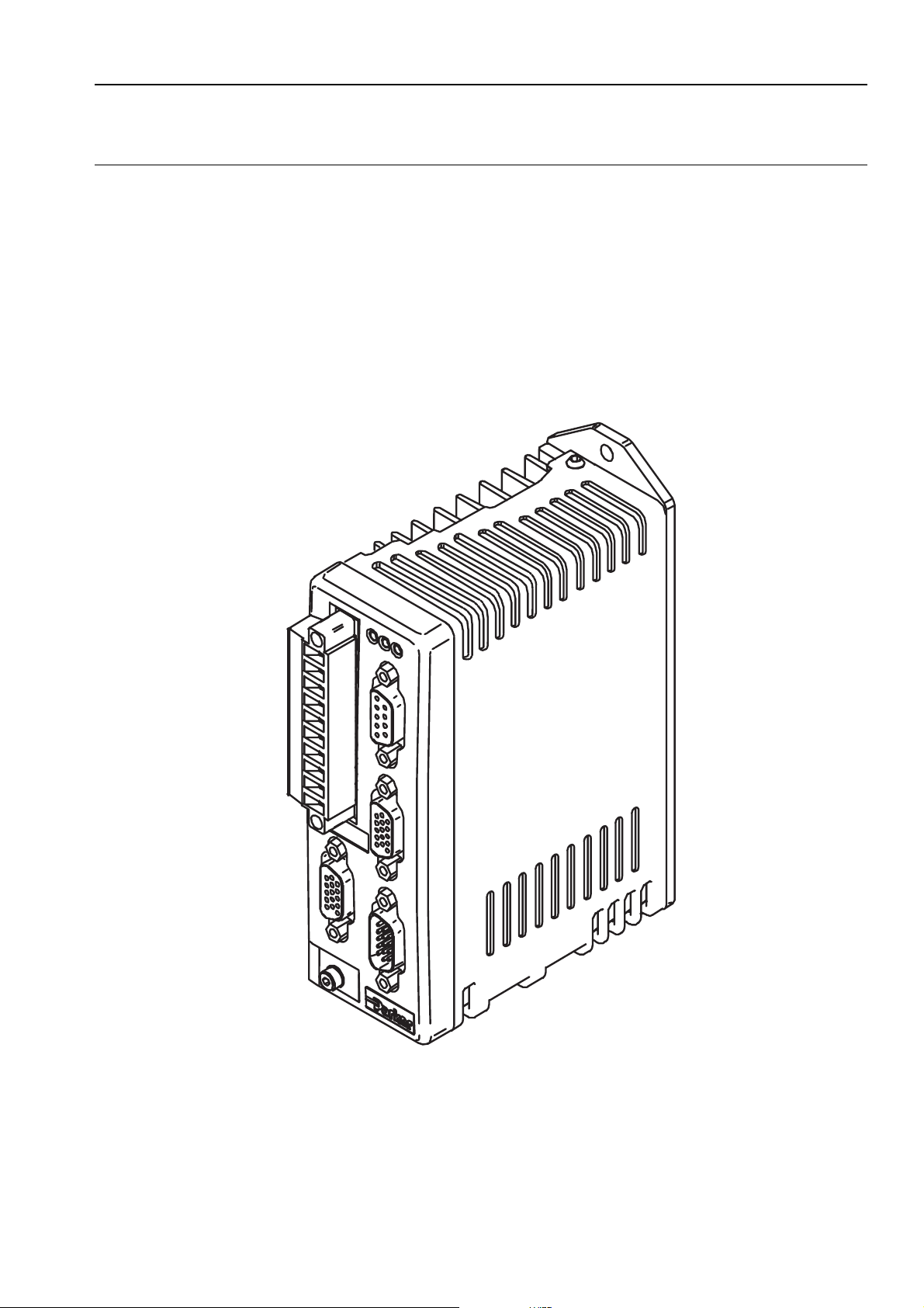
Product Description
Available in two current ratings, these microstepper indexer drives employ an optimised
digital field oriented current loop to provide low speed smoothness coupled with high speed
torque. Advanced digital techniques result in reduced settling time and reduced mid speed
instability when compared with similar competitive drive types.
The common use of EASI-V programming language and similar supply requirements make
this drive ideal for mixed technology applications when used with the ViX digital servo.
Figure 1-1. ViX250/ViX500 Microstepper Indexer Drive

2 VIX IM MICROSTEPPER INDEXER DRIVE USER GUIDE
Product Variants
Digital microstepper indexer drives are available in two current ratings with two interface
options. Table 1-1 lists the possible combinations:
Product Code Description
ViX500IM 5.6A RMS (8A peak) microstepper indexer drive with an
RS232 control interface
ViX250IM 2.8A RMS (4A peak) microstepper indexer drive with an
RS232 control interface
ViX500CM 5.6A RMS (8A peak) microstepper indexer drive with
Canbus/RS485 interface
ViX250CM 2.8A RMS (4A peak) microstepper indexer drive with
Canbus/RS485 interface
Table 1-1. ViX250/ViX500 Microstepper Indexer Drive Options
Note: RS485 serial communication is only included in the CANopen version of the drive.
Product Features
Protection Circuits
Motor short circuits, phase to phase,
phase to ground
Over-voltage trip
Under-voltage trip
Drive/motor Over-temperature
24V reverse supply protection
Function Indicators
Drive Status/Feedback Fault (HV/FB)
Drive Fault (DF)
Comms. Status (CS)
Outputs and Inputs
3 digital outputs
5 digital inputs
1 analogue input

Fit Kits
A fit kit is available for ViXIM drives:
VIX-KIT
Part Number Quantity Description
1650.937.01 1 Information
5004.023 1 Plastic bag
5006.211 1 Product label
0405.811 1 10-way Flange
0405.961 1 9-way D-type
0405.962 2 15-way HD
0405.963 1 15-way HD
0409.530 4 9-way D-type
0313.020 1 H8FE1115NC
4005.218 1 3:1 heatshrink
4216.101 1 Closed P-clip
4216.102 1 Closed P-clip
4216.103 1 Closed P-clip
1. INTRODUCTION 3
sheet
plug strip
plug
D-type plug
D-type socket
cover
ferrite sleeve
19mm diam.
9mm ID
10.7mm ID
12.3mm ID

4 VIX IM MICROSTEPPER INDEXER DRIVE USER GUIDE
Further Information
This user guide contains all the necessary information for the effective use of this drive.
However, to gain a more in-depth understanding of drive applications and motion control,
consider attending one of our world-wide Customer Specific Training Workshops.
Examples of previous courses that have proved to be of benefit include:
Use and programming of the DIN rail H & L series drives
PDFX training
Using the 6K controller
EASI Tools programming
Mechanical product training for ET/ER, XR and HPLA

2. MECHANICAL INSTALLATION 5
2. Mechanical Installation
Installation Requirements
Environment
ViX drives operate in a temperature range of 0° to 40°C with natural convection, or 50°C
Max with forced-air cooling (see Hardware Reference), at normal levels of humidity (5-95%
non-condensing). The drives can tolerate atmospheric pollution degree 2, which means only
dry, non-conductive pollution is acceptable.
Drive Cooling
Cooling of all drive types is by natural convection up to 40°C. To assist cooling, drives
should be installed vertically in an area where there is at least a 50mm (minimum) air gap
above and below the package and a 10mm (minimum) gap either side. Avoid mounting
heat-producing equipment directly below a drive.
Installers must ensure that the air temperature entering the drive or rising up to the drive is
within the ambient temperature restrictions. Under normal use the air temperature leaving
the drive and heatsink may be 25°C above ambient.
In the final installation, check that the ambient temperature specification of 40°C Max
(without forced air cooling) is not exceeded directly below the top-most drives and that any
circulating air flow is not being blocked from reaching the drives. For cabinet cooling
calculations, allow 20W per drive. For DIN rail mounting, see the thermal limitations
statement in Drive Mounting Options.
6 VIX IM MICROSTEPPER INDEXER DRIVE USER GUIDE
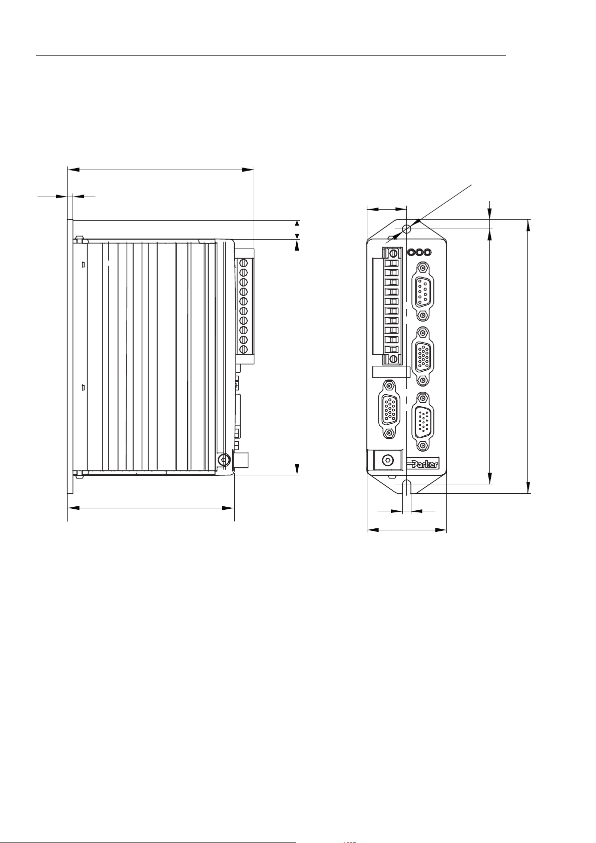
Drive Dimensions
ViX250 and ViX500 drives share the same dimensions, shown in Figure 2-1.
98.5 (with connector)
3
10.1
124.7
21
X1
X2
HVSTFB
X3
X4
X5
5
135
145
4,5
88,1
4,5
42
Figure 2-1. ViX250 & ViX500 Dimensions
2. MECHANICAL INSTALLATION 7
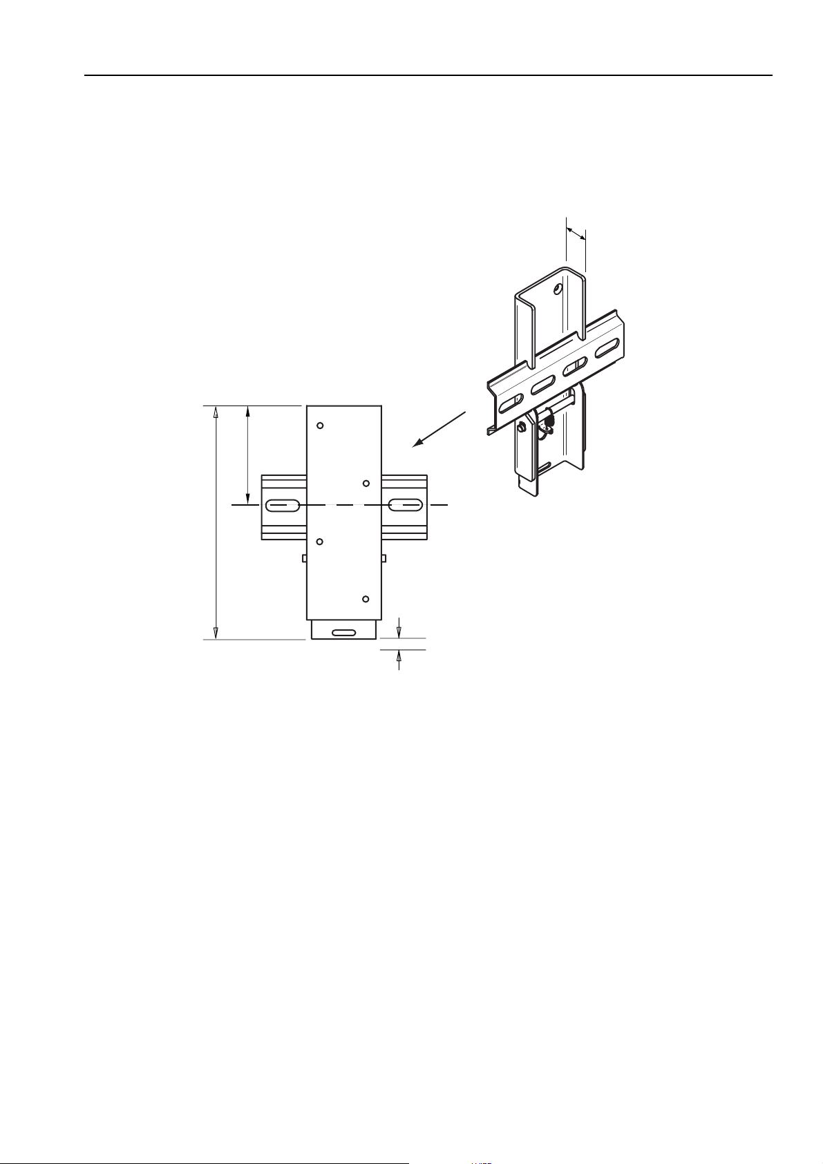
Drive Mounting Options
If you require a DIN-Rail mounting ViX drive use the optional DIN-Rail clip adapter bracket
shown in Figure 2-2.
16mm
57.2mm
Viewed from the back
131.2mm
of the DIN rail
Allow 10mm
for release
Figure 2-2. DIN-Rail Adapter Bracket
Remove the panel mounting plate from the back of the drive and attach the bracket to the
back of the drive using the screws provided. The drive and bracket can now be fixed to a
DIN rail by hooking the top of the bracket over the top of the DIN rail and gently pushing the
drive forward to engage the lower section of the bracket. Remove the bracket by inserting a
flat bladed screwdriver into the release slot to pull down the bottom of the bracket, releasing
it from the DIN rail.

8 VIX IM MICROSTEPPER INDEXER DRIVE USER GUIDE
Motor Mounting Mechanical Considerations
Keep motors securely fixed in position at all times. Do not test a motor/drive combination
without first securing the motor – see the Safety Warning at the front of this user guide.
CAUTION – risk of equipment damage
Do not back drive the motor, that is use the motor in an application that causes
mechanical rotation of the motor shaft in a manner uncontrolled by the drive.
Back driving the motor at high speed may damage the drive.

3. ELECTRICAL INSTALLATION 9
3. Electrical Installation
Installation Safety Requirements
ViX stepper drives meet the requirements of both the European LVD & EMC directives when
installed according to the instructions given within this section. It is recommended the drive
be installed in an enclosure to protect it from atmospheric contaminants and to prevent
operator access while it has power applied. Metal equipment cabinets are ideally suited for
housing the equipment since they can provide operator protection, EMC screening, and can
be fitted with interlocks arranged to remove all hazardous motor and drive power when the
cabinet door is opened. Do not arrange interlocks to open circuit the motor phase
connections while the system is still powered, as this could cause damage to the drive.
Precautions
During installation, take the normal precautions against damage caused by electrostatic
discharges. Wear earth wrist straps. A switch or circuit breaker must be included in the
installation, which must be clearly marked as the disconnecting device and should be within
easy reach of the machine operator.
Cabinet Installation
To produce an EMC and LVD compliant installation we recommend that drives are mounted
within a steel equipment cabinet. This form of enclosure is not essential to achieving EMC
compliance, but does offer the benefits of operator protection and reduces the contamination
of the equipment from industrial processes.
A steel equipment cabinet will screen radiated emissions provided all panels are bonded to a
central earth point. Separate earth circuits are commonly used within equipment cabinets to
minimise the interaction between independent circuits. A circuit switching large currents and
sharing a common earth return with another low level signal circuit could conduct electrical
noise into the low level circuit, thereby possibly interfering with its operation. For this reason
so called ‘dirty earth’ and ‘clean earth’ circuits may be formed within the same cabinet, but all
such circuits will eventually need to be returned to the cabinet’s main star earth point.
Mount the individual drives and EMC filter on a metal earth plane. The earth plane will have
its own individual star point earth which should be hard wired (using an insulated copper
conductor) back to the cabinet’s ‘clean earth’ connection point.
LVD - Low voltage directive
EMC – Electro Magnetic Compatibility directive
10 VIX IM MICROSTEPPER INDEXER DRIVE USER GUIDE
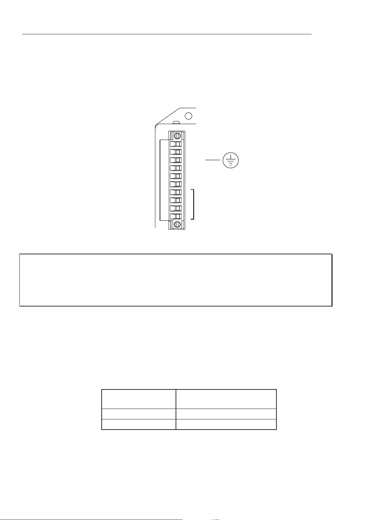
Power Supply Connections
Power drives from a DC supply derived from an isolating transformer or a DC power supply
(See Power Supply Options later in this section).
Note: Pin 10 is at the top of the connector X1 and pin 1 at the bottom.
Power & motor
10-way
connector
X1
10
+HV
9
8
7
6
5
4
3
2
1
-HV
PE
+24V DC
0V (GND 24v DC)
GND
MOTOR
CONNECTIONS
Figure 3-1. X1 Power Connections
WARNING – Possible drive damage
If you use Parker XL Series stepper drives, do not attempt to use any power wiring
harness taken from an XL drive. Although the same mating connector is used for
both an XL and a ViX, the ViX wiring is the reverse of the XL and the wrong wiring
connection will damage the drive.
Mating connector type is: Wieland 8213B/10 F OB, Part number 25.323.4053.0 (Parker part
number 0405.811).
Supply Requirements
Power the ViX drives from DC supplies as specified below:
Volts
Drive Type DC Supply Voltage
between +HV and -HV
ViX500 48V to 80V (recommended)
ViX250 24V to 80V
Table 3-1. Drive Supply Voltages

3. ELECTRICAL INSTALLATION 11
WARNING
The drive HV supply input is not reverse polarity protected.
Reverse polarity connections will damage the drive.
Current and Capacitance
A supply must have a minimum amount of capacitance to support a drive at peak power
draw.
Drive Type DC Supply Current Supply Capacitance
ViX500 5.6A RMS
ViX250 2.8A RMS
Table 3-2. Drive Supply Currents
6600µF
3300µF
+24V Requirements
Both drive types require a +24V controller and logic supply. The supply may also be
required for an encoder and a Fieldbus Expansion Module (FEM).
Absolute voltage range 20 to 27V
Nominal drive current 250mA (excluding encoder, & FEM)
Encoder supply loading 150mA (if required)
FEM current 50mA
Safety Earth Requirements
Earth the drive using the earth pin on X1 (pin 8).
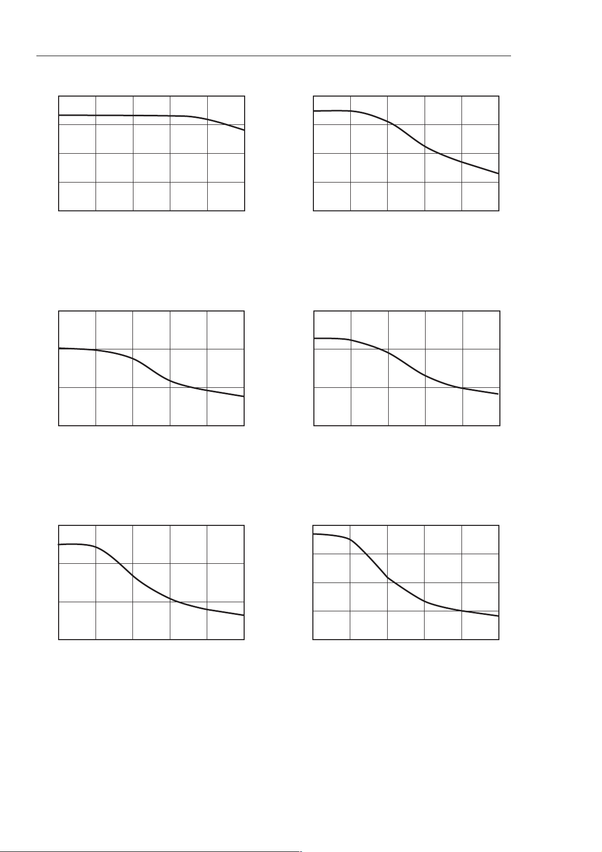
Power Supply Options
A set of torque curves (Figure 3-2) for various motor/drive combinations can be used for
calculating an applications likely power requirements.
Higher torque/current requirements will need to use the ViX500 drive and a high current
linear supply, such as the PL1100. Further power supply information is given in Appendix A.
12 VIX IM MICROSTEPPER INDEXER DRIVE USER GUIDE
N
N
N
mNm
0.4
0.3
0.2
0.1
0
0
ViX250 with SY561
10 20 30 40 50
0.8
0.6
0.4
0.2
0
0
ViX250 with SY562
10 20 30 40 50
Speed, revs/sec Speed, revs/sec
mNm
1.5
1.0
ViX500 with SY563
1.5
1.0
ViX250 with SY871
0.5
0
0
10 20 30 40
50
0.5
0
0
10 20 30 40 50
Speed, revs/sec Speed, revs/sec
mNm
3.0
2.0
1.0
0
0
ViX500 with SY872
10 20 30 40 50
4.0
3.0
2.0
1.0
0
0
ViX500 with SY873
10 20 30 40 50
Speed, revs/sec Speed, revs/sec
Figure 3-2. Stepper Drive Torque/Speed Data

3. ELECTRICAL INSTALLATION 13
XL-PSU Power Supply
The XL-PSU is a 250W, power factor corrected, switched mode power supply. Designed for
direct operation from world wide single phase AC input voltages, the supply is capable of
powering up to two ViX250 drives (see note 1) without the need for an EMC mains input filter
(see note 2). The use of the XL-PSU offers the following benefits:
• Auto-adapts to supplies between 95 and 264V AC
• No external EMC filter required
• Compact size
• Built-in +24V DC supply
Note 1: Check the application’s power requirements from the torque/speed curve of the
motor used.
Note 2: For drives with up to 30 metre motor leads.
For full installation instructions see the XL Power Supply leaflet 1600.300.XX.
14 VIX IM MICROSTEPPER INDEXER DRIVE USER GUIDE
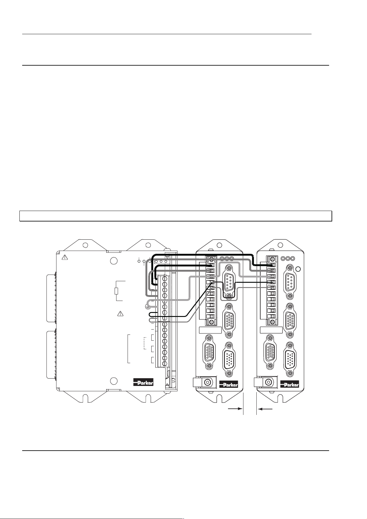
XL-PSU Supply/Drive Connections
When used to supply up to two drives the power supply can be wired as shown in Figure 3-3.
X1
10
1
ST
HV FB
X3
X4
10 mm
Mininum spacing
between drives & PSU
1
+DC (80V)
-DC
EXT. BRAKING RES.
+24V
GND
10
If the supply is positioned
this side of the drive
avoid blocking access to
D-type X3
P1
P2 mating socket
X2
MAINS
N
INPUT
X5
L
110V-230V~
50/60 Hz
250VA
P2
XL
Power
Supply
Unit
HV STATUS
BRAKING RES.
24V STATUS
Figure 3-3. XL Power Supply and Drive Connections
LN
EARTH (GND.)
The XL_PSU must
be securely earthed
Note: A kit of five connecting links is available, called ‘XL-connect’. You will need one kit for
every drive.

3. ELECTRICAL INSTALLATION 15
XL-PSU Mounting Information
Mount the supply vertically, near the drives it will supply. Both the top 4.5mm diameter fixing
hole and the bottom two 4.5mm width fixing slots should be used.
Allow a minimum free space of 50mm both below and above its case and 10mm free space
on both sides.
Do not mount the supply above or close to other products that generate a significant amount
of heat by radiation or convection.
16 VIX IM MICROSTEPPER INDEXER DRIVE USER GUIDE
PL1100 Power Supply
General Description
The PL1100 is a linear power supply with a rated output of 1120W (80V/14A) for use with
ViX and XL series drives. The supply requires a suitably rated transformer supplying 50V
AC RMS for the HV and 20V AC RMS for the +24V DC. The use of the PL1100 offers the
following benefits:
• Provides 80V HV and +24V DC output
• Single or three phase operation
• Built-in power dump switch
• Integral fusing
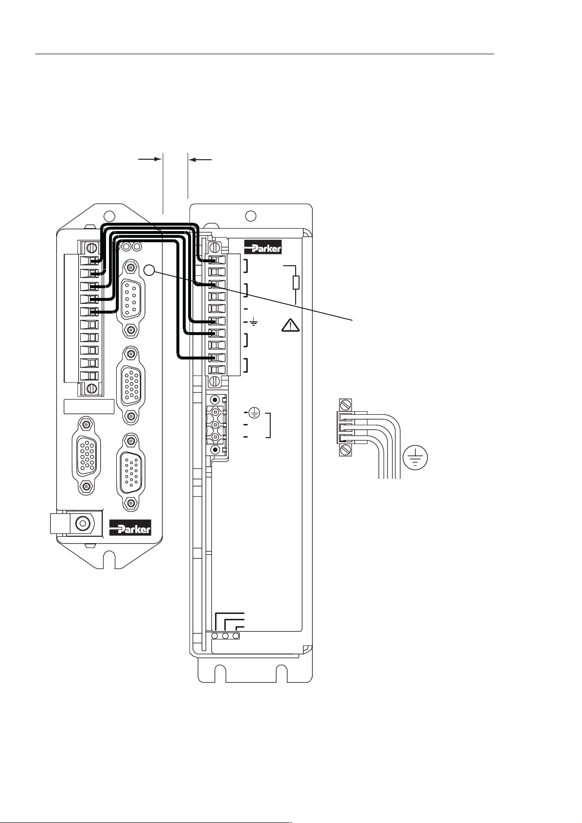
Figure 3-4 shows the PL1100 output wiring for two ViX drives. This illustrates how to route
the main HV supply separately to each drive. The lower current requirements of the +24V
logic/brake supply can allow the wiring to be linked between drives.
For full installation instructions see the PL1100 Power Supply leaflet 1600.323.XX.
ST
CAUTION
Risk of electric shock.
High voltage remains on terminals
after power is removed.
Allow 5 minutes for capacitors
to discharge.
PL1100
Power Supply
55V
AC IN
1/3 PH.
HV
REGEN
X1
MOTOR HV OUT
MOTOR 0V.
EXT. BRAKING RES.
PE
+24V DC OUT
20V AC IN
20V AC IN
LINK
FOR
SINGLE
PHASE
X2
+24V
0V
L3
L2
L1
X1
X2
ST
HV FB
10
X3
X4
1
X5
X1
10
X2
HV FB
X3
X4
1
X5
10 mm MIN
Figure 3-4. PL1100 Power Supply and Drive Connections

3. ELECTRICAL INSTALLATION 17
EMC Installation
These EMC installation recommendations are based on the expertise acquired during the
development of compliant applications, which Parker believes are typical of the way, a drive
or drives may be used. Provided you have no special installation requirements or untypical
operating environment requirements, ViX drives will conform to current EMC Directives, as
defined at the front of this user guide.
General Requirements
ViX mounted drives, unless used with an XL-PSU, will require an EMC supply filter to meet
EMC installation compliance requirements. Mount the drive on a conductive panel which is
shared with the EMC filters. If the panel has a paint finish, it will be necessary to remove the
paint in certain areas to ensure filters and drive make a good large-area metal to metal
contact between filter case and panel.
Mount filters close to the drive and keep the supply wiring as short as practical. Attempt to
layout the wiring in a way that minimises cross coupling between filtered and non-filtered
conductors. This means avoiding running wires from the output of a filter close to those
connected to its input. Where you wish to minimise the cross coupling between wires avoid
running them side-by-side one another, if they must cross, cross them at 90° to each other.
Keep wiring supported and close to cabinet metalwork.
Recommended EMC filter types are CORCOM 6FC10 for loads up to 6A and 3VK1 for the
+24V supply up to 3A. Multi-axis systems may require higher current rated filters.
+24V Supply Connections
ViX drives not using an XL-PSU will require a logic supply of +24V DC at 250mA (nominal)
per drive. The +24V powers the controller and I/O circuits. Keeping the +24V independent
of the drive’s internal high voltage bus supply allows the option of keeping the I/O and
controller active when no main supply is present.
Connect the +24V supply to X1 pin7 and the return to X1 pin6, the total wire length, from
supply to drive, must not exceed 10m.
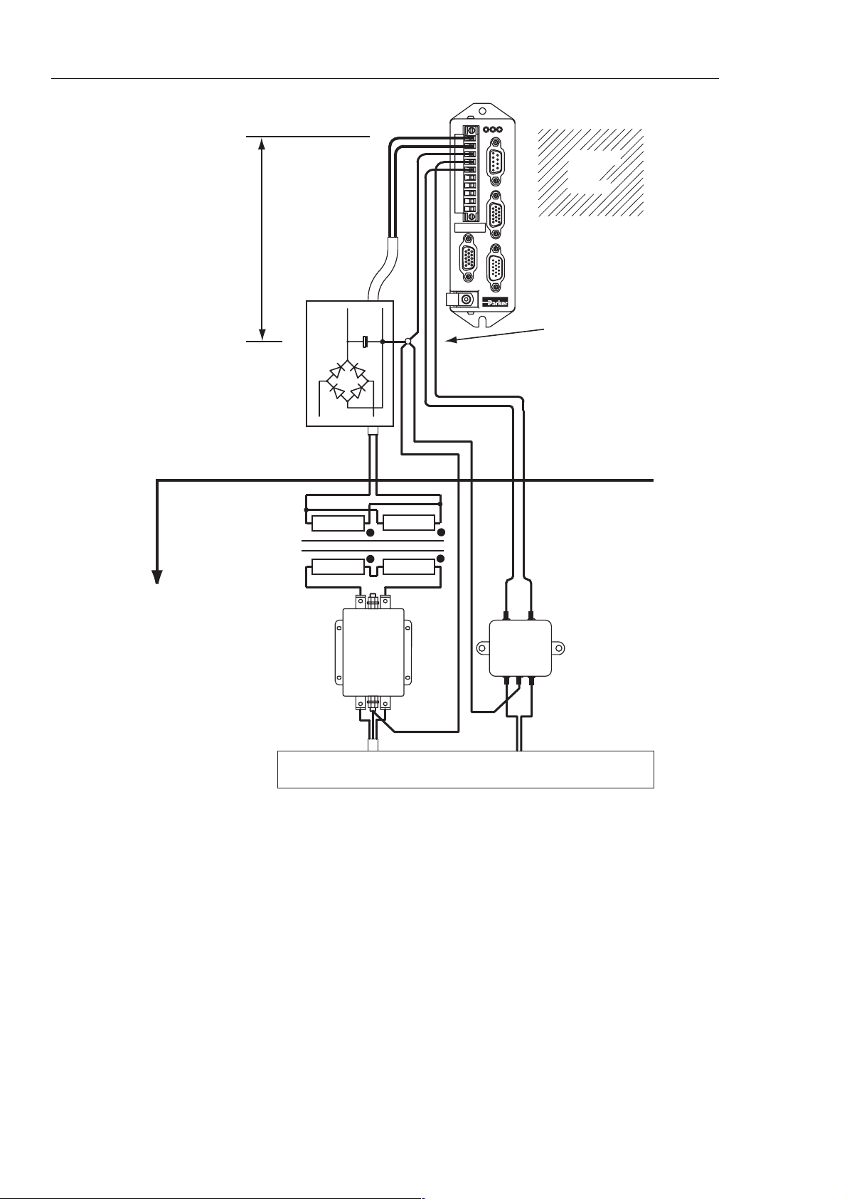
Connect the +24V supply 0V line to system earth (0V) at some convenient point before the
EMC filter input, as shown in the recommended EMC layout diagram, Figure 3-5.
The 24V supply to each drive should be fitted with a time-delay fuse, rated at 3A. Note: The
+24V supply used must meet the voltage requirement specification of +24V DC +10% -15%,
ripple <1V p-p.
18 VIX IM MICROSTEPPER INDEXER DRIVE USER GUIDE
ST
HV FB
X1
10
X3
Lead length
restriction
(less than 1 metre)
DC Supply
X4
1
X2
X5
CABINET
BACK
PLANE
Star earth point
to the metal
backplane
Located in
the base of
the cabinet
Transformer
AC Supply
CORCOM
Figure 3-5. ViX EMC Installation
(load)
Output
6FC10
(line)
Input
Power wiring conduit
LOAD
3VK1
LINE
+-
DC 24V Supply

3. ELECTRICAL INSTALLATION 19
Motor Connections to the Drive
The recommended wire size for ViX250IM/500IM motor cables, of length less than 20m, is
1mm2. For motor cable lengths greater than 20m (up to a maximum of 50m) use a wire size
of 2.5mm
34805), the green wire being used to provide an earth return to the drive. Termination at the
motor must be made using a 360° bond to the motor body, and this may be achieved by
using a suitable clamp. Many stepper motors are designed to accommodate an appropriate
terminal gland which can be used for this purpose.
At the drive end of the cable, a 360° connection to the screen should be made using the
P-clip provided beneath the motor connector. The P-clip needs to be firmly clamped to the
copper braid. If the connection appears loose, fold the braid back on itself to increase the
amount of braid under the clip and re-tighten.
Custom cables will require the cable insulation to be removed to expose the braided screen.
If you are using a motor cable with 2.5mm
9mm to accommodate the increased cable diameter. A ferrite absorber, with a specification
matching that of the Chomerics H8FE-1115-NC, is also required to be positioned on the
motor cable using heat shrink sleeving or cable ties. The position of the absorber should be
within 150mm of the drive. Always secure the cable using the P-clip, as shown. Do not rely
upon the connector alone holding the motor cable in place. Avoid stress on the X1
connector by hanging cables, as this may lead to connector over-heating.
2
. Use a cable containing five conductors plus the braided screen (such as Lapp
2
conductors the size of the P-clip will need to be
Make a 360° connection to the screen using one of the stainless steel or brass P-clips
supplied within the fit kit.
Size Parker part number
9mm ID 4216.101
10.7mm ID 4216.102
12.3mm ID 4216.103
Table 3-3. P Clip sizes
Three different size ‘P’ clips allow the use of a variety of motor power cables from different
manufactures.
There must be no break in the 360° coverage that the screen provides around the cable
conductors. If a connector must be used it should retain the 360° coverage, possibly by the
use of an additional metallic casing where it passes through the bulkhead of the enclosure.
The cable screen must not be bonded to the cabinet at the point of entry. Its function is to
return high-frequency chopping current back to the drive. This may require mounting the
connector on a sub-panel insulated from the main cabinet, or using a connector having an
internal screen which is insulated from the connector housing. Within the cabinet itself, all
the motor cables should lie in the same trunking as far as possible. They must be kept
separate from any low-level control signal cables. This applies particularly where the control
cables are unscreened and run close to the drive.

20 VIX IM MICROSTEPPER INDEXER DRIVE USER GUIDE
Note that the motor cable routing within the equipment cabinet should be kept at least
300mm away from I/O cables carrying control signals.
All motor connections must be made using a high quality braided-screen cable. Cables
using a metallised plastic bandage for an earth screen are unsuitable and in fact provide
very little screening. Care must be taken when terminating the cable screen, the screen
itself is comparatively fragile; bending it round a tight radius can seriously affect the
screening performance. The selected cable must have a temperature rating which is
adequate for the expected operating temperature of the motor case.
Motor Cables
Motor cables may be ordered using the part numbers listed in Table 3-4.
Product code/Part
number
STC20-0300 3
STC20-0500 5
STC20-1500 15
Table 3-4. Motor Cables
Length (metres)
Motor Phase Contactors
We recommend that motor phase contactors are not used within the motor power cables. As
an alternative, make use of the drive’s power stage ‘enable’ control signal.
Ferrite absorber specifications
The absorbers described in these installation instructions use a low-grade ferrite material
that has high losses at radio frequencies. They therefore act like a high impedance in this
waveband. Produced by Parker Chomerics, the recommended component is suitable for use
with cable having an outside diameter up to 10mm. The specification is as follows:
Chomerics part number H8FE-1115-NC (Parker part number 0313.020)
Outside diameter 17.5mm
Inside diameter 10.7mm
Length 28.5mm
Impedance at 25MHz 80 ohm
Impedance at 100MHz 120ohm
Curie temperature 130°C (the device should not be operated near this temperature)

3. ELECTRICAL INSTALLATION 21
Motor Selection
Usually optimum performance will be obtained when the current rating of the motor is
between 1 and 1.5 times the drive rating. Drives can be de-rated to accommodate motors
with lower current ratings (using variable MC within the MOTOR command), however the
high speed torque will be reduced.
Do not use a drive setting which gives an output current greater than the motor rating.
With 4 lead motors the bipolar rating is quoted and this should match the criteria stated
above.
With 8 lead motors the bipolar rating of the motor, which is normally quoted, refers to a
parallel winding connection. With the windings connected in series the current rating of the
motor connection will be 50% that of the bipolar rating, and the motor will give improved lowspeed torque, but reduced high-speed torque.
The ViX250IM/ViX500IM will drive motors having an inductance as low as 0.5mH and as
high as 20mH, but the recommended motor inductance range is between 0.8mH and 10mH.
Performance of the ViX250/ViX500IM is optimised for the following motor types, listed in
Table 3-5.
Motor Type Motor Rated
Current in
Amps*
SY561 4.2 1.0
SY562 4.2 2.6
SY563 6.5 1.2
SY871 4.2 1.6
SY872 6.5 1.5
SY873 8.4 1.7
SY1072 8.0 2.4
*(parallel connection)
Table 3-5. SY Optimum Motor Types
Motor Voltage Ratings
Motors with a withstand voltage rating from phase to earth of 1000V AC should be used. An
insulation withstand rating of 500V AC is acceptable if an isolating transformer with earthed
screen is used to power the system, and 0V input is earthed, as specified.
Motor
Inductance
in mH per
phase*
ViX500IM ViX250IM
✔
✔✔
✔
✔✔
✔
✔
✔
22 VIX IM MICROSTEPPER INDEXER DRIVE USER GUIDE
Large Motors
The largest recommended motor size is a 34-frame 3-stack. Please contact Parker if
you wish to use a larger frame motor.
Motor Connections at the Motor
Motor connections should be made directly between the drive and motor, the use of any
switching devices, such as contactors is not recommended.
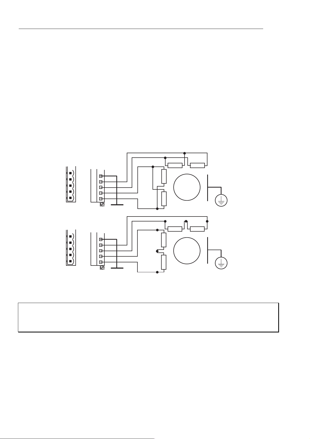
In the majority of applications the drive will be used with an eight lead motor with the
windings connected in parallel or series, as shown in Figure 3-6. Motor connections will
need to be determined from the motors data sheet or Appendix B. These are normally
identified by wire colour or terminal markings, depending upon the make of the motor.
+
-
+
MOTOR CONNECTOR
X1
5
4
3
2
1
Gnd
A+
AB+
B-
Motor case
-
+
-
+
-
MOTOR
PARALLEL
CONNECTIONS
SAFETY
EARTH
MOTOR CONNECTOR
X1
5
4
3
2
1
Gnd
A+
AB+
B-
Motor case
-
+
-
+
-
SERIES
CONNECTIONS
MOTOR
SAFETY
EARTH
+
-
+
Figure 3-6. 8 Lead Motor Connection Options
WARNING - High Temperature
The motor case temperature may exceed 70°C and should be guarded from operator
contact.
Motor Safety Earth/Ground Connection
It is recommended that the motor is independently bonded to a local safety earth point. The
safety earth lead should be at least 2.5mm
2
in area.
3. ELECTRICAL INSTALLATION 23
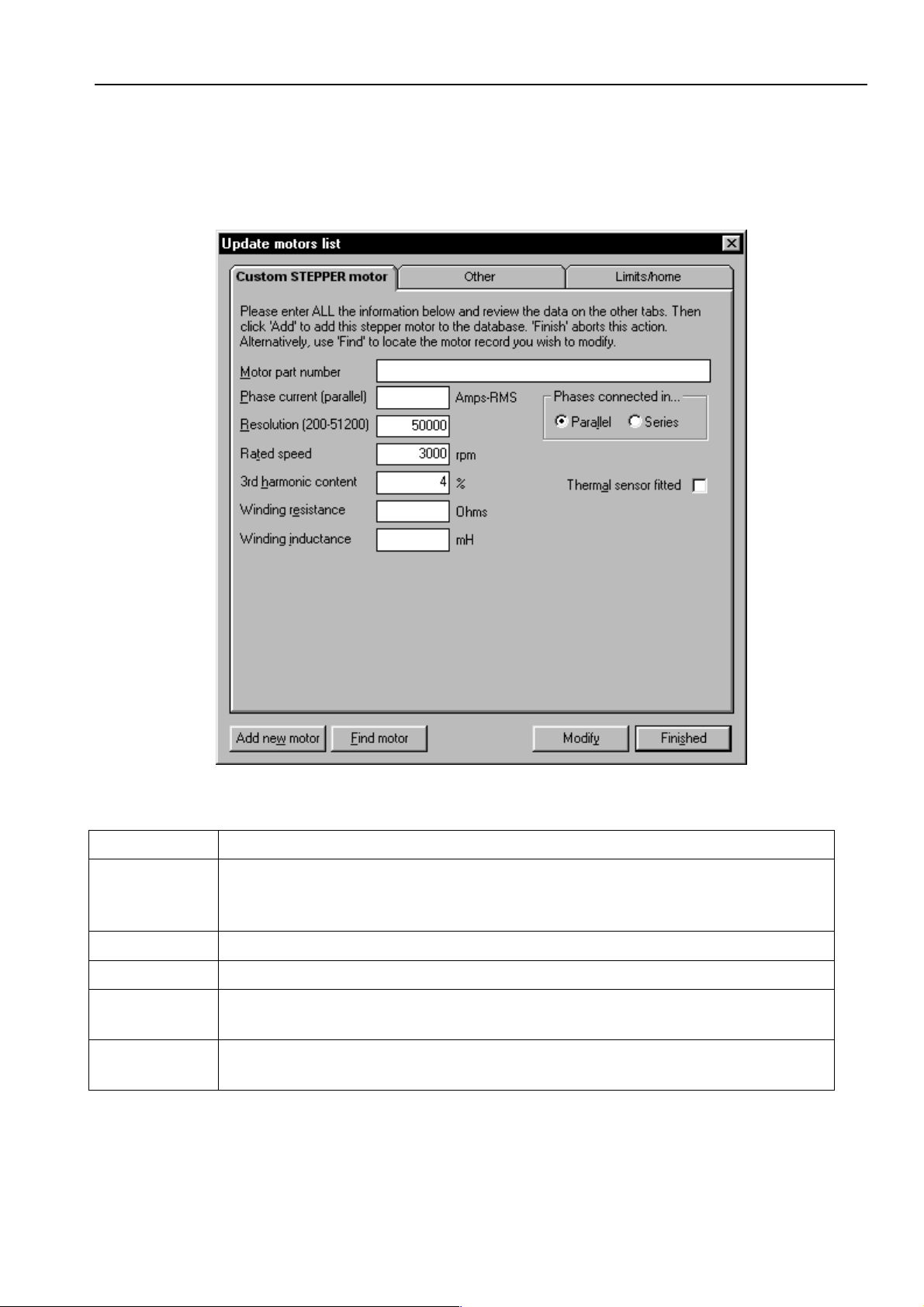
Custom Motor Set Up
Within screen 2 of Guided stepper initialisation, clicking upon the Setup custom button will
open the window shown in Figure 3-7.
Figure 3-7. EASI-V Custom Motor Configuration Window
Motor the general name/number for the motor.
Phase
current
(parallel)
Resolution number of steps per revolution
Rated speed shaft speed in rpm for a rotary stepper.
Winding
resistance
Winding
inductance
continuous current rating of the motor in Amps RMS.
resistance of a single phase winding measured line-to-line in Ohms.
inductance of a single phase winding measured line-to-line in mH.
 Loading...