

Page 1

aerospace
climate control
electromechanical
filtration
fluid & gas handling
hydraulics
pneumatics
process control
sealing & shielding
PSG Combination
Moisture & Liquid Indicator
Catalog B-1, October 2007
Page 2

Page 2 / Catalog B-1, PSG Moisture/Liquid Indicator
Parker PSG Moisture & Liquid Indicator
The Parker PSG Moisture and Liquid
Indicator combines the two functions
of moisture and liquid indication into
a single economical product. It takes
the guess work out of servicing refrigeration and air conditioning equipment.
The PSG assists the technician in determining the state of the circulating refrigerant at a particular location and if a safe
moisture level exists in the system. Excessive moisture in refrigerant systems
can cause unwanted chemistries such as
hydrolysis of lubricants and other materials, corrosion of metals, copper plating, ice formation at the metering device
and a chemical change in the motor insulation of a hermetic compressor.
8 Outstanding Benefits
One Indicator For All Refrigerants —
provides a true moisture indication for
Refrigerant 12, 134a, 22, 404A, 407C, 410A,
502 or 507.
Reliable And Accurately Calibrated Color
Change Points — calibration in parts per
million of moisture for each refrigerant. 3%
relative humidity indicator for CFC, HCFC,
and HFC, including R410A.
Replaceable Indicator Element — the color
indicator paper can be changed without removing the PSG from the line.
Indicator Protected From Discoloration
And Dirt — by a filter pad and screen. This
prevents washing of the indicator by the
refrigerant and protects it from system
contamination and turbulence.
Color Changes Are Easily Distinguished
And Reversible —
widely between the wet and dry condition,
there is no possibility of confusion. Colors reverse as often as moisture concentration in
the system changes.
indicator colors differ so
Plastic Cap — is supplied with PSG to keep
the glass free from dust, dirt and grease.
How It’s Made
The plated steel and copper ttings are
copper brazed to the heavily copper
plated steel body. A glass disc is inserted
in the body and heated, just to the melting point, under carefully controlled
conditions. This fuses the glass to the
body in a permanent leak-free joint. The
indicator paper (retained in a small brass
ferrule) is inserted from the back and
held in place with a slotted cylinder. The
slotted cylinder and indicator assembly
is mounted on a post that screws into
the bottom of the body, and seals with a
knife-edge joint. This overall construction is highly effective in preventing refrigerant leakage. The unit is painted to
protect it from corrosion.
Paper indicator elements are made in
the Parker laboratory under the strictest
quality control procedures. The indicator is tested for proper color change
ability in the laboratory and twice more
during assembly.
How It Works
The indicator is a porous lter paper
impregnated with a chemical salt that is
sensitive to moisture. The salt changes
color according to the moisture content
(relative saturation) in the refrigerant.
A dark blue color indicates the refrigerant is DRY and pink indicates a WET
condition. The indicator is formulated
so that it changes color at the moisture
levels generally accepted as the safe operating range.
Figure 1
The PSG calibration information in
Tables 1 and 2 is based on detailed
experimental data for Refrigerants 12,
22, 134a, 404A, 407C, 410A, 502 and
507. The PSG change points occur at
similar or lower moisture levels than
competing models promoted to have 3%
relative humidity indication.
For Air — Tests on air show that the PSG
changes color in the range of 0.5% to 2.0%
R.H. In ordinary air lines this means that the
PSG will change color at dew points in the
range of minus 40°F to -60°F (-40°C to -51°C).
Brazing
PSGs with 1/4” through 1-1/8” ODF
Solder connections are constructed with
long ttings made from either heavily
copper plated steel or copper. Both t-
ting types are suitable for soldering or
brazing using any of the common alloys,
such as silver solder, soft solder, StaBrite, or Sil-Fos or PhosCopper. PSGs
do not require disassembly in the eld
for brazing because the extended ttings
reduce the possibility of damaging the
moisture indicator element when the
PSG is brazed into the system. To prevent damaging the PSG, ensure ample
heat is supplied to the ttings and point
the torch tip away from the PSG body.
Proper brazing technique ensures proper
capillary action of the alloy.
The ODF Solder connections on the
PSG are clean when shipped. Polishing
the inside of the ttings before brazing is unnecessary, and could be harm-
ful on the copper plated steel ttings if
an excessive amount of copper plating
Large Full View Sight Glass — extra large
crystal clear sight glass for viewing the refrigerant. Bubbles indicate a shortage of
refrigerant or a restriction in the liquid line.
Disassembly For Installation Is Unnecessary
— with extended fittings on small size solder
models. PSGs are easy to braze.
Parker Hannifin Corporation, Climate and Industrial Controls Group, Cleveland, OH
Page 3

Table 1
Screen
Slotted Cylinder
Indicator
Paper
Filter
Pad
Brass
Ferrule
Moisture Content - PPM/°F
Catalog B-1, PSG Moisture/Liquid Indicator / Page 3
PSG
SHOWS
Blue - DRY
Intermediate Color - CAUTION
Pink - WET
Table 2
REFRIGERANT12REFRIGERANT22REFRIGERANT
75°F 100°F 75°F 100°F 75°F 100°F 75°F 100°F 75°F 100°F 75°F 75°F
Below5Below10Below30Below45Below50Below80Below10Below20Below15Below
5-15 10-30 30-90 45-130 50-200 80-225 10-45 20-65 15-90 30-140 120-280 75-150
Above15Above30Above90Above
130
Above
200
134a
Moisture Content - PPM/°C
REFRIGERANT12REFRIGERANT22REFRIGERANT
PSG
SHOWS
24°C 38°C 24°C 38°C 24°C 38°C 24°C 38°C 24°C 38°C 24°C 24°C
Blue - DRY
Intermediate Color - CAUTION
Pink - WET
NOTE: Change or add Parker Filter-Drier when paper turns from blue to intermediate color.
is removed. PSGs with 1/4” through
1-1/8” ODF Solder ttings stated in
this publication are with copper plated
steel ttings.
Below5Below10Below30Below45Below50Below80Below10Below20Below15Below
5-15 10-30 30-90 45-130 50-200 80-225 10-45 20-65 15-90 30-140 120-280 75-150
Above15Above30Above90Above
130
replacement of a drier on existing installations. In some cases the PSG will
change in as short a time as 15 minutes.
However, it is recommended that the
equipment operate for about 12 hours
The larger PSGs with 1-3/8”, 1-5/8”, and
2-1/8” ODF Solder connections utilize
copper connections and require removal
of the cartridge from the brass saddle
adaptor before brazing. The cartridge is
shipped hand tight for easy removal.
The PSG may be installed anywhere in
the the liquid line, but preferably after
the Parker Filter-Drier and ahead of the
metering device.
to allow the moisture in the system and
the PSG color to come to complete equi-
librium. The action of the indicator ele-
ment is completely reversible and will
change color as often as the moisture
content of the system varies.
The drying of the system should be
continued until the indicating element
changes from the intermediate color to
blue. The actual moisture content of the
refrigerant will be in accordance with
the above table.
Above
200
134a
Application
The indicator element of the PSG prior
to installation will be pink, indicating
a wet condition. This is a normal situation since the air in contact with the
element is above 0.5% Relative Humidity. This does not affect the operation or
calibration of the PSG. As soon as it is
installed in a system, the indicator element will begin to change according to
the moisture content of the refrigerant.
Some change may take place rapidly
at the start-up of a new system or after
For best results with the nickel plated
SAE are ttings that are used on PSGs,
lubricate the are surface and the back
Figure 2
REFRIGERANT
502
LIQUID LINE TEMPERATURE
Above
Above45Above65Above90Above
225
REFRIGERANT
502
LIQUID LINE TEMPERATURE
Above
Above45Above65Above90Above
225
REFRIGERANT
404A & 507
REFRIGERANT
404A & 507
30
140
30
140
REFRIGERANT
407C
Below
120
Above
280
REFRIGERANT
407C
Below
120
Above
280
REFRIGERANT
410A
Below
75
Above
150
REFRIGERANT
410A
Below
75
Above
150
of the are nut with refrigerant grade
oil during assembly. This is particularly necessary to avoid leaks if the PSG
is being assembled to another plated
steel are tting, such as the Parker
Filter-Drier.
Service Pointers
Replacement Indicator Paper — Parker
kit K-PSG-1 consisting of a slotted cylinder
and indicator paper assembly is available
for replacing the indicator in the fused glass
style Parker PSGs (1/4” thru 1-1/8” sizes). Replacement is through the bottom (see Figure
1). If the indicator becomes damaged, it is
generally recommended that the entire PSG
be replaced. However, the parts kit can be
used in situations where it is difficult to remove the PSG.
Liquid Water — On occasion it is possible for large quantities of water to enter a
Parker Hannifin Corporation, Climate and Industrial Controls Group, Cleveland, OH
Page 4
Page 4 / Catalog B-1, PSG Moisture/Liquid Indicator
refrigeration system. An example would be a
broken tube in a water cooled condenser. If
this happens and free water comes in contact with the indicator element, the element
will be damaged.
All moisture indicating elements use a chemical salt (see “How It Works”). These salts
must be soluble in water in order to change
color. If excessive water is present, then
the salts will dissolve, causing permanent
damage to the indicator. The indicator paper
may remain pink or turn white.
Hermetic Motor Burnouts — After a hermet-
ic motor burnout, install a Parker Filter-Drier
to remove the acid and sludge contamination. When the system has operated for 48
hours, replace the Parker Filter-Drier and
install a PSG.
Since the acid formed by the burnout may
damage the indicator element of the PSG,
it is preferable to install it after most of the
contaminants have been removed.
Excess Oil — When a system is circulating
an excessive amount of oil, the PSG indicator
paper may become saturated. This causes
the indicator to appear brown or translucent and lose its ability to change color, but
does not permanently damage the PSG. Let
the PSG remain in the system. The circulating refrigerant will remove the excess oil,
and the indicator element will return to its
proper color.
Leak Detectors — Certain dye type liquid
leak detectors may interfere with the color
change of the indicator paper. If desired,
many of these leak detectors can be removed
by installing a Parker SLD Series Filter-Drier
in the system. The PSG can then be installed
on the system without risk of damaging the
indicator paper.
Alcohol — Do NOT install a PSG in a system
that contains methyl alcohol or similar liquid
dehydrating agents. Remove the alcohol by
using a Parker Filter-Drier, and then install
the PSG. Otherwise the alcohol will damage
the PSG color indicator.
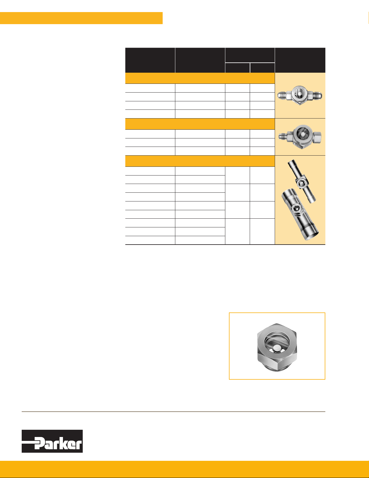
Table 3
Specifications
Connection
Sizes
(Inches)
1/4 PSG-2 2.87 72.9
3/8 PSG-3 3.37 85.6
1/2 PSG-4 3.82 97.0
5/8 PSG-5 4.12 105.0
1/4 PSG-2MF 2.56 65.0
3/8 PSG-3MF 2.97 75.4
1/2 PSG-4MF 3.44 87.4
1/4 PSG-2S
3/8 PSG-3S
1/2 PSG-4S
5/8 PSG-5S
7/8 PSG-7S
1-1/8 PSG-9S
1-3/8 PSG-11S
2-1/8 PSG-17S
Most solder connections can be used as male fittings as well as female fittings. The 1/4” ODF is 3/8” ODM, the 3/8” ODF
is 1/2” ODM, the 1/2” ODF is 5/8” ODM and the 5/8” ODF is 3/4” ODM. Models with female flare connections are supplied
with a copper gasket in the fitting.
Overall width is: 1.31” (33.3 mm) for 1/4” and 3/8” sizes, 1.58” (40.1 mm) for 1/2” and 5/8” sizes, and 1.38” (35.1 mm) for
7/8” and 1-1/8” sizes. Shipping weight is: 7 oz. (.20 kg) for 1/4” and 3/8” sizes, 10 oz. (.28 kg) for 1/2” and 5/8” sizes, 15 oz.
(.43 kg) for 7/8” and 1-1/8” sizes and 1.5 Ibs. (.68 kg) for the PSG-11S, 13S, and 17S series.
UL and ULc Listed - Guide - SEYW - File No. SA-3182. Maximum Rated Pressure is 650 psig (44.8 bar).
Type
No.
Male Flare
Female X Male Flare
ODF Solder
Removable Cartridge
Types PSG-11S, 13S and 17S have copper connections and feature a removable cartridge containing the moisture
indicating element. The cartridge has a
knife edge joint and is available as a
separate unit for eld replacement purposes if necessary. It is designated as
PSG-10TS and ts all three sizes.
Overall
Length
Inches mm
4.63 118.0
4.88 124.0
6.32 161.0
8.00 203.01-5/8 PSG-13S
PSG-10TS
PSG
Parker Hannifin Corporation
Climate and Industrial Controls Group
2445 South 25th Avenue • Broadview, IL 60155-3891 USA
phone 800 742 2681 • fax 800 241 2872
www.parker.com/coolparts
102007 / Catalog B-1
 Loading...