

Page 1

Page 2
User Information
Warning!
ACR Series products are used to control electrical and mechanical
components of motion control systems. You should test your motion system
for safety under all potential conditions. Failure to do so can result in damage
to equipment and/or serious injury to personnel.
ACR Series products and the information in this user guide are the proprietary property of Parker
Hannifin Corporation or its licensers, and may not be copied, disclosed, or used for any purpose
not expressly authorized by the owner thereof.
Since Parker Hannifin constantly strives to improve all of its products, we reserve the right to
change this user guide and software and hardware mentioned therein at any time without notice.
In no event will the provider of the equipment be liable for any incidental, consequential, or
special damages of any kind or nature whatsoever, including but not limited to lost profits arising
from or in any way connected with the use of the equipment or this user guide.
© 2004 Parker Hannifin Corporation
All Rights Reserved
Technical Assistance:
North America and Asia
Parker Hannifin
5500 Business Park Drive
Rohnert Park, CA 94928
Telephone: (800) 358-9070 or (707) 584-7558
Fax: (707) 584-3793
E-mail: cmr_help@parker.com
Internet: www.parkermotion.com
Contact your local automation technology center (ATC) or distributor, or ...
Germany, Austria, Switzerland
Parker Hannifin
Postfach: 77607-1720
Robert-Bosch-Str. 22
D-77656 Offenburg
Telephone: +49 (0) 781 509-0
Fax: +49 (0) 781 509-176
Europe (non-German speaking)
Parker Hannifin
5500 Business Park Drive
Rohnert Park, CA 94928
Telephone: (800) 358-9070 or (707) 584-7558
Fax: (707) 584-3793
E-mail: emn_support@parker.com
Internet: www.parkermotion.com
– ii –
Italy
Parker Hannifin
20092 Cinisello Balsamo
Milan, Italy via Gounod, 1
Telephone: +49 (0) 781 509-0
Fax: +49 (0) 781 509-176
Technical Support E-mail
emn_support@parker.com
Page 3

Table of Contents
Important Information for Users .................................................................................................iv
Chapter 1 – ACRCOMM................................................................................................................. 2
ACRCOMM Overview ................................................................................................................3
Serial Communications............................................................................................................ 3
ACRCOMM Hardware Setup................................................................................................... 5
Jumpers ................................................................................................................................... 5
Communications—P5 Connector ............................................................................................ 8
Chapter 2 – EXPAXIS .................................................................................................................... 9
EXPAXIS Overview .................................................................................................................. 10
Cables.................................................................................................................................... 10
Encoder Inputs—XP1A, XP1B, and XP1C ............................................................................ 12
Hardware Wiring .................................................................................................................... 16
Module Encoder Pull-ups (Optional)...................................................................................... 18
Module Software.................................................................................................................... 18
Chapter 3 – Additional Specifications....................................................................................... 19
Suggested Stacking of Modules............................................................................................... 20
Environment and Cooling .........................................................................................................21
Table of Tables
Figure 1 ACRCOMM RS-422 Interface Schematic .................................................................... 4
Figure 2 ACRCOMM Module—PCI version ............................................................................... 5
Figure 3 EXPAXIS (9-16) Axis Expansion Board for the ACR1505......................................... 11
Figure 4 XP1A and XP1B ENCODER connector diagram .............................................................. 13
Figure 5 XP1C ENCODER connector diagram ............................................................................. 14
Figure 6 XP2 ANALOG I/O connector diagram............................................................................ 17
Figure 7 Recommended Stacking for ACR1505 Add-on Modules........................................... 20
Table of Figures
Table 1 COM1: MUX Flags and COM Functions ....................................................................... 3
Table 2 Receive/Transmit Flags and COM Functions ............................................................... 4
Table 3 ACRCOMM Jumper Functions...................................................................................... 6
Table 4 ACRCOMM RS-422 Termination Jumpers ................................................................... 6
Table 5 ACRCOMM Autobaud Detect Jumper .......................................................................... 7
Table 6 ACRCOMM P5 Communications Connector ................................................................ 8
Table 7 EPXAXIS Feedback devices....................................................................................... 12
Table 8 EXPAXIS Encoder Input Connectors XP1A and XP1B .............................................. 13
Table 9 EXPAXIS Encoder Input Connector XP1C ................................................................. 14
Table 10 EXPAXIS XP1C to two 9 Pin D-Sub Connector Pinout ............................................ 15
Table 11 EXPAXIS XP9 Connector Pinout .............................................................................. 15
Table 12 EXPAXIS XP10 Connector Pinout ............................................................................ 16
Table 13 EXPAXIS Analog I/O Cable Connector DXP2 .......................................................... 17
Table 14 EXPAXIS Module Encoder Pull-Up Jumpers............................................................ 18
-- iii –
Page 4
Important Information for Users
Important Information for Users
It is important that motion control equipment is installed and operated in such a way
that all applicable safety requirements are met. It is your responsibility as an installer
to ensure that you identify the relevant safety standards and comply with them; failure
to do so may result in damage to equipment and personal injury. In particular, you
should study the contents of this user guide carefully before installing or operating the
equipment.
The installation, set up, test, and maintenance procedures given in this User Guide
should only be carried out by competent personnel trained in the installation of
electronic equipment. Such personnel should be aware of the potential electrical and
mechanical hazards associated with mains-powered motion control equipment—
please see the safety warnings below. The individual or group having overall
responsibility for this equipment must ensure that operators are adequately trained.
Under no circumstances will the suppliers of the equipment be liable for any
incidental, consequential or special damages of any kind whatsoever, including but
not limited to lost profits arising from or in any way connected with the use of the
equipment or this guide.
High-performance motion control equipment is capable of producing rapid
movement and very high forces. Unexpected motion may occur especially during
the development of controller programs. KEEP WELL CLEAR of any machinery
driven by stepper or servo motors. Never touch any part of the equipment while it is
in operation.
This product is sold as a motion control component to be installed in a complete
system using good engineering practice. Care must be taken to ensure that the
product is installed and used in a safe manner according to local safety laws and
regulations. In particular, the product must be positioned such that no part is
accessible while power may be applied.
This and other information from Parker Hannifin Corporation, its subsidiaries, and
authorized distributors provides product or system options for further investigation
by users having technical expertise. Before you select or use any product or
system, it is important that you analyze all aspects of your application and review
the information concerning the product in the current product catalog. The user,
through its own analysis and testing, is solely responsible for making the final
selection of the system and components and assuring that all performance, safety,
and warning requirements of the application are met.
If the equipment is used in any manner that does not conform to the instructions
given in this user guide, then the protection provided by the equipment may be
impaired.
The information in this user guide, including any apparatus, methods, techniques, and
concepts described herein, are the proprietary property of Parker Hannifin or its
licensors, and may not be copied disclosed, or used for any purpose not expressly
authorized by the owner thereof.
Since Parker Hannifin constantly strives to improve all of its products, we reserve the
right to modify equipment and user guides without prior notice. No part of this user
guide may be reproduced in any form without the prior consent of Parker Hannifin.
Safety Warning!
– iv –
Page 5

Page 6

CHAPTER ONE
Chapter 1 – ACRCOMM
ACRCOMM
IN THIS CHAPTER
• ACRCOMM Overview ........................................................................... 3
• Serial Communications ......................................................................... 3
• ACRCOMM Hardware Setup ................................................................ 5
• Jumpers................................................................................................. 5
• Communications—P5 Connector.......................................................... 8
Page 7

ACRCOMM Overview
The ACRCOMM Plug-In Module provides serial communication ports (2
serial, 1 parallel) capability for the ACR1505 motherboard. ACRCOMM
external power input and User-SRAM battery back-up functions are not used
with the ACR1505 motherboard. These circuits are not populated on the
ACR1505 COMM Board.
This section contains diagrams of the jumpers and switches on the
ACRCOMM module.
Serial Communications
The ACR1505 serial communication interface is software configurable. At
power-up, the default COM1/COM2 communications mode is RS-232. For
ACR1505 boards with the communications option, the serial ports can be
configured by a serial port, or at power-up (or any time) via the PCI bus
communications port.
Table 1 and Table 2 show the configuration schemes for the ACR1505 board
with the serial communication ACRCOMM module option.
Factory Default........................................ RS-232
MUX Flags
You can set the communications mode for each COM port. Table 1 shows
how to set up COM1and COM2.
MUX0 MUX1 COM Function
CLR (0) CLR (0) Not Used
SET (1) CLR (0) RS-232
CLR (0) SET (1) RS-422
SET (1) SET (1) Not Used
Note: For bit and flag numbers, see “COM1 Stream Flags” and “COM2
Stream Flags” in “Appendix B” of the “ACR Motion Controller User’s Guide,
Part 2.”
Table 1 COM1: MUX Flags and COM Functions
Chapter 1 – ACRCOMM – 3 –
Page 8
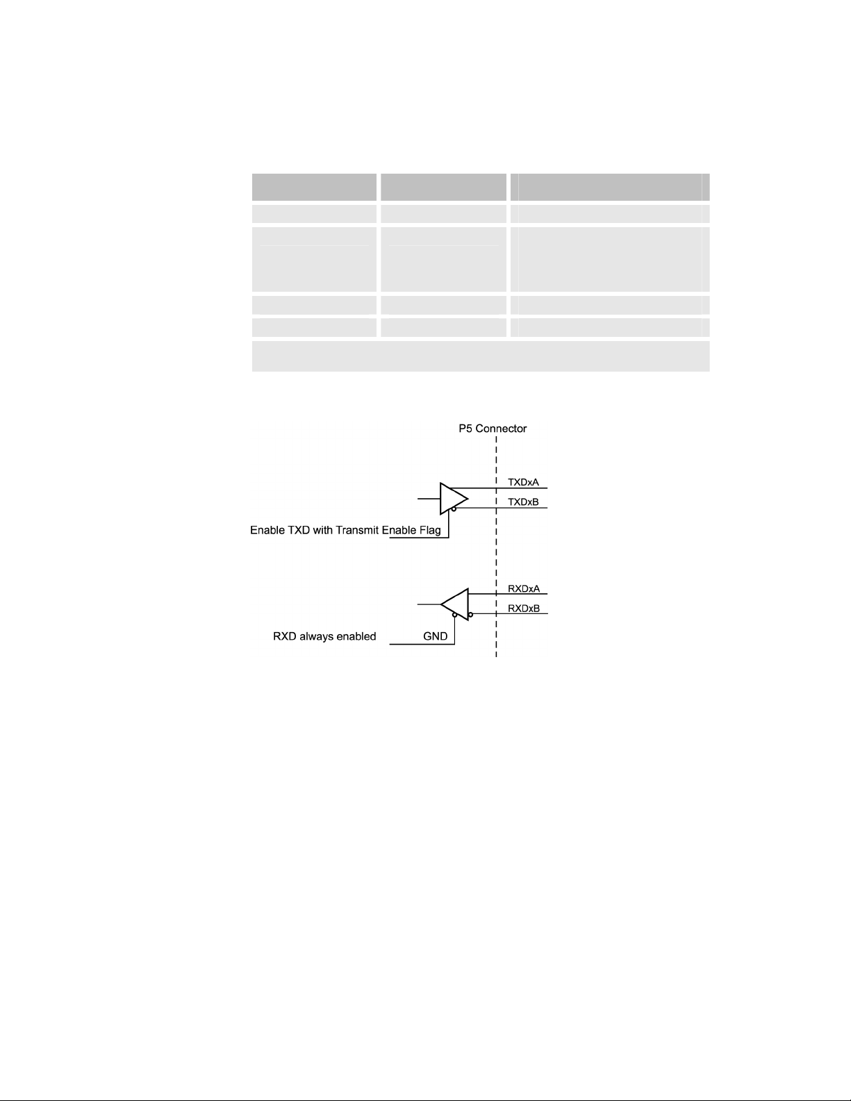
Receive/Transmit Flags
You can set the flow control flags for RS-422 communications mode for each
COM port. Table 2 shows how to set up COM1and COM2.
Receive Flag Transmit Flag COM Function
CLR (0) CLR (0) Not Used (Default)
CLR (0) SET (1) Use for RS-422 Operation:
Full Duplex
Receiver Enabled
Transmitter Enabled
SET (1) CLR (0) Not Used
SET (1) SET (1) Not Used
Note: For bit and flag numbers, see “COM1 Stream Flags” and “COM2 Stream Flags” in
“Appendix B” of the “ACR Motion Controller User’s Guide, Part 2.”
Table 2 Receive/Transmit Flags and COM Functions
Figure 1 ACRCOMM RS-422 Interface Schematic
– 4 – ACRCOMM and ACREXPAXIS User’s Guide
Page 9

ACRCOMM Hardware Setup
The PCI version of the ACRCOMM module (part number SBD12550) does
not require an external power source.
Note: In Figure 2, the black square on the jumpers indicates pin 1.
Jumpers
Figure 2 ACRCOMM Module—PCI version
The PCI version of the ACRCOMM module is not populated with the following
components: F1 through F3, D1 through D3, and PWR2.
If your ACRCOMM module is populated with the above components, you
have an ISA version of the ACRCOMM module, which is incompatible with
the ACR1505.
Warning!
Chapter 1 – ACRCOMM – 5 –
Page 10

The following is a list of the jumper functions on the ACRCOMM module:
Jumper Description
J1 COM1 RS-422 Termination Resistor Select
J2 COM1 RS-422 Termination Resistor Select
J3 COM2 RS-422 Termination Resistor Select
J4 COM2 RS-422 Termination Resistor Select
J5 Not used with the ACR1505
J6 Not used with the ACR1505
J7 COM1 and COM2 Autobaud Detect Enable
J8 Reserved
J9 Reserved
J10 Reserved
Table 3 ACRCOMM Jumper Functions
(see Table 4, on page 6)
(see Table 4, on page 6)
(see Table 4, on page 6)
(see Table 4, on page 6)
(see Table 4, on page 6)
RS-422 Communication Ports Line Terminator Jumpers (J1
thru J4)
These jumpers provide termination resistors for the RS-422signals. For
jumper locations, see Figure 2 on page 5.
Factory Default........................................ Jumpers in
Communication Ports Termination Jumpers
Signal Jumper Termination No Termination
RXD1A/RXD1B J1 Jumper In Jumper Out
TXD1A/TXD1B J2 Jumper In Jumper Out
RXD2A/RXD2B J3 Jumper In Jumper Out
TXD2A/TXD2B J4 Jumper In Jumper Out
Table 4 ACRCOMM RS-422 Termination Jumpers
– 6 – ACRCOMM and ACREXPAXIS User’s Guide
Page 11

Battery Enable Jumpers (J5 and J6)
These jumpers are not used with the ACR1505 Controller.
Autobaud Detect Jumper (J7)
This jumper enables or disables the Autobaud detect feature of the serial
communications channels on the ACRCOMM module. This jumper works in
conjunction with the COM1 Startup Mode (P7013) and COM2 Startup Mode
(P7029) parameters. For more information, see “Miscellaneous Parameters
P6912-P7029” in the “ACR Motion Controller’s User’s Guide Part 2”.
When the COM1/2 Startup Mode parameters (bit 15) are set to zero (factory
default-0), the Autobaud detect is enabled and the Autobaud Detect Jumper
(J7) is ignored.
When the COM1/2 Startup Mode parameters (bit 15) are set to one, the
Autobaud Detect Jumper (J7) defines the autobaud detect function (see
Table 5). For jumper locations, see Figure 2 on page 5.
Factory Default........................................ Autobaud Detect Enabled
Autobaud Detect Jumper
Function J7
Autobaud Detect Enabled ON
Autobaud Detect Disabled OFF
Table 5 ACRCOMM Autobaud Detect Jumper
Chapter 1 – ACRCOMM – 7 –
Page 12

Communications—P5 Connector
There is one 34 pin header provided on the ACRCOMM module for the 2
serial and 1 parallel communications ports. The two serial ports, COM1 and
COM2, can be individually configured as RS-232 or RS-422 interfaces.
Configuration of the COM ports is software selectable by the user.
The following diagram shows the connections for the 3 communications
ports. For jumper locations, see Figure 2 on page 5.
Note: P5 is a 34-pin shrouded male header.
Signal Pin Signal Pin
RXD1 1 TXD1 2
GND 3 MUX1 4
TXD1A 5 TXD1B 6
RXD1A 7 RXD1B 8
RXD2 9 TXD2 10
GND 11 MUX2 12
TXD2A 13 TXD2B 14
RXD2A 15 RXD2B 16
STB 17 AFD 18
ERR 19 INIT 20
SLIN 21 GND 22
PD0 23 PD1 24
PD2 25 PD3 26
PD4 27 PD5 28
PD6 29 PD7 30
ACK 31 BUSY 32
PE 33 SLCT 34
Table 6 ACRCOMM P5 Communications Connector
– 8 – ACRCOMM and ACREXPAXIS User’s Guide
Page 13

CHAPTER TWO
Chapter 2 – EXPAXIS
EXPAXIS
IN THIS CHAPTER
• EXPAXIS Overview............................................................................. 10
• Cables .................................................................................................10
• Encoder Inputs—XP1A, XP1B, and XP1C .........................................12
• Hardware Wiring..................................................................................16
• Module Encoder Pull-ups (Optional) ...................................................18
• Module Software .................................................................................18
Page 14

EXPAXIS Overview
The EXPAXIS Plug-In Module provides additional axes support to the base
ACR1505. A maximum of 8 Axes (Stepper or Servo) and up to 10 Encoders
are available. Additionally, either of the 12 Bit or the 16 Bit ADC option can
be added to this board.
With the fully loaded EXPAXIS option, an ACR1505 can have up to 12
Servo/Stepper Outputs, 14 Incremental Encoders, and 16 Single Ended (8
Differential) ADC Channels.
Plugs on the EXPAXIS module for ENCODERS, DAC/STEPPER and ADC
are different from the base ACR1505 board and caution should be used
when wiring.
Cables
The EXPAXIS module has the following cables:
• XP1A—For ENC10,11,12, and 13
• XP1B—For ENC14,15,16, and 17
• XP1C—For ENC18 and19
• XP9—For Stepper power and ground.
• XP10—For High speed interrupt (INTCAP) inputs. EXP-IN0…EXP-IN7
are TTL logic only.
• XP2—For DAC/STEPPER/ADC I/O. (Corresponds to P2 connector on
the ACR1505 Controller board.
The P2 connector on the ACR1505 Controller board is a DSubminiature connector; whereas XP2 on the EXPAXIS module is a 0.1
inch Center Header ribbon cable. To convert the XP2 connector
(EXPAXIS module) for use with the P2 connector (ACR1505), use the
DXP2 cable assembly (part number PWH80500) supplied with the
EXPAXIS module.
Note: There is no watchdog relay on the EXPAXIS module, so the
watchdog signals are not wired on the DXP2 cable assembly. Therefore,
you must use the watchdog safety contacts from the ACR1505
Controller P2 connector for safeguarding the machine.
– 10 – ACRCOMM and ACREXPAXIS User’s Guide
Page 15

Figure 3 EXPAXIS (9-16) Axis Expansion Board for the ACR1505
Chapter 2 – EXPAXIS – 11 –
Page 16

Encoder Inputs—XP1A, XP1B, and XP1C
The EXPAXIS module accepts any feedback device that supplies either a +5
VDC or +12 VDC differential signal. The most common type of device is a
differential encoder. For common encoder setups, see Table 7. For
connector locations, see Figure 3 on page 11.
There are two 34 pin headers and one 20 pin header provided on the
EXPAXIS module for encoder feedback. The two 34 pin header provide up to
eight (8) axes of encoder feedback (Encoders 10 thru 17). The 20 pin header
provides 2 axes of encoder feedback (Encoder 18 and 19). For connector
locations, see Figure 3 on page 11.
EXPAXIS
Encoder Pull-up Jumper
Length of Cable/Type
Setting
Differential Line Driver Remove Pull-ups 100 ft.(Beldon 9330 Shielded
Open Collector Driver
(No Pull-ups on Encoder)
Open Collector Driver
(With Pull-ups to +5 VDC on
Encoder)
TTL Driver
(+5 VDC Outputs)
Table 7 EPXAXIS Feedback devices
Install Pull-ups and Jumper to
+12 VDC
Install Pull-ups and Jumper
to +5 VDC
(factory Default)
Remove Pull-ups 50 ft. (Beldon 9330 Shielded
Twisted Pair)
75 ft. (Beldon 9330 Shielded
Twisted Pair)
50 ft. (Beldon 9330 Shielded
Twisted Pair)
Twisted Pair)
Note: The EXPAXIS module default settings for the encoder input resistor
types and configuration are not the same as the base ACR1505 board. The
EXPAXIS board is set-up for open-collector drivers with pull-ups to +5V on
the encoder inputs.
When using a single-ended encoder (an encoder without the A-, B-, or Zoutputs), additional pull-ups and pull-down resistors must be added
externally to the EXPAXIS module in order for the EXPAXIS module to read
the encoder signals.
– 12 – ACRCOMM and ACREXPAXIS User’s Guide
Page 17

XP1A and XP1B Connector
The XP1A connector provides access to encoders ENC10, ENC11, ENC12,
and ENC13, which use jumpers J1, J2, J3, and J4 respectively.
The XP1B connector provides access to encoders ENC14, ENC15, ENC16,
and ENC17, which use jumpers J6, J7, J8, and J9 respectively.
XP1A and XP1B are 34-pin shrouded male headers.
Figure 4 XP1A and XP1B ENCODER connector diagram
XP1A Pinout XP1B Pinout
Signal Pin Pin Signal Signal Pin Pin Signal
CHA10 1 2 CHA10' CHA14 1 2 CHA14'
CHB10 3 4 CHB10' CHB14 3 4 CHB14'
MRK10 5 6 MRK10' MRK14 5 6 MRK14'
+5 VDC (100
mA, max)
CHA11 9 10 CHA11' CHA15 9 10 CHA15'
CHB11 11 12 CHB11' CHB15 11 12 CHB15'
MRK11 13 14 MRK11' MRK15 13 14 MRK15'
+5 VDC (100
mA, max)
CHA12 17 18 CHA12' CHA16 17 18 CHA16'
CHB12 19 20 CHB12' CHB16 19 20 CHB16'
MRK12 21 22 MRK12' MRK16 21 22 MRK16'
+5 VDC (100
mA, max)
CHA13 25 26 CHA13' CHA17 25 26 CHA17'
CHB13 27 28 CHB13' CHB17 27 28 CHB17'
MRK13 29 30 MRK13' MRK17 29 30 MRK17'
+5 VDC (100
mA, max)
n/c 33 34 n/c n/c 33 34 n/c
Note: 100 mA maximum, per encoder. Note: 100 mA maximum, per encoder.
7 8 GND +5 VDC (100
mA, max)
15 16 GND +5 VDC (100
mA, max)
23 24 GND +5 VDC (100
mA, max)
31 32 GND +5 VDC (100
mA, max)
7 8 GND
15 16 GND
23 24 GND
31 32 GND
Table 8 EXPAXIS Encoder Input Connectors XP1A and XP1B
Chapter 2 – EXPAXIS – 13 –
Page 18

XP1C Connector
The XP1C connector provides access to encoders ENC18, and ENC19,
which use jumpers J5 and J10 respectively.
XP1C is a 20-pin shrouded male header.
Figure 5 XP1C ENCODER connector diagram
XP1C Pinout
Signal Pin Signal Pin
CHA18 1 MRK18’ 2
CHA18’ 3 +5 VDC
(100 mA, max)
CHB18 5 GND 6
CHB18’ 7 n/c 8
MRK18 9 KEY* 10
CHA19 11 MRK19’ 12
CHA19’ 13 +5 VDC
(100 mA, max)
CHB19 15 GND 16
CHB19’ 17 n/c 18
MRK19 19 n/c 20
* P1C pin 10 is used as a key pin.
4
14
Table 9 EXPAXIS Encoder Input Connector XP1C
XP1C is designed to work in conjunction with a 20 pin ribbon cable
terminated to two (2) standard 9-pin female D-sub type connectors. This 12
inch cable, AMCS part number PWH015, is supplied with the Encoder 18/19
Option.
Ribbon cable conductors 1 thru 9 connect to D-Subminiature Number 1
(conductor 10 is a No Connect). Ribbon cable conductors 11 thru 19 connect
to D- Subminiature Number 2 (conductor 20 is a No Connect). When used in
this manner, the D-sub pinouts are as follows:
– 14 – ACRCOMM and ACREXPAXIS User’s Guide
Page 19

XP1C Y-Cable Pinout
Signal D-Sub No. 1 Signal D-Sub No. 2
CHA18 1 CHA19 1
CHA18’ 2 CHA19’ 2
CHB18 3 CHB19 3
CHB18’ 4 CHB19’ 4
MRK18 5 MRK19 5
MRK18’ 6 MRK19’ 6
+5 VDC 7 +5 VDC 7
GND 8 GND 8
n/c 9 n/c 9
Table 10 EXPAXIS XP1C to two 9 Pin D-Sub Connector Pinout
XP9 Connector
The XP9 connector provides fused, +5 VDC power for open collector stepper
outputs. or connector locations, see Figure 3 on page 11.
XP9 Pinout
Definition Pin Definition Pin
+5 VDC (250 mA, max) 1 +5 VDC (250 mA, max) 2
+5 VDC (250 mA, max) 3 +5 VDC (250 mA, max) 4
GND 5 GND 6
RESERVED 7 RESERVED 8
RESERVED 9 RESERVED 10
GND 11 GND 12
RESERVED 13 RESERVED 14
RESERVED 15 RESERVED 16
Table 11 EXPAXIS XP9 Connector Pinout
Chapter 2 – EXPAXIS – 15 –
Page 20

XP10 Connector
The XP10 connector provides +5 VDC TTL I/O for INTCAP and other special
functions. For connector locations, see Figure 3 on page 11.
Voltage .................................................... +5 VDC
Current Rating......................................... 0.100A maximum
XP10 Pinout
Definition Pin Definition Pin
EXP_IN0 1 EXP_IN1 2
EXP_IN2 3 EXP_IN3 4
EXP_IN4 5 EXP_IN5 6
EXP_IN6 7 EXP_IN7 8
EXP_OUT0 9 EXP_OUT1 10
RESERVED 11 RESERVED 12
RESERVED 13 RESERVED 14
Table 12 EXPAXIS XP10 Connector Pinout
F1 Fuse
When replacing fuses for the EXPAXIS module, use the following tables to
determine the correct part numbers for different vendors.
For fuse location, see Figure 3 on page 11.
Voltage .................................................... +5 VDC
Current Rating.........................................0.250A
Type ........................................................ Littelfuse 454.500
Hardware Wiring
Analog I/O—XP2
The Analog I/O connections on the EXPAXIS module is a 40 Pin Header. To
convert the XP2 connector (EXPAXIS module) for use with the P2 connector
(ACR1505), use the DXP2 cable assembly (part number PWH80500)
supplied with the EXPAXIS module.
Time Delay Fuse
– 16 – ACRCOMM and ACREXPAXIS User’s Guide
Page 21

The XP2 connector is not pin compatible with the P2 connector on the
ACR1505. This is because the ACR1505 has differential stepper outputs and
the watchdog relay.
Important!: Single-ended encoders are not recommended mode of
operation. Noise immunity is significantly reduced.
Note: DXP2 is a standard 40-pin female D-plug.
XP2 is a 40-pin shrouded male header.
Figure 6 XP2 ANALOG I/O connector diagram
DXP2 Pinout
Definition Pin Pin Definition Module
ASIG-8 ( STEP-8 ) 1 20 AGND-8 ( DIR-8 )
ASIG-9 ( STEP-9 ) 2 21 AGND-9 ( DIR-9 ) Module 0
ASIG-10 ( STEP-10 ) 3 22 AGND-10 ( DIR-10 )
ASIG-11 ( STEP-11 ) 4 23 AGND-11 ( DIR-11 )
ASIG-12 ( STEP-12 ) 5 24 AGND-12 ( DIR-12 )
ASIG-13 ( STEP-13 ) 6 25 AGND-13 ( DIR-13 ) Module 1
ASIG-14 ( STEP-14 ) 7 26 AGND-14 ( DIR-14 )
ASIG-15 ( STEP-15 ) 8 27 AGND-15 ( DIR-15 )
AIN-8 9 28 AIN-9
AIN-10 10 29 AIN-11 Module 2
AIN-12 11 30 AIN-13
AIN-14 12 31 AIN-15
( LCUR-8 ) 13 32 ( LCUR-9 ) Module 0
( LCUR-10 ) 14 33 ( LCUR-11 )
( LCUR-12 ) 15 34 ( LCUR-13 ) Module 1
( LCUR-14 ) 16 35 ( LCUR-15 )
RESERVED 17 36 RESERVED None
RESERVED 18 37 RESERVED None
AGND 19 RESERVED Module 2
Note: Pin definitions in parentheses are for stepper modules.
Table 13 EXPAXIS Analog I/O Cable Connector DXP2
Chapter 2 – EXPAXIS – 17 –
Page 22

Module Encoder Pull-ups (Optional)
The ACR1505 can supply +5 VDC or +12 VDC pull-up resistors to each
encoder. Use Table 14 to determine the correct jumper configurations. For
jumper locations, see Figure 3 on page 11.
Factory Default........................................ Configured for +5 VDC for standard
Encoder Pull-Up Jumpers
Encoder Resistor Jumper +5 VDC +12 VDC
10 RP1 JP1 Pins 1 & 2 Pins 2 & 3
11 RP2 JP2 Pins 1 & 2 Pins 2 & 3
12 RP3 JP3 Pins 1 & 2 Pins 2 & 3
13 RP4 JP4 Pins 1 & 2 Pins 2 & 3
14 RP6 JP6 Pins 1 & 2 Pins 2 & 3
15 RP7 JP7 Pins 1 & 2 Pins 2 & 3
16 RP8 JP8 Pins 1 & 2 Pins 2 & 3
17 RP9 JP9 Pins 1 & 2 Pins 2 & 3
18 RP5 JP5 Pins 1 & 2 Pins 2 & 3
19 RP10 JP10 Pins 1 & 2 Pins 2 & 3
Parker encoders
Table 14 EXPAXIS Module Encoder Pull-Up Jumpers
Module Software
To access axes 9 through 16, refer to the software manual for the
commands. In addition, AcroView Version 3.11 and higher can display the
extra parameters, and show and program axes 9 through 16.
– 18 – ACRCOMM and ACREXPAXIS User’s Guide
Page 23

CHAPTER THREE
Additional
Specifications
Chapter 3 – Additional Specifications
IN THIS CHAPTER
• Suggested Stacking of Modules .......................................................20
• Environment and Cooling..................................................................21
Page 24

Suggested Stacking of Modules
Figure 7 Recommended Stacking for ACR1505 Add-on Modules.
– 20 – ACRCOMM and ACREXPAXIS User’s Guide
Page 25

Environment and Cooling
The Add-on modules operates in an ambient temperature range of 0°C
(32°F) to 45°C (113°F). The modules can tolerate atmospheric pollution
degree 2—only
recommended that the cards be mounted in a suitable enclosure.
As you add modules, you must ensure that there are no hot spots created in
the board stack due to airflow impairment.
Airflow impairment might result from cables coming in the way or lack of fan
direction towards the stack. Record the temperature in several places
(especially around I/O and DSP locations) to ensure even heat flow. Impaired
heat flow might cause malfunctions and eventually lead to permanent loss of
function.
Ambient Operating Temperature ............0°C (32°F) to 45°C (113°F)
Storage Temperature.............................. –40°C to 85°C (–40°F to 185°F)
Humidity ..................................................0–95%, non-condensing
Pollution Degree...................................... 2 (per IEC 61010)
Installation Category ............................... 2 (per IEC 61010)
dry, non-conductive pollution is acceptable. Therefore, it is
Chapter 3 – Additional Specifications – 21 –
Page 26

Index
ACRCOMM module.................................................... 3
autobaud detect ................................................... 7
connector, P5....................................................... 8
hardware setup .................................................... 5
jumpers ............................................................... 6
autobaud ......................................................... 7
battery enable ................................................. 7
termination ...................................................... 6
serial communications
MUX flags ........................................................ 3
receive/transmit flags ....................................... 4
add-on modules
cooling ...............................................................21
environment .......................................................21
stacking..............................................................20
autobaud detect ....................................................... 7
environment............................................................21
EXPAXIS module
axes 9-16 ...........................................................18
cables.................................................................10
connector
XP10 ..............................................................16
XP1A ..............................................................13
XP1B ..............................................................13
XP1C ..............................................................14
XP2 ................................................................16
XP9................................................................ 15
fuse ................................................................... 16
jumper
resistor packs ........................................... 12, 18
voltage configuration ................................ 12, 18
watchdog ........................................................... 10
feedback
encoder input ..................................................... 12
fuses
EXPAXIS module................................................. 16
locations ............................................................ 11
inputs
encoder.............................................................. 12
installation category ................................................ 21
jumpers
ACRCOMM module ................................................ 6
pollution degree...................................................... 21
RS-232..................................................................... 3
RS-422 ......................................................... 3, 4, 6, 8
specifications
cooling ............................................................... 21
environmental .................................................... 21
technical support ...................................................... ii
temperature, environment ....................................... 21
watchdog signal...................................................... 10
 Loading...