

Parker Hannifin OEM6250 User Manual
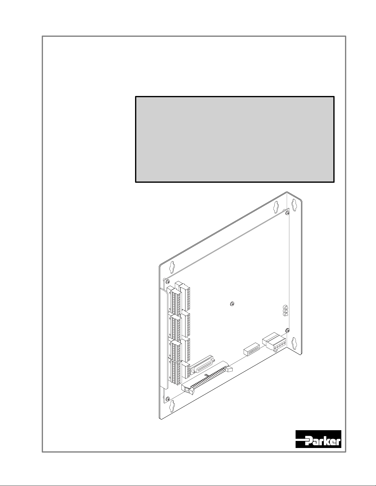
OEM6250 Servo Controller
Installation Guide
Compumotor Division
Compumotor
Parker Hannifin Corporation
p/n 88-016524-01B March 1998
User Information
! !
WARNING
6000 Series products are used to control electrical and mechanical
components of motion control systems. You should test your motion
system for safety under all potential conditions. Failure to do so can result
in damage to equipment and/or serious injury to personnel.
6000 Series products and the information in this user guide are the proprietary property of Parker Hannifin Corporation or its licensers, and
may not be copied, disclosed, or used for any purpose not expressly authorized by the owner thereof.
Since Parker Hannifin constantly strives to improve all of its products, we reserve the right to change this user guide and software and
hardware mentioned therein at any time without notice.
In no event will the provider of the equipment be liable for any incidental, consequential, or special damages of any kind or nature
whatsoever, including but not limited to lost profits arising from or in any way connected with the use of the equipment or this user guide.
© 1991-7, Parker Hannifin Corporation
All Rights Reserved
Motion Architect is a registered trademark of Parker Hannifin Corporation.
Motion Builder, Motion OCX, Servo Tuner, CompuCAM and DDE6000 are trademarks of Parker Hannifin Corporation.
Microsoft and MS-DOS are registered trademarks, and Windows, DDE and NetDDE are trademarks of Microsoft Corporation.
Motion Toolbox is a trademark of Snider Consultants, Inc.
LabVIEW is a registered trademark of National Instruments Corporation.
Technical Assistance
North America and Asia:
Compumotor Division of Parker Hannifin
5500 Business Park Drive
Rohnert Park, CA 94928
Telephone: (800) 358-9070 or (707) 584-7558
Fax: (707) 584-3793
FaxBack: (800) 936-6939 or (707) 586-8586
BBS: (707) 584-4059
e-mail: tech_help@cmotor.com
Internet: http://www.compumotor.com
Automation
Contact your local automation technology center (ATC) or distributor, or ...
Europe
Parker Digiplan
21 Balena Close
Poole, Dorset
England BH17 7DX
Telephone: +44 (0)1202 69 9000
Fax: +44 (0)1202 69 5750
(non-German speaking)
:
Germany, Austria, Switzerland:
HAUSER Elektronik GmbH
Postfach: 77607-1720
Robert-Bosch-Str. 22
D-77656 Offenburg
Telephone: +49 (0)781 509-0
Fax: +49 (0)781 509-176
Product Feedback Welcome
E-mail: 6000user@cmotor.com
Change Summary
OEM6250 Installation Guide
The following is a summary of the primary technical changes to this document.
This book, p/n 88-016524-01B, supersedes 88-016524-01A.
Topic Description
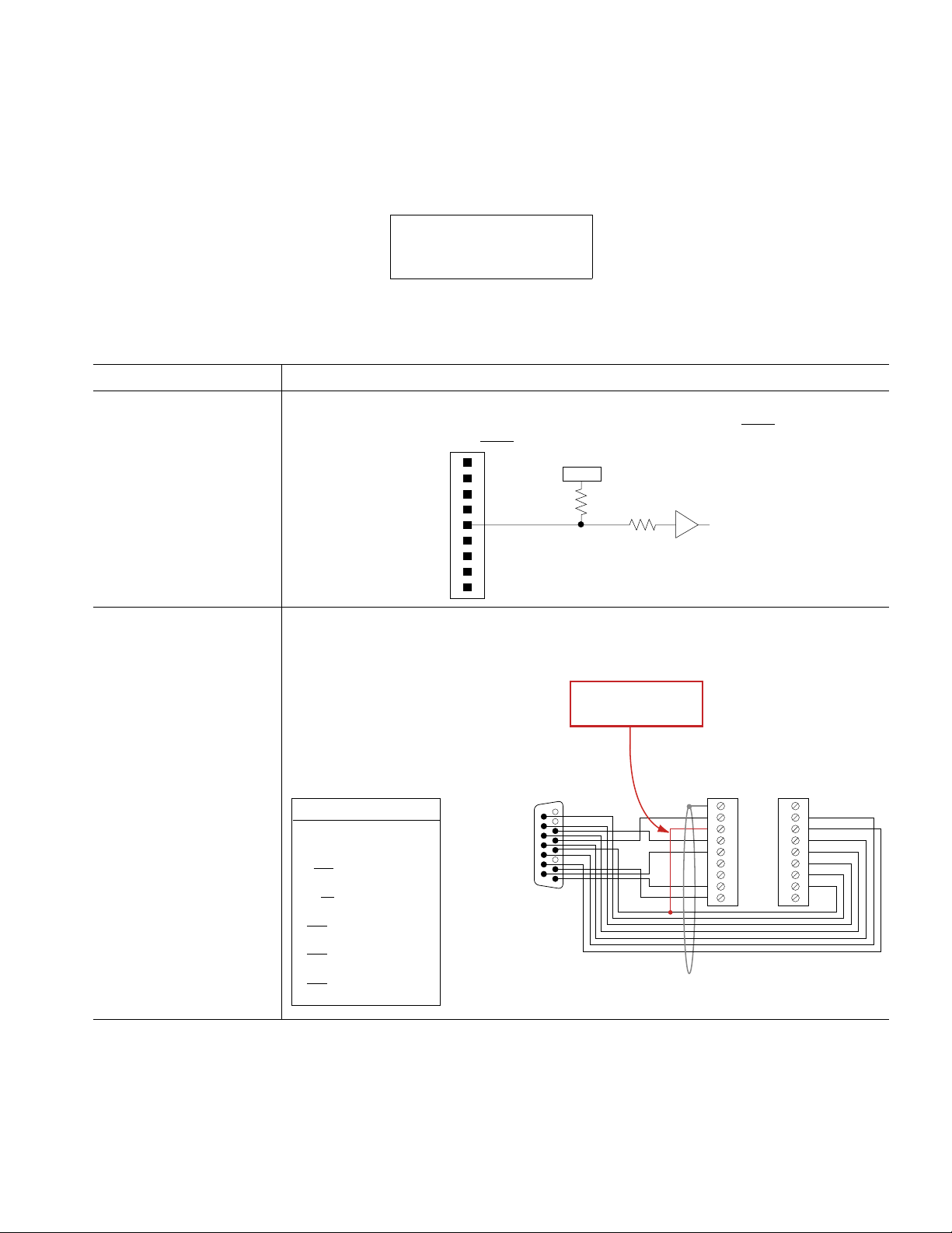
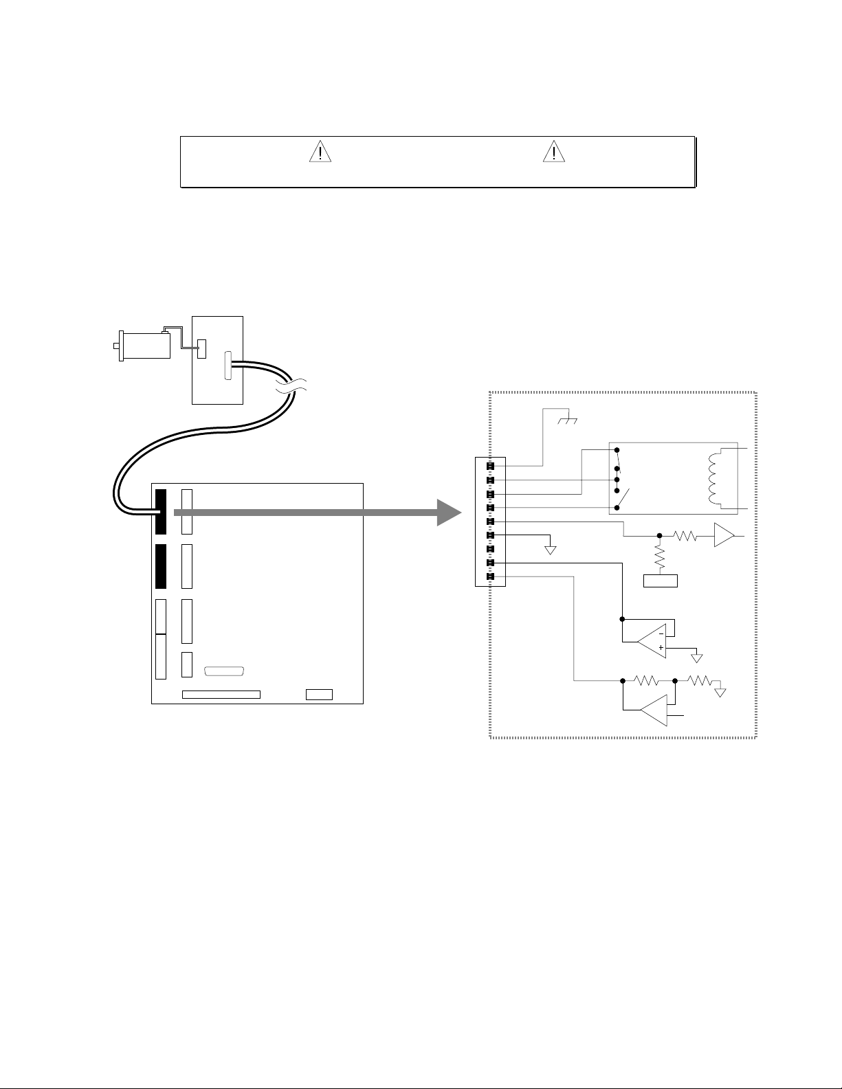
Error Correction:
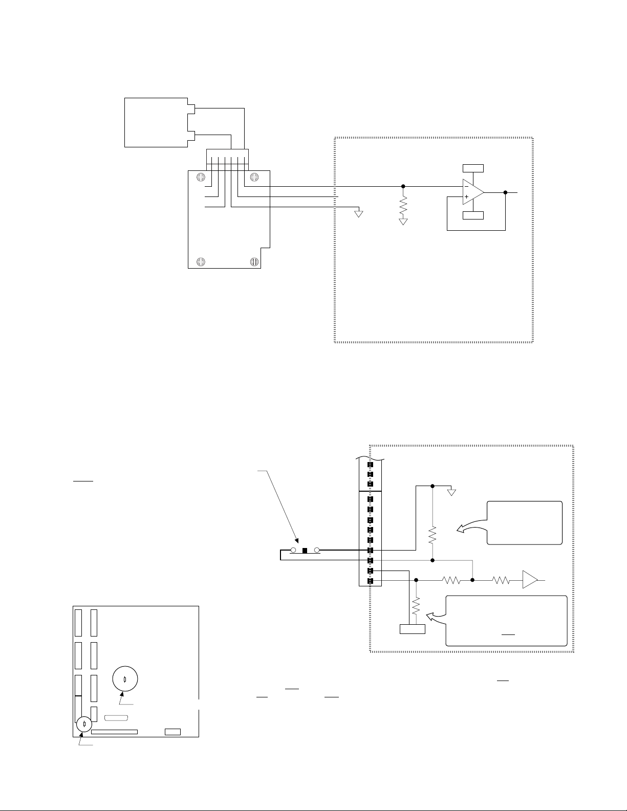
DFT Input Circuit
Revision A incorrectly stated that the drive fault input (DFT pin on the DRIVE connectors)
shared the same circuit design as the limit inputs and trigger inputs. DFT
the AUX-P pullup terminal and
Rev B
March 1998
is not controlled by
is not affected by the R45 resistor. The DFT input circuit is:
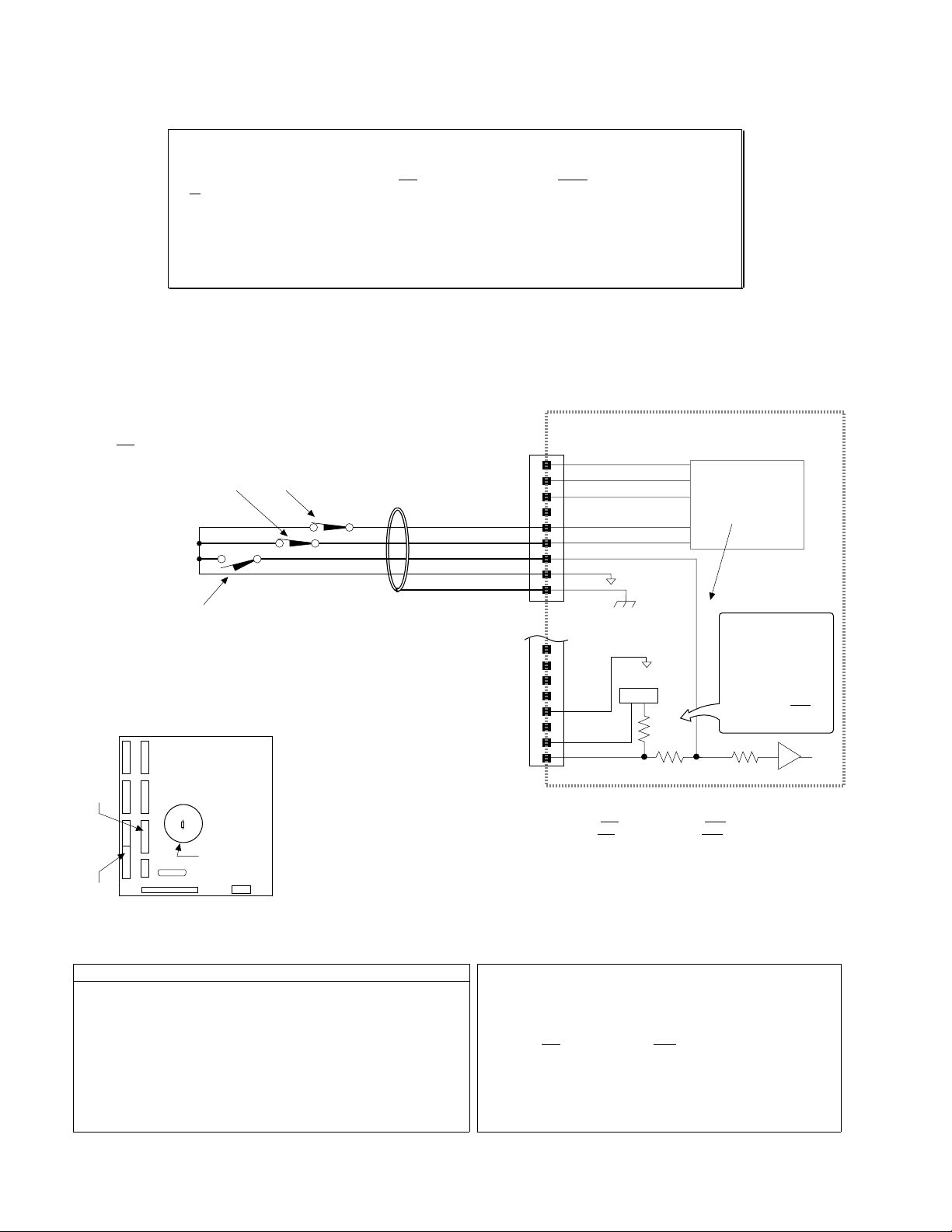
Clarification:
BD-E Drive Connections
SHLD
COM
SHTNC
SHTNO
DFT
AGND
+5VDC
6.8 KW
47 KW
74HCxx
RSVD
CMD–
CMD+
With a BD-E drive connected as illustrated in revision A, the motor has a tendency to lunge for
several revolutions at full torque when power is removed simultaneously from the OEM6250 and
the BD-E drive (as would be the case in a power outage). The correction is to connect the
OEM6250’s SHTNC terminal to the BD-E’s GND terminal (pin 4).
Added connection
to prevent lunge.
BD-E Drive
V2 (pin 1)
V1 (pin 2)
GND (pin 4)
RST (pin 5)
+15V (pin 6)
FT (pin 9)
AOP (pin 10)
AOP (pin 11)
BOP (pin 12)
BOP (pin 13)
ZOP (pin 14)
ZOP (pin 15)
«
«
«
«
«
«
«
«
«
«
«
«
OEM6250
CMD–
CMD+
GND
COM
SHTNO
DFT
A–
A+
B+
B–
Z+
Z–
BD-E Drive
User I/O Connector
815
9
1
NOTE: These connections will work only if
BD-E jumper LK2 is set to position B
(not the factory default position).
OEM6250
DRIVE 1
SHLD
COM
SHTNC
SHTNO
DFT
AGND
RSVD
CMDÐ
CMD+
ENCODER 1
+5V
A+
AÐ
B+
BÐ
Z+
ZÐ
GND
SHLD


ABOUT THIS GUIDE
Chapter 1. Installation
What You Should Have (ship kit)........................................................... 2
Before You Begin..................................................................................... 2
Recommended Installation Process............................................. 2
Electrical Noise Guidelines........................................................... 2
General Specifications............................................................................ 3
Mounting the OEM6250........................................................................... 4
Electrical Connections............................................................................ 5
Grounding System.......................................................................... 5
Serial Communication................................................................... 6
Motor Drivers................................................................................. 7
ANI Analog Input........................................................................... 11
Enable (ENBL) Input — Emergency Stop Switch...................... 11
End-of-Travel and Home Limit Inputs......................................... 12
Encoder......................................................................................... 13
Joystick & Analog Inputs ............................................................. 14
Trigger Inputs................................................................................ 15
General-Purpose Programmable Inputs & Outputs................... 16
RP240 Remote Operator Panel................................................... 20
Input Power................................................................................... 20
Lengthening I/O Cables................................................................ 21
Testing the Installation........................................................................... 22
Tuning the OEM6250............................................................................. 24
What’s Next?......................................................................................... 25
Program Your Motion Control Functions.................................... 25
Chapter 2. Troubleshooting
Troubleshooting Basics......................................................................... 28
Reducing Electrical Noise........................................................... 28
Diagnostic LEDs........................................................................... 28
Test Options.................................................................................. 28
Technical Support......................................................................... 28
Common Problems & Solutions........................................................... 29
Troubleshooting Serial Communication Problems............................. 30
Product Return Procedure.................................................................... 32
Appendix A:
Appendix B:
Index.................................................................................................. 51
Tuning
EMC Installation Guidelines
................................................................... 33
Purpose of This Guide
This document is designed to help you install and troubleshoot your OEM6250 hardware
system. Programming related issues are covered in the 6000 Series Programmer’s Guide and
the 6000 Series Software Reference. (These reference documents are available by ordering the
“OEM6250 MANUALS” ship kit add-on, or they can be downloaded from Compumotor’s web
site at http://www.compumotor.com).
......................... 47
What You Should Know
To install and troubleshoot the OEM6250, you should have a fundamental understanding of:
• Electronics concepts, such as voltage, current, switches.
• Mechanical motion control concepts, such as inertia, torque, velocity, distance, force.
• Serial communication and terminal emulator experience: RS-232C
Related Publications
• 6000 Series Software Reference, Parker Hannifin Corporation, Compumotor Division;
part number 88-012966-01
• 6000 Series Programmer’s Guide, Parker Hannifin Corporation, Compumotor Division;
part number 88-014540-01
• Current Parker Compumotor Motion Control Catalog
• Schram, Peter (editor). The National Electric Code Handbook (Third Edition). Quincy,
MA: National Fire Protection Association
EMC Installation Guidelines
The OEM6250 is sold as a complex component to professional assemblers. As a component,
it is not required to be compliant with Electromagnetic Compatibility Directive 89/336/EEC.
However, Appendix B provides guidelines on how to install the OEM6250 in a manner most
likely to minimize the OEM6250’s emissions and to maximize the OEM6250’s immunity to
externally generated electromagnetic interference.
Online Manuals
This manual (in Acrobat PDF format) is available from our web site: http://www.compumotor.com

CHAPTER ONE
Installation
1
IN THIS CHAPTER
• Product ship kit list
• Things to consider before you install the OEM6250
• General specifications table
• Mounting the OEM6250
• Connecting all electrical components (includes specifications)
• Testing the installation
• Tuning the OEM6250 (refer to Servo Tuner User Guide or to Appendix A)
• Preparing for what to do next
Appendix B provides guidelines on how to install the OEM6250 in a manner most likely
to minimize the OEM6250’s emissions and to maximize the OEM6250’s immunity to
externally generated electromagnetic interference.
What You Should Have
Part Name Part Number
If an item is missing,
call the factory (see
phone numbers on
inside front cover).
One of the following line items:
OEM6250 standard product (with ship kit).............................. OEM6250
OEM6250 product with ANI input board (with ship kit)........... OEM6250-ANI
Ship kit: This manual (
Motion Architect response card ** ............................... 88-013715-01
If you order “OEM6250 MANUALS”, the ship kit would also include:
6000 Series Software Reference
6000 Series Programmer’s Guide
* These manuals are available in electronic form (Adobe Acrobat PDF files)
from our web site — http://www.compumotor.com.
** Motion Architect may be downloaded from our web site.
Before You Begin
The OEM6250 is used to control your system's electrical and mechanical components.
Therefore, you should test your system for safety under all potential conditions. Failure to do
so can result in damage to equipment and/or serious injury to personnel.
(ship kit)
OEM6250 Installation Guide
) * ............. 88-016524-01
* .............................. 88-012966-01
* ............................ 88-014540-01
WARNINGS
¬
The ANI input board
provides two ±10V,
14-bit analog inputs.
To order the ANI input
board separately,
order part number
OPT-OEM6250-A.
Always remove power to the OEM6250 before:
• Connecting any electrical device (e.g., drive, encoder, inputs, outputs, etc.)
• Adjusting the DIP switches or other internal components
Recommended Installation Process
This chapter is
organized
sequentially to best
approximate a typical
installation process.
1. Review the general specifications.
2. Mount the OEM6250.
3. Connect all electrical system components.
4. Test the installation.
5. Mount the motor and couple the load.
6. Tune the OEM6250 for optimum performance. If you are using Servo Tuner, refer to the
instructions in the Servo Tuner User Guide; otherwise, refer to Appendix A (page 33).
7. Program your motion control functions. Programming instructions are provided in the
6000 Series Programmer's Guide and the 6000 Series Software Reference. We recommend
using the programming tools provided in Motion Architect for Windows. You can also
benefit from the optional iconic programming interface called Motion Builder (sold
separately). For information on support software, refer to page 25.
Electrical Noise Guidelines
• Do not route high-voltage wires and low-level signals in the same conduit.
• Ensure that all components are properly grounded.
• Ensure that all wiring is properly shielded.
• Noise suppression guidelines for I/O cables are provided on page 21.
• Appendix B (page 47) provides guidelines on how to install the OEM6250 in a manner
most likely to minimize the OEM6250’s emissions and to maximize the OEM6250’s
immunity to externally generated electromagnetic interference.
2
OEM6250 Installation Guide

General Specifications
Parameter Specification
Power
DC input.................................................................... 5VDC ±5%, 4A minimum
Status LEDs/fault detection...................................... Refer to
Environmental
Operating Temperature .......................................... 32 to 122°F (0 to 50°C)
Storage Temperature............................................... -22 to 185°F (-30 to 85°C)
Humidity................................................................... 0 to 95% non-condensing
Performance
Position Range & Accuracy..................................... Position range: ±2,147,483,648 counts;
Velocity Range, Accuracy, & Repeatability............ Range: 1-2,000,000 counts/sec;
(commanded velocity) Accuracy: ±0.02% of maximum rate;
Acceleration Range.................................................. 1-24,999,975 counts/sec
Motion Trajectory Update Rate............................... See SSFR command description in the
Servo Sampling Update Rate.................................. See SSFR command description in the
Serial Communication
Connection Options.................................................. RS-232C, 3-wire (Rx, Tx & GND on the AUX connector).
Maximum units in daisy-chain................................ 99 (use DIP switch or ADDR command to set individual addresses for each unit)
Communication Parameters................................... 9600 baud (range is 9600-1200—see
Inputs
HOM, POS, NEG, TRG-A, TRG-B, & ENBL ............... HCMOS compatible* with internal 6.8 KW pull-up resistor to AUX-P terminal. Voltage range
DFT ........................................................................... HCMOS compatible* with internal 6.8 KW pull-up resistor to +5VDC. Voltage range for
Joystick inputs: Axes Select, Velocity Select, ...... HCMOS compatible* with internal 6.8 KW pull-ups to +5V; voltage range is 0-24V.
Trigger, Release, and Auxiliary
Encoder..................................................................... Differential comparator accepts two-phase quadrature incremental encoders with differential
16 General-Purpose Programmable Inputs .......... HCMOS compatible* with internal 6.8 KW pull-up resistor to IN-P terminal. As shipped from
(PROGRAMMABLE INPUT/OUTPUT connector)............. the factory, IN-P is internally connected to +5V via resistor R12 (inputs sinking current). To
Analog input channels (JOYSTICK connector)....... Voltage range = 0-2.5VDC; 8-bit A/D converter. Input voltage must not exceed 5V.
Analog Inputs (optional ANI input board)................ Voltage range = ± 10V, 14-bit A/D (OEM6250-ANI or OPT-OEM6250-A product only)
Outputs
8 Programmable Outputs ....................................... Open-collector output with internal 4.7 KW pull-up resistor to OUT-P terminal. Shipped from
(PROGRAMMABLE INPUT/OUTPUT connector)............. factory with these outputs internally pulled up to +5V through a zero ohm resistor – R13. If
+5V Output................................................................ Internally supplied +5VDC. +5V terminals are available on multiple connectors. The amount
Command Out (CMD).............................................. ±10V analog output. 12-bit DAC. Load should be > 2KW impedance.
Shutdown (SHTNO, SHTNC, and COM)................... Shutdown relay output. Max. rating: 175VDC, 0.25A, 3W.
* HCMOS-compatible switching voltage levels: Low £ 1.00V, High ³ 3.25V.
TTL-compatible switching voltage levels: Low £ 0.4V, High ³ 2.4V.
(current requirements depend on the type and amount of I/O used – see page 20).
Diagnostic LEDs
Accuracy: ±0 counts from preset total
Repeatability: ±0.02% of set rate
on page 28
2
6000 Series Software Reference
6000 Series Software Reference
RS-232: Full duplex; XON/XOFF enabled.
AutoBaud
for these inputs is 0-24V. As shipped from the factory, AUX-P is internally connected to +5V
via resistor R45 (input is sinking current). To make the input sink current to a supply other
than +5V, first remove R45 and then connect an external 5-24V supply to the AUX-P terminal.
To source current, first remove R45 and then connect the AUX-P terminal to the GND
terminal. CAUTION: Failure to remove R45 before connecting AUX-P to an external supply,
or to the GND terminal, or to the +5V terminal will damage the OEM6250.
NOTE: As shipped from the factory, the ENBL (enable) input is connected to ground via zeroohm resistor R25, thereby allowing motion. To control the ENBL input with an external switch
(i.e., to use it as an emergency stop input), remove R25.
these inputs is 0-24V.
(recommended) or single-ended outputs.
Maximum voltage = 5VDC. Switching levels (TTL-compatible): Low £ 0.4V, High ³ 2.4V.
Maximum frequency = 1.6 MHz. Minimum time between transitions = 625 ns.
make the inputs sink current to a supply other than +5V, first remove R12 and then connect an
external 5-24V supply to the IN-P terminal. (IN-P can handle 0-24V with max. current of
100 mA.) To source current, first remove R12 and then connect the IN-P terminal to the GND
terminal. CAUTION: Failure to remove R12 before connecting IN-P to an external supply, or
to the GND terminal, or to the +5V terminal will damage the OEM6250. Voltage range = 0-24V.
you remove resistor R13 first, you can pull up these outputs by connecting OUT-P to the +5V
terminal or to an external 5-24V power source. Max. voltage in the OFF state (not sinking
current) = 24V; max. current in the ON state (sinking) = 30mA.
of current available depends on the current that you supply to the +5V terminal on the input
power connector (see page 20).
, page 6), 8 data bits, 1 stop bit, no parity;
Chapter 1. Installation
3
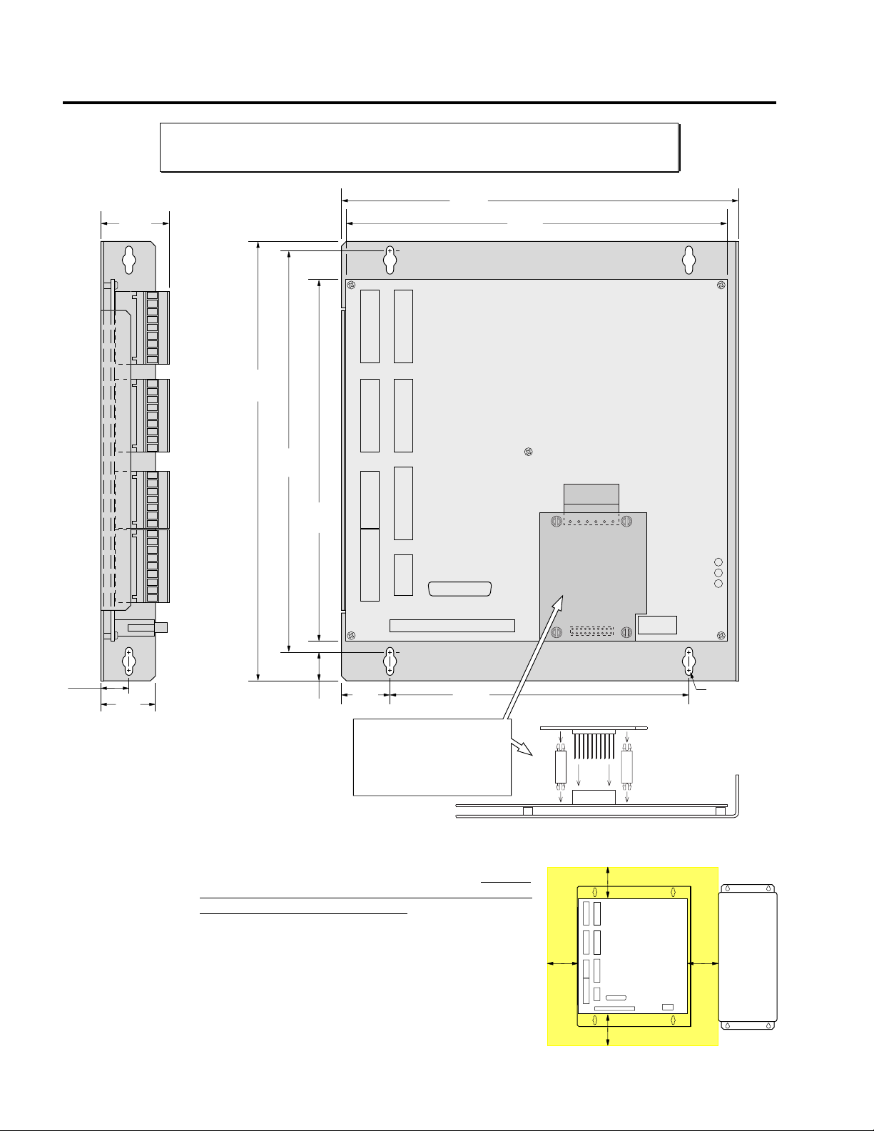
Mounting the OEM6250
Mini
NOTE: The drawing below illustrates the dimensions of the OEM6250 printed circuit board. The
board is shipped from the factory attached to sheet metal which allows either flat mounting or side
mounting of the OEM6250. This board will fit in a 6U rack (if you remove the PCB from the sheet metal).
Max.
Component
Height
1.48
(37.59)
11.00
(279.40)
10.10
(256.54)
9.19
(233.43)
10.01
(254.25)
9.67
(245.62)
6 5 4 3 2 1
0.50
(12.70)
Inches (Millimeters)
Environmental
Considerations
4
1.00
(25.40)
Temperature. Operate the OEM6250 in ambient
temperatures between 32°F (0°C) and 122°F (50°C).
minimum of 2 inches (50.8 mm) of unrestricted air-flow space
around the OEM6250 (see illustration). Fan cooling may be
necessary if adequate air flow is not provided.
Humidity. Keep below 95%, non-condensing.
Airborne Contaminants, Liquids. Particulate
contaminants, especially electrically conductive material,
such as metal shavings and grinding dust, can damage the
OEM6250. Do not allow liquids or fluids to come in contact
with the OEM6250 or its cables.
OEM6250 Installation Guide
0.70
(17.78)
1.00
(25.40)
ANI Option Board
If you ordered the “OEM6250-ANI”
product, this option board is factory
installed. If you ordered the board
separately (p/n “OPT-OEM6250-A”),
install it now. Allow 0.91 (23.11)
mimimum for component height
8.00
(203.20)
Provide a
2.0
(50.8)
Provision for #10
Mounting Screws
(6 Plcs.)
mum Airfow Space = 2 inches
2.0
(50.8)
2.0
(50.8)
2.0
(50.8)
Electrical Connections
Appendix B (page 47) provides guidelines on how to install the OEM6250
in a manner most likely to minimize the OEM6250’s emissions and to
maximize the OEM6250’s immunity to externally generated
electromagnetic interference.
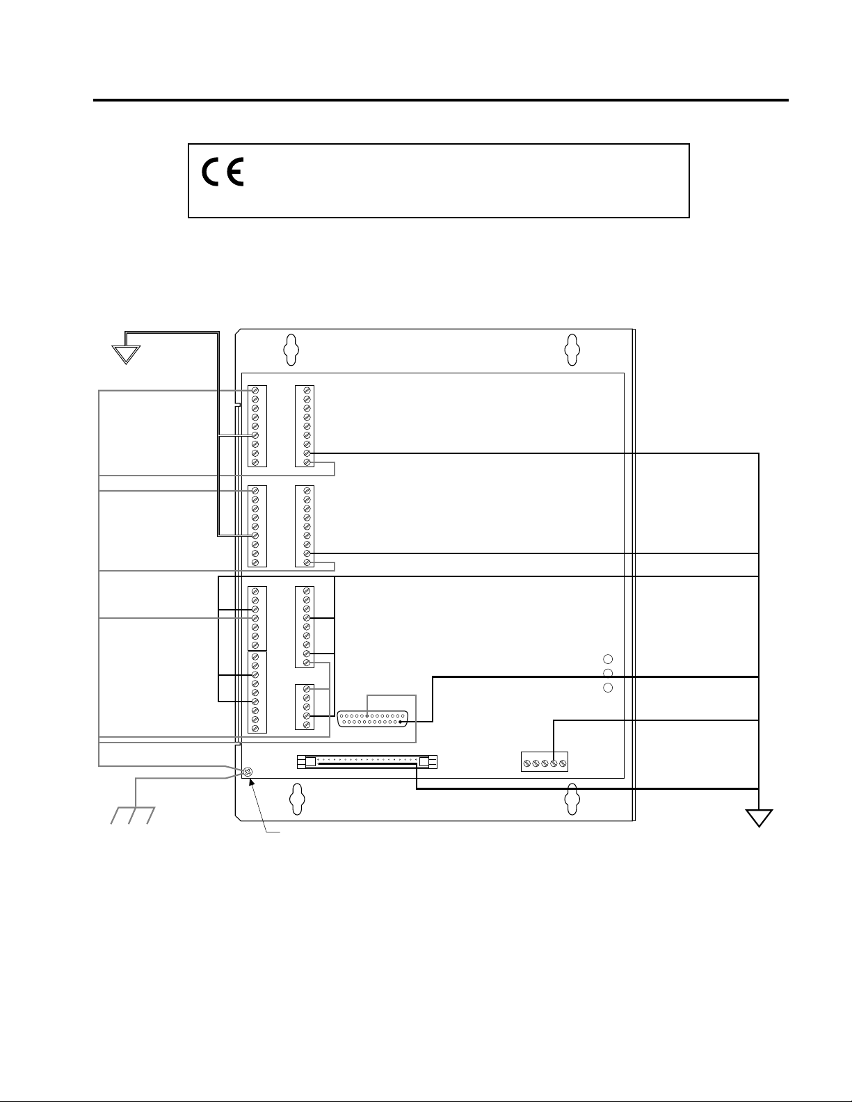
Grounding System
ANALOG
GROUND
SHLD Terminal
SHLD Terminal
SHLD Terminal
SHLD Terminal
SHLD Terminal
SHLD Terminals
SHLD Pin (#8)
Shield Screw
1
AGND Terminals
9
DRIVE 1
DRIVE 2
1
9
1
7
1
9
TH1
SHLD
COM
SHTNC
SHTNO
DFT
AGND
RSVD
CMDCMD+
SHLD
COM
SHTNC
SHTNO
DFT
AGND
RSVD
CMDCMD+
Rx
Tx
GND
SHLD
+5V
OUT-P
IN-P
TRG-A
TRG-B
GND
OUT-A
OUT-B
GND
ENBL
+5V
AUX-P
9
+5V
A+
AB+
BZ+
ZGND
SHLD
1
ENCODER 1
ENCODER 2
9
+5V
A+
AB+
BZ+
ZGND
SHLD
1
LIMITSAUX
9
1POS
1NEG
1HOM
GND
2POS
2NEG
2HOM
GND
SHLD
1
RP240
5
SHLD
Tx
13 1
Rx
GND
+5V
1
25 14
49
50
PROGRAMMABLE INPUT/OUTPUT
JOYSTICK
GND Terminal
GND Terminal
GND Terminals
GND Pin (#14)
DSBL2 DSBL1 STATUS
GND Terminal
1
2
POWER
15
+15V NC -15V GND +5V
GND Pins
(even numbered pins)
EARTH
This connection is critical for providing adequate shielding.
Chapter 1. Installation
DIGITAL
GROUND
5
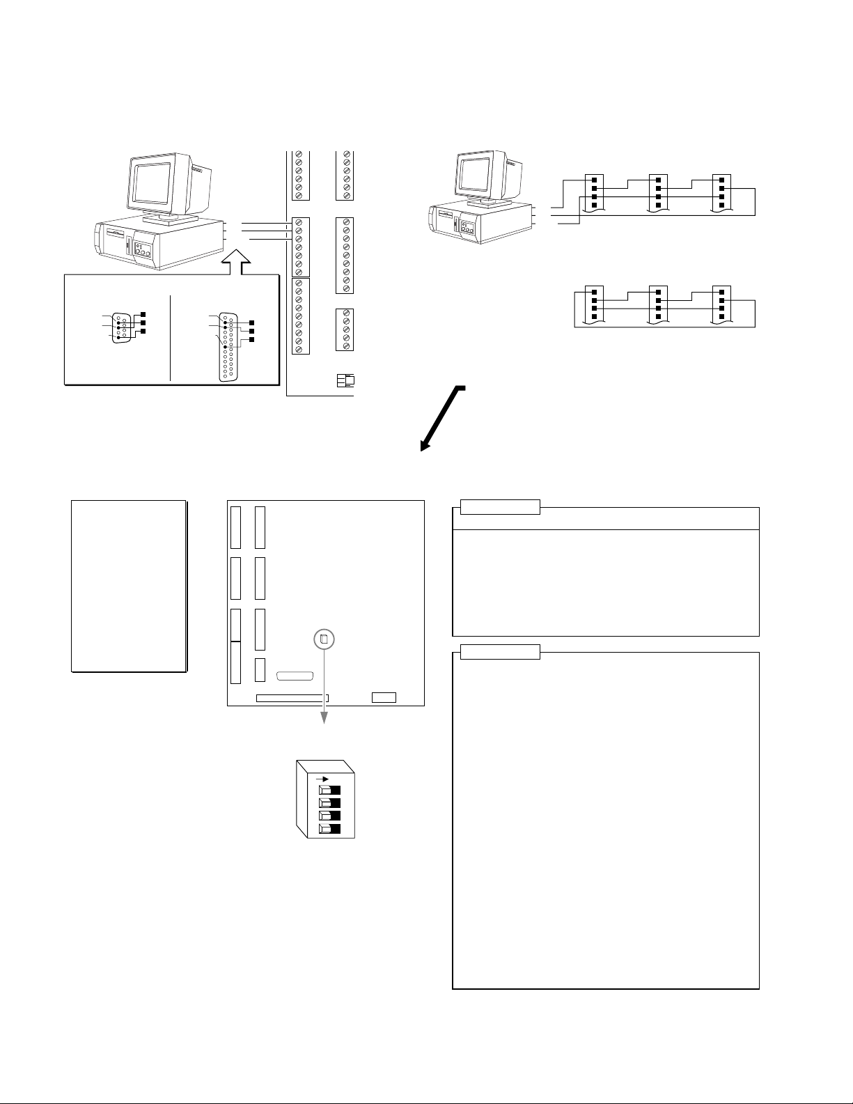
Serial Communication
RS-232C Connections
Tx
Rx
GND
Serial Port Connection
25-Pin COM Port:9-Pin COM Port:
Pin 2 (Rx)
Pin 3 (Tx)
Pin 5 (GND)
NOTE: Max. cable length is 50 ft (15.25 m)
Rx
Tx
GND
Pin 2 (Tx)
Pin 3 (Rx)
Pin 7 (GND)
Rx
Tx
GND
9
1
7
1
9
AUX
Rx
Tx
GND
SHLD
1
9
1
5
1
LIMITS
RP240
49
50
Changing the address and baud rate (OPTIONAL)
Factory Settings
May Be Sufficient
• Device address is
set to zero (if you
are connecting
multiple units in a
daisy-chain, you
can automatically
establish the device
address by using
the ADDR
command).
• Factory default
baud rate is 9600.
DIP Switch
Factory Default Setting Shown
OEM6250
N
O
1234
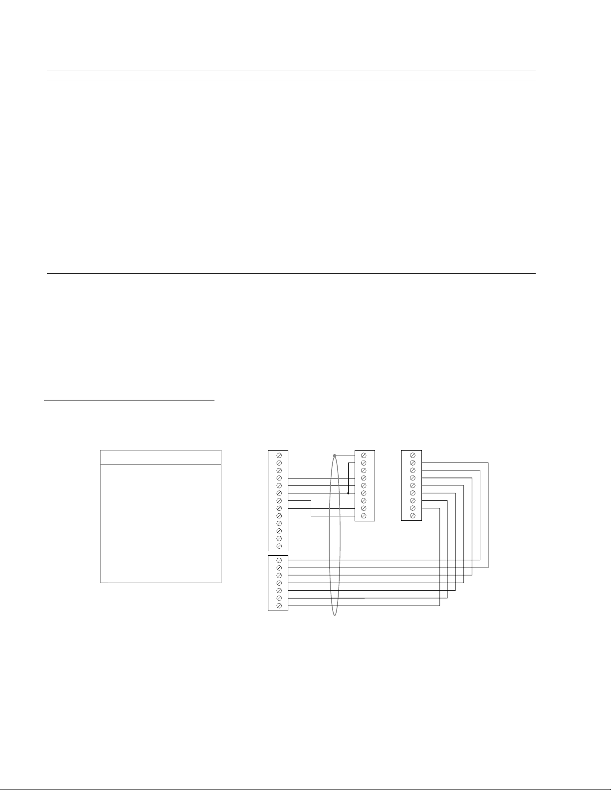
RS-232C Daisy-Chain Connections *
Unit 0 Unit 1 Unit 2
Rx
Tx
GND
Tx
Rx
GND
Daisy Chain to a Computer or Terminal
Stand-Alone Daisy Chain
Be sure to set unique devices addresses for each unit.
*
To set the address, use the DIP switch (see below),
or use the ADDR command (see
ADDRESS
Switch #1 Switch #2 Switch #3 Device Address
OFF OFF OFF Ø (default)
ON OFF OFF 1
OFF ON OFF 2
ON ON OFF 3
OFF OFF ON 4
ON OFF ON 5
OFF ON ON 6
ON ON ON 7
* Device address is checked upon power up or reset.
AUTO BAUD
Switch #4 ON = Auto Baud Enabled
Switch #4 OFF = Auto Baud Disabled (default)
To implement the Auto Baud feature:
The default baud rate is 9600. As an alternative, you can use
this procedure to automatically match your terminal's speed
of 1200, 2400, 4800, or 9600 baud.
1. Set switch 4 to ON.
2. Connect the OEM6250 to the terminal.
3. Power up the terminal.
4. Cycle power to the OEM6250 and immediately press the
space bar several times.
5. The OEM6250 should send a message with the baud rate
on the first line of the response. If no baud rate message
is displayed, verify steps 1-3 and repeat step 4.
6. Change switch 4 to OFF.
7. Cycle power to the OEM6250. This stores the baud rate
in non-volatile memory.
NOTE: If Auto Baud is enabled, the OEM6250 performs its
auto baud routine every time it is powered up or reset. The
OEM6250 is only capable of matching 1200, 2400, 4800, and
9600 baud. Once the baud rate has been determined, the
OEM6250 stores that baud rate in non-volatile memory;
therefore, Switch #4 should be set to the OFF position after
the baud rate has been determined.
SHLD
Unit 0 Unit 1 Unit 2
Rx
Tx
GND
SHLD
6000 Series Software Reference
Rx
Tx
GND
SHLD
Rx
Tx
GND
SHLD
Rx
Tx
GND
SHLD
Rx
Tx
GND
SHLD
).
6
OEM6250 Installation Guide
Motor Drivers
WARNING
REMOVE DC POWER FIRST before connecting or disconnecting the drive.
CONNECTIONS & INTERNAL SCHEMATICS
Drive
Motor
Maximum recommended cable
length is 15 feet (4.56 m).
Use 22 AWG wire.
DRIVE Connector
OEM6250
DRIVE 1
DRIVE 2
AUX
SHLD
COM
SHTNC
SHTNO
DFT
AGND
RSVD
CMD–
CMD+
Chassis Ground
Analog Ground
(AGND)
Internal Schematics
Solid State Relay
Closed if DRIVE¯
Open if DRIVE1
Open if DRIVE¯
Closed if DRIVE1
47 KW
6.8 KW
+5VDC
74HCxx
AGND
-
+
DFT (Drive Fault) input:
HCMOS compatible switching: low £ 1.00V, high ³ 3.25V.
Voltage range = 0-24V.
AGND
Command +
Chapter 1. Installation
7
PIN OUTS & SPECIFICATIONS
(9-pin DRIVE Connector)
Name In/Out Description and Specifications
SHLD — Shield—Internally connected to chassis (earth) ground.
COM — Signal common for shutdown. Not connected to any ground or other COM.
SHTNC OUT Shutdown relay output to drives that require a closed contact to disable the drive. The shutdown relay is active (disabling the
drive) when no power is applied to the OEM6250. When the OEM6250 is powered up, the shutdown relay remains active until
you issue the DRIVE11 command. Max. rating: 175VDC, 0.25A, 3W.
Shutdown active (DRIVE¯¯): this output is internally connected to COM (see schematic above).
Shutdown inactive (DRIVE11): this output is disconnected from COM (see schematic above).
SHTNO OUT Shutdown relay output to drives that require an open contact to disable the drive. The shutdown relay is active (disabling the
drive) when no power is applied to the OEM6250. When the OEM6250 is powered up, the shutdown relay remains active until
you issue the DRIVE11 command. Max. rating: 175VDC, 0.25A, 3W.
Shutdown active (DRIVE¯¯): this output is disconnected from COM (see schematic above).
Shutdown inactive (DRIVE11): this output is internally connected to COM (see schematic above).
DFT IN Drive fault input. Set active level with the DRFLVL command. The drive fault input will not be recognized until you enable the
input functions with the INFEN1 command. HCMOS compatible (Low £ 1.00V, High ³ 3.25V) with internal 6.8 KW pull-up
resistor to internal +5VDC supply.
AGND — Analog ground.
RSVD —
reserved
CMD– IN Command signal return.
CMD+ OUT Command output signal. ±10V analog output. 12-bit DAC. Load should be > 2KW impedance.
CONNECTIONS TO SPECIFIC DRIVES
APEX Series Drives
APEX Series Drive
Enable In
Fault Out
Gnd
Command+
Command–
CHA+
CHA–
CHB+
CHB–
CHZ+
CHZ–
Gnd
Apex Series CHA+ connected to OEM6250’s A–
Apex Series CHA– connected to OEM6250’s A+
«
«
«
«
«
«
«
«
«
«
«
«
NOTE:
OEM6250
SHTNO
DFT
AGND
CMD+
CMD–
A–
A+
B+
B–
Z+
Z–
GND
Vel Int Enable
Enable In
Command+
CommandÐ
Tach Output
APEX Series
Drive
Reset
Gnd
Fault Out
Gnd
Gnd
+15V
Gnd
-15V
CHA+
CHAÐ
CHB+
CHBÐ
CHZ+
CHZÐ
Gnd
OEM6250
SHLD
COM
SHTNC
SHTNO
DFT
AGND
RSVD
CMDCMD+
ENCODER 1
DRIVE 1
+5V
A+
AÐ
B+
BÐ
Z+
ZÐ
GND
SHLD
8
OEM6250 Installation Guide
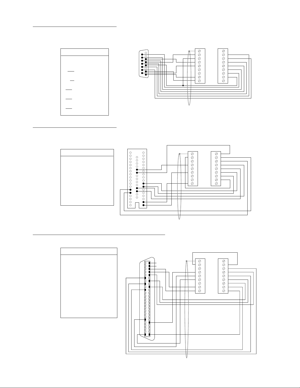
BD-E Drive
BD-E Drive
V2 (pin 1)
V1 (pin 2)
GND (pin 4)
RST (pin 5)
+15V (pin 6)
FT (pin 9)
AOP (pin 10)
AOP (pin 11)
BOP (pin 12)
BOP (pin 13)
ZOP (pin 14)
ZOP (pin 15)
«
«
«
«
«
«
«
«
«
«
«
«
Dynaserv Drives (most)
Dynaserv Drive
A+ (pin 13)
A– (pin 14)
SRVON (pin 23)
Vcc (pin 24)
B+ (pin 29)
B– (pin 30)
Z+ (pin 43)
Z– (pin 44)
VIN (pin 49)
AGND (pin 50)
Dynaserv A+ connected to OEM6250’s A–
Dynaserv A– connected to OEM6250’s A+
OEM6250 GND connected to OEM6250 COM
«
«
«
«
«
«
«
«
«
«
NOTE:
OEM6250
CMD–
CMD+
GND
COM
SHTNO
DFT
A–
A+
B+
B–
Z+
Z–
OEM6250
A–
A+
SHTNO
+5V
B+
B–
Z+
Z–
CMD+
AGND
BD-E Drive
User I/O Connector
815
9
1
NOTE: These connections will work only if
BD-E jumper LK2 is set to position B
(not the factory default position).
Dynaserv Drive
DN1
(50-pin Connector)
1
18
33
19
50
OEM6250
DRIVE 1
SHLD
COM
SHTNC
SHTNO
DFT
AGND
RSVD
CMDÐ
CMD+
ENCODER 1
OEM6250
DRIVE 1 ENCODER 1
SHLD
COM
SHTNC
SHTNO
DFT
AGND
RSVD
CMDCMD+
+5V
A+
AB+
BZ+
ZGND
SHLD
+5V
A+
AÐ
B+
BÐ
Z+
ZÐ
GND
SHLD
Linearserv Drive and Dynaserv DM1004 Drive
Linearserv, DM1004
Com+ (pin 01)
Servo On– (pin 05)
A+ (pin 17)
B+ (pin 19)
Z+ (pin 21)
Agnd-TQ (pin 22)
Vin-TQ (pin 23)
Agnd-VEL (pin 24)
Vin-VEL (pin 25)
Com– (pin 26)
Ready+ (pin 31)
A– (pin 41)
B– (pin 43)
Z– (pin 45)
*
When the Linearserv is in Torque Mode,
connect Linearserv pins 23 & 22 to CMD+
& CMD-. When in the Velocity Mode,
connect pins 25 & 24 are CMD+ & CMD-.
**
Connect Linearserv A+ to OEM6250 A–.
**
Connect Linearserv A– to OEM6250 A+.
Connect OEM6250 GND to OEM6250 COM.
NOTE:
«
«
«
«
«
«
«
«
«
«
«
«
«
«
OEM6250
+5V
SHTNO
A–
**
B+
Z+
CMD-
*
CMD+
*
CMD-
*
CMD+
*
AGND
DFT
A+
**
B–
Z–
Linearserv or DM1004 Drive
CN1
(50-pin Connector)
50 25
26 1
OEM6250
DRIVE 1 ENCODER 1
*
*
SHLD
COM
SHTNC
SHTNO
DFT
AGND
RSVD
CMDCMD+
SHLD
GND
ZÐ
Z+
BÐ
B+
AÐ
A+
+5V
Chapter 1. Installation
9
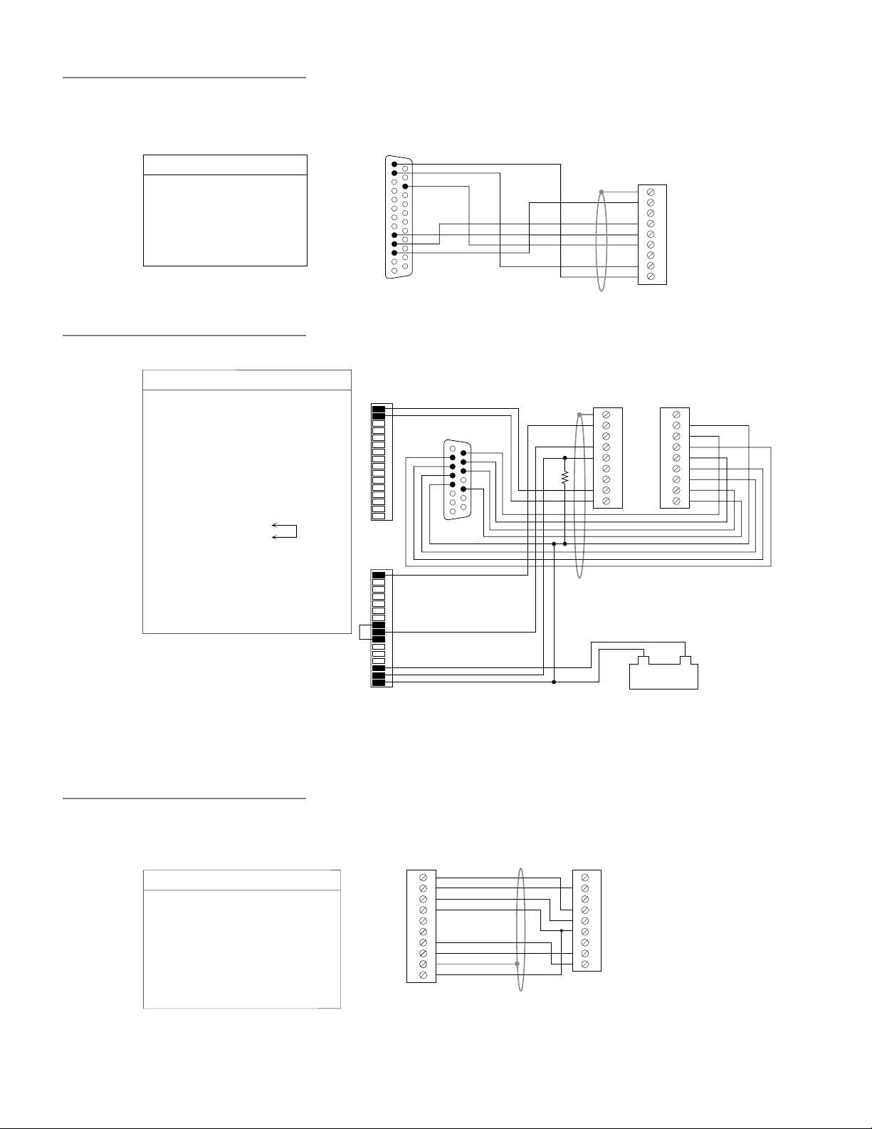
OEM670 Drive
0
0
ENABLE (pin 10)
SV Drive
ENABLE GND (X10 pin 08)
+24V OUT GND (X10 pin 10)
+24V OUT (X10 pin 09)
Fault Output (X10 pin 15)
GND for +24V (X10 pin 16)
*
**
***
OEM670 Drive
CMD+ (pin 1)
CMD– (pin 2)
FAULT (pin 9)
GND (pin 11)
GND (pin 16)
SOLL1+ (X8 pin 01)
SOLL1– (X8 pin 02)
N (X13 pin 02)
B (X13 pin 03)
A (X13 pin 04)
GND (X13 pin 05)
N/ (X13 pin 09)
B/ (X13 pin 10)
A/ (X13 pin 11)
+5V (X13 pin 13)
ENABLE (X10 pin 01)
+24V IN (X10 pin 14)
Connect SV A+ (called “A”) to OEM6250 A–.
Connect SV A– (called “A/”) to OEM6250 A+.
Connect SV’s X10 pins 14 & 16 to an
external 24V power supply. Also connect
SV X10 pin 16 to OEM6250 GND.
Connect a 500½ resistor between the
OEM6250’s GND and DFT terminals.
«
«
«
«
«
«
SV Drive
NOTE:
OEM6250
CMD+
CMD–
DFT
SHTNO
COM
AGND
«
«
«
«
«
«
«
«
«
«
«
«
«
«
«
OEM6250
CMD+
CMD–
Z+
B+
A– *
GND
Z–
B–
A+ *
+5V
Short these
two terminals
COM
SHTNO
+24V **
(Ext. Supply)
DFT ***
GND **
(& Ext. Supply)
OEM670
Drive
1
13
X8
1
16
X10
1
16
14
25
SV Drive
1
8
X13
OEM625
DRIVE 1
SHLD
COM
SHTNC
SHTNO
DFT
AGND
RSVD
CMDÐ
CMD+
OEM6250
DRIVE 1 ENCODER 1
SHLD
COM
9
500
½
15
SHTNC
SHTNO
DFT
AGND
RSVD
CMDCMD+
Power Supply
External 24V
SHLD
GND
ZÐ
Z+
BÐ
B+
AÐ
A+
+5V
+–
TQ Series Drive
ENABLE IN (pin 1)
ENABLE GND (pin 2)
FAULT OUT+ (pin 3)
FAULT OUT– (pin 4)
COMMAND+ (pin 7)
COMMAND– (pin 8)
COMMAND SHLD (pin 9)
10
OEM6250 Installation Guide
TQ Series Drive
GND (pin 10)
OEM6250
«
SHTNO
«
COM
«
DFT
«
AGND
«
CMD+
«
CMD–
«
(cable shield)
«
AGND
TQ Series
Drive
ENABLE IN
ENABLE GND
FAULT OUT+
FAULT OUTÐ
RESET IN
RESET GND
COMMAND+
COMMANDÐ
COMMAND SHLD
GND
OEM625
DRIVE 1
SHLD
COM
SHTNC
SHTNO
DFT
AGND
RSVD
CMDCMD+
ANI Analog Input (OEM6250-ANI or OPT-OEM6250-A product only)
10V A
±
na og
Input Source
Signal Source +
Ground –
6 5 4 3 2 1
N.C.
N.C.
N.C.
ANI Option
Board
Analog Input #1
Analog Input #2
Analog Ground
(same as #1)
Analog
Ground
Analog
Ground
150 KW
¥ Each input is a ±10V analog input with a 14-bit
analog-to-digital converter.
¥ The ANI input is sampled at the servo sampling
rate (see table for SSFR command).
¥ Voltage value reported with the TANI and
ANI commands; Position value (819 counts/volt)
reported with the TPANI and PANI commands.
Internal Schematics
+15V
LF412
-15V
Enable (ENBL) Input — Emergency Stop Switch
AUX Connector
ENBL connected to GND (normally-closed switch).
—You must first remove resistor R25 before you can
(NOTE
use a switch on this input.) If this connection is opened,
motion is killed and the program in progress is terminated.
If the ENBL input is not grounded when motion is
commanded, motion will not occur and the error message
“WARNING: ENABLE INPUT ACTIVE” will be displayed in
the terminal emulator.
OEM6250
AUX
Location of resistor R25.
R45
AUX-P
Location of resistor R45.
As shipped from the factory, AUX-P is internally connected to +5V via resistor R45 (input
is sinking current). To make the ENBL input sink current to a supply other than +5V, first
remove R45 and then connect an external 5-24V supply to the AUX-P terminal. To source
current, first
CAUTION: Failure to remove R45 before connecting AUX-P to an external supply or
to the GND terminal or to the +5V terminal will damage the OEM6250.
NOTE: AUX-P (and R45) are also used by the HOM, NEG, POS, & TRG inputs.
HCMOS compatible (switching levels: low £ 1.00V, high ³ 3.25V).
Voltage range = 0-24V.
remove R45 and then connect the AUX-P terminal to the GND terminal.
+5V
OUT-P
IN-P
TRG-A
TRG-B
GND
OUT-A
OUT-B
GND
ENBL
+5V
AUX-P
+5VDC
Digital
Ground
(GND)
R25
(0 KW)
6.8 KW
R45
Remove R45 before connecting
(0 KW)
AUX-P to an external 5-24VDC
supply (sink current) or to the GND
terminal (source current). Failure
to remove R45 first will damage
the OEM6250.
To control the ENBL
input with a switch,
first remove R25 and
then wire the switch
as shown.
47 KW
Internal Schematic
74HCxx
Chapter 1. Installation
11
End-of-Travel and Home Limit Inputs
• CAUTION: As shipped from the factory, the limit inputs are pulled up to +5V through the R45 resistor. To
use a voltage reference other than +5V, first remove R45 and then use either the on-board +5V terminal
or an external power supply to power the AUX-P pull-up resistor (using both will damage the OEM6250).
• Motion will not occur on an axis until you do one of the following:
- Install end-of-travel (POS & NEG) limit switches.
- Disable the limits with the LH¯ command (recommended only if load is not coupled).
- Change the active level of the limits with the LHLVL command.
• Refer to the
discussions about using end-of-travel limits and homing.
CONNECTIONS & INTERNAL SCHEMATICS
POS & NEG connected to GND (normally-closed switches).
Mount each switch such that the load forces it to open before it
reaches the physical travel limit (leave enough room for the load to
stop). When the load opens the switch, the axis stops at the decel
value set with the LHAD command. The motor will not be able to
move in that same direction until you execute a move in the opposite
direction and
the limits with the LH¯ command, but this is recommended only if the
motor is not coupled to the load). The active level (default is active
low) can be changed with the LHLVL command.
HOM connected to GND (normally-open switch).
The home limit input is used during a homing move, which is initiated
with the HOM command. After initiating the homing move, the controller
waits for the home switch to close, indicating that the load has reached
the “home” reference position. The active level (default is active low) can
be changed with the HOMLVL command. You can also use an encoder’s
Z channel pulse, in conjunction with the home switch, to determine the
home position (this feature is enabled with the HOMZ1 command).
clear the limit by closing the switch (or you can disable
OEM6250
LIMITS
Connector
R45
AUX-P
Location of
resistor R45.
AUX
Connector
Basic Operation Setup
As shipped from the factory, AUX-P is internally connected to +5V via resistor R45 (input is sinking current).
To make the Limit inputs sink current to a supply other than +5V, first remove R45 and then connect an
external 5-24V supply to the AUX-P terminal. To source current, first
terminal to the GND terminal. CAUTION: Failure to remove R45 before connecting AUX-P to an external
supply or to the GND terminal or to the +5V terminal will damage the OEM6250.
NOTE: AUX-P (and R45) are also used by the ENBL & TRG inputs.
HCMOS compatible (switching levels: low £ 1.00V, high ³ 3.25V). Voltage range = 0-24V.
chapter in the
NOTES
6000 Series Programmer’s Guide
LIMITS Connector
AUX Connector
1POS
1NEG
1HOM
GND
2POS
2NEG
2HOM
GND
SHLD
TRG-B
GND
OUT-A
OUT-B
GND
ENBL
+5V
AUX-P
for in-depth
Internal Schematic
All limit inputs share the
same circuit design.
Digital
GND
Chassis
Ground
Remove R45 before
connecting AUX-P to
an external 5-24VDC
Digital
GND
+5VDC
R45
(0 KW)
6.8 KW
remove R45 and then connect the AUX-P
supply (sink current)
or to the GND
terminal (source
current). Failure to
remove R45 first
will damage the
OEM6250.
47 KW
74HCxx
PIN OUTS & SPECIFICATIONS
(LIMITS Connector)
Pin Name In/Out Description Specification for all limit inputs
9
8
7
6
5
4
3
2
1
12
1POS
1NEG
1HOM
GND
2POS
2NEG
2HOM
GND
SHLD
IN
IN
IN
—
IN
IN
IN
—
—
Positive-direction end-of-travel limit input, axis 1.
Negative-direction end-of-travel limit input, axis 1.
Home limit input, axis 1.
Digital ground.
Positive-direction end-of-travel limit input, axis 2.
Negative-direction end-of-travel limit input, axis 2.
Home limit input, axis 2.
Digital ground.
Chassis ground (earth).
OEM6250 Installation Guide
• HCMOS compatible (Low £ 1.00V, High ³ 3.25V) with internal
6.8 KW pull-up resistor to AUX-P terminal. As shipped from the
factory, AUX-P is internally connected to +5V via resistor R45.
To connect AUX-P to a supply other than +5V or to connect to
ground, first remove R45 and then connect AUX-P to an external
5-24V supply or to the GND terminal. Voltage range for these
inputs is 0-24V.
• Active level for HOM is set with HOMLVL (default is active low,
requires n.o. switch).
• Active level for POS & NEG is set with LHLVL (default is active
low, requires n.c. switch).
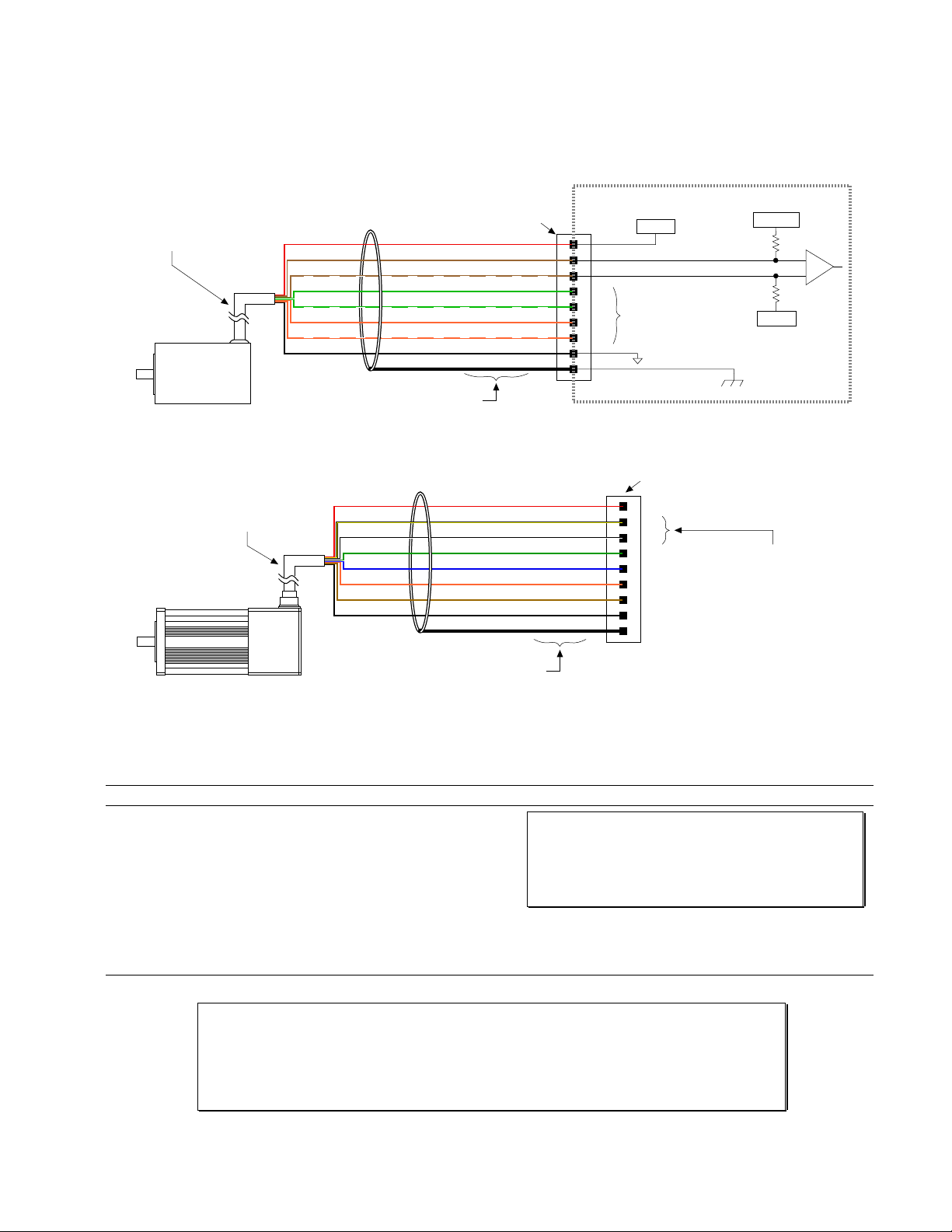
Encoder
CONNECTIONS & INTERNAL SCHEMATICS
Max. Cable Length is 100 feet.
Use 22 AWG wire.
Incremental
Encoder
Wire colors for Compumotor E Series encoders
ENCODER Connector
+5VDC
A Channel +
A Channel –
B Channel +
B Channel –
Z Channel +
Z Channel –
Ground
Shield
Red
Brown
Brown/White
Green
Green/White
Orange
Orange/White
Black
Shield
+5VDC
+5V
A+
A–
B+
B–
Same Circuit
as A Channel
Z+
ZGND
SHLD
Digital Ground
ENCODER Connector
Internal Schematic
+1.8VDC
22 KW
22 KW
+5VDC
Chassis Ground
Encoder Cable
SM Motor
PIN OUTS & SPECIFICATIONS
Pin Name In/Out Description
9
+5V
8
A+
7
A–
6
B+
5
B–
4
Z+
3
Z–
2
GND
1
SHLD
OUT
IN
IN
IN
IN
IN
IN
-----
-----
+5VDC output to power the encoder.
A+ Channel quadrature signal input.
A– Channel quadrature signal input.
B+ Channel quadrature signal input.
B– Channel quadrature signal input.
Z+ Channel signal input.
Z– Channel signal input.
Digital ground.
Shield
—Internally connected to chassis ground (earth).
+5VDC
A Channel –
A Channel +
B Channel +
B Channel –
Z Channel +
Z Channel –
Ground
Shield
Wire colors
(ENCODER Connector)
Red
Yellow
White
Green
Blue
Orange
Brown
Black
Shield
+5V
A+
A–
B+
B–
Z+
ZGND
SHLD
NOTE: Be sure to connect
the A– encoder lead (yellow)
to the A+ terminal, and
connect the A+ encoder lead
(white) to the A– terminal.
Specification for all encoder inputs
Differential comparator accepts two-phase quadrature
incremental encoders with differential (recommended) or
single-ended outputs. Max. frequency is 1.6 MHz. Minimum
time between transitions is 625 ns. TTL-compatible voltage
levels: Low £ 0.4V, High ³ 2.4V. Maximum input voltage is
5VDC.
Requirements for Non-Compumotor Encoders
• Use incremental encoders with two-phase quadrature output. An index or
Differential outputs are recommended.
• It must be a 5V (< 200mA) encoder to use the OEM6250’s +5V output. Otherwise, it must be separately
powered with TTL-compatible (low £ 0.4V, high ³ 2.4V) or open-collector outputs.
• If you are using a single-ended encoder, leave the A–, B– and Z– terminals on the OEM6250 unconnected.
Z channel
output is optional.
Chapter 1. Installation
13
 Loading...