

Parker Hannifin Needle Valves User Manual
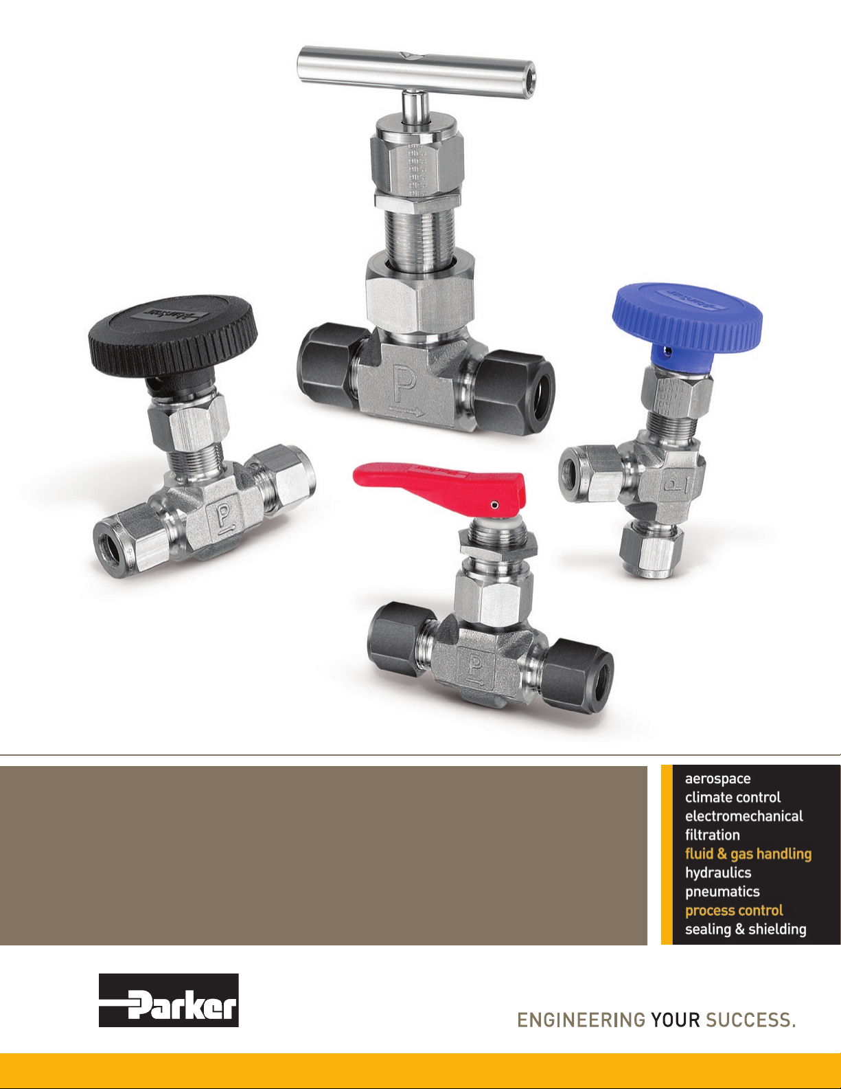
Needle Valves
Catalog 4110-NV December 2010
Overview
Catalog 4110-NV
ii
Parker Hannifin Corporation
Instrumentation Products Division
Jacksonville, AL USA
http://www.parker.com/ipdus
Catalog 4110-NV
Table of Contents
Description ...........................................................................................Page
V Series Needle Valves – Integral Bonnet, 5,000 PSI Maximum* ............... 2
U Series Needle Valves – Union Bonnet, 6,000 PSI Maximum* ...............12
VQ Series Toggle Valves – 600 PSI Maximum* ......................................... 18
NP6 Series Needle Valves – Screwed Bonnet, 6,000 PSI Maximum* ....... 24
SN6 Series Needle Valves – Integral Bonnet, 6,000 PSI Maximum* ......... 28
PV Series Needle Valves – Rising Stem Plug Valve,
6,000 PSI Maximum* .......................................................................... 32
MPN Series Needle Valves – 20,000 PSI Maximum* ................................ 36
V
U
VQ
NP6
SN6
PV
MPN
Sample Cylinders and Accessories ...........................................................44
End Connections ....................................................................................... 50
Offer of Sale .............................................................................................. 51
* Actual pressure rating will be determined by the valve configuration, body material, seat material and other factors.
WARNING – USER RESPONSIBILITY
FAILURE OR IMPROPER SELECTION OR IMPROPER USE OF THE PRODUCTS DESCRIBED HEREIN OR RELATED ITEMS CAN CAUSE DEATH, PERSONAL INJURY AND
PROPERTY DAMAGE.
This document and other information from Parker-Hannifin Corporation, its subsidiaries and authorized distributors provide product or system options for further investigation by users
having technical expertise.
The user, through its own analysis and testing, is solely responsible for making the final selection of the system and components and assuring that all performance, endurance,
maintenance, safety and warning requirements of the application are met. The user must analyze all aspects of the application, follow applicable industry standards, and follow the
information concerning the product in the current product catalog and in any other materials provided from Parker or its subsidiaries or authorized distributors.
To the extent that Parker or its subsidiaries or authorized distributors provide component or system options based upon data or specifications provided by the user, the user is responsible
for determining that such data and specifications are suitable and sufficient for all applications and reasonably foreseeable uses of the components or systems.
Offer of Sale
The items described in this document are hereby offered for sale by Parker-Hannifin Corporation, its subsidiaries or its authorized distributors. This offer and its acceptance are governed by
the provisions stated in the detailed “Offer of Sale” elsewhere in this document or available at www.parker.com/ipdus.
© Copyright 2010 Parker Hannifin Corporation. All Rights Reserved.
Cyl &
Acc
End
Conn
1
Parker Hannifin Corporation
Instrumentation Products Division
Jacksonville, AL USA
http://www.parker.com/ipdus
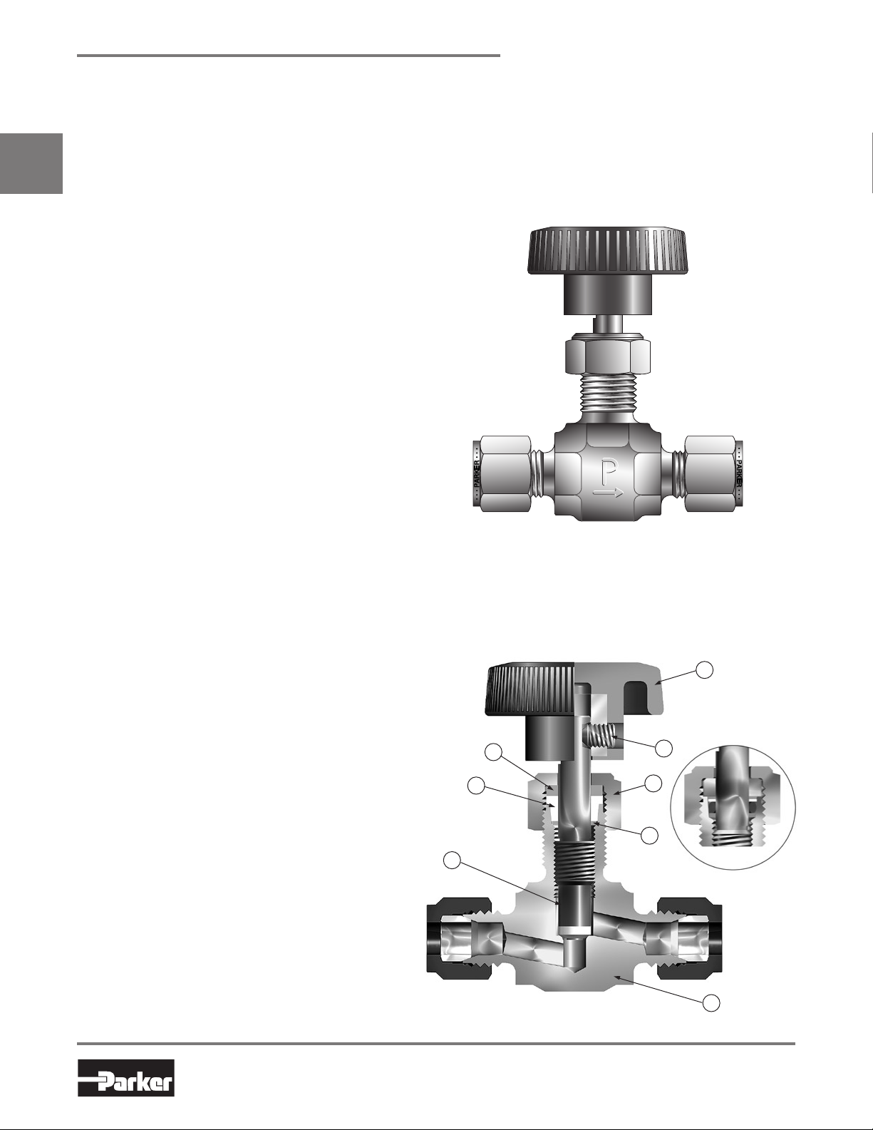
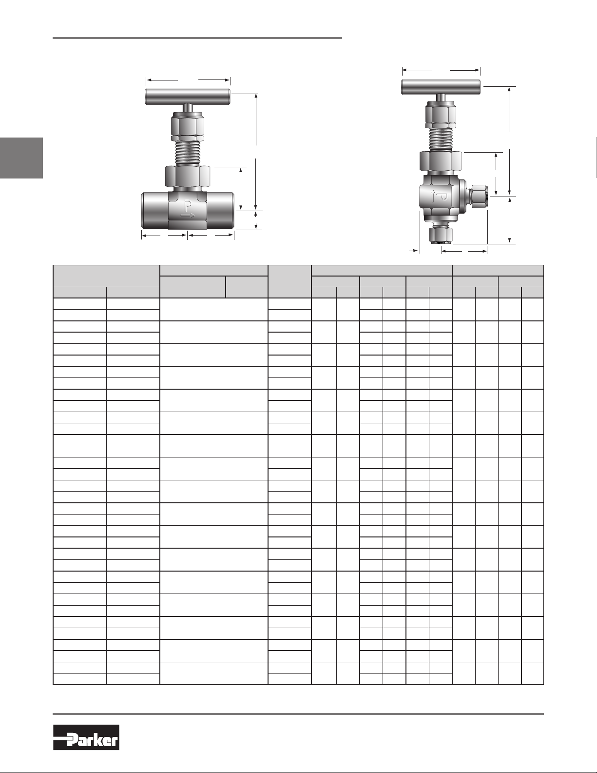
V Series Needle Valves
Introduction
Parker V Series Needle Valves are designed for positive leak tight shut-off and regulation of fluids in process,
power, and instrumentation applications. With a wide variety of port sizes and styles, temperature capabilities
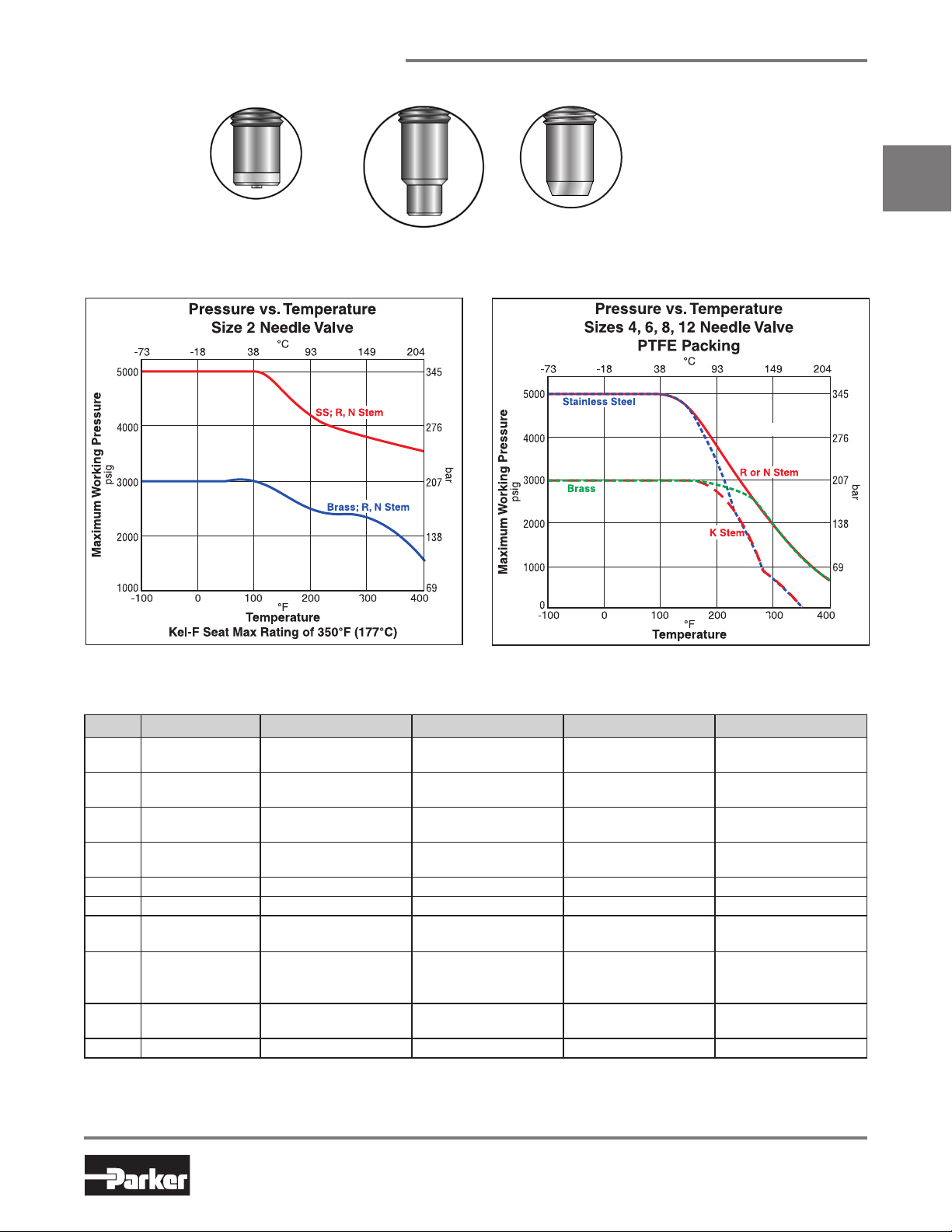
ranging from -65°F to 450°F (-54°C to 232°C) and pressures to 5000 psig (345 bar), V Series Needle Valves
V
provide the user with the utmost in flexibility when designing miniaturized tubing or piping systems.
Features
Choice of three stem types:
R-Stem – All metal, blunt stem tip
N-Stem – All metal, tapered needle stem tip
K-Stem – PCTFE stem tip
Differential hardness between the strain
hardened stem and cold formed body threads
provides improved cycle life
Choice of PTFE packing or elastomeric O-ring
stem seals
316 Stainless Steel, Steel, Brass and Monel
Alloy 400 construction
Inline and angle patterns
Wide variety of US Customary and SI ports
Panel mountable
100% factory tested
Optional color coded handles
®
Catalog 4110-NV
Specifications
Pressure Ratings:
316 Stainless Steel: 5000 psig (345 bar) CWP
Brass, Steel and Monel® Alloy 400:
3000 psig (207 bar) CWP
Orifice: 0.078" to 0.312" (2.0mm to 7.9mm)
C
: 0.12 to 1.90
V
Port size: 1/8" to 3/4" (3mm to 12mm)
Temperature Ratings:
Stainless Steel and Monel® Alloy 400:
-65°F to 450°F (-54°C to 232°C)
Brass: -65°F to 400°F (-54°C to 204°C)
Steel: -20°F to 350°F (-29°C to 177°C)
PTFE Packing:
-65°F to 450°F (-54°C to 232°C)
PCTFE Stem Tip:
-65°F to 350°F (-54°C to 177°C)
Nitrile Rubber Stem Seal:
-30°F to 250°F (-34°C to 121°C)
Fluorocarbon Rubber Stem Seal:
-15°F to 400°F (-26°C to 204°C)
Ethylene Propylene Rubber Stem Seal:
-70°F to 275°F (-57°C to 135°C)
Note: When combining body, seat and seal materials, the most
restrictive temperature rating becomes the limiting factor on
temperature range.
®
Monel
Alloy 400 is the registered trademark of Special
Metals Corporation.
Model Shown: 4Z-V4LK-SS
Materials of Construction
(with PTFE Packing)
8
6
7
Model Shown: 4Z-V4LK-SS
5
2
4
3
O-Ring Stem Seal
1
2
Parker Hannifin Corporation
Instrumentation Products Division
Jacksonville, AL USA
http://www.parker.com/ipdus
Catalog 4110-NV
Stem Types
V Series Needle Valves
V
K
PCTFE tipped
Pressure vs. Temperature
Note: To determine MPa, multiply bar by 0.1
N
Needle (2-1/2°)
R
Blunt (30°)
Materials of Construction (with PTFE Packing)
Item # Part Description Stainless Steel Brass Steel Monel® Alloy 400
1 Body
2 Packing Nut
3 Handle*
4
5 Handle Screw Stainless Steel Stainless Steel Stainless Steel Stainless Steel
6 Packing** PTFE PTFE PTFE PTFE
7
7A
8
9 Panel Nut*** 316 Stainless Steel 316 Stainless Steel 316 Stainless Steel 316 Stainless Steel
* Handles for V8 and V12 Series Valves with R and N Stems are aluminum T-bars.
** Optional O-ring elastomeric stem seals are available – See How to Order.
*** Panel Nut is nickel plated brass on V2 Series Valves. Panel Nuts must be ordered separately – see page 10.
Lubrication: Perfluorinated Polyether
Lower Packing
Washer
Stem
( R and N Stem)
Stem
(K Stem)
Upper Packing
Washer
ASTM A 182
Type F316
ASTM A 479
Type 316
Nylon 6/6
with SS insert
ASTM A 479
Type 316
ASTM A 276
Type 316
ASTM A 276
Type 316,
with PCTFE
Brass Brass Brass Brass
ASTM B 283
Alloy C37700
ASTM A 479
Type 316
Nylon 6/6
with SS insert
ASTM A 479
Type 316
ASTM A 276
Type 316
ASTM A 276
Type 316,
with PCTFE
ASTM A 576
Grade 1214
ASTM A 479
Type 316
Nylon 6/6
with SS insert
ASTM A 479
Type 316
ASTM A 276
Type 316
ASTM A 276
Type 316,
with PCTFE
ASTM B 564
Alloy N04400
ASTM A 479
Type 316
Nylon 6/6
with SS insert
ASTM B 164
Alloy N04400
ASTM B 164
Alloy N04400
ASTM B 164
with PCTFE
3
Parker Hannifin Corporation
Instrumentation Products Division
Jacksonville, AL USA
http://www.parker.com/ipdus
V Series Needle Valves
B
1.38
(35.1)
Max Open 2.22 (56.4)
Min Close 2.02 (51.3)
A
.43 (10.9)
.41
(10.4)
B
A
1.38
(35.1)
Max Open 2.22 (56.4)
Min Close 2.02 (51.3)
.41 (10.4)
.43 (10.9)
BA
.94
(23.9)
Max Open 2.25 (57.2)
Min Close 1.93 (49.0)
.31 (7.9)
.43 (10.9)
B
.31
(7.9)
.94
(23.9)
Max Open 2.25 (57.2)
Min Close 1.93 (49.0)
A
.43 (10.9)
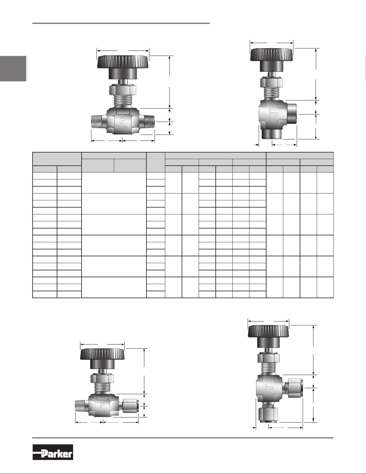
V2 Series Dimensions / Flow Data
V
Panel Hole Diameter:
0.45 (11.4)
Max Panel Thickness:
0.25 (6.4)
Catalog 4110-NV
Model Shown:
2M-V2LN-SS
Basic
Part Number
Inline Angle Inch mm C
2A-V2LR 2A-V2AR
End Connections
Inlet
(Port 1)
Outlet
(Port 2)
1/8" Compression A-LOK
Stem
Orifice Inline Angle A† B†
Type
Blunt
®
0.078 2.0
Model Shown:
2F-V2AR-V-SS
Flow Data Dimensions
XT* C
V
0.12 0.78 0.14 0.67
V
2A-V2LK 2A-V2AK PCTFE 0.13 0.83 0.14 0.63
2F-V2LR 2F-V2AR
1/8" Female NPT
Blunt
0.13 0.61 0.16 0.49
0.093 2.4
2F-V2LK 2F-V2AK PCTFE 0.12 0.73 0.17 0.54
2M-V2LR 2M-V2AR
1/8" Male NPT
Blunt
0.13 0.61 0.16 0.49
0.093 2.4
2M-V2LK 2M-V2AK PCTFE 0.12 0.73 0.17 0.54
2Z-V2LR 2Z-V2AR
1/8" Compression CPI™
Blunt
0.12 0.78 0.14 0.67
0.078 2.0
2Z-V2LK 2Z-V2AK PCTFE 0.13 0.83 0.14 0.63
4A-V2LR 4A-V2AR
1/4" Compression A-LOK
Blunt
®
0.078 2.0
0.12 0.78 0.14 0.67
4A-V2LK 4A-V2AK PCTFE 0.13 0.83 0.14 0.63
4Z-V2LR 4Z-V2AR
1/4" Compression CPI™
Blunt
0.12 0.78 0.14 0.67
0.078 2.0
4Z-V2LK 4Z-V2AK PCTFE 0.13 0.83 0.14 0.63
* Tested in accordance with ISA S75.02. Gas flow will be choked when P1 - P2 / P1 = XT.
† For CPI™ and A-LOK®, dimensions are measured with nuts in the finger tight position.
XT* Inch mm Inch mm
1.01 25.7 1.01 25.72A-V2LN 2A-V2AN Needle 0.12 0.80 0.14 0.63
0.94 23.9 0.94 23.92F-V2LN 2F-V2AN Needle 0.12 0.66 0.18 0.39
0.75 19.1 0.75 19.12M-V2LN 2M-V2AN Needle 0.12 0.66 0.18 0.39
1.01 25.7 1.01 25.72Z-V2LN 2Z-V2AN Needle 0.12 0.80 0.14 0.63
1.09 27.7 1.09 27.74A-V2LN 4A-V2AN Needle 0.12 0.80 0.14 0.63
1.09 27.7 1.09 27.74Z-V2LN 4Z-V2AN Needle 0.12 0.80 0.14 0.63
Dimensions in inches/millimeters are
for reference only, subject to change.
V4 Series
Model Shown:
4M4Z-V4LK-SS
( ) Denotes dimensions in millimeters
Panel Hole Diameter:
0.52 (13.2)
Max Panel Thickness:
0.25 (6.4)
Model Shown:
4A-V4AN-BN-B
4
Parker Hannifin Corporation
Instrumentation Products Division
Jacksonville, AL USA
http://www.parker.com/ipdus
Catalog 4110-NV
V4 Series Dimensions / Flow Data
V Series Needle Valves
Basic
Part Number
Inline Angle Inch mm C
2A-V4LR 2A-V4AR
End Connections
Inlet
(Port 1)
Outlet
(Port 2)
1/8" Compression A-LOK
Stem
Orifice Inline Angle A† B†
Type
Blunt
®
0.078 2.0
Flow Data Dimensions
XT* C
V
V
0.12 0.52 0.15 0.64
2A-V4LK 2A-V4AK PCTFE 0.14 0.66 0.17 0.49
2F-V4LR 2F-V4AR
1/8" Female NPT
Blunt
0.43 0.77 0.55 0.63
0.176 4.5
2F-V4LK 2F-V4AK PCTFE 0.45 0.55 0.58 0.68
2M-V4LR 2M-V4AR
1/8" Male NPT
Blunt
0.28 0.67 0.36 0.55
0.125 3.2
2M-V4LK 2M-V4AK PCTFE 0.29 0.51 0.37 0.59
2Z-V4LR 2Z-V4AR
1/8" Compression CPI
Blunt
™
0.078 2.0
0.12 0.52 0.15 0.64
2Z-V4LK 2Z-V4AK PCTFE 0.14 0.66 0.17 0.49
4A-V4LR 4A-V4AR
1/4" Compression A-LOK
Blunt
®
0.176 4.5
0.43 0.85 0.55 0.63
4A-V4LK 4A-V4AK PCTFE 0.45 0.69 0.58 0.68
4M-V4LR 4M-V4AR
1/4" Male NPT
Blunt
0.43 0.85 0.55 0.63
0.176 4.5
4M-V4LK 4M-V4AK PCTFE 0.45 0.69 0.58 0.68
4W-V4LR 4W-V4AR
1/4" Tube Socket Weld
Blunt
0.43 0.85 0.55 0.63
0.176 4.5
4W-V4LK 4W-V4AK PCTFE 0.45 0.69 0.58 0.68
4Z-V4LR 4Z-V4AR
1/4" Compression CPI
Blunt
™
0.176 4.5
0.43 0.85 0.55 0.63
4Z-V4LK 4Z-V4AK PCTFE 0.45 0.69 0.58 0.68
6A-V4LR 6A-V4AR
3/8" Compression A-LOK
Blunt
®
0.176 4.5
0.43 0.85 0.55 0.63
6A-V4LK 6A-V4AK PCTFE 0.45 0.69 0.58 0.68
6Z-V4LR 6Z-V4AR
3/8" Compression CPI
Blunt
™
0.176 4.5
0.43 0.85 0.55 0.63
6Z-V4LK 6Z-V4AK PCTFE 0.45 0.69 0.58 0.68
M3A-V4LR M3A-V4AR
3mm Compression A-LOK
Blunt
®
0.078 2.0
0.12 0.52 0.15 0.64
M3A-V4LK M3A-V4AK PCTFE 0.14 0.66 0.17 0.49
M3Z-V4LR M3Z-V4AR
3mm Compression CPI
Blunt
™
0.078 2.0
0.12 0.52 0.15 0.64
M3Z-V4LK M3Z-V4AK PCTFE 0.14 0.66 0.17 0.49
M6A-V4LR M6A-V4AR
6mm Compression A-LOK
Blunt
®
0.156 4.0
0.37 0.78 0.48 0.60
0.72 0.48 0.58
M6A-V4LK M6A-V4AK PCTFE 0.39 0.62 0.51 0.64
M6Z-V4LR M6Z-V4AR
6mm Compression CPI
Blunt
™
0.156 4.0
0.37 0.78 0.48 0.60
M6Z-V4LK M6Z-V4AK PCTFE 0.39 0.62 0.51 0.64
M8A-V4LR M8A-V4AR
8mm Compression A-LOK
Blunt
®
0.176 4.5
0.43 0.85 0.55 0.63
M8A-V4LK M8A-V4AK PCTFE 0.45 0.69 0.58 0.68
M8Z-V4LR M8Z-V4AR
8mm Compression CPI
Blunt
™
0.176 4.5
0.43 0.85 0.55 0.63
M8Z-V4LK M8Z-V4AK PCTFE 0.45 0.69 0.58 0.68
* Tested in accordance with ISA S75.02. Gas flow will be choked when P1 - P2 / P1 = xT .
† For CPI™ and A-LOK®, dimensions are measured with nuts in the finger tight position.
XT* Inch mm Inch mm
V
1.10 27.9 1.10 27.92A-V4LN 2A-V4AN Needle 0.12 0.68 0.15 0.59
0.81 20.6 0.81 20.62F-V4LN 2F-V4AN Needle 0.43 0.69 0.55 0.63
0.81 20.6 0.81 20.62M-V4LN 2M-V4AN Needle 0.28 0.63 0.36 0.51
1.10 27.9 1.10 27.92Z-V4LN 2Z-V4AN Needle 0.12 0.68 0.15 0.59
1.15 29.2 1.15 29.24A-V4LN 4A-V4AN Needle 0.43 0.77 0.55 0.63
0.94 23.9 0.94 23.94M-V4LN 4M-V4AN Needle 0.43 0.77 0.55 0.63
0.80 20.3 0.80 20.34W-V4LN 4W-V4AN Needle 0.43 0.77 0.55 0.63
1.15 29.2 1.15 29.24Z-V4LN 4Z-V4AN Needle 0.43 0.77 0.55 0.63
1.17 29.7 1.17 29.76A-V4LN 6A-V4AN Needle 0.43 0.77 0.55 0.63
1.17 29.7 1.17 29.76Z-V4LN 6Z-V4AN Needle 0.43 0.77 0.55 0.63
1.10 27.9 1.10 27.9M3A-V4LN M3A-V4AN Needle 0.12 0.68 0.15 0.59
1.10 27.9 1.10 27.9M3Z-V4LN M3Z-V4AN Needle 0.12 0.68 0.15 0.59
1.15 29.2 1.15 29.2M6A-V4LN M6A-V4AN Needle 0.37
1.15 29.2 1.15 29.2M6Z-V4LN M6Z-V4AN Needle 0.37 0.72 0.48 0.58
1.18 30.0 1.18 30.0M8A-V4LN M8A-V4AN Needle 0.43 0.77 0.55 0.63
1.18 30.0 1.18 30.0M8Z-V4LN M8Z-V4AN Needle 0.43 0.77 0.55 0.63
Dimensions in inches/millimeters are
for reference only, subject to change.
5
Parker Hannifin Corporation
Instrumentation Products Division
Jacksonville, AL USA
http://www.parker.com/ipdus
V Series Needle Valves
BA
Max Open 2.58 (65.5)
Min Close 2.25 (57.2)
.44 (11.2)
.53 (13.5)
1.81
(46.0)
B
.53
(13.5)
Max Open 2.58 (65.5)
Min Close 2.25 (57.2)
A
.44 (11.2)
1.81
(46.0)
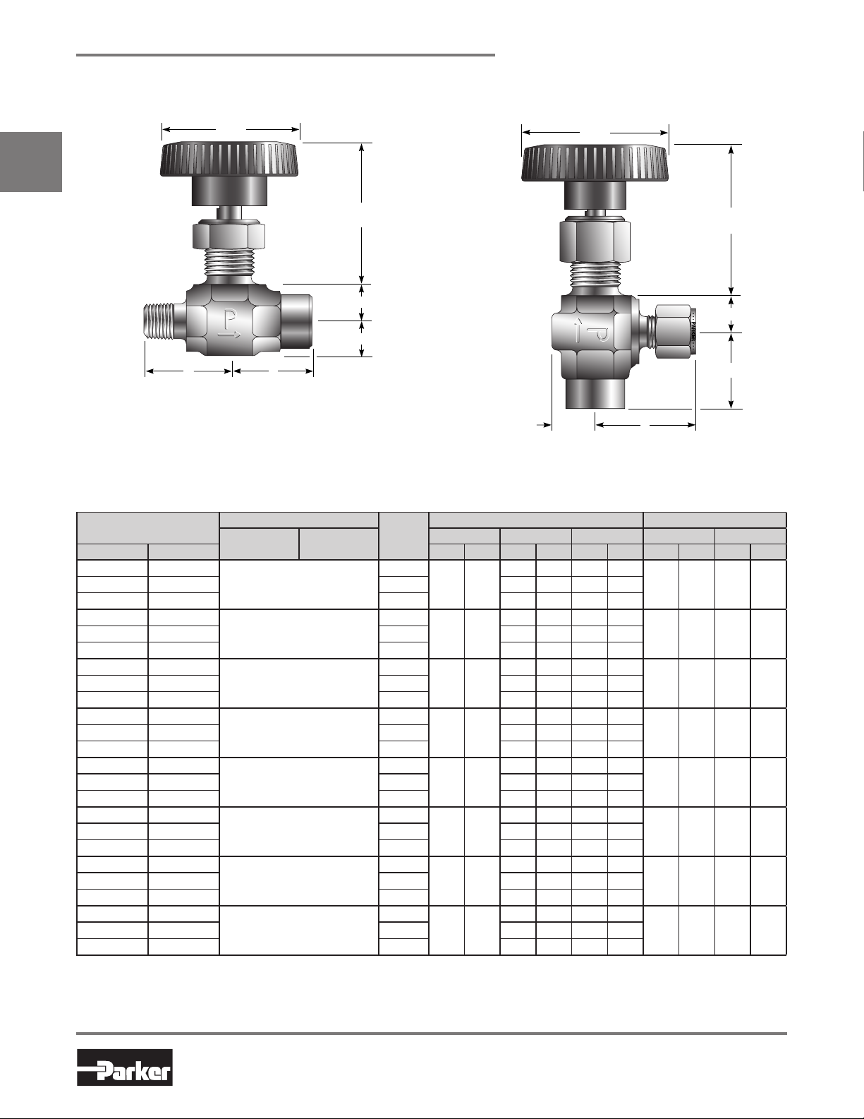
V6 Series Dimensions / Flow Data
Catalog 4110-NV
*
V
Panel Hole Diameter:
0.45 (11.4)
Max Panel Thickness:
0.25 (6.4)
Model Shown:
6M4F-V6LR-V-SS
* Note: Handle diameter for K Stem V6 Series Valves is 1.38 (35.4)
( ) Denotes dimensions in millimeters
Basic
Part Number
Inline Angle Inch mm C
4F-V6LR 4F-V6AR
End Connections
Inlet
(Port 1)
1/4" Female NPT
Outlet
(Port 2)
Stem
Type
Blunt
Orifice Inline Angle A† B†
0.228 5.8
4F-V6LK 4F-V6AK PCTFE 0.80 0.87 1.23 0.56
6A-V6LR 6A-V6AR
3/8" Compression A-LOK
Blunt
®
0.228 5.8
6A-V6LK 6A-V6AK PCTFE 0.80 0.87 1.23 0.56
6M-V6LR 6M-V6AR
3/8" Male NPT
Blunt
0.228 5.8
6M-V6LK 6M-V6AK PCTFE 0.80 0.87 1.23 0.56
6Z-V6LR 6Z-V6AR
3/8" Compression CPI™
Blunt
0.228 5.8
6Z-V6LK 6Z-V6AK PCTFE 0.80 0.87 1.23 0.56
8A-V6LR 8A-V6AR
8A-V6LK 8A-V6AK PCTFE 0.80 0.87 1.23 0.56
8Z-V6LR 8Z-V6AR
1/2" Compression A-LOK
1/2" Compression CPI™
Blunt
®
0.228 5.8
Blunt
0.228 5.8
8Z-V6LK 8Z-V6AK PCTFE 0.80 0.87 1.23 0.56
M10A-V6LR M10A-V6AR
10mm Compression A-LOK
M10A-V6LK M10A-V6AK PCTFE 0.80 0.87 1.23 0.56
M10Z-V6LR M10Z-V6AR
10mm Compression CPI™
Blunt
®
0.228 5.8
Blunt
0.228 5.8
M10Z-V6LK M10Z-V6AK PCTFE 0.80 0.87 1.23 0.56
* Tested in accordance with ISA S75.02. Gas flow will be choked when P1 - P2 / P1 = XT.
† For CPI™ and A-LOK®, dimensions are measured with nuts in the finger tight position.
Flow Data Dimensions
* CVXT* Inch mm Inch mm
VXT
0.73 0.90 1.23 0.50
0.73 0.90 1.23 0.50
0.73 0.90 1.23 0.50
0.73 0.90 1.23 0.50
0.73 0.90 1.23 0.50
0.73 0.90 1.23 0.50
0.73 0.90 1.23 0.50
0.73 0.90 1.23 0.50
*
Model Shown:
4F6Z-V6AK-SS
0.94 23.9 0.94 23.94F-V6LN 4F-V6AN Needle 0.55 0.61 0.92 0.62
1.29 32.8 1.29 32.86A-V6LN 6A-V6AN Needle 0.55 0.61 0.92 0.62
1.03 26.2 1.03 26.26M-V6LN 6M-V6AN Needle 0.55 0.61 0.92 0.62
1.29 32.8 1.29 32.86Z-V6LN 6Z-V6AN Needle 0.55 0.61 0.92 0.62
1.40 35.6 1.40 35.68A-V6LN 8A-V6AN Needle 0.55 0.61 0.92 0.62
1.40 35.6 1.40 35.68Z-V6LN 8Z-V6AN Needle 0.55 0.61 0.92 0.62
1.30 33.0 1.30 33.0M10A-V6LN M10A-V6AN Needle 0.55 0.61 0.92 0.62
1.30 33.0 1.30 33.0M10Z-V6LN M10Z-V6AN Needle 0.55 0.61 0.92 0.62
Dimensions in inches/millimeters are
for reference only, subject to change.
6
Parker Hannifin Corporation
Instrumentation Products Division
Jacksonville, AL USA
http://www.parker.com/ipdus
Catalog 4110-NV
B
Max Open 3.01 (76.5)
Min Close 2.23 (56.6)
A
.58 (14.7)
2.75
(69.9)
.59
(15.0)
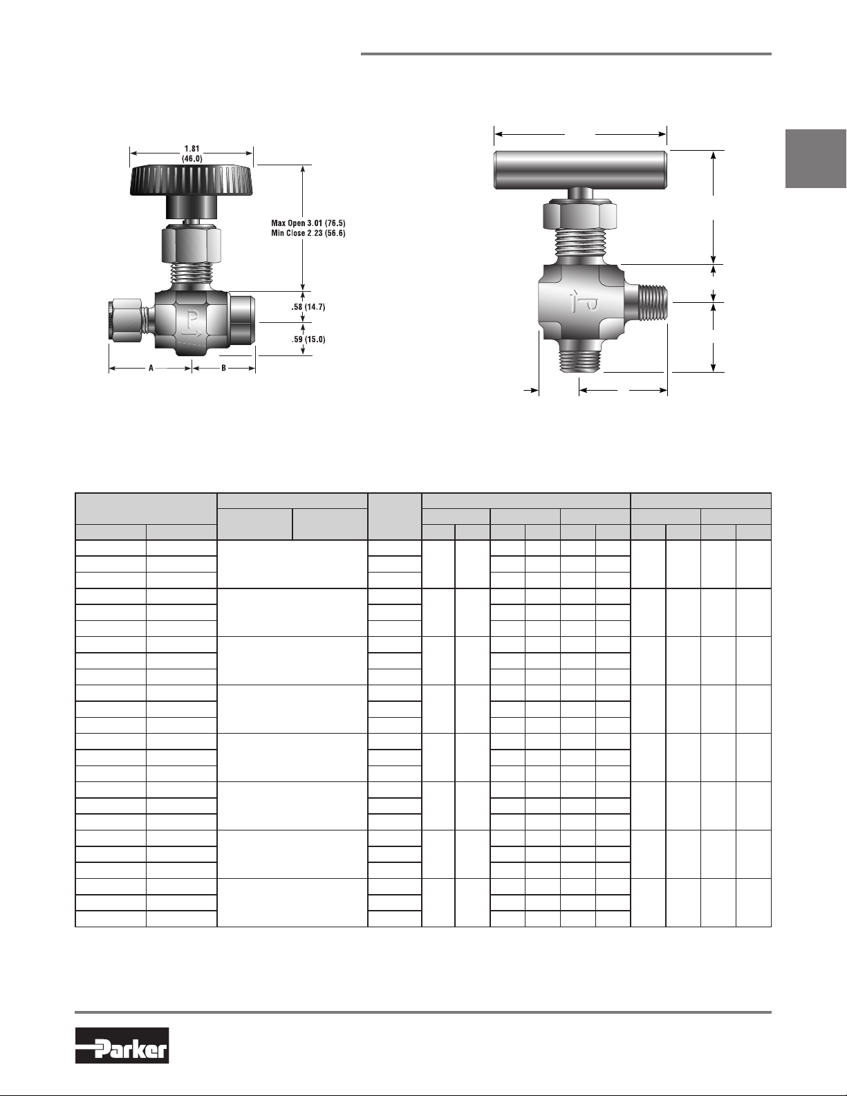
V8 Series Dimensions / Flow Data
*
Model Shown:
8Z6F-V8LK-SS
* Note: Handles for N or R Stem V8 Series Valves are a T-bar
( ) Denotes dimensions in millimeters
Panel Hole Diameter:
0.77 (19.6)
Max Panel Thickness:
0.40 (10.2)
V Series Needle Valves
*
V
Model Shown:
8M-V8AN-EPR-SS
Basic
Part Number
Inline Angle Inch mm CVXT* CVXT* Inch mm Inch mm
6F-V8LR 6F-V8AR
End Connections
Inlet
(Port 1)
3/8" Female NPT
Outlet
(Port 2)
Stem
Type
Blunt
Orifice Inline Angle A† B†
0.312 7.9
Flow Data Dimensions
1.23 0.87 1.66 0.72
1.34 34.0 1.34 34.06F-V8LN 6F-V8AN Needle 1.05 0.83 1.28 0.80
6F-V8LK 6F-V8AK PCTFE 1.29 0.91 1.90 0.76
8A-V8LR 8A-V8AR
1/2" Compression A-LOK
Blunt
®
0.312 7.9
1.23 0.87 1.66 0.72
1.53 38.9 1.53 38.98A-V8LN 8A-V8AN Needle 1.05 0.83 1.28 0.80
8A-V8LK 8A-V8AK PCTFE 1.29 0.91 1.90 0.76
8M-V8LR 8M-V8AR
1/2" Male NPT
Blunt
0.312 7.9
1.23 0.87 1.66 0.72
1.34 34.0 1.34 34.08M-V8LN 8M-V8AN Needle 1.05 0.83 1.28 0.80
8M-V8LK 8M-V8AK PCTFE 1.29 0.91 1.90 0.76
8Z-V8LR 8Z-V8AR
1/2" Compression CPI™
Blunt
0.312 7.9
1.23 0.87 1.66 0.72
1.53 38.9 1.53 38.98Z-V8LN 8Z-V8AN Needle 1.05 0.83 1.28 0.80
8Z-V8LK 8Z-V8AK PCTFE 1.29 0.91 1.90 0.76
M10A-V8LR M10A-V8AR
10mm Compression A-LOK
Blunt
®
0.281 7.1
1.13 0.79 1.52 0.66
1.42 36.1 1.42 36.1M10A-V8LN M10A-V8AN Needle 0.97 0.78 1.18 0.75
M10A-V8LK M10A-V8AK PCTFE 1.18 0.80 1.69 0.66
M10Z-V8LR M10Z-V8AR
M10Z-V8LK M10Z-V8AK PCTFE 1.18 0.80 1.69 0.66
M12A-V8LR M12A-V8AR
10mm Compression CPI™
12mm Compression A-LOK
Blunt
0.281 7.1
Blunt
®
0.281 7.1
1.13 0.79 1.52 0.66
1.42 36.1 1.42 36.1M10Z-V8LN M10Z-V8AN Needle 0.97 0.78 1.18 0.75
1.13 0.79 1.52 0.66
1.51 38.4 1.51 38.4M12A-V8LN M12A-V8AN Needle 0.97 0.78 1.18 0.75
M12A-V8LK M12A-V8AK PCTFE 1.18 0.80 1.69 0.66
M12Z-V8LR M12Z-V8AR
12mm Compression CPI™
Blunt
0.281 7.1
1.13 0.79 1.52 0.66
1.51 38.4 1.51 38.4M12Z-V8LN M12Z-V8AN Needle 0.97 0.78 1.18 0.75
M12Z-V8LK M12Z-V8AK PCTFE 1.18 0.80 1.69 0.66
* Tested in accordance with ISA S75.02. Gas flow will be choked when P1 - P2 / P1 = XT.
† For CPI™ and A-LOK®, dimensions are measured with nuts in the finger tight position.
Dimensions in inches/millimeters are
for reference only, subject to change.
7
Parker Hannifin Corporation
Instrumentation Products Division
Jacksonville, AL USA
http://www.parker.com/ipdus

V Series Needle Valves
B
A
Max Open 3.01 (76.5)
Min Close 2.23 (56.6)
.61 (15.5)
.64 (16.3)
2.75
(69.9)
B
Max Open 3.01 (76.5)
Min Close 2.23 (56.6)
A
.64 (16.3)
1.81
(46.0)
.61
(15.5)
V12 Series Dimensions / Flow Data
*
V
Model Shown: 10Z-V12LN-B
* Note: Handles for N or R Stem V12 Series Valves are a T-bar
( ) Denotes dimensions in millimeters
Panel Hole Diameter:
0.77 (19.6)
Max Panel Thickness:
0.40 (10.2)
Catalog 4110-NV
*
Model Shown:
8M8F-V12AK-BN-SS
Basic
Part Number
Inline Angle Inch mm C
8F-V12LR 8F-V12AR
End Connections
Inlet
(Port 1)
1/2" Female NPT
Outlet
(Port 2)
Stem
Type
Blunt
Orifice Inline Angle A† B†
0.312 7.9
Flow Data Dimensions
XT* C
V
V
1.23 0.87 1.66 0.72
8F-V12LK 8F-V12AK PCTFE 1.29 0.91 1.90 0.76
8W-V12LR 8W-V12AR
1/2" Tube Socket Weld
Blunt
1.23 0.87 1.66 0.72
0.312 7.9
8W-V12LK 8W-V12AK PCTFE 1.29 0.91 1.90 0.76
10A-V12LR 10A-V12AR
5/8" Compression A-LOK
Blunt
®
0.312 7.9
1.23 0.87 1.66 0.72
10A-V12LK 10A-V12AK PCTFE 1.29 0.91 1.90 0.76
10Z-V12LR 10Z-V12AR
5/8" Compression CPI
Blunt
™
0.312 7.9
1.23 0.87 1.66 0.72
10Z-V12LK 10Z-V12AK PCTFE 1.29 0.91 1.90 0.76
12A-V12LR 12A-V12AR
3/4" Compression A-LOK
Blunt
®
0.312 7.9
1.23 0.87 1.66 0.72
12A-V12LK 12A-V12AK PCTFE 1.29 0.91 1.90 0.76
12Z-V12LR 12Z-V12AR
3/4" Compression CPI
Blunt
™
0.312 7.9
1.23 0.87 1.66 0.72
12Z-V12LK 12Z-V12AK PCTFE 1.29 0.91 1.90 0.76
* Tested in accordance with ISA S75.02. Gas flow will be choked when P1 - P2 / P1 = XT.
† For CPI™ and A-LOK®, dimensions are measured with nuts in the finger tight position.
XT* Inch mm Inch mm
1.38 35.1 1.38 35.18F-V12LN 8F-V12AN Needle 1.05 0.83 1.28 0.80
1.12 28.4 1.12 28.48W-V12LN 8W-V12AN Needle 1.05 0.83 1.28 0.80
1.52 38.6 1.52 38.610A-V12LN 10A-V12AN Needle 1.05 0.83 1.28 0.80
1.52 38.6 1.52 38.610Z-V12LN 10Z-V12AN Needle 1.05 0.83 1.28 0.80
1.52 38.6 1.52 38.612A-V12LN 12A-V12AN Needle 1.05 0.83 1.28 0.80
1.52 38.6 1.52 38.612Z-V12LN 12Z-V12AN Needle 1.05 0.83 1.28 0.80
Dimensions in inches/millimeters are
for reference only, subject to change.
8
Parker Hannifin Corporation
Instrumentation Products Division
Jacksonville, AL USA
http://www.parker.com/ipdus
Catalog 4110-NV
V Series Needle Valves
How to Order
Dimensions in inches/millimeters are for reference only, subject to change.
The correct part number is easily derived from the following example and ordering chart. The six product
characteristics required are coded as shown in the chart.
Example 1, below, describes an angle pattern V4 Series needle valve equipped with 1/4" CPI™ compression inlet
and outlet ports, a PCTFE tipped stem, Nitrile seals, and stainless steel construction.
Example 2, below, describes an inline pattern V6 Series needle valve equipped with 1/4" male NPT inlet port, 1/4"
female NPT outlet port, a needle stem type, PTFE stem seal, brass construction.
Example 1: 4Z-V4AK-BN-SS (shown in the part number blocks below)
Example 2: 4M4F-V6LN-B
V
4Z
Inlet
Port*
Inlet
Port*
2A 2M 4A
2F 2Z 4Z
2A 4A 6A M6A
2F 4M 6Z M6Z
2M 4W M3A M8A
2Z 4Z M3Z M8Z
4A 6A 8A M10A
4F 6M 8Z M10Z
4M 6W M8A M12A
4Z 6Z M8Z M12Z
4F 6Z 8Z M12A
6A 8A M10A M12Z
6F 8M M10Z
8F 10A 12A
8W 10Z 12Z
Outlet
Port*
Outlet
Port*
*If the inlet and outlet ports are the same, eliminate the outlet port designator.
How to Order Options
Valve
Series
Valve
Series
V2
V4
V6
V8
V12
V4
Stem
Type
R Blunt (30°)
N Needle (2-1/2°)
K PCTFE
AK
Stem
Type
BN SS
Stem
Seal
Stem
Seal
Blank PTFE
BN Nitrile Rubber
EPR Ethylene
Propylene
Rubber
V Fluorocarbon
Rubber
–– –
Body
Material
Body
Material
SS Stainless Steel
S Steel
M Monel® Alloy 400
B Brass
Colored Round Handles – Add the designator corresponding to the correct handle color as a suffix to the part
number. Black is standard, W - white, B - blue, G - green, R - red, Y - yellow. Example: M10A-V6LK-SS-G
Oxygen Cleaning – Add the suffix -C3 to the end of the part number to receive valves cleaned and assembled for
oxygen service in accordance with Parker Specification ES8003. Example: 4A-V4AN-EPR-SS-C3
9
Parker Hannifin Corporation
Instrumentation Products Division
Jacksonville, AL USA
http://www.parker.com/ipdus

V Series Needle Valves
Catalog 4110-NV
How to Order Components
Colored Round Nylon Handles with Handle Screw – Valve Series-Handle-Color. Example: V4-HANDLE-BLUE
Stainless Steel T-Bar Handles with Handle Screw – Examples: V2: V2-BAR-HANDLE-SS;
V4: V4-BAR-HANDLE-SS; V6: V6-BAR-HANDLE-SS; V8: U12-BAR-HANDLE-SS; V12: U12-BAR-HANDLE-SS
V
Aluminum T-Bar Handles with Handle Screw – Examples: V2: Not available; V4: V4-BAR-HANDLE-AL;
V6: V4-BAR-HANDLE-AL; V8: U12-BAR-HANDLE-AL; V12: U12-BAR-HANDLE-AL
Panel Mounting Nuts – Examples: V2: 2-Panel-Nut-SS; V4: 4-Panel-Nut-SS; V6: 6-Panel-Nut-SS;
V8: 8-Panel-Nut-SS
How to Order Maintenance Kits
PTFE Packing Stem Kits – Consists of One Stem; One PTFE Packing; One Upper Packing Washer; One Lower
Packing Washer; One Packing Nut; Maintenance Instructions.
Kit-Valve Series and StemType-Body Material. Examples: KIT-V4K-SS; KIT-V6N-B
Fluorocarbon Rubber Packing Stem Kits – Consists of One Stem; One Fluorocarbon Rubber O-ring Seal;
One O-ring Back-up Gland; One O-ring Gland; One Lower Packing Washer; One Packing Nut; Maintenance
Instructions.
Kit-Valve Series and Stem Type-V-Body Material. Examples: KIT-V2R-V-B; KIT-V4K-V-SS
Nitrile Rubber Packing Stem Kits – Consists of One Stem; One Nitrile Rubber O-ring Seal; One O-ring
Back-up Gland; One O-ring Gland; One Lower Packing Washer; One Packing Nut; Maintenance Instructions.
Kit-Valve Series and Stem Type-BN-Body Material. Examples: KIT-V2R-BN-B; KIT-V4K-BN-SS
Ethylene Propylene Rubber Packing Stem Kits – Consists of One Stem; One Ethylene Propylene Rubber
O-ring Seal; One O-ring Back-up Gland; One O-ring Gland; One Lower Packing Washer; One Packing Nut;
Maintenance Instructions.
Kit-Valve Series and Stem Type-EPR-Body Material. Examples: KIT-V2R-EPR-B; KIT-V4K-EPR-SS
10
Parker Hannifin Corporation
Instrumentation Products Division
Jacksonville, AL USA
http://www.parker.com/ipdus
Catalog 4110-NV
Notes
V
11
Parker Hannifin Corporation
Instrumentation Products Division
Jacksonville, AL USA
http://www.parker.com/ipdus
U Series Needle Valves
Catalog 4110-NV
Introduction
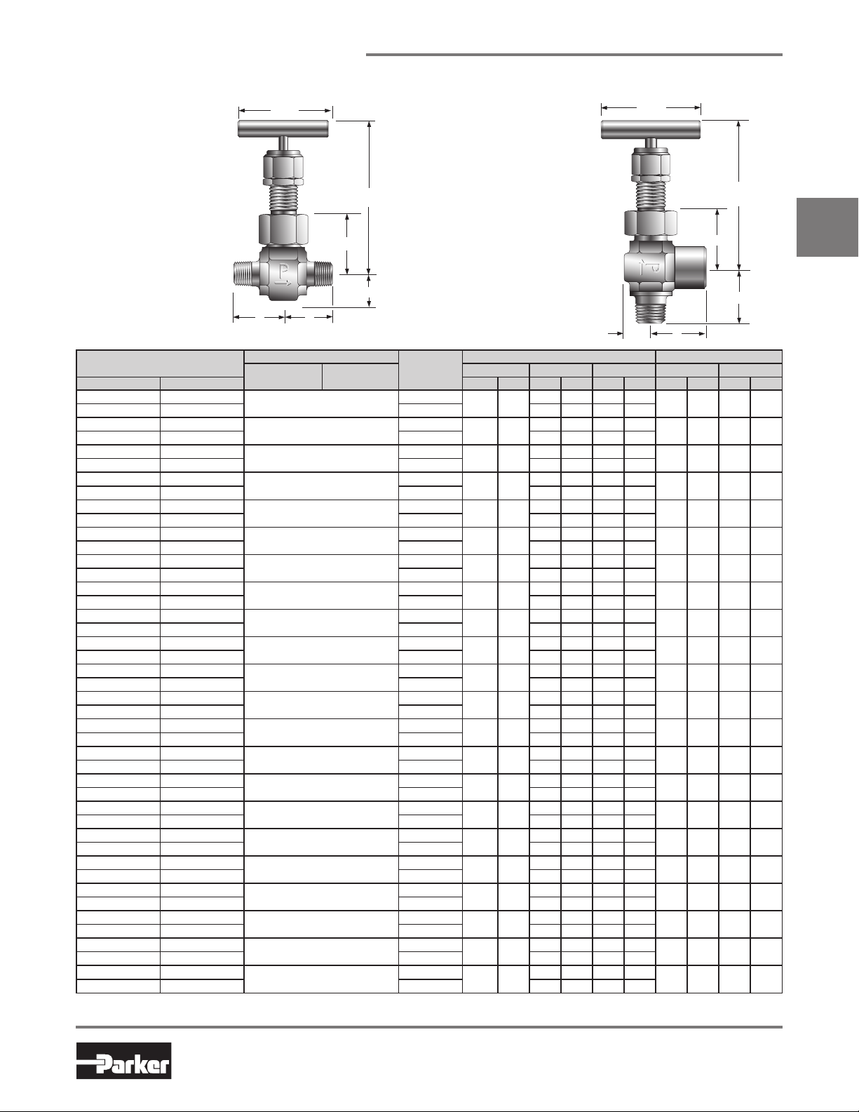
Parker U Series Union Bonnet Valves have been engineered for use at pressures up to 6,000 (414 bar) and
temperatures as high as 1,200°F (649°C). A non-rotating lower stem helps to extend packing life by removing
rotation from the packing area. Stem packing below the threads isolates the thread lubricant from the flow,
ensuring adequate lubrication regardless of the media.
Features
Union bonnet design ensures high integrity seal under
U
severe service applications
Packing below the power threads protects thread
lubricants from media and isolates the lubricants from
the media
Dust seal in the packing nut protects stem threads
from external contamination
Stem swivel above the packing eliminates entrapment
area and increases packing life
Choice of Grafoil® or PTFE packing
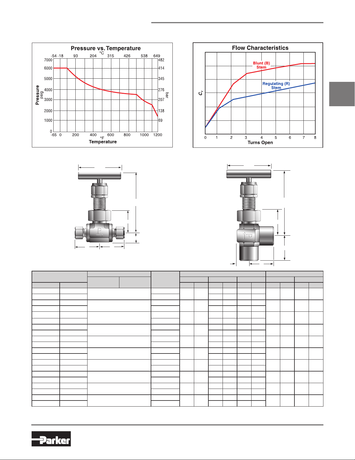
Choice of Regulating or Blunt stem types. Blunt stem
type helps combat wire draw which may occur when
two phase flow is present (i.e. steam service)
316 stainless steel construction
Wide variety of US Customary and SI ports
Panel mountable
100% factory tested
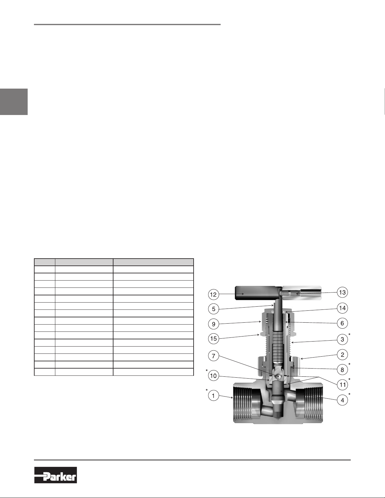
Materials of Construction
Item # Description Material
*1 Body ASTM A 182, Type F316
2 Bonnet Nut ASTM A 479, Type 316
*3 Bonnet ASTM A 479, Type 316
*4 Lower Stem* ASTM A 564, Type 630
5 Upper Stem ASTM A 564, Type 630
6 Stem Guide ASTM A 581, Type 416
7 Ball 440-C Stainless Steel
*8 Bonnet Seal** Nickel-Chromium-Iron Alloy
9 Packing Nut ASTM A 479, Type 316
*10 Packing*** Grafoil
*11 Packing Washer 316 Stainless Steel
12 Handle**** Aluminum
13 Handle Screw 316 Stainless Steel
14 Dust Seal***** Nylon 6/6
15 Locking Nut Stainless Steel
* Wetted parts
* Lower Stem material is ASTM A 276 Type 316 with HT option
** Not required on U6 and U12 Series which have metal-to-metal seals
*** Optional PTFE Packing is available
**** Handle material is stainless steel with HT option
***** Dust Seal not available with HT option
Lubrication: Molybdenum disulfide with soft metallic fillers
®
Specifications
Pressure Rating:
6000 psig (414 bar) CWP
Temperature Rating:
PTFE packing:
-65°F to 450°F (-54°C to 232°C)
Grafoil® packing:
-65°F to 700°F (-54°C to 371°C)
Grafoil® packing with HT option:
-65°F to 1200°F (-54°C to 649°C)
Orifice: .177" to .437" (4.5mm to 11.1mm)
: .53 to 3.55
C
V
Pressure Rating and Tubing Selection:
For working pressures of A-LOK® and CPI™ tube
connections, please see the Instrument Tubing
Selection Guide (Bulletin 4200-TS), found in the
Technical Section of the Parker Instrumentation
Products Master Binder, or the Parker Instrument
Tube Fitting Installation Manual (Bulletin 4200-B4).
For working pressures of valves with external or
internal pipe threads, please see Catalog 4260,
Instrumentation Pipe Fittings.
Grafoil® is a registered trademark GrafTech International Holdings, Inc.
12
Model Shown: 16F-U16LR-G-SS
Parker Hannifin Corporation
Instrumentation Products Division
Jacksonville, AL USA
http://www.parker.com/ipdus
Catalog 4110-NV
U Series Needle Valves
Pressure vs. Temperature
U6 Series Dimensions / Flow Data
2.00
(50.8)
Model Shown:
4Z-U6LB-T-SS
Max Open 3.98 (101.1)
Min Close 3.43 (87.1)
Flow Characteristics
Panel Hole Diameter:
0.65 (16.5)
Max Panel Thickness:
0.42 (10.7)
2.00
(50.8)
Max Open 3.98 (101.1)
Min Close 3.43 (87.1)
U
1.34 (34.0)
.59 (15.0)
A
Basic
Part Number
Inline Angle Inch mm C
2F-U6LR 2F-U6AR
2F-U6LB 2F-U6AB Blunt 0.69 0.50 0.91 0.42
4A-U6LR 4A-U6AR
4A-U6LB 4A-U6AB Blunt 0.65 0.48 0.86 0.40
4F-U6LR 4F-U6AR
4F-U6LB 4F-U6AB Blunt 0.82 0.59 1.09 0.50
4M-U6LR 4M-U6AR
4M-U6LB 4M-U6AB Blunt 0.65 0.48 0.86 0.40
4W-U6LR 4W-U6AR
4W-U6LB 4W-U6AB Blunt 0.65 0.48 0.86 0.40
4Z-U6LR 4Z-U6AR
4Z-U6LB 4Z-U6AB Blunt 0.65 0.48 0.86 0.40
M6A-U6LR M6A-U6AR
M6A-U6LB M6A-U6AB Blunt 0.65 0.48 0.86 0.40
M6Z-U6LR M6Z-U6AR
M6Z-U6LB M6Z-U6AB Blunt 0.65 0.48 0.86 0.40
M8A-U6LR M8A-U6AR
M8A-U6LB M8A-U6AB Blunt 0.65 0.48 0.86 0.40
M8Z-U6LR M8Z-U6AR
M8Z-U6LB M8Z-U6AB Blunt 0.65 0.48 0.86 0.40
B
End Connections
Inlet
(Port 1)
Outlet
(Port 2)
1/8" Female NPT
1/4" Compression A-LOK
1/4" Female NPT
1/4" Male NPT
1/4" Socket Weld
1/4" Compression CPI™
6mm Compression A-LOK
6mm Compression CPI™
8mm Compression A-LOK
8mm Compression CPI™
®
( ) Denotes dimensions
in millimeters
Stem
Type
Regulating
Regulating
Regulating
Regulating
Regulating
Regulating
Regulating
®
Regulating
Regulating
®
Regulating
* Tested in accordance with ISA S75.02. Gas flow will be choked when P
† For CPI™ and A-LOK®, dimensions are measured with nuts in the finger tight position.
4F-U6AR-T-SS
.59
(15.0)
Orifice Inline Angle A† B†
0.188 4.8
0.177 4.5
0.228 5.8
0.177 4.5
0.177 4.5
0.177 4.5
0.177 4.5
0.177 4.5
0.177 4.5
0.177 4.5
- P2 / P1 = XT.
1
Flow Data Dimensions
* CVXT* Inch mm Inch mm
VXT
0.58 0.83 0.77 0.70
0.53 0.80 0.70 0.67
0.78 0.95 1.04 0.80
0.53 0.80 0.70 0.67
0.53 0.80 0.70 0.67
0.53 0.80 0.70 0.67
0.53 0.80 0.70 0.67
0.53 0.80 0.70 0.67
0.53 0.80 0.70 0.67
0.53 0.80 0.70 0.67
Model Shown:
1.34 (34.0)
A
B
1.00 25.4 1.00 25.4
1.38 35.1 1.38 35.1
1.03 26.2 1.03 26.2
1.09 27.7 1.09 27.7
.91 23.1 .91 23.1
1.38 35.1 1.38 35.1
1.38 35.1 1.38 35.1
1.38 35.1 1.38 35.1
1.38 35.1 1.38 35.1
1.38 35.1 1.38 35.1
Dimensions in inches/millimeters are
for reference only, subject to change.
13
Parker Hannifin Corporation
Instrumentation Products Division
Jacksonville, AL USA
http://www.parker.com/ipdus
U Series Needle Valves
Catalog 4110-NV
U12 Series Dimensions / Flow Data
2.75
(69.9)
Model Shown:
6F-U12LB-G-SS-HT
U
A
( ) Denotes dimensions in millimeters
Basic
Part Number
Inline Angle Inch mm C
4A-U12LR 4A-U12AR
4A-U12LB 4A-U12AB Blunt 0.51 0.40 0.68 0.33
4F-U12LR 4F-U12AR
4F-U12LB 4F-U12AB Blunt 1.03 0.60 1.37 0.51
4Z-U12LR 4Z-U12AR
4Z-U12LB 4Z-U12AB Blunt 0.51 0.40 0.68 0.33
6A-U12LR 6A-U12AR
6A-U12LB 6A-U12AB Blunt 0.77 0.50 1.02 0.42
6F-U12LR 6F-U12AR
6F-U12LB 6F-U12AB Blunt 1.31 0.80 1.74 0.68
6W-U12LR 6W-U12AR
6W-U12LB 6W-U12AB Blunt 0.94 0.57 1.25 0.48
6Z-U12LR 6Z-U12AR
6Z-U12LB 6Z-U12AB Blunt 0.77 0.50 1.02 0.42
8A-U12LR 8A-U12AR
8A-U12LB 8A-U12AB Blunt 1.03 0.60 1.37 0.51
8F-U12LR 8F-U12AR
8F-U12LB 8F-U12AB Blunt 1.31 0.80 1.74 0.68
8W-U12LR 8W-U12AR
8W-U12LB 8W-U12AB Blunt 1.31 0.80 1.74 0.68
8Z-U12LR 8Z-U12AR
8Z-U12LB 8Z-U12AB Blunt 1.03 0.60 1.37 0.51
M10A-U12LR M10A-U12AR
M10A-U12LB M10A-U12AB Blunt 1.03 0.60 1.37 0.51
M10Z-U12LR M10Z-U12AR
M10Z-U12LB M10Z-U12AB Blunt 1.03 0.60 1.37 0.51
M12A-U12LR M12A-U12AR
M12A-U12LB M12A-U12AB Blunt 1.31 0.80 1.74 0.68
M12Z-U12LR M12Z-U12AR
M12Z-U12LB M12Z-U12AB Blunt 1.31 0.80 1.74 0.68
M14A-U12LR M14A-U12AR
M14A-U12LB M14A-U12AB Blunt 1.31 0.80 1.74 0.68
M14Z-U12LR M14Z-U12AR
M14Z-U12LB M14Z-U12AB Blunt 1.31 0.80 1.74
* Tested in accordance with ISA S75.02. Gas flow will be choked when P1 - P2 / P1 = XT.
† For CPI™ and A-LOK®, dimensions are measured with nuts in the finger tight position.
End Connections
Inlet
(Port 1)
1/4" Compression A-LOK
1/4" Female NPT
1/4" Compression CPI™
3/8" Compression A-LOK
3/8" Female NPT
3/8" Tube Socket Weld
3/8" Compression CPI™
1/2" Compression A-LOK
1/2" Female NPT
1/2" Tube Socket Weld
1/2" Compression CPI™
10mm Compression A-LOK
10mm Compression CPI™
12mm Compression A-LOK
12mm Compression CPI™
14mm Compression A-LOK
14mm Compression CPI™
Max Open 4.24 (107.7)
Min Close 3.90 (99.0)
1.50 (38.1)
.61 (15.5)
B
Outlet
(Port 2)
®
®
®
®
®
®
Panel Hole Diameter:
Max Panel Thickness:
Stem
Type
Regulating
Regulating
Regulating
Regulating
Regulating
Regulating
Regulating
Regulating
Regulating
Regulating
Regulating
Regulating
Regulating
Regulating
Regulating
Regulating
Regulating
0.83 (21.1)
0.61 (15.5)
Model Shown:
8A-U12AB-T-SS
.61
(15.5)
Flow Data Dimensions
Orifice Inline Angle A† B†
* CVXT* Inch mm Inch mm
VXT
0.125 3.2
0.250 6.4
0.125 3.2
0.187 4.7
0.312 7.9
0.228 5.8
0.187 4.7
0.250 6.4
0.312 7.9
0.312 7.9
0.250 6.4
0.250 6.4
0.250 6.4
0.312 7.9
0.312 7.9
0.312 7.9
0.312 7.9
0.44 0.57 0.60 0.49
0.94 0.65 1.25 0.55
0.44 0.57 0.60 0.49
0.69 0.61 0.92 0.52
1.19 0.78 1.58 0.66
0.85 0.64 1.13 0.54
0.69 0.61 0.92 0.52
0.94 0.65 1.25 0.55
1.19 0.78 1.58 0.66
1.19 0.78 1.58 0.66
0.94 0.65 1.25 0.55
0.94 0.65 1.25 0.55
0.94 0.65 1.25 0.55
1.19 0.78 1.58 0.66
1.19 0.78 1.58 0.66
1.19 0.78 1.58 0.66
1.19 0.78 1.58 0.66
2.75
(69.9)
Max Open 4.24 (107.7)
Min Close 3.90 (99.0)
1.50 (38.1)
A
B
1.39 35.3 1.39 35.3
1.13 28.7 1.13 28.7
1.39 35.3 1.39 35.3
1.60 40.6 1.60 40.6
1.30 33.0 1.30 33.0
1.13 28.7 1.13 28.7
1.60 40.6 1.60 40.6
1.49 37.8 1.49 37.8
1.50 38.1 1.50 38.1
1.25 31.8 1.25 31.8
1.49 37.8 1.49 37.8
1.53 38.9 1.53 38.9
1.53 38.9 1.53 38.9
1.70 43.2 1.70 43.2
1.70 43.2 1.70 43.2
1.70 43.2 1.70 43.2
1.70 43.2 1.70 43.2
0.68
Dimensions in inches/millimeters are
for reference only, subject to change.
14
Parker Hannifin Corporation
Instrumentation Products Division
Jacksonville, AL USA
http://www.parker.com/ipdus
Catalog 4110-NV
U Series Needle Valves
U16 Series Dimensions / Flow Data
3.50
(88.9)
Model Shown:
16M-U16LR-G-SS
Max Open 5.00 (127.0)
Min Close 4.70 (119.4)
1.86 (47.2)
( ) Denotes dimensions
in millimeters
.85 (21.6)
A
Basic
Part Number
Inline Angle Inch mm CVXT* CVXT* Inch mm Inch mm
8A-U16LR 8A-U16AR
8A-U16LB 8A-U16AB Blunt 1.90 0.95 2.53 0.81
8F-U16LR 8F-U16AR
8F-U16LB 8F-U16AB Blunt 2.67 0.80 3.55 0.68
8M-U16LR 8M-U16AR
8M-U16LB 8M-U16AB Blunt 2.67 0.80 3.55 0.68
8PSW-U16LR 8PSW-U16AR
8PSW-U16LB 8PSW-U16AB Blunt 2.67 0.80 3.55 0.68
8W-U16LR 8W-U16AR
8W-U16LB 8W-U16AB Blunt 1.90 0.95 2.53 0.81
8Z-U16LR 8Z-U16AR
8Z-U16LB 8Z-U16AB Blunt 1.90 0.95 2.53 0.81
12A-U16LR 12A-U16AR
12A-U16LB 12A-U16AB Blunt 2.67 0.80 3.55 0.68
12F-U16LR 12F-U16AR
12F-U16LB 12F-U16AB Blunt 2.67 0.80 3.55 0.68
12M-U16LR 12M-U16AR
12M-U16LB 12M-U16AB Blunt 2.67 0.80 3.55 0.68
12PSW-U16LR 12PSW-U16AR
12PSW-U16LB 12PSW-U16AB Blunt 2.67 0.80 3.55 0.68
12W-U16LR 12W-U16AR
12W-U16LB 12W-U16AB Blunt 2.67 0.80 3.55 0.68
12Z-U16LR 12Z-U16AR
12Z-U16LB 12Z-U16AB Blunt 2.67 0.80 3.55 0.68
16A-U16LR 16A-U16AR
16A-U16LB 16A-U16AB Blunt 2.67 0.80 3.55 0.68
16F-U16LR 16F-U16AR
16F-U16LB 16F-U16AB Blunt 2.67 0.80 3.55 0.68
16M-U16LR 16M-U16AR
16M-U16LB 16M-U16AB Blunt 2.67 0.80 3.55 0.68
16Z-U16LR 16Z-U16AR
16Z-U16LB 16Z-U16AB Blunt 2.67 0.80 3.55 0.68
M12A-U16LR M12A-U16AR
M12A-U16LB M12A-U16AB Blunt 1.90 0.95 2.53 0.81
M12Z-U16LR
M12Z-U16AR
M12Z-U16LB M12Z-U16AB Blunt 1.90 0.95 2.53 0.81
M20A-U16LR M20A-U16AR
M20A-U16LB M20A-U16AB Blunt 2.67 0.80 3.55 0.68
M20Z-U16LR M20Z-U16AR
M20Z-U16LB M20Z-U16AB Blunt 2.67 0.80 3.55 0.68
M25A-U16LR M25A-U16AR
M25A-U16LB M25A-U16AB Blunt 2.67 0.80 3.55 0.68
M25Z-U16LR M25Z-U16AR
M25Z-U16LB M25Z-U16AB Blunt 2.67 0.80 3.55 0.68
12mm Compression A-LOK
12mm Compression CPI™
20mm Compression A-LOK
20mm Compression CPI™
25mm Compression A-LOK
25mm Compression CPI™
B
End Connections
Inlet
(Port 1)
Outlet
(Port 2)
1/2" Compression A-LOK
1/2" Female NPT
1/2" Male NPT
1/2" Pipe Socket Weld
1/2" Tube Socket Weld
1/2" Compression CPI™
3/4" Compression A-LOK
3/4" Female NPT
3/4" Male NPT
3/4" Pipe Socket Weld
3/4" Tube Socket Weld
3/4" Compression CPI™
1" Compression A-LOK
1" Female NPT
1" Male NPT
1" Compression CPI™
®
®
®
®
®
®
* Tested in accordance with ISA S75.02. Gas flow will be choked when P
Panel Hole Diameter:
1.02 (25.9)
Max Panel Thickness:
0.62 (15.7)
Model Shown:
16M16F-U16AB-T-SS
Stem
Type
Regulating
Regulating
Regulating
Regulating
Regulating
Regulating
Regulating
Regulating
Regulating
Regulating
Regulating
Regulating
Regulating
Regulating
Regulating
Regulating
Regulating
Regulating
Regulating
Regulating
Regulating
Regulating
Orifice Inline Angle A† B†
0.394 10.0
0.437 11.1
0.437 11.1
0.437 11.1
0.394 10.0
0.394 10.0
0.437 11.1
0.437 11.1
0.437 11.1
0.437 11.1
0.437 11.1
0.437 11.1
0.437 11.1
0.437 11.1
0.437 11.1
0.437 11.1
0.394 10.0
0.394 10.0
0.437 11.1
0.437 11.1
0.437 11.1
0.437 11.1
- P2 / P1 = XT.
1
.85
(21.6)
Flow Data Dimensions
1.59 0.73 2.11 0.62
1.82 0.72 2.42 0.61
1.82 0.72 2.42 0.61
1.82 0.72 2.42 0.61
1.59 0.73 2.11 0.62
1.59 0.73 2.11 0.62
1.82 0.72 2.42 0.61
1.82 0.72 2.42 0.61
1.82 0.72 2.42 0.61
1.82 0.72 2.42 0.61
1.82 0.72 2.42 0.61
1.82 0.72 2.42 0.61
1.82 0.72 2.42 0.61
1.82 0.72 2.42 0.61
1.82 0.72 2.42 0.61
1.82 0.72 2.42 0.61
1.59 0.73 2.11 0.62
1.59 0.73 2.11 0.62
1.82 0.72 2.42 0.61
1.82 0.72 2.42 0.61
1.82 0.72 2.42 0.61
1.82 0.72 2.42 0.61
† For CPI™ and A-LOK®, dimensions are measured with nuts in the finger tight position.
3.50
(88.9)
Max Open 5.00 (127.0)
Min Close 4.70 (119.4)
1.86 (47.2)
B
1.97 50.0 1.97 50.0
1.56 39.6 1.56 39.6
1.92 48.8 1.92 48.8
1.56 39.6 1.56 39.6
1.69 42.9 1.69 42.9
1.97 50.0 1.97 50.0
1.97 50.0 1.97 50.0
1.63 41.4 1.63 41.4
1.63 41.4 1.63 41.4
1.56 39.6 1.56 39.6
1.56 39.6 1.56 39.6
1.97 50.0 1.97 50.0
1.97 50.0 1.97 50.0
1.81 46.0 1.81 46.0
1.81 46.0 1.81 46.0
1.97 50.0 1.97 50.0
1.97 50.0 1.97 50.0
1.97 50.0 1.97 50.0
1.97 50.0 1.97 50.0
1.97 50.0 1.97 50.0
1.97 50.0 1.97 50.0
1.97 50.0 1.97 50.0
Dimensions in inches/millimeters are
for reference only, subject to change.
U
A
15
Parker Hannifin Corporation
Instrumentation Products Division
Jacksonville, AL USA
http://www.parker.com/ipdus
 Loading...