

Parker Hannifin Instrument Tube Fitting Installation Manual
Instrument Tube Fitting
Installation Manual
Bulletin 4200-B4 May 2014

Table of Contents
Installation
Installation Valves Fittings Tubing
Tubing Fitting Installation
Tubing vs Pipe ............................................................ 1
Principles of Tube Line Fabrication
Instrument Tubing Selection Guide........................... 19
Tubing Preparation
(handling, cutting, deburring, cleaning)
Assembly & Remake
Parker IPD Ferrule Presetting Tool
MPI™ Assembly & Remake
MPI™ Preset Tools
MPI™ Tubing Selection
Dielectric Fittings
High Integrity Coupling Assembly
Installation of Weld Fittings
Analytical Tube Fittings
Heat Code Traceability
Parker Suparcase
Thread Identification
Thread and Tube End Size Charts
Pipe Data and Dimensions
............................. 3
.................... 29
................................................ 32
........................... 37
..................................... 41
................................................... 42
............................................ 44
...................................................... 48
............................ 49
....................................... 50
............................................. 56
............................................. 58
®
– Ferrule Hardening ................. 60
................................................. 63
........................... 69
....................................... 77
Bulletin 4200-B4
Offer of Sale
The items described in this document are hereby offered for sale by Parker-Hannifin Corporation, its subsidiaries or its
authorized distributors. This offer and its acceptance are governed by the provisions stated in the detailed “Offer of Sale”
elsewhere in this document or available at www.parker.com/ipdus.
© 2014 Parker Hannifin Corporation. All rights reserved.
ii
Parker Hannifin Corporation
Instrumentation Products Division
Huntsville, AL USA
http://www.parker.com/ipdus
Bulletin 4200-B4
Table of Contents
Parker Valves Overview
Needle Valves ........................................................... 79
Ball Valves
Check Valves
Metering Valves
................................................................ 85
............................................................ 93
...................................................... 105
Parker Fittings Overview
CPI™ / A-LOK® Fittings ........................................... 109
MPI Fittings
Pipe Fittings
Welded Fittings
............................................................. 110
............................................................ 111
....................................................... 112
Parker Tubing Overview ................................... 113
InstallationValvesFittingsTubing
WARNING – USER RESPONSIBILITY
FAILURE OR IMPROPER SELECTION OR IMPROPER USE OF THE PRODUCTS DESCRIBED HEREIN OR
RELATED ITEMS CAN CAUSE DEATH, PERSONAL INJURY AND PROPERTY DAMAGE.
This document and other information from Parker-Hannifin Corporation, its subsidiaries and authorized distributors
provide product or system options for further investigation by users having technical expertise.
The user, through its own analysis and testing, is solely responsible for making the final selection of the system and
components and assuring that all performance, endurance, maintenance, safety and warning requirements of the
application are met. The user must analyze all aspects of the application, follow applicable industry standards, and
follow the information concerning the product in the current product catalog and in any other materials provided from
Parker or its subsidiaries or authorized distributors.
To the extent that Parker or its subsidiaries or authorized distributors provide component or system options based upon
data or specifications provided by the user, the user is responsible for determining that such data and specifications
are suitable and sufficient for all applications and reasonably foreseeable uses of the components or systems.
NOTICE: The information contained within this publication is intended
for educational purposes only. Information contained within is not intended
for re-sale and may not be reproduced in whole or in part without the
express written consent of The Parker Hannifin Corporation.
iii
Parker Hannifin Corporation
Instrumentation Products Division
Huntsville, AL USA
http://www.parker.com/ipdus

Notes
Installation
Bulletin 4200-B4
iv
Parker Hannifin Corporation
Instrumentation Products Division
Huntsville, AL USA
http://www.parker.com/ipdus
Bulletin 4200-B4
Tubing vs. Pipe
Tubing vs. Pipe
Standard fluid line systems, whether for simple household use or for
the more exacting requirements of industry, were for many years
constructed from threaded pipe of assorted materials and were
assembled with various standard pipe fitting shapes, unions and
nipples. Such systems under high pressures were plagued with leakage
problems besides being cumbersome, inefficient and costly to assemble
and maintain. Therefore, the use of pipe in these systems has largely
been replaced by tubing because of the many advantages it offers.
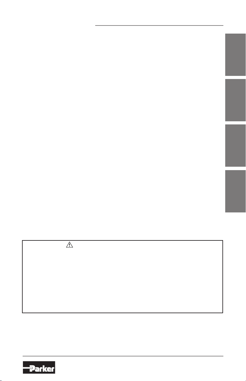
Old Method – Each connection is
threaded – requires numerous fittings
– system not flexible or easy to install
and service connections not smooth
inside – pockets obstruct flow.
Modern Method – Bendable tubing
needs fewer fittings – no threading
required – system light and compact
– easy to install and service – no
internal pockets or obstructions to
Figure 1 Tubing provides simplified,
free flow system.
free flow.
Installation
Major Advantages of Tubing vs. Pipe
1. Bending Quality – Tubing has strong but relatively thin walls; is easy
to bend. Tube fabrication is simple.
2. Greater Strength – Tubing is stronger. No weakened sections from
reduction of wall thickness by threading.
Pipe
Figure 2 With no threading necessary, tubing does not require extra wall
thickness
1
Parker Hannifin Corporation
Instrumentation Products Division
Huntsville, AL USA
http://www.parker.com/ipdus
Tubing

Tubing vs. Pipe
Installation
3. Less Turbulence – Smooth bends result in streamlined flow passage
Bulletin 4200-B4
and less pressure drop.
4. Economy of Space and Weight – With its better bending qualities and
a smaller outside diameter, tubing saves space and permits working
in close quarters. Tube fittings are smaller and also weigh less.
5. Flexibility – Tubing is less rigid, has less tendency to transmit
vibration from one connection to another.
6. Fewer Fittings – Tubing bends substitute for elbows. Fewer fittings
mean fewer joints, fewer leak paths.
7. Tighter Joints – Quality tube fittings, correctly assembled, give better
assurance of leak-free systems.
8. Better Appearance – Tubing permits smoother contours with fewer
fittings for a professional look to tubing systems.
9. Cleaner Fabrication – No sealing compounds on tube connections.
Again no threading; minimum chance of scale, metal chips, foreign
particles in system.
10. Easier Assembly and Disassembly – Every tube connection serves as
a union. Tube connections can be reassembled repeatedly with easy
wrench action.
11. Less Maintenance – Advantages of tubing and tube fittings add up to
dependable, trouble-free installations.
2
Parker Hannifin Corporation
Instrumentation Products Division
Huntsville, AL USA
http://www.parker.com/ipdus
Bulletin 4200-B4
Principles of Tube Line Fabrication
Principles of Tube Line Fabrication
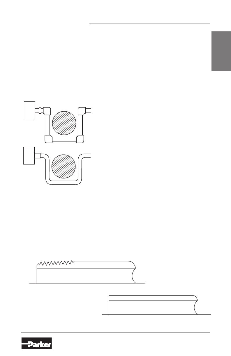
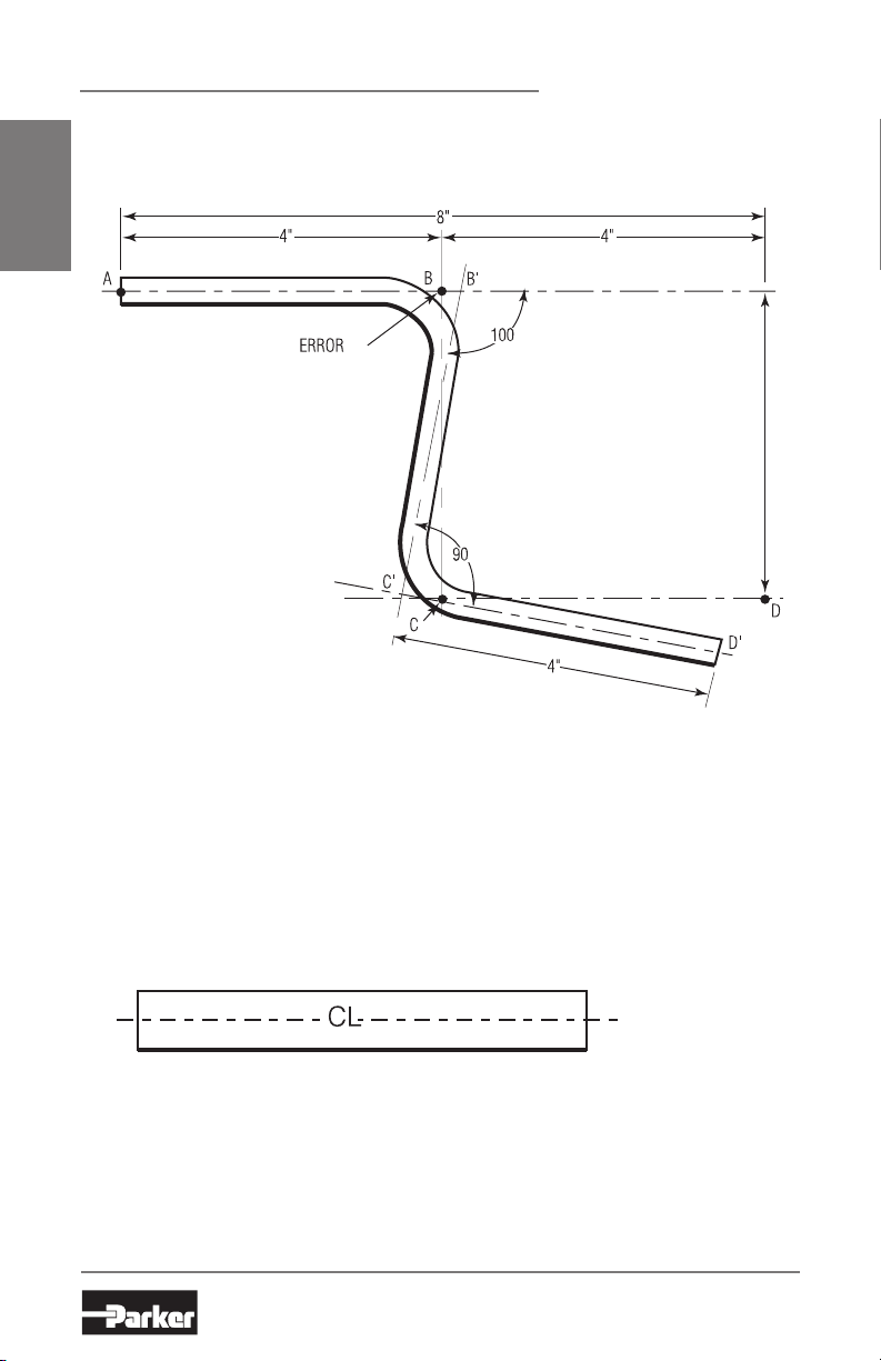
1. Measure Exactly and Bend Accurately
Measuring exactly and bending accurately are the two most important rules which must be observed when fabricating a tube line.
Figure 3 Accurate measurements coupled with exact angles may
result in a tube line that will fit at points (A-D).
Installation
Exact measurement is required to insure that you obtain the desired
distance between bends. If you do not measure exactly, the tube line
will not fit.
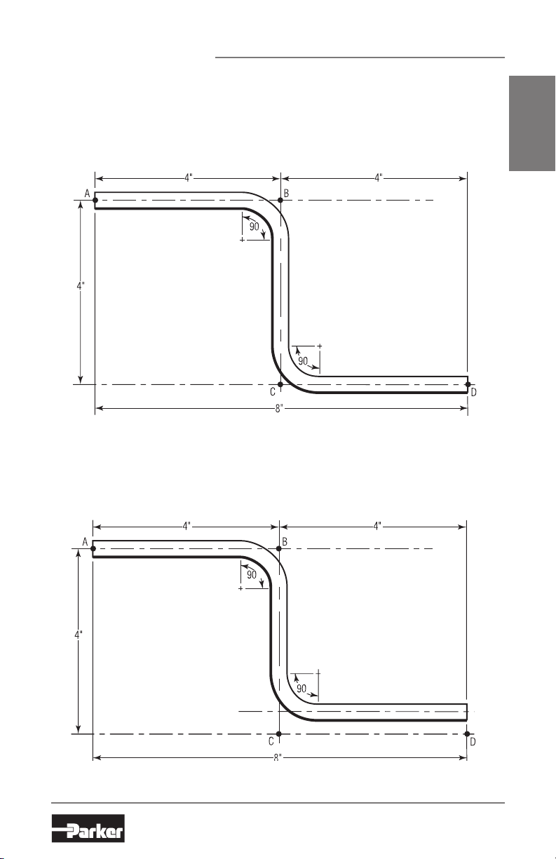
Figure 4 Measuring error on second leg (B-C) results in tube line that can
not fit at point (D).
3
Parker Hannifin Corporation
Instrumentation Products Division
Huntsville, AL USA
http://www.parker.com/ipdus
Principles of Tube Line Fabrication
Bulletin 4200-B4
Installation
Accurate bending is necessary to achieve the exact angles required
for the tube line. If you do not bend accurately, the tube line will not fit
(Figure 5).
Figure 5
You must always measure exactly and bend accurately.
2. Tube Centerline Basis for Measurement
The centerline of the tube is the basis for all tube line measurement
(Figure 6). Always measure from the centerline except from the first
bend which is measured from the end of the tube. On most benders,
the edge of the radius block is at the centerline of the tube.
Figure 6
3. You Control Accuracy
Remember only you can control the accuracy of your work. Use
good, careful workmanship at all times.
4
Parker Hannifin Corporation
Instrumentation Products Division
Huntsville, AL USA
http://www.parker.com/ipdus
Bulletin 4200-B4
Principles of Tube Line Fabrication
Tube Bending Checklist
Follow this list to insure good results on each bend.
1. Measure and mark exactly. Insert tube in bender.
2. Always try to bend in the same direction! If you backbend, be sure
to compensate for gain or pickup. Remember, gain always occurs to
the right side of the tube radius block.
3. Clamp tubing securely in bender.
4. Check to make certain length mark is tangent to desired angle on
radius block or in line with the desired degree on the link member.
5. Bend accurately to the desired angle plus springback allowance.
6. Open bender, remove tube.
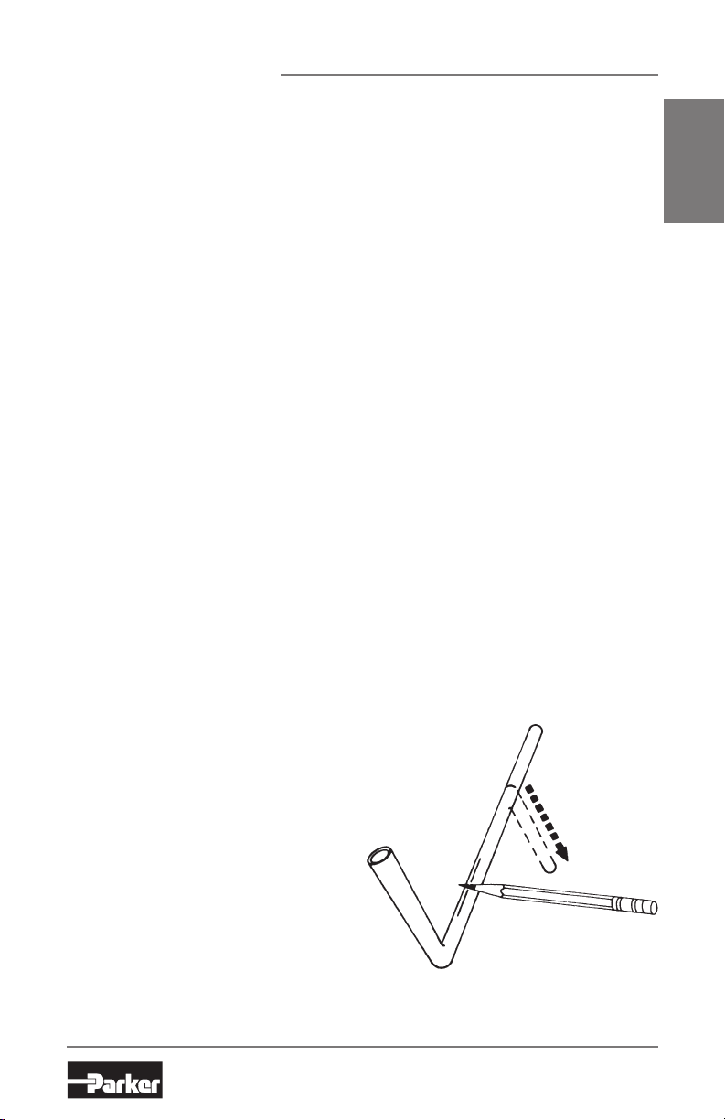
7. Double check bend angle with triangle.
8. Check measurement length with tape or ruler.
Keep Track of Changes of Plane
Benders bend in only one direction. Changes in plane are accomplished
by rotating the tubing in the bender. To insure that the tubing is correctly
placed for the desired change in plane, a reference mark on the tube is
very helpful.
Bend Direction Mark
One method for keeping track of changes
in plane is to use a longitudinal or lengthwise bend direction mark (Figure 7).
Put the mark on the side opposite the
direction in which you wish to bend.
Installation
Figure 7
5
Parker Hannifin Corporation
Instrumentation Products Division
Huntsville, AL USA
http://www.parker.com/ipdus
Principles of Tube Line Fabrication
Installation
When you put the tube in the bender, center the mark face up in the
Bulletin 4200-B4
groove of the radius block (Figure 8). This will insure that you bend in
the correct direction. It also gives you a reference mark in case you must
leave your work unfinished.
Figure 8
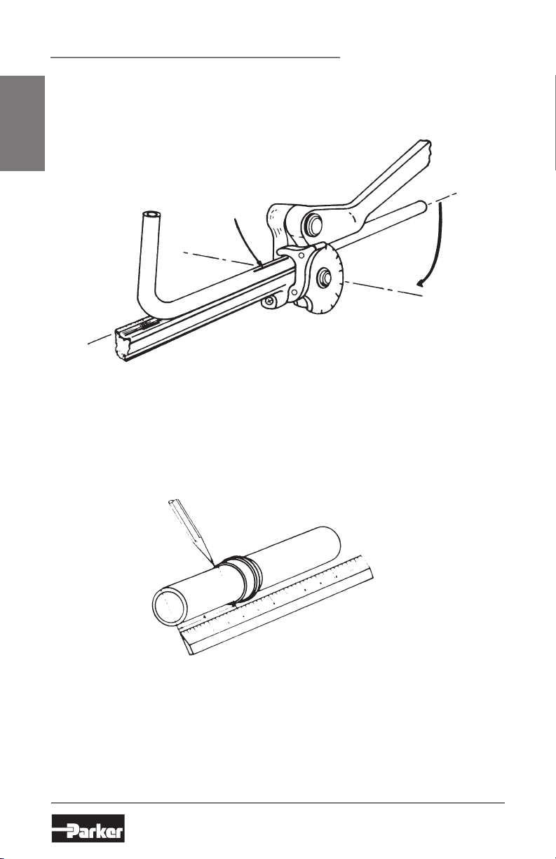
Marking the Tube
Whenever you make a mark on tubing, use a sharp pencil. Use a ferrule
as a guide to make measurement marks all the way around the tube so
that the mark is always visible (Figure 9). Don’t use grease pencils or
crayons as these make too wide a line which can easily affect accuracy.
Figure 9
Measure and Mark
Never use a sharp tool to scratch marks onto tubing. Scratches create
points where corrosion or stress concentration can ruin or dangerously
weaken the tube.
6
Parker Hannifin Corporation
Instrumentation Products Division
Huntsville, AL USA
http://www.parker.com/ipdus
Bulletin 4200-B4
Principles of Tube Line Fabrication
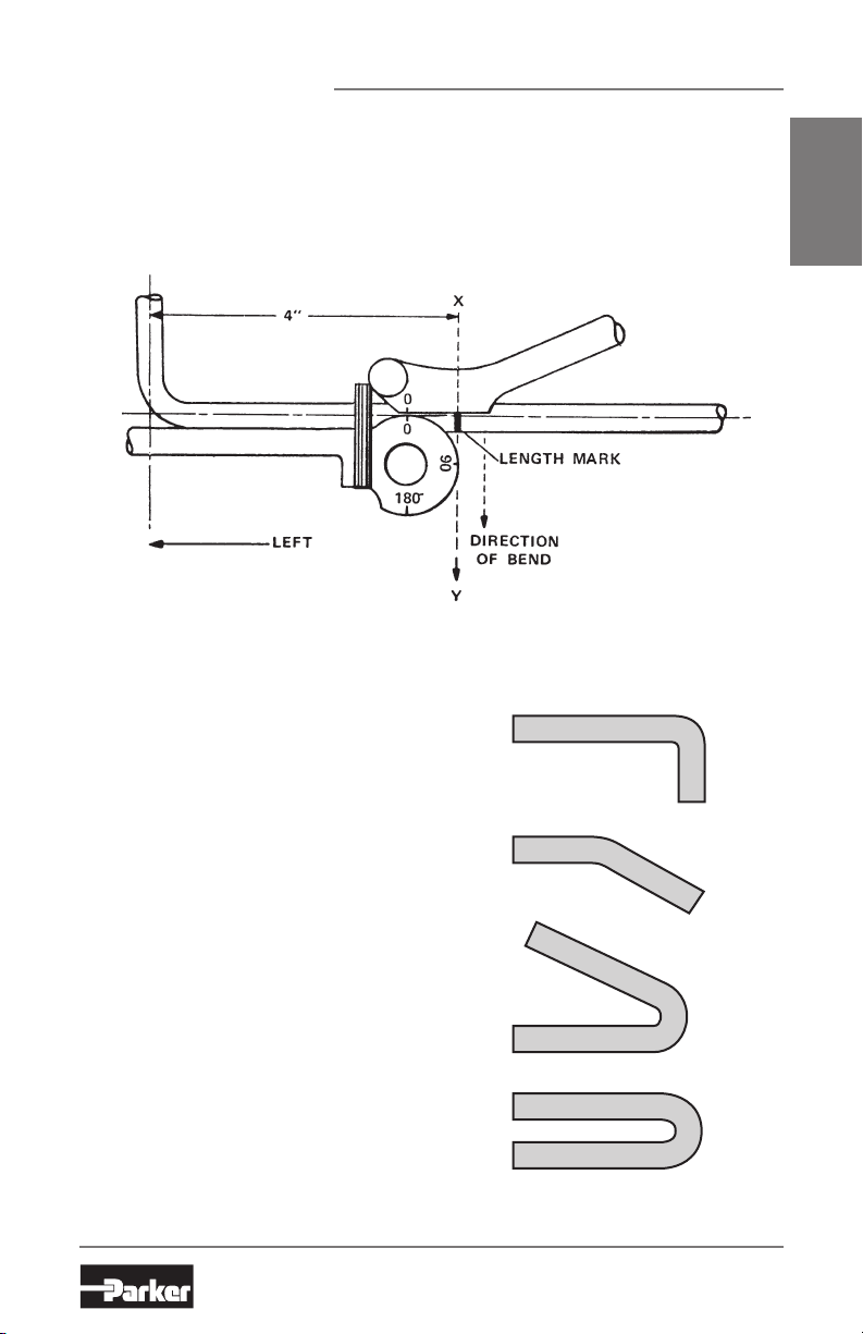
Rules for Positioning Tubing in Bender
A line which is tangent to the desired angle mark on the radius block
and which passes through the measurement mark at the centerline
of the tube, is used to control the distance between bend centerlines
(Figure 10).
Figure 10
Tube Positioning Rules
Installation
90° angles – Tangent flush with length
mark (refer to dotted line XY tangent to
radius block @ 90°, Figure 10).
Angles less than 90° – Tangent
intersects length mark at centerline.
Angles more than 90° – Position for a 90°
bend and continue on to desired angle,
i.e., 135°, 145° (i.e., length mark @ 90°
on link member).
Horseshoe or U-Bends – Measure first leg,
position for 90°, bend around to 180°.
7
Parker Hannifin Corporation
Instrumentation Products Division
Huntsville, AL USA
http://www.parker.com/ipdus
Principles of Tube Line Fabrication
Installation
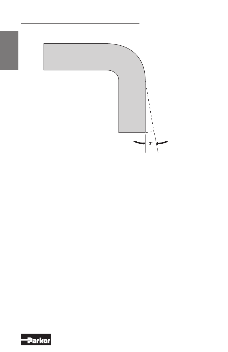
Springback 90° Bend
Figure 11
Rule of Thumb – Springback is approximately 3° for each
90° bend with stainless steel tubing.
Bulletin 4200-B4
Compensate for springback:
1. Test a piece of the material before you start fabricating a line to see
how much it springs back on a 90° bend.
2. Overbend by the amount of springback. For example, if the material
springs back 3° on a 90° bend, bend to 93° to secure a finished
90° bend, or to 46-1/2° to obtain finished 45° bend. This works
especially well with large heavy-wall tubing.
3. Remember, it is always better to underbend slightly. You can always
bend a little more if needed, but it’s almost impossible to remove or
straighten a bend, especially with large, heavy-wall tubing.
Remember – a tube bender bends – it cannot unbend.
8
Parker Hannifin Corporation
Instrumentation Products Division
Huntsville, AL USA
http://www.parker.com/ipdus
Bulletin 4200-B4
Principles of Tube Line Fabrication
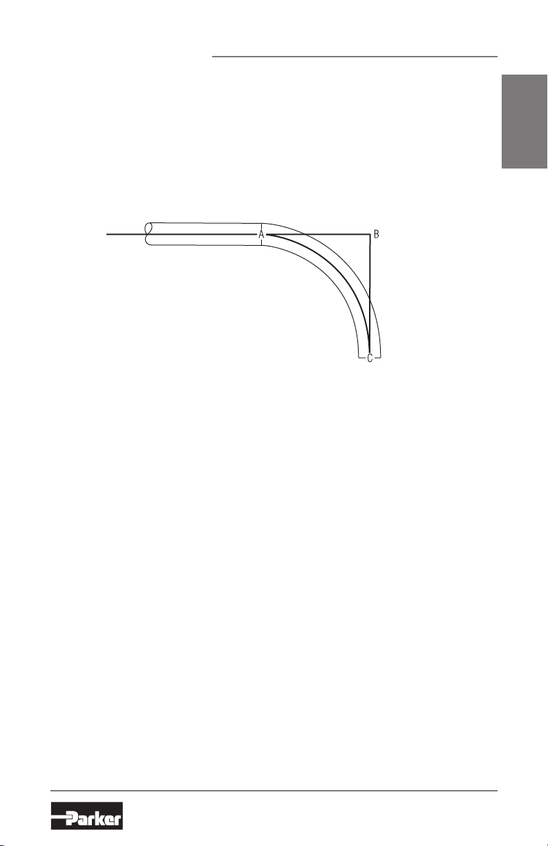
Tube Stretch or Pickup
When bent, tubing seems to stretch or pick up length. This is because
it takes a curved shortcut across the inside of the angle. A good “rule of
thumb” for most standard tubing materials and radius blocks is that the
tubing will stretch approximately one tube diameter for each 90° bend.
Triangle A-B-C – with Arc “A-C”
Figure 12
The arc “A-C” is shorter than the distance from “A” to “B”,
plus “B” to “C”.
Installation
Always try to bend in the same direction – away from the original starting end. If you reverse the direction of bending (bending towards instead
of away from the original starting end) you will “trap” the stretch. Thus, if
you unknowingly make a reverse bend of 90°, you will trap the gain, in
Table 1 (approximately one tube O.D.) and increase your length between
bends by that amount.
If bend direction for either 45° or 90° bend must be reversed, subtract
the “gain” amount listed in Table 1.
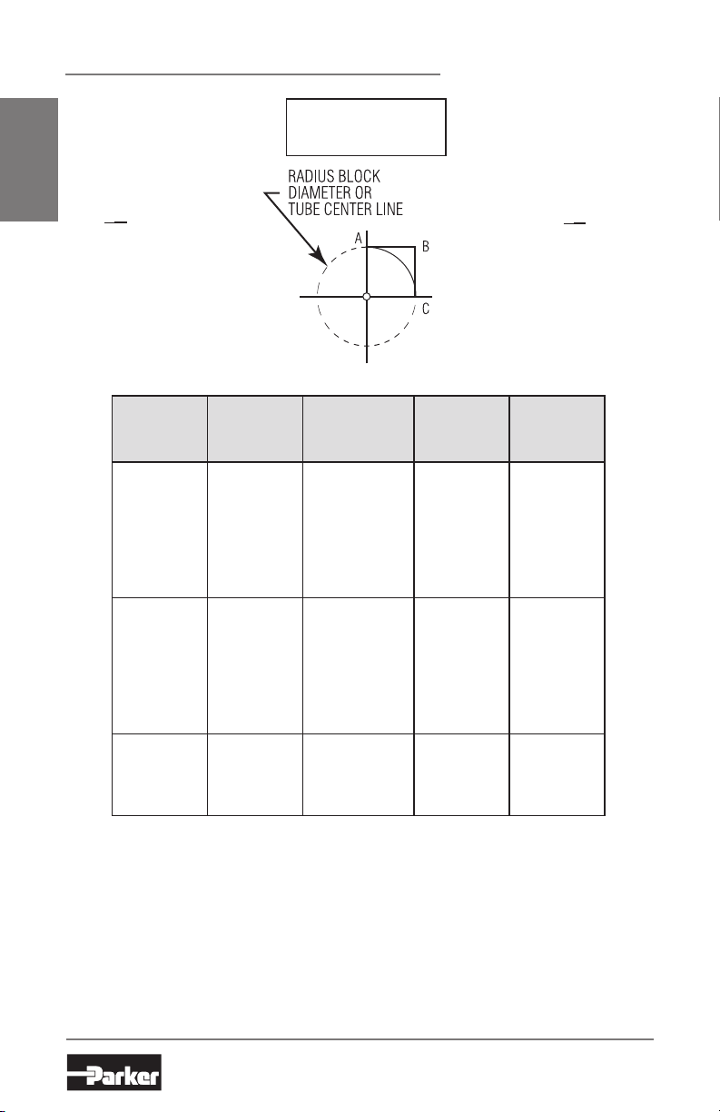
While our rule of thumb is approximately correct, the amount of stretch
is related to the diameter of the radius block used. Table 1 gives the
accurate increase in length that occurs with the most commonly used
sizes of radius blocks.
As long as you measure and bend with the tube inserted from the left,
and measure centerline, “pickup” will not affect your actual center-tocenter measurement.
9
Parker Hannifin Corporation
Instrumentation Products Division
Huntsville, AL USA
http://www.parker.com/ipdus
Principles of Tube Line Fabrication
Bulletin 4200-B4
Installation
Gain – 90° Bend
pR
2R 2
or
.429 R
Table 1
p = 3.1416
R= radius bender
Gain – 45° Bend
8284R 4
or
.043 R
Radius of
Bender
Tube Size
1/8 2 3/8 .16 .02
3/16 3 7/16 .19 .02
1/4 4 9/16 .24 .02
5/16 5 11/16 .30 .03
3/8 6 15/16 .40 .04
1/2 8 1-1/2 .64 .06
5/8 10 1-7/8 .80 .08
3/4 12 2-1/4 .97 .10
7/8 14 2-5/8 1.13 .11
1 16 3 1.29 .13
1-1/4 20 3-3/4 1.61 .16
1-1/2 24 4-1/2 1.93 .19
2 32 *8 3.43 .34
(in inches) Gain 90° Gain 45°
pR
10
Parker Hannifin Corporation
Instrumentation Products Division
Huntsville, AL USA
http://www.parker.com/ipdus

Bulletin 4200-B4
Principles of Tube Line Fabrication
Pre-Measuring
You may pre-measure a series of bends. Measure the first bend from the
end of the tube, the correct length. Compensate for each bend after the
first by subtracting the amount of gain from your chart for each 90° of
bend to allow for stretch (Figure 13). Always custom measure for the last
bend.
Example of 1/4" Tubing
Figure 13
“Rule of Thumb” Method
Compensate each measurement after the first by subtracting the gain
listed in Table 1.
Best Way to Measure
For maximum accuracy, measure and bend exactly for each individual
bend in the tubing line. We recommend the practice of Measure and
Bend, Measure and Bend, etc.
Installation
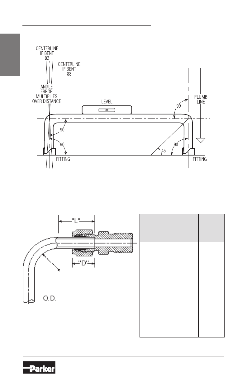
Characteristics of a Well-Made Tubing Circuit
In a well made tubing circuit or line, bends are accurate, measurement
exact. The run is plumb, square and level. Tube ends rest firmly in the
fittings and entry into the fittings is straight. Straight tube entry is very
important to insure that fittings are not under stress and can be
assembled without leaks (Figure 14).
Remember too, that length magnifies bend angles errors. If the leg
following the bend is fairly long, an error of 1° may result in the tube
line missing the desired point completely.
11
Parker Hannifin Corporation
Instrumentation Products Division
Huntsville, AL USA
http://www.parker.com/ipdus
Principles of Tube Line Fabrication
Installation
Properly Made Tube Circuit
Bulletin 4200-B4
Figure 14
Recommended Free Tubing Lengths
It is important to consider the length of tubing from the end in the fitting
body to the beginning of the bend.
Figure 15
Failure to allow for
this proper distance
can result in improper
connections, and
leaks.
12
L
Free Length
Tube
O.D.*
of Straight
Tubing*
1/16 0.50 0.38
1/8 0.70 0.52
3/16 0.75 0.56
1/4 0.80 0.61
5/16 0.88 0.66
3/8 0.94 0.69
1/2 1.19 0.94
5/8 1.25 0.98
3/4 1.25 0.98
7/8 1.31 1.05
1 1.50 1.22
1-1/4 1.94 1.61
1-1/2 2.41 1.96
2 3.25 2.65
Table 2
*All dimensions in inches.
Parker Hannifin Corporation
Instrumentation Products Division
Huntsville, AL USA
http://www.parker.com/ipdus
D
Tube
Insertion
Depth*
Bulletin 4200-B4
Principles of Tube Line Fabrication
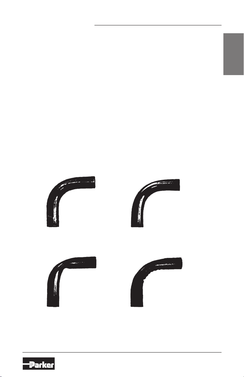
Common Causes of Imperfect Bends
Figure 16 shows an ideal bend. Bends with little or no flattening are
produced when correct equipment and methods are employed; when
proper consideration is given to co-relationship of the radius of the bend,
material wall thickness and hardness of the tube.
Figure 17 shows a flattened bend, caused by trying to bend too short a
radius, or bending smaller diameter tube in larger radius block.
Figure 18 shows a kinked and flattened bend, caused by the tube slipping
in the bender, or by using non-annealed tubing. Tubes must be firmly
clamped by clamp block to prevent slippage during bending process.
Figure 19 shows a wrinkled bend, sometimes produced when thin wall
tube is bent.
Breakage will sometimes occur when mandrel is too far forward in tube,
or when too short a radius is attempts with hard tube.
Installation
Figure 16 Good Bend Figure 17 Flattened Bend
Figure 18 Kinked Bend Figure 19 Wrinkled Bend
13
Parker Hannifin Corporation
Instrumentation Products Division
Huntsville, AL USA
http://www.parker.com/ipdus

Principles of Tube Line Fabrication
F
L
(A)
(B)
Installation
Offset Bends
Bulletin 4200-B4
To form a tube offset, it is obviously necessary to make two bends. With
these Parker hand tube benders, it is easy to make double 45° bends.
To make an offset bend simply follow the “Offset Bend Allowance” steps
below to determine the proper distance between the two 45° bends.
Here’s the procedure.
Figure 20
STEP 1 First, determine the total amount of offset required (dimension “F”
in the diagram).
STEP 2 Next, determine the angle of offset – 30° or 45°. The latter (45°)
is recommended because Parker hand benders are calibrated for 45°
bending.
STEP 3 Figure the length of the tube required to meet your offset requirements (“L” dimension) in the diagram.
For 30° bends multiply desired offset “F” x 2 = 30° offset dimension
“L”. For 45° bends multiply desired offset “F” x 1.414 = 45° offset
dimension “L”.
STEP 4 Determine where you want the offset bend of the tube to start;
and make a reference mark (A). Now measure off the “L” dimension
(determined in Step 3), starting from the reference mark and make a
second mark (B). You are now ready to make the bends.
STEP 5 Align mark (A) with reference mark 45° on bender shoe handle
(measurement end to the left) and proceed with first bend. Then align
(B) with 45° mark and make second bend in proper direction (measurement end to the left). Follow previous detailed instructions for making 45°
bends in one plane.
14
Parker Hannifin Corporation
Instrumentation Products Division
Huntsville, AL USA
http://www.parker.com/ipdus
Bulletin 4200-B4
Principles of Tube Line Fabrication
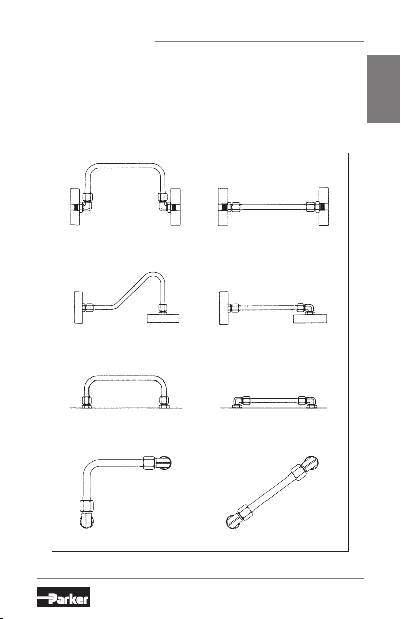
Routing of Bends
Routing of lines is probably the most difficult yet most significant of
these system design considerations. Proper routing involves getting a
connecting line from one point to another through the most logical path.
The most logical path should:
Avoid excessive strain on joints – A strained joint will eventually leak.
Correct Routing Incorrect Routing
Installation
Correct Routing Incorrect Routing
Correct Routing Incorrect Routing
Correct Routing Incorrect Routing
Figure 21
15
Parker Hannifin Corporation
Instrumentation Products Division
Huntsville, AL USA
http://www.parker.com/ipdus
Principles of Tube Line Fabrication
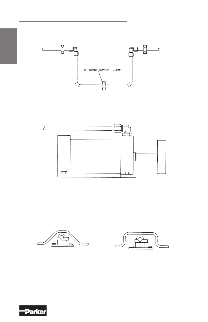
Installation
Allow for expansion and contraction – Use a “U” bend in long lines to allow
Bulletin 4200-B4
for expansion and contraction.
Figure 22 U-Bend Allowing for Expansion and Contraction
Allow for motion under load – Even some apparently rigid systems do
move under load.
Figure 23 Bent Tube Allowing for Motion Under Load
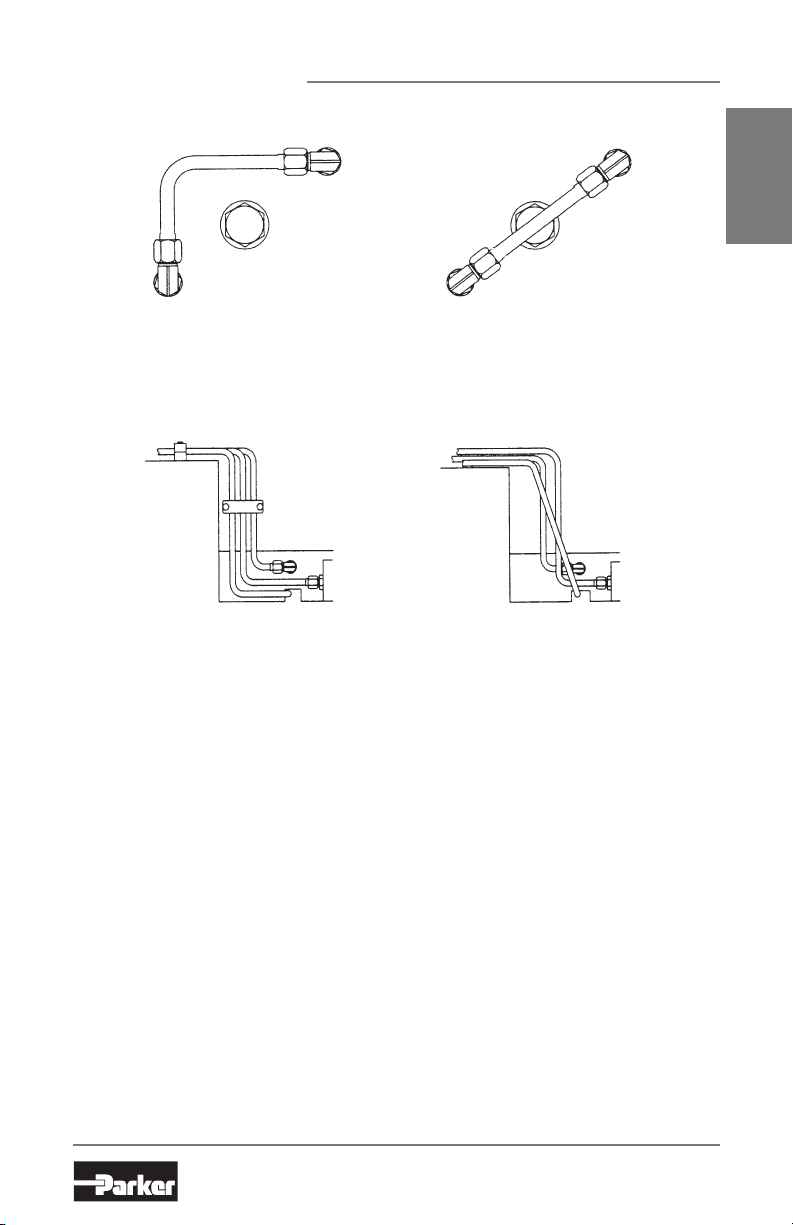
Get around obstructions without using excessive amount of 90° bends.
Pressure drop due to one 90° bend is greater than that due to two 45°
bends.
Correct Incorrect
Figure 24
16
Parker Hannifin Corporation
Instrumentation Products Division
Huntsville, AL USA
http://www.parker.com/ipdus
Bulletin 4200-B4
Principles of Tube Line Fabrication
Keep tube lines away from components that require regular maintenance.
Correct Incorrect
Figure 25
Have a neat appearance and allow for easy troubleshooting, maintenance and
repair.
Installation
Correct
Figure 26
Incorrect
Tube Clamping
Once you’ve taken the time to make good bends and installed them,
it’s not enough to just let them lay suspended in mid-air. When tubing
is left unsupported, shock and vibration will cause the tubing to shake,
and in turn, cause the fitting to loosen and leak or even allow tube to fall
through fatigue.
Tube support and clamping is a necessary requirement in the fluid
power industry. Tubing can be clamped individually, in sets, and can also
be stacked. The most important part of any clamping system is having
enough clamps to attain the final result. That being, a well supported,
vibration and noise free system.
Also, most manufacturers specify SAE and JIC approved components on
their equipment. The best way to meet these specs concerning clamps
is to utilize a clamp that employs both an upper and lower unit made of
metal and a rubber split bushing which surrounds the tube or pipe and
fits on the inside of the clamping units.
17
Parker Hannifin Corporation
Instrumentation Products Division
Huntsville, AL USA
http://www.parker.com/ipdus
Principles of Tube Line Fabrication
Installation
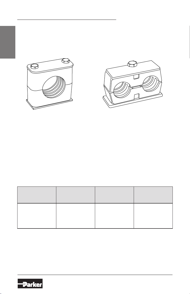
Parker Hannifin offers a tube clamp support system by the name of
Bulletin 4200-B4
“ParKlamp”. ParKlamp can clamp and support tube from 1/4" to 2" and
pipe or hose from 1/4" to 1-1/2". It comes standard in steel and uses a
rubber grommet around the tube for vibration dampening.
Standard Series –
for outside diameters from
1/4" to 2".
Clamp material: Polypropylene
Figure 27
Twin Series –
for equal or unequal outside
diameters from 1/4" to 2"
Clamp Material: Polypropylene
Below you will find a chart of recommended spacing between clamps.
We suggest you clamp as close to each bend of the tube as possible;
and you must clamp each side. This eliminates thrust in all directions.
For further information, please refer to Bulletin 4300, Industrial Tube
Fittings, Adapters and Equipment.
Equivalent
Tube
O.D.
1/4" – 1/2" 6 – 13 mm 3 ft. 0.9 m
3/8" – 7/8" 14 – 22 mm 4 ft. 1.2 m
1" 23 – 30 mm 5 ft. 1.5 m
1-1/4" & up 31 & up mm 7 ft. 2.1 m
Table 3
Tube
(mm)
Foot Spacing
Between
Supports
Spacing in
Meters
(Approx.)
18
Parker Hannifin Corporation
Instrumentation Products Division
Huntsville, AL USA
http://www.parker.com/ipdus

Bulletin 4200-B4
Instrument Tubing Selection Guide
Overview
1. Always Match Materials – I.E., Stainless steel tubing should be used
only with SS Fittings. The only exception to this rule is copper tubing
with brass fittings. Mixing materials can cause galvanic corrosion.
Galvanic Corrosion (Electrochemical)
All metals have a specific relative electrical potential. When
dissimilar metals come in contact in the presence of moisture
(electrolyte), a low energy electric flows from the metal having the
higher potential to the metal having the lower potential. The result
of this galvanic action is the corrosion of the metal with the higher
potential (more anodic). (See Galvanic Series Chart on page 20.)
2. Select proper tubing hardness – Remember Parker Instrumentation
Tube Fittings are designed to work within specific hardness ranges.
Rb 90 max. for S.S., Rb 80 recommended.
3. Select proper tubing wall thickness – Proper wall thickness is neces-
sary to accommodate accepted safety factors relative to desired
working pressures. For details on items 2 & 3 note “Instrumentation
Tubing Selection Guide” shown below and on the following pages.
Installation
4. Tubing surface finish – Always select tubing free of visible
drawmarks or surface scratches. If possible, cut off any undesirable
sections. These “deep” scratches can cause leaks when attempting
to seal low-density gases such as argon, nitrogen, or helium.
Instrument Tubing Selection Guide
Parker’s instrument tube fittings have been designed to work in a wide
variety of applications that demand the utmost in product performance.
Although Parker’s Instrument tube fittings have been engineered and
manufactured to consistently provide this level of reliability, no systems
integrity is complete without considering the critical link, tubing.
This booklet is intended to assist the designer to properly select and
order quality tubing.
Proper tube selection and installation, we believe, are key ingredients in
building leak-free reliable tubing systems.
19
Parker Hannifin Corporation
Instrumentation Products Division
Huntsville, AL USA
http://www.parker.com/ipdus
Instrument Tubing Selection Guide
+0.2 0 –0.2 –0.4 –0.6 –0.8 –1.0 –1.2
ZINC
–1.4 –1.6
LEAD
MAGNESIUM
BERYILIUM
ALUMINUM ALLOYS
CADMIUM
LOW ALLOY STEEL
AUSTENITIC NICKEL CAST IRON
ALUMINUM BRONZE
NAVAL BRASS, YELLOW BRASS, RED BRASS
TIN
COPPER
Pb-Sn SOLDER (50/60)
ADMIRALTY BRASS, ALUMINUM BRASS
MANGANESE BRONZE
SILICON BRONZE
MILD STEEL, CAST IRON
TIN BRONZE (G & M)
NICKEL SILVER
90-10 COPPER-NICKEL
80-20 COPPER-NICKEL
70-30 COPPER – NICKEL
NICKEL – ALUMINUM BRONZE
STAINLESS STEEL – TYPE 430
STAINLESS STEEL – TYPE 410, 416
SILVER BRAZE ALLOYS
NICKEL 200
SILVER
MONEL ALLOYS 400, K-500
STAINLESS STEEL – TYPES 316, 317
STAINLESS STEEL – TYPES 302, 304, 321, 347
INCONEL ALLOY 600
CARPENTER 20 Cb 3, HAYNES No. 20, CN-7M
INCOLOY ALLOY B
ILLIUM ALLOY B
TITANIUM
HASTELLOY ALLOY C
PLATINUM
GRAPHITE
Installation
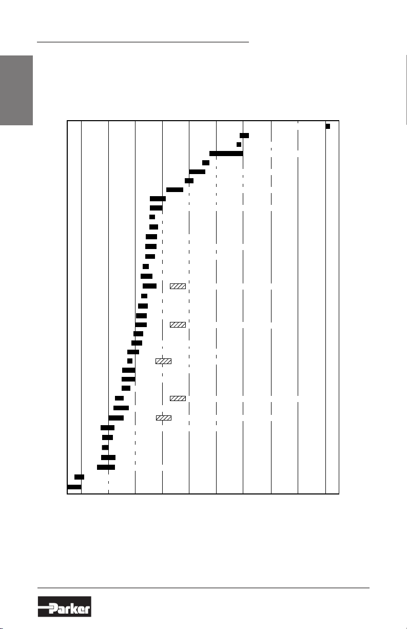
Parker does not recommend the use of dissimilar metals when putting
together a tubing/ fitting connection system.
(Cathodic) Galvanic Series Chart (Anodic)
Bulletin 4200-B4
Above represents corrosion potentials of materials in flowing seawater at temperature
in the range 10°C – 26°C. The hatched symbols indicate potentials exhibited by stainless steels in pits or crevices.
Figure 28 Galvanic Series Chart
20
Parker Hannifin Corporation
Instrumentation Products Division
Huntsville, AL USA
http://www.parker.com/ipdus
Bulletin 4200-B4
Instrument Tubing Selection Guide
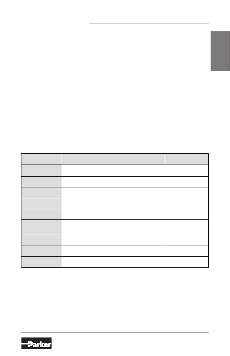
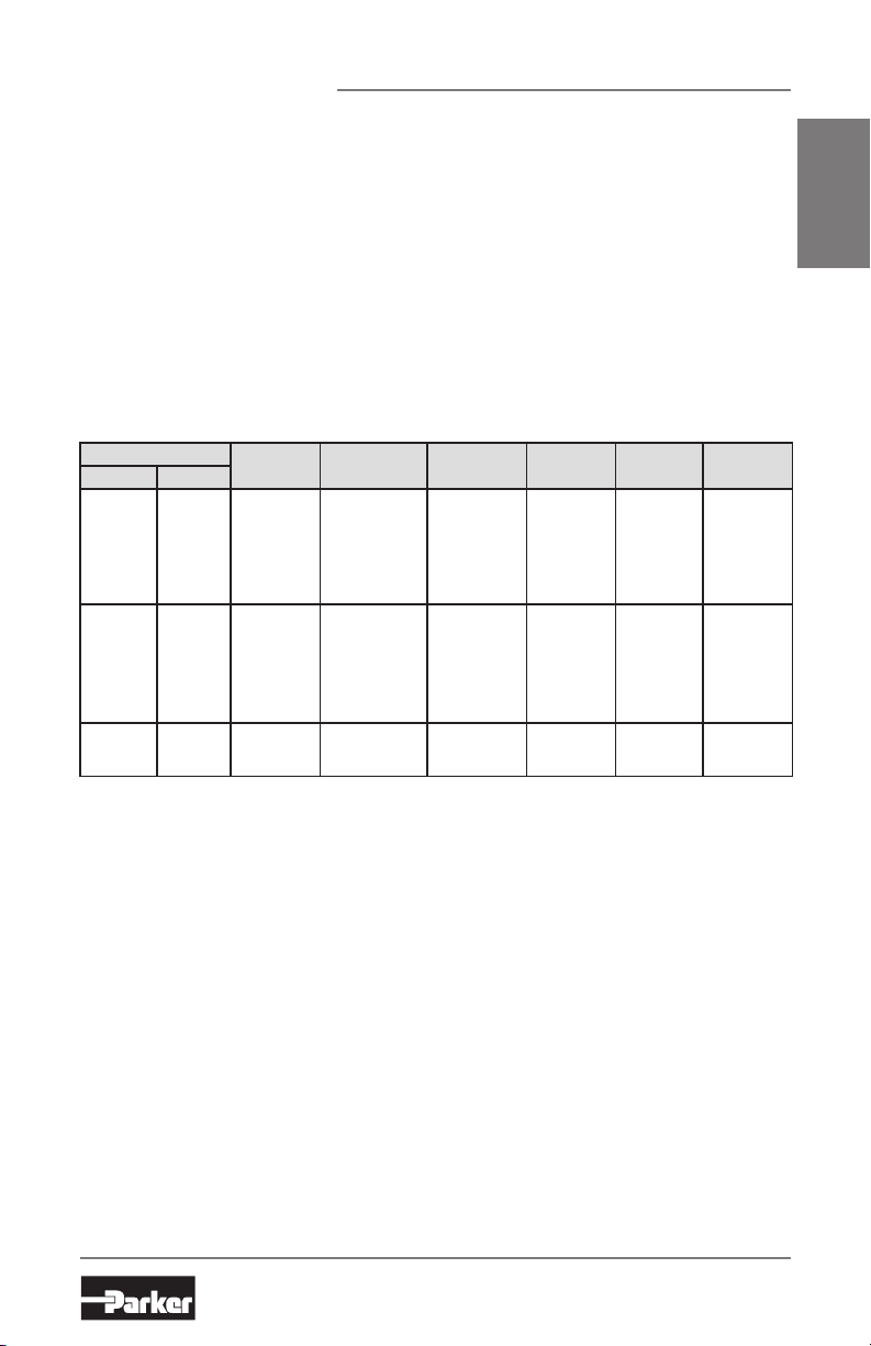
General Selection Criteria
The most important consideration in the selection of suitable tubing for
any application is the compatibility of the tubing material with the media
to be contained. Table 4 lists common materials and their associated
general application. Table 4 also lists the maximum and minimum
operating temperature for the various tubing materials.
In addition, Parker instrument fittings are designed to work on like
materials. Stainless steel fittings should be used only with stainless
steel tubing, aluminum fittings with aluminum tubing, etc. The practice
of mixing materials is strongly discouraged. The only exception is brass
fittings with copper tubing.
Dissimilar materials in contact may be susceptible to galvanic corrosion.
Further, different materials have different levels of hardness, and can
adversely affect the fittings ability to seal on the tubing.
Table 4
Tubing
Material
Stainless Steel
(Type 316)
Carbon Steel
Copper
Aluminum
®
Monel
400
®
Hastelloy
Carpenter
Inconel
Titanium
C-276
®
20
®
Alloy 600
High pressure, high temperature, generally corrosive media -425°F to 1,200°F
High pressure, high temperature oil, air, some specialty
chemicals
Low temperature, low pressure water, oil, air -40°F to 400°F
Low temperature, low pressure water, oil, air, some
specialty chemicals
Recommended for sour gas applications well suited for
marine and general chemical processing applications
Excellent corrosion resistance to both oxidizing and
reducing media and excellent resistance to localized
corrosion attack
Applications requiring resistance to stress corrosion
cracking in extreme conditions
Recommended for high temperature applications with
generally corrosive media
Resistant to many natural environments such as sea water,
body fluids and salt solutions
1. For operating temperatures above 800°F (425°C), consideration should be given to media. 300
Series Stainless Steels are suspectible to carbide precipitation which may lead to intergranular
corrosion at elevated temperatures.
2. Consideration should be given to maximum temperature ratings if fittings and/or tubing are coated
or plated. All temperature ratings based on temperatures per ASME B31.3 Chemical Plant and
Petroleum Refinery Piping Code, 1999 Edition.
The information listed in Table 4 is general in scope. For specific applications, please contact Parker’s
Instrumentation Products Division, Product Engineering Department (256) 881-2040.
Note: Hastelloy
®
is a registered trademark of Haynes International. Inconel®, and Monel® are registered
trademarks of Special Metals Corporation. Carpenter® is a registered trademark of CRS Holdings Inc.
General
Application
Recommended
Temperature Range
(-255°C to 605°C)
-20°F to 800°F
(-29°C to 425°C)
(-40°C to 205°C)
-40°F to 400°F
(-40°C to 205°C)
-325°F to 800°F
(-198°C to 425°C)
-325°F to 1000°F
(-198°C to 535°C)
-325°F to 800°F
(-198°C to 425°C)
-205°F to 1200°F
(-130°C to 650°C)
-75°F to 600°F
(-59°C to 315°C)
1
2
Installation
21
Parker Hannifin Corporation
Instrumentation Products Division
Huntsville, AL USA
http://www.parker.com/ipdus

Instrument Tubing Selection Guide
Installation
Gas Service
Bulletin 4200-B4
Special care must be taken when selecting tubing for gas service. In
order to achieve a gas-tight seal, ferrules in instrument fittings must seal
any surface imperfections. This is accomplished by the ferrules penetrating the surface of the tubing. Penetration can only be achieved if the
tubing provides radial resistance and if the tubing material is softer than
the ferrules.
Thick walled tubing helps to provide resistance. Tables 5 through 10 indicate the minimum acceptable wall thickness for various materials in gas
service. The ratings in white indicate combination of diameter and wall
thickness which are suitable for gas service.
Acceptable tubing hardness for general application is listed in Table 12.
These values are the maximum allowed by ASTM. For gas service, better results can be obtained by using tubing well below this maximum
hardness. For example, a desirable hardness of 80 Rb is suitable for
stainless steel. The maximum allowed by ASTM is 90 Rb.
System Pressure
The system operating pressure is another important factor in determining the type, and more importantly, the size of tubing to be used. In
general, high pressure installations require strong materials such as
steel or stainless steel. Heavy walled softer tubing such as copper
may be used if chemical compatibility exists with the media. However,
the higher strength of steel or stainless steel permits the use of thinner
tubes without reducing the ultimate rating of the system. In any event,
tube fitting assemblies should never be pressurized beyond the recommended working pressure.
The following tables (5 through 10) list by material the maximum suggested working pressure of various tubing sizes. Acceptable tubing
diameters and wall thicknesses are those for which a rating is listed.
Combinations, which do not have a pressure rating, are not recommended for use with instrument fittings.
22
Parker Hannifin Corporation
Instrumentation Products Division
Huntsville, AL USA
http://www.parker.com/ipdus
Bulletin 4200-B4
Instrument Tubing Selection Guide
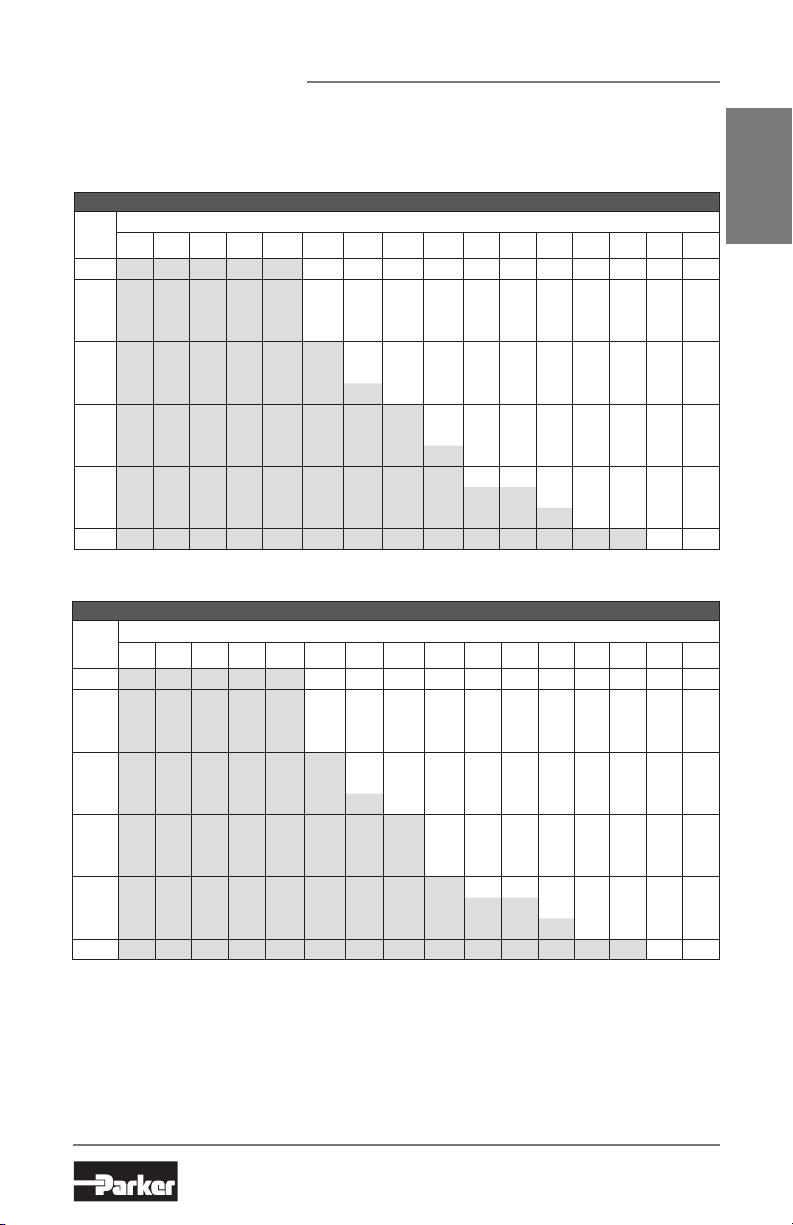
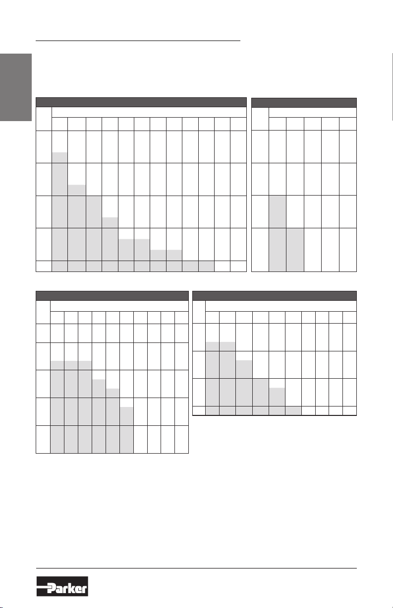
Maximum Allowable Working Pressure Tables
Ratings in gray not suitable for gas service.
Table 5*
Tube
O.D.
0.010 0.012 0.014 0.016 0.020 0.028 0.035 0.049 0.065 0.083 0.095 0.109 0.120 0.134 0.156 0.188
Size
1/16 5600 6900 8200 9500 12100 16800
1/8 8600 10900
3/16 5500 7000 10300
1/4 4000 5100 7500 10300
5/16 4100 5900 8100
3/8 3300 4800 6600
1/2 2600 3700 5100 6700
5/8 3000 4000 5200 6100
3/4 2400 3300 4300 5000 5800
7/8 2100 2800 3600 4200 4900
1 2400 3200 3700 4200 4700
1-1/4 2500 2900 3300 3700 4100 4900
1-1/2 2400 2700 3000 3400 4000 4500
2 2000 2200 2500 2900 3200
Table 6*
Tube
O.D.
0.010 0.012 0.014 0.016 0.020 0.028 0.035 0.049 0.065 0.083 0.095 0.109 0.120 0.134 0.156 0.188
Size
1/16 4800 5900 7000 8100 10300 14300
1/8 7300 9300
3/16 4700 6000 8700
1/4 3400 4400 6400 8700
5/16 3400 5000 6900
3/8 2800 4100 5600
1/2 2200 3200 4300 5700
5/8 2500 3400 4500 5200
3/4 2100 2800 3700 4200 4900
7/8 1800 2400 3100 3600 4200
1 2100 2700 3100 3600 4000
1-1/4 2100 2400 2800 3100 3500 4200
1-1/2 2000 2300 2600 2900 3400 4200
2 1700 1900 2100 2500 3000
*Notes for Tables 5 through 10:
• Allworkingpressureshavebeencalculatedusingthemaximumallowablestresslevelsinaccordance
with ASME/ANSI B31.3, Chemical Plant and Petroleum Refinery Piping or ASME/ANSI B31.1 Power
Piping.
• Allcalculationsarebasedonmaximumoutsidediameterandminimumwallthickness.
• Allworkingpressuresareatambient(72°F) temperature.
316 or 304 STAINLESS STEEL (Seamless)
Wall Thickness
316 or 304 STAINLESS STEEL (Welded)
Wall Thickness
Installation
Maximum Allowable Working Pressure Tables are continued on the following page.
23
Parker Hannifin Corporation
Instrumentation Products Division
Huntsville, AL USA
http://www.parker.com/ipdus
Instrument Tubing Selection Guide
Installation
Maximum Allowable Working Pressure Tables (cont'd)
Bulletin 4200-B4
Ratings in gray not suitable for gas service.
Table 7*
CARBON STEEL (Seamless)
Tube
O.D.
0.028 0.035 0.049 0.065 0.083 0.095 0.109 0.120 0.134 0.148 0.165 0.180
Size
1/8 8100 10300
3/16 5200 6700 9700
1/4 3800 4900 7100 9700
5/16 3800 5500 7700
3/8 3100 4500 6200
1/2 2300 3300 4500 6000
5/8 1800 2600 3500 4600 5400
3/4 2200 2900 3800 4400 5100
7/8 1800 2500 3200 3700 4300
1 1600 2100 2800 3200 3700 4100
1-1/4 1700 2200 2500 2900 3200 3700 3800
1-1/2 1800 2100 2400 2700 3000 3400 3800 4000
2 1600 1800 2000 2200 2500 2800 3000
Wall Thickness
Table 9*
ALUMINUM (Seamless)
Tube
O.D.
Size
1/8 8700
3/16 5600 8100
1/4 4100 5900
5/16 3200 4600
3/8 2600 3800
1/2 1900 2800 3800
5/8 1500 2200 2900
3/4 1800 2400 3200
7/8 1500 2100 2700
1 1300 1800 2300 2700
Wall Thickness
0.035 0.049 0.065 0.083 0.095
Table 8*
COPPER (Seamless)
Tube
O.D.
.010 .020 .028 .035 .049 .065 .083 .095 .109 .120
Size
1/16 1700 3800 5400
1/8 2800 3600
3/16 1800 2300 3500
1/4 1300 1700 2600 3500
5/16 1300 2000 2800
3/8 1100 1600 2300
1/2 800 1200 1600 2200
5/8 900 1300 1700 2000
3/4 800 1000 1400 1600 1900
7/8 600 900 1100 1300 1600
1 600 800 1000 1200 1400 1500
1-1/8 500 700 900 1000 1200 1300
1-1/4 800 900 1100 1200
1-1/2 650 750 850 950
Wall Thickness
Table 10*
Tube
O.D.
.010 .020 .028 .035 .049 .065 .083 .095 .109 .120
Size
1/16 5500 11800 16300
1/8 8100 10400
3/16 5100 6600 9600
1/4 3800 4800 7000 9600
5/16 3800 5500 7500
3/8 3100 4500 6100
1/2 2300 3300 4500 5900
5/8 2700 3700 4900 5600
3/4 2300 3100 4000 4600 5400
1 2300 2900 3400 3900 4400
MONEL 400 (Seamless)
Wall Thickness
*Notes for Tables 5 through 10:
• Allworkingpressureshavebeencalculatedusingthemaximumallowablestresslevelsinaccordance
with ASME/ANSI B31.3, Chemical Plant and Petroleum Refinery Piping or ASME/ANSI B31.1 Power
Piping.
• Allcalculationsarebasedonmaximumoutsidediameterandminimumwallthickness.
• Allworkingpressuresareatambient(72°F) temperature.
24
Parker Hannifin Corporation
Instrumentation Products Division
Huntsville, AL USA
http://www.parker.com/ipdus
Bulletin 4200-B4
Instrument Tubing Selection Guide
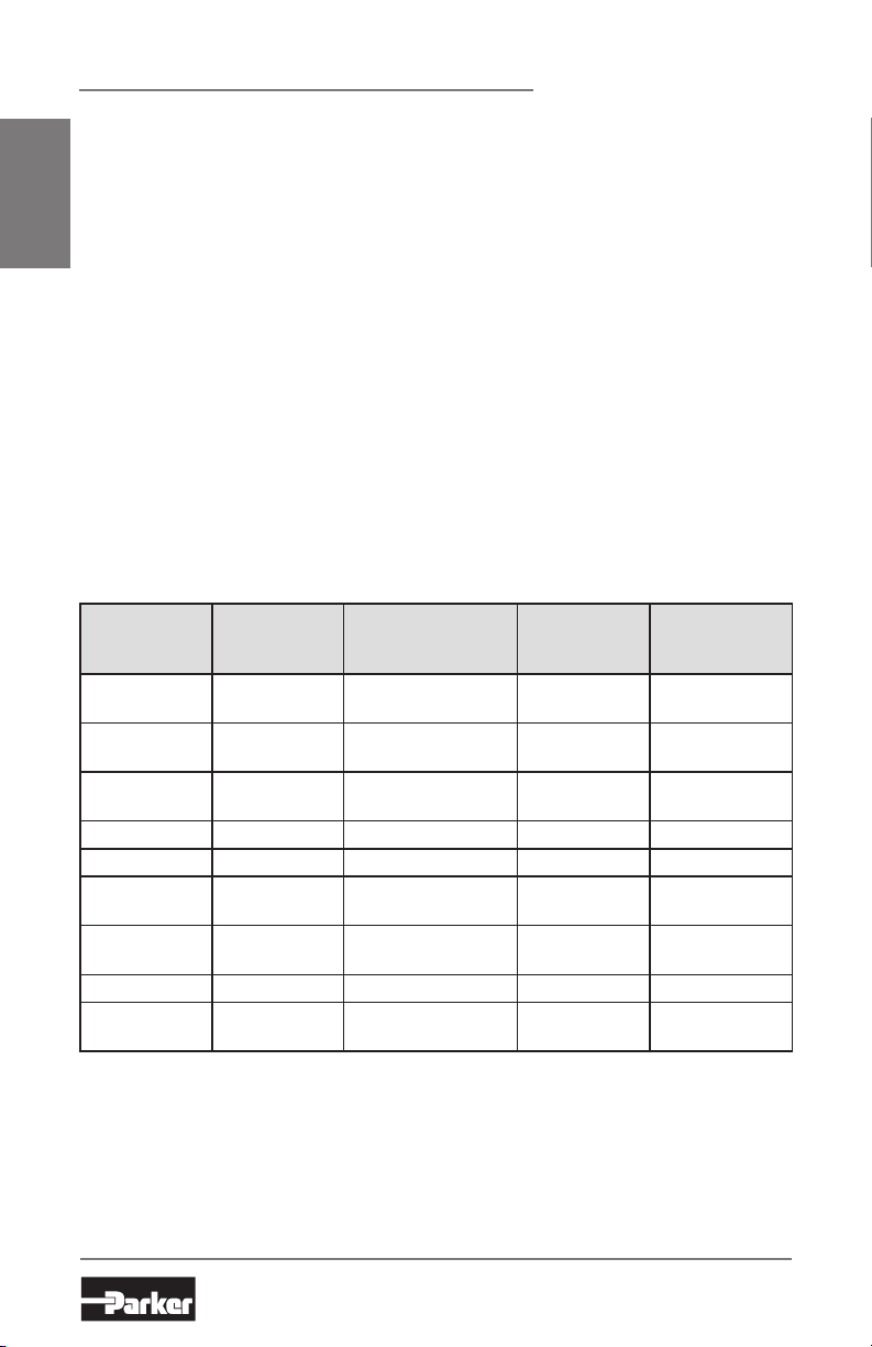
System Temperature
Operating temperature is another factor in determining the proper tubing
material. Copper and aluminum tubing are suitable for low temperature
media. Stainless steel and carbon steel tubing are suitable for higher
temperature media. Special alloys such as Alloy 600 are recommended
for extremely high temperatures (see Table 4). Table 11 lists derating
factors which should be applied to the working pressures listed in Tables
5 through 10 for elevated temperature conditions. Simply locate the correct factor in Table 11 and multiply this by the appropriate value in Tables
5 through 10 for elevated temperature working pressure.
Table 11 – Temperature Derating Factors
Temperature
Copper Aluminum
100 (38) 1.00 1.00 1.00 1.00 1.00 1.00
200 (93) .80 1.00 1.00 1.00 .96 .88
300 (149) .78 .81 1.00 1.00 .90 .82
400 (204) .50 .40 .97 .94 .86 .79
500 (260) .90 .88 .82 .79
600 (316) .85 .82 .77 .79
700 (371) .82 .80 .73 .79
800 (427) .80 .76 .59 .76
900 (486) .78 .73 .43
1000 (538) .77 .69
1100 (593) .62 .49
1200 (649) .37 .30
EXAMPLE: 1/2" x .49 wall seamless 316 stainless steel tubing has a working pressure of 3700 psi @
room temperature. If the system were to operate @ 800°F (425°C), a factor of 80% or (.80) would apply
(see Table 11 above) and the “at temperature” system pressure would be 3700 PSI x .80 = 2960 PSI.
316
SS
304
SS Steel
Monel
400°F (°C)
Installation
25
Parker Hannifin Corporation
Instrumentation Products Division
Huntsville, AL USA
http://www.parker.com/ipdus
Instrument Tubing Selection Guide
Installation
Tubing Ordering Guidelines
Bulletin 4200-B4
Tubing for use with Parker instrument fittings must be carefully ordered
to insure adequate quality for good performance. Each purchase order
must specify the material nominal outside diameter, and wall thickness. Ordering to ASTM specifications insures that the tubing will be
dimensionally, physically, and chemically within strict limits. Also, more
stringent requirements may be added by the user. All tubing should be
ordered free of scratches and suitable for bending.
A purchase order meeting the above criteria would read as follows:
“1/2 x .049 316 stainless steel, seamless, or welded and
redrawn per ASTM A-249. Fully annealed, 80 Rb or less.
Must be suitable for bending; surface scratches, and
imperfections (incomplete weld seams) are not permissible.”
Table 12 lists specific ordering information for each material.
Table 12
Material Type
Stainless Steel 304, 316, 316L
Copper K or L
Carbon Steel 1010
Aluminum Alloy 6061 ASTM B-210 T6 Temper 56 Rb
®
400 400 ASTM B-165 Fully Annealed 75 Rb
Monel
Hastelloy
C-276
Inconel® Alloy
600
Carpenter
Titanium
*B88 Copper Tube to be ordered non-engraved
Note: Hastelloy
trademarks of Special Metals Corporation. Carpenter
®
C-276 ASTM-B-622, B-626 Fully Annealed 90 Rb
600 ASTM B-167 Fully Annealed 90 Rb
®
20 20CB-3 ASTM B-468 Fully Annealed 90 Rb
Commercially
Pure Grade 2
®
is a registered trademark of Haynes International. Inconel®, and Monel® are registered
ASTM
Tubing Spec. Condition
ASTM-A-269, A-249,
A-213, A632
ASTM-B75 B68,
B88 (K or L)*
SAE-J524b, J525b
ASTM-A-179
ASTM B-338 Fully Annealed
®
is a registered trademark of CRS Holdings Inc.
Fully Annealed 90 Rb
Soft Annealed
Temper 0
Fully Annealed 72 Rb
Recommended
Hardness
60 Max.
Rockwell 15T
99 Rb 200
Brinell Typical
Max.
26
Parker Hannifin Corporation
Instrumentation Products Division
Huntsville, AL USA
http://www.parker.com/ipdus
 Loading...