

Parker Hannifin HD130, HD65 User Manual

HD65 & HD130 Stepper
Drives User Guide
For engineering For engineering
assistance in Europe: assistance in the U.S.:
Parker Hannifin plc Parker Hannifin Corporation
Digiplan Division Digiplan Division
21 Balena Close 5500 Business Park Drive
Poole, Dorset Rohnert Park, CA 94928
England, BH17 7DX USA
Telephone: 0202-699000 Telephone: (800) 358-9070
Fax: 0202-695750 Fax: (707) 584-8015
Part No: 1600.051.07 7th September 1992


IMPORTANT INFORMATION FOR USERS
Installation and Operation of Digiplan Equipment
It is important that Digiplan motion control equipment is installed and operated in such a way that all applicable
safety requirements are met. It is your responsibility as a user to ensure that you identify the relevant safety
standards and comply with them; failure to do so may result in damage to equipment and personal injury. In
particular, you should study the contents of this user guide carefully before installing or operating the
equipment.
Under no circumstances will the suppliers of the equipment be liable for any incidental, consequential or special
damages of any kind whatsoever, including but not limited to lost profits arising from or in any way connected
with the use of the equipment or this user guide.
!
High-performance motion control equipment is capable of producing rapid movement and very high forces.
Unexpected motion may occur especially during the development of controller programs. KEEP WELL CLEAR
of any machinery driven by stepper or servo motors. Never touch it while it is in operation.
High voltages exist within enclosed units, on rack system backplanes (motherboards) and on transformer
terminals. Keep clear of these areas when power is applied to the equipment.
The information in this user guide, including any apparatus, methods, techniques, and concepts described
herein, are the proprietary property of Parker Digiplan or its licensors, and may not be copied, disclosed, or
used for any purpose not expressly authorised by the owner thereof.
Since Digiplan constantly strives to improve all of its products, we reserve the right to modify equipment and
user guides without prior notice. No part of this user guide may be reproduced in any form without the prior
consent of Digiplan.
SAFETY WARNING
© Digiplan Division of Parker Hannifin plc, 1991
– All Rights Reserved –


User Guide Change Summary
The following is a summary of the primary changes to this user guide
since the last version was released. This user guide, version
1600.051.07, supersedes version 1600.051.06.
This user guide has been updated to incorporate the style common
to our user guides. Some drawings have also been updated. All
technical information remains unchanged.


CONTENTS i
Table of Contents
Introduction..............................................................................................................1
Product Description.........................................................................................1
Specification....................................................................................................1
Power Connections.........................................................................................2
Motor Connections..........................................................................................2
General Wiring & Earthing Recommendations...............................................2
Transformer Primary Connections..................................................................5
Control Signals................................................................................................8
Setting Up the Drive........................................................................................10
Motherboard Link .................................................................................10
Current Programming...........................................................................11
Stepping Mode Selection .....................................................................11
Standby Current...................................................................................12
Boost Current.......................................................................................12
Anti-resonance Dropout Speed............................................................12
Current Profile Setting (Half-step Mode)..............................................13
Fuses..............................................................................................................14
Test Points......................................................................................................14
MS20 Microstep Card ..............................................................................................15
Description......................................................................................................15
Setting Up the Microstep Card........................................................................16
Operation of the Drive Protection Systems...........................................................17
Overload Protection ........................................................................................17
Supply Failure Protection................................................................................17
Overtemperature Protection............................................................................17
Fault-finding Guide..................................................................................................19
Returning the System......................................................................................20

HD65 & HD130 STEPPER DRIVES USER GUIDE 1
Introduction
Product
Description
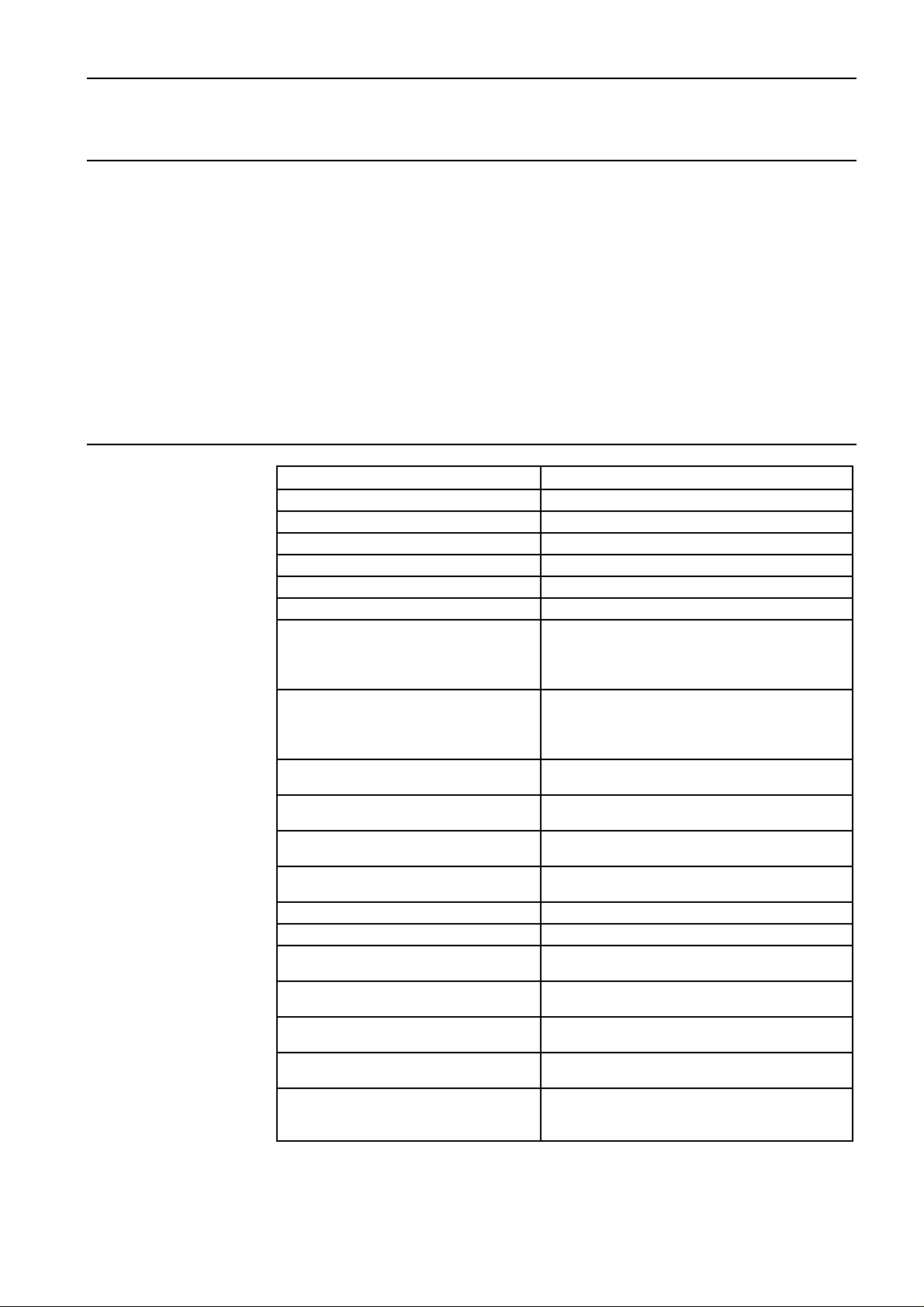
Specification
The HD65 and HD130 stepper drives are bipolar, chopper-regulated
units designed to operate with a wide range of motors. They
incorporate all power supply components for direct operation from a
mains transformer. The two drives deliver nominal motor currents of
6.5A and 13A respectively, and both operate at a motor supply of
240V DC.
All translation and current control functions are performed by a ULAhybrid translator, and this incorporates a number of useful features
including an anti-resonance circuit and automatic current square-off.
The drives can be fitted with the optional MS20 microstep card which
gives 1000 or 2000 steps/rev from a standard 200-step motor.
Nominal output current (2 phase on) 6.5A (HD65), 13A (HD130)
Motor supply voltage 240v DC
Current boost 30%
Maximum boost duration 5 seconds (internally limited)
Nominal standby reduction 50% (at rated current)
Current programming By DIL switch down to 50% of rated current
Current programming steps 0.5A (HD65), 1A (HD130)
Maximum stepping rates Full step 20kHz
Half step 50kHz
1/5 step 100kHz
1/10 step 100kHz
AC power requirements Motor supply range 86-172v AC at 7A
(HD65), 14A (HD130).
Logic supply 18-0-18 at 850mA.
Fan supply (HD130) 115v RMS at 150mA.
Auxiliary DC output +24v at 250mA (500mA with external
2200uF capacitor added)
Input logic levels Logic 1 level +11v to +13v or open circuit.
Logic 0 level <+1v or short circuit to 0v
Input impedance Clock input 1K to +12v
Other inputs 4K7 to +12v
Logic outputs Open-collector NPN, +30v max. (off),
15mA max. (on)
Operating temperature range 0° - 50°C
Maximum heatsink temperature 85°C
Suitable motor type 2/4 phase; 4, 6 or 8-lead (5-lead not
suitable)
Typical motor current rating (bipolar) 6A - 9A (HD65)
12A - 18A (HD130)
Minimum motor inductance 1.5mH (HD65)
0.75mH (HD130)
Weights 3.2kg (HD65)
4kg (HD130)
Dimensions (mm Height overall 262, pcb only 233, Depth
overall 262, pcb only 220 Width 106 (4.2"
nominal)
 Loading...