

Page 1
Automation
p/n 88-020389-01 A
Dynaserv G2 Drive
User Guide
Effective: March 1, 2002
Page 2

Introduction
Thank you very much for your purchase of the DD servo actuator DYNASERV. The DYNASERV is an outer rotor type
servo actuator that has achieved high torque, high speed, and high precision. It can be used in a wide range of
applications in the FA device-related fields, such as industrial robotics and indexing.
This technical manual explains the DYNASERV DM/SR series motors as well as its combinations with the DrvGII
drivers. Please refer to this technical manual thoroughly when you use the product.
Precautions for Using this Technical Manual
1. Please make sure that this manual is handed out to the end user.
2. Please read this manual thoroughly and understand the contents fully before proceeding to the operation of the
product.
3. Please note that the safety protection may be lost and the proper safety may not be guaranteed if the product is
not used according to the instructions described in this manual.
4. Always make sure that this manual is handy for the operator when using this product. If it is stained or lost, we
will distribute copies upon request, subject to charge.
5. This manual explains details of the features included in the product and does not guarantee to meet the specific
purpose of the customers.
6. No part of this manual may be reprinted or reproduced in any form without permission.
7. The information in this document is subject to change without notice.
8. The information contained in this document is believed to be accurate at the time of publication, but if you notice
any inaccuracies, errors, or omissions, please contact our sales or service staff.
-1-
Page 3

Regarding the safe usage of this device
! This product has been marked with and signs so that it can be used safely. Ignoring precautions and
prohibitions related to these signs and using this product in an incorrect way may cause danger to the life and body
of the operator. Always follow the precautions and observe the prohibitions explained below.
! Please make sure to understand the information given below completely before you start reading the technical
manual.
! Please keep the technical manual and this sheet handy while using the product. In addition, make sure that they are
handed out to the operator of the product.
!!!!
Warnings
!!!!
!!!!
Warnings
!!!! Warning about rotation:
The motor periphery part of this device rotates at a high speed. People and objects should not be placed within the
rotational radius when a load is attached to the motor.
!!!! Warning about electric shock:
Make sure to connect the device to ground to avoid electric shock.
Make sure to turn the power off when connecting cables to the driver part.
Make sure to turn the power off when removing the cover of the driver part while performing adjustment
operations, etc.
!!!! Fire and electric shock warning:
If any abnormalities such as abnormal noise, bad smell, or release of fumes that coming from the device are
detected while it is in operation, turn the power off immediately, pull out the power supply plug, and contact us.
If the device is dropped or given a strong impact, stop the operation immediately, turn the power off, and contact
us.
Do not operate at power supply voltages other than the one indicated on the device.
!!!! Fire and electric shock warning:
Avoid dropping or inserting metal shards or combustible materials, or allowing water to get into the opening parts
of the device (e.g., the clearance between the rotor and stator of the motor part, or the air vent of the driver part).
In such an eventuality, turn the power off immediately and contact us.
The cables coming out from the motor part or the bottom of the index part should not be forcibly bent, twisted,
pulled, heated, or placed under a heavy object.
Never try to remodel or repair the device by yourself.
-2-
Page 4

Precautions
! This product has been marked with and signs so that it can be used safely. Ignoring precautions and
prohibitions related to these signs and using this product in an incorrect way may cause danger to the life and body
of the operator. Always follow the precautions and observe the prohibitions explained below.
! Please make sure to understand the information given below completely before you start reading the technical
manual.
! Please keep the technical manual and this sheet handy while using the product. In addition, make sure that they are
handed out to the operator of the product.
! Make sure to read the technical manual before using the device.
Operational mistakes and faulty wiring may result in damages and failure of the device.
! Make sure to check the wiring once more before turning the power on.
Faulty wiring may result in fire, electric shock, or damage of the device.
! Confirm that the proper combination of motor and driver parts is used. Using the device with an incorrect
configuration may result in failure. (Be sure to confirm the model--MODEL--on the rating nameplates.)
! Make sure the conditions of temperature, humidity, dust, etc. are as specified for the installation and storage
environments.
! Do not block the air vent of the device. Keep the specified open space around the device as well. Poor ventilation
may cause overheating, leading to failure.
!!!!
!!!!
Precautions
!!!!
! Some of the motor parts are very heavy; please pay sufficient attention to this when carrying and installing the
parts. If the weight is more than 10kg (22.04 lbs), carrying or lifting tools should be used as much as possible.
! Both the motor and driver parts should be installed in the specified orientation.
! Keep the protection cover (transparent plastic plate) attached on the power supply terminal part of the driver. It is
provided to prevent inadvertent electric shock accidents.
-3-
Page 5
Handling Precautions
1. Do not install the motor in reverse direction in such a way that the rotor of the motor is fixed and the stator rotates.
2. Make sure to turn the power off before removing the side panel of the driver to set jumpers, etc. Touching the high
voltage part inside the driver is dangerous.
3. This motor rotates at a high speed and with a high torque. Take the rotation radius into consideration and pay
special attention to the prevention of any dangerous situations that may occur during the operation when a load is
attached to the motor.
4. Make sure to ground the ground terminal to earth.
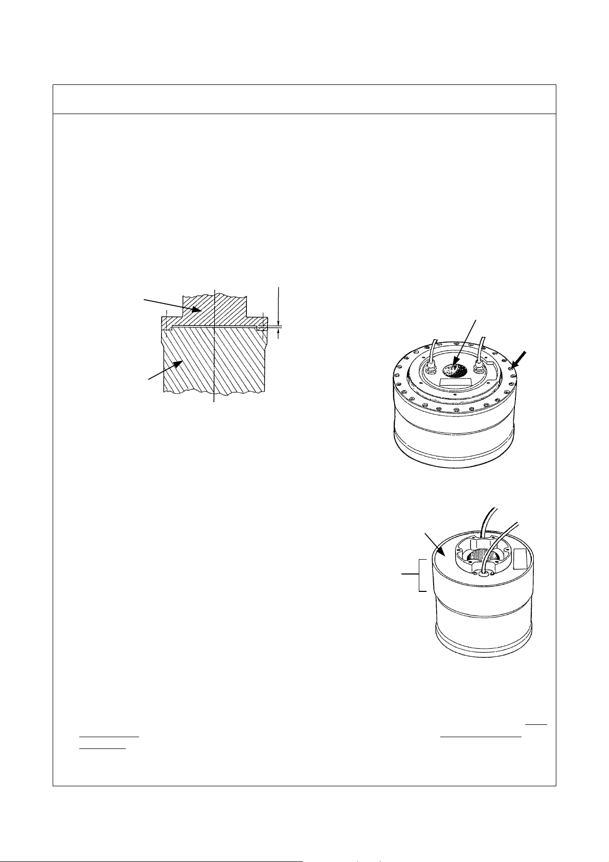
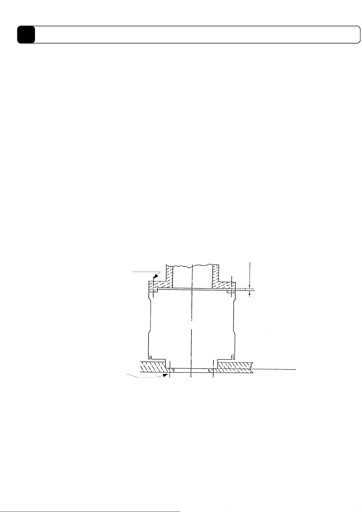
5. When attached a load to the rotor, make sure to keep a clearance of 1 mm or more between the load and the upper
surface of the motor in order to maintain the surface precision. Furthermore, never push or squeeze an object into
the shaft hole. (See the figure below.)
Attached part
1mm or more
Rotor
When feeding an object through the shaft
hole, make sure to secure a clearance of
at least 1mm on one side.
Shaft hole
6. Do not touch the bolts (indicated by the arrow) that fix the
bottom part of the rotor (see the figure to the right). If these bolts
are loosened or tightened, the commutation angle will become
inaccurate, which may result in uneven rotation (this applies only
to the DM series).
DM series motor
7. The motor surface is magnetized; do not place things that can be affected by magnetism close to it.
8. The motor part shown in the figure to the right includes a
magnetic resolver. Strong force, impacts, or magnetic fields
Bottom cap
should not be applied to the motor part (this applies only to the
DR series).
Magnetic
9. Make sure to use load attachment screws that are shorter than the
resolver
effective depth of the thread in the motor part. Depending on the
model, if a screw exceeds the effective thread depth, the function
may be impaired (this applies only to the DR series).
DR series motor
10. The motor is neither dust-, drip- nor water (oil)-proof; the motor should be installed in carefully chosen
environments.
11. If the motor will be oscillating or rotating at small angles (50° or less), it should be allowed to oscillate at an angle
of 90° or more for approximately 10 times (running-in operation) each time it has made 10,000 small-angle
oscillations in order to prevent poor lubrication of the bearing.
12. In order for the motor and driver to be compatible with each other, they must be of the same model.
-4-
Page 6

13. Never attempt to disassemble or remodel the motor and driver. If such service is necessary, please contact us. We
assume no responsibility for products that have been disassembled or remodeled without permission.
14. For the DYNASERV DR series motors, a coating has been applied on the load attachment surface of the upper
surface of the motor and the stator on the lower surface in order to prevent rust. When starting to use the product,
wipe off the coating completely with cloth or paper soaked in a petroleum or chlorine solvent before assembling. If
any of the coating remains, it may affect the mechanical precision.
Rust-proof
coated
surface
15. Do not place the motor on the floor and other surface in the manner shown in the figure below when carrying and
installing the DYNASERV. The cables are crushed by the motor’s own weight and the copper wires may be broken
inside the cables. If it cannot be avoided to place the motor in such a manner, a support bench should always be
placed so that the cables are lifted. Furthermore, if the cables need to be bent when installed in a device, etc., the
minimum bending radius should be 50 mm or more. The cables are not strong enough to live up to robot cable
specifications, so they should not be bent repeatedly.
An example of a DM series motor
An example of a DM series motor
The minimum
bending radius
should be
50mm or more.
The minimum
bending radius
should be
50mm or more.
-5-
Page 7
16. Do not perform a withstanding voltage test on this device. If such a test is performed without discretion, the
circuits may be damaged. If such test must be conducted, make sure to contact us.
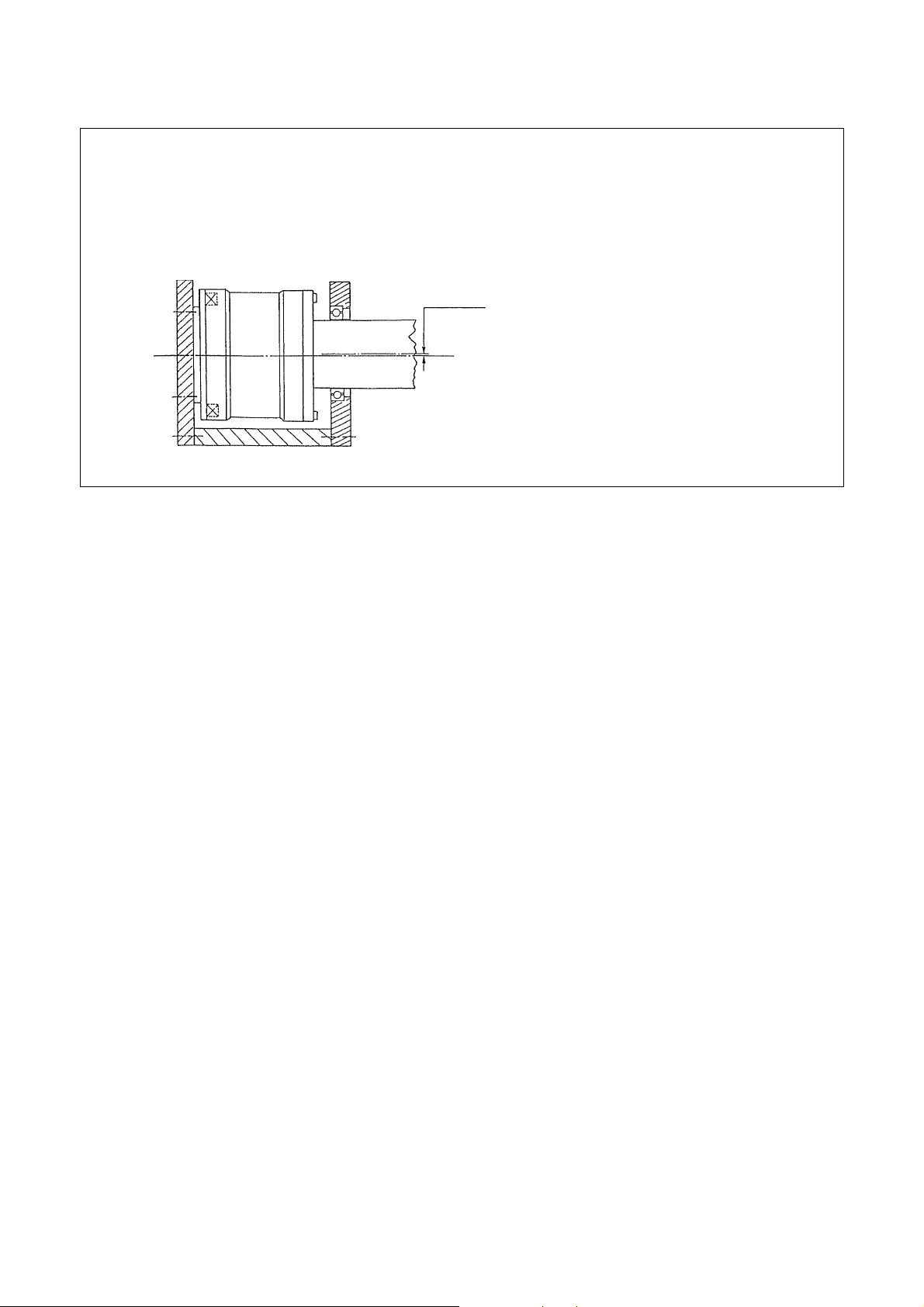
17. When connecting the motor with a load, the centerlines of both cores should be aligned to a sufficient degree.
Please note that if the deviation between the two cores becomes 10 µm or more, the bearings inside the motor may
be damaged.
The core deviation should
be 10
mm or less.
µ
-6-
Page 8

Table of Contents
Introduction..........................................................................................................................1
Chapter 1 Overview of the Product 1-1
1.1 About the DYNASERV DM/DR Series ................................................................... 1-2
1.2 About the DrvGII Type Driver ................................................................................. 1-3
1.3 Product Configuration .............................................................................................. 1-4
1.4 Model Names and Codes .......................................................................................... 1-5
1.5 Name and Function of Each Part .............................................................................. 1-6
1.6 System Configuration Diagram .............................................................................. 1-10
Chapter 2 Installation 2-1
2.1 Installation of the Motor ........................................................................................... 2-2
2.2 Installation of the Driver........................................................................................... 2-3
Chapter 3 Connection and Wiring 3-1
3.1 Diagram of Overall Connection................................................................................ 3-2
3.2 Cable Specification List............................................................................................ 3-3
3.3 Connection between Motor and Driver .................................................................... 3-4
3.4 Wiring of Motor, AC Power Supply, and Ground Cable.......................................... 3-6
3.5 Wiring of Encoder Cable .......................................................................................... 3-8
3.6 Wiring of Controller Cable....................................................................................... 3-9
3.7 Wiring of Sensor Brake Terminal ........................................................................... 3-10
3.8 Wiring of Regenerative Alarm Contact <CNA>
(For 500W Level Drive Only) ................................................................................ 3-11
Chapter 4 Basic Settings for Operating the Motor 4-1
4.1 Procedure (Flowchart) .............................................................................................. 4-2
4.2 Preoperation check.................................................................................................... 4-3
4.3 Installing the PC Utility on the PC ........................................................................... 4-6
4.3.1 Procedure .......................................................................................................................................4-6
4.3.2 Startup............................................................................................................................................4-8
4.4 Preparation................................................................................................................ 4-9
4.4.1 Selecting Communication Port ......................................................................................................4-9
4.4.2 Selecting Channels.........................................................................................................................4-9
4.4.3 Displaying Communication Strings.............................................................................................4-10
4.4.4 Main Menu...................................................................................................................................4-11
4.5 Setting the Status to Servo ON ............................................................................... 4-12
4.6 Auto-tuning............................................................................................................. 4-14
4.7 Performing Homing Operation ............................................................................... 4-16
-i-
Page 9

4.8 Performing the Basic Settings of Pulse Commands ............................................... 4-18
4.8.1 About Position Command Pulse Input.........................................................................................4-18
4.8.2 Example of Operation..................................................................................................................4-19
Chapter 5 Functions 5-1
5.1 Parameters and Monitors .......................................................................................... 5-2
5.1.1 General Parameters........................................................................................................................5-2
5.1.2 Mechanical Setting Parameters......................................................................................................5-2
5.1.3 Monitors.........................................................................................................................................5-2
5.2 Operation Functions.................................................................................................. 5-3
5.2.1 Jog Move........................................................................................................................................5-3
5.2.2 Test Operation................................................................................................................................5-4
5.2.3 Auto-Tuning Operation ..................................................................................................................5-4
5.2.4 Homing Move................................................................................................................................5-5
5.2.5 Mechanical Setting Mode ..............................................................................................................5-9
5.3 Coordinate System.................................................................................................... 5-9
5.3.1 Coordinate System.........................................................................................................................5-9
5.3.2 Switching Position Command Pulse Weights ................................................................................5-9
5.4 Control System ....................................................................................................... 5-10
5.4.1 Velocity Control Part....................................................................................................................5-11
5.4.2 Position Control Part....................................................................................................................5-12
5.4.3 Feed Forward...............................................................................................................................5-12
5.4.4 Servo Stiffness Parameter ............................................................................................................5-13
5.5 Acceleration/Deceleration Function ....................................................................... 5-14
5.5.1 Velocity Override Function..........................................................................................................5-14
5.5.2 Velocity Profile ............................................................................................................................5-15
5.6 Other Functions ...................................................................................................... 5-17
5.6.1 Settling Wait, Position Settling Status, and Positioning Status ....................................................5-17
5.6.2 Velocity Monitor and Analog Monitor.........................................................................................5-18
5.6.3 Brake Signal.................................................................................................................................5-18
5.7 Special Parameter Processing ................................................................................. 5-19
5.7.1 Internal Generation of Parameter Initial Values ...........................................................................5-19
5.7.2 Limiting and Checking Maximum Velocity When Changing Simplified Scaling
Weighted Data and Maximum Velocity Parameters.....................................................................5-19
5.7.3 Auto Conversion and Clear Functions When Changing Simplified Scaling Weighted Data.......5-20
5.7.4 Limiting the Maximum Parameter Values ...................................................................................5-20
Chapter 6 Control Interfaces 6-1
6.1 Terminal Function..................................................................................................... 6-2
6.1.1 Connection, Setting, and I/O Mapping ..........................................................................................6-2
6.1.2 Explanation of Terminals ...............................................................................................................6-3
6.1.3 Electrical specifications .................................................................................................................6-4
6.1.4 I/O logic setting..............................................................................................................................6-5
6.2 Position Command Pulse Input ................................................................................ 6-6
6.3 Encoder Pulse Output ............................................................................................... 6-6
6.4 Operations................................................................................................................. 6-7
6.4.1 Starting an Operation.....................................................................................................................6-7
6.4.2 Aborting an Operation ...................................................................................................................6-7
6.4.3 Timing Charts ................................................................................................................................6-8
-ii-
Page 10

6.5 Other Inputs .............................................................................................................. 6-9
6.5.1 Pulse Weight Selection PLS_DIRECT ..........................................................................................6-9
6.5.2 Position Control Bandwidth Selection FN.....................................................................................6-9
6.5.3 Velocity Control Bandwidth Selection GAIN................................................................................6-9
6.5.4 Settling Width Selection POSW [1..0] ...........................................................................................6-9
6.5.5 Disable Position Control Integral Operation PACT .......................................................................6-9
6.5.6 Error reset (ERR_RESET).............................................................................................................6-9
6.5.7 Servo ON SERVO........................................................................................................................6-10
6.5.8 Current Limit Input ......................................................................................................................6-10
Chapter 7 RS232C Interfaces 7-1
7.1 Overview .................................................................................................................. 7-2
7.2 Connection and Setting ............................................................................................ 7-2
7.3 Communication Specifications ................................................................................ 7-4
7.4 @ Commands ........................................................................................................... 7-6
7.4.1 Start @3: Field 0 .........................................................................................................................7-6
7.4.2 Stop @2 ......................................................................................................................................7-6
7.4.3 Abort @1 ....................................................................................................................................7-6
7.4.4 Error reset @4.............................................................................................................................7-6
7.4.5 Homing offset position setting @10 ...........................................................................................7-7
7.4.6 Jog move command @11: Field 0...............................................................................................7-7
7.4.7 Other convenient commands..........................................................................................................7-7
7.5 Parameter Commands............................................................................................... 7-8
Chapter 8 DrvGII PC Utility 8-1
8.1 Overview .................................................................................................................. 8-2
8.1.1 Overview of the Operation Menu ..................................................................................................8-2
8.1.2 Overview of the Action Menu........................................................................................................8-2
8.1.3 Overview of the Data Management Menu .....................................................................................8-2
8.2 Installation ................................................................................................................ 8-3
8.2.1 Installation under Windows 95/98/98SE/Me/NT4.0/2000.............................................................8-3
8.2.2 Starting the PC Utility....................................................................................................................8-5
8.3 Preparation................................................................................................................ 8-6
8.3.1 Selecting a Communication Port....................................................................................................8-6
8.3.2 Selecting Channels.........................................................................................................................8-6
8.3.3 Displaying Communication Strings...............................................................................................8-7
8.3.4 Main Menu.....................................................................................................................................8-8
8.4 Operation Menu ........................................................................................................ 8-9
8.4.1 Terminal .........................................................................................................................................8-9
8.4.2 Servo Tuning................................................................................................................................8-14
8.4.3 Oscilloscope.................................................................................................................................8-16
8.5 Action Menu ........................................................................................................... 8-19
8.5.1 Homing ........................................................................................................................................8-20
8.5.2 Jog Move......................................................................................................................................8-22
8.5.3 Test Operation..............................................................................................................................8-23
8.6 Data Management Menus ....................................................................................... 8-24
8.6.1 Parameter Manager......................................................................................................................8-24
8.6.2 I/O Set..........................................................................................................................................8-27
8.6.3 Pulse Set.......................................................................................................................................8-30
-iii-
Page 11

Chapter 9 Operation Display Pendant ........................................................................... 9-1
9.1 Overview................................................................................................................... 9-2
9.2 Features and Part Names .......................................................................................... 9-2
9.3 Switching Displays ................................................................................................... 9-3
9.4 Terminal Mode Display ............................................................................................ 9-4
9.5 Parameter Monitor Display....................................................................................... 9-5
9.6 Parameter Settings Display....................................................................................... 9-6
9.7 I/O Monitor Display.................................................................................................. 9-7
9.8 Special Command Display........................................................................................ 9-8
Chapter 10 Maintenance and Inspection ....................................................................... 10-1
10.1 Maintenance and Inspection of the Motor Part....................................................... 10-2
10.2 Maintenance and Inspection of the Driver Part ...................................................... 10-2
10.3 Replacing the Battery for Memory Backup............................................................ 10-2
10.4 Backup and Restore Operations of Driver Memory Contents................................ 10-3
10.4.1 Backup Operation ........................................................................................................................10-3
10.4.2 Restore Operation ........................................................................................................................10-4
10.5 Motor Problems and Corrective Actions ................................................................ 10-5
Chapter 11 Specifications...............................................................................................11-1
11.1 Standard Specifications ...........................................................................................11-2
11.2 Torque - Speed Characteristics ................................................................................11-8
11.3 External Dimensions (Unit: mm).............................................................................11-9
11.4 Restrictive Conditions for the Frequency of
Repeated Operations (DR5000B Series Only) ......................................................11-13
-iv-
Page 12

Chapter 1
Overview of the Product
1.1 About the DYNASERV DM/DR Series
1.2 About the DrvGII Type Driver
1.3 Product Configuration
1.4 Model Names and Codes
1.5 Name and Function of Each Part
1.6 System Configuration Diagram
1-1
Page 13

1
Overveiw of the Product
1.1 About the DYNASERV DM/DR Series
The DYNASERV servo motor, is a high speed, high torque, and high precision outer rotor type direct drive motor.
The DM series motors are contained in an aluminum chassis and have a built-in optical encoder. There are four
models in the A series with output torques of 50 to 200N⋅m and five models in the B series with torques of 15 to
75N⋅m. The outside diameters are 264 mm for the A series and 160 mm for the B series. Each has a shaft hole of
58 mm and 25 mm in diameter at the center, respectively.
The outer shapes of the small-diameter and flat type DM series motors have successfully been made flatter and
smaller in diameter based on the basic performance of the conventional DM/SD series. An outer diameter of 116
mm and a height (thickness) of 45 mm, respectively, are achieved for the DM small-diameter type and the DM
flat type.
Both types are equipped with an optical encoder, which is characteristic of the DM series, and have the added
features of high resolution and high mechanical precision. They are actuators with excellent output-to-space
ratios and the best available option for servos for semi-conductor manufacturing devices, precision test devices,
etc. They can be used in various applications.
The DYNASERV DR series is a series of operational direct drive motors that was developed based on the fieldproven DM series to satisfy new demands. There are six A type models (50 to 400N⋅m) with an outer diameter
of 264 mm (10 inches), seven E type models (30 to 250N⋅m) with an outer diameter of 205 mm (8 inches), and
five B type models (8 to 60N⋅m) with an outer diameter of 150 mm (6 inches). In addition, there is a 5000B/E
type (consisting of five high-speed type models).
Moreover, in addition to the above standard models, several special type models are also available, such as lightweight types, types with flanges, types with brakes, and high mechanical precision installation surface types.
1-2
Page 14

1.2 About the DrvGII Type Driver
The DrvGII type driver is a digital servo driver with a RS232 communication, developed as the successor to the
conventional SD/SR/TM type driver. Not only have the functions been improved, but also the driver box volume
has been made smaller, and it can support the DYNASERV rotation type motors, as well as the LINEARSERV
series motors that are of the direct drive type.
The features include the following:
(1) The size of the driver is reduced to approximately half of the previous size (comparison within our
company).
(2) The internal resolution is increased by a factor of four for the DM series and a factor of two for the DR
series.
(3) It can now support most of the models of the DYNASERV and LINEARSERV series.
(4) A sophisticated utility is now available and an oscilloscope function has been included as well.
1
1-3
Page 15
1
Overveiw of the Product
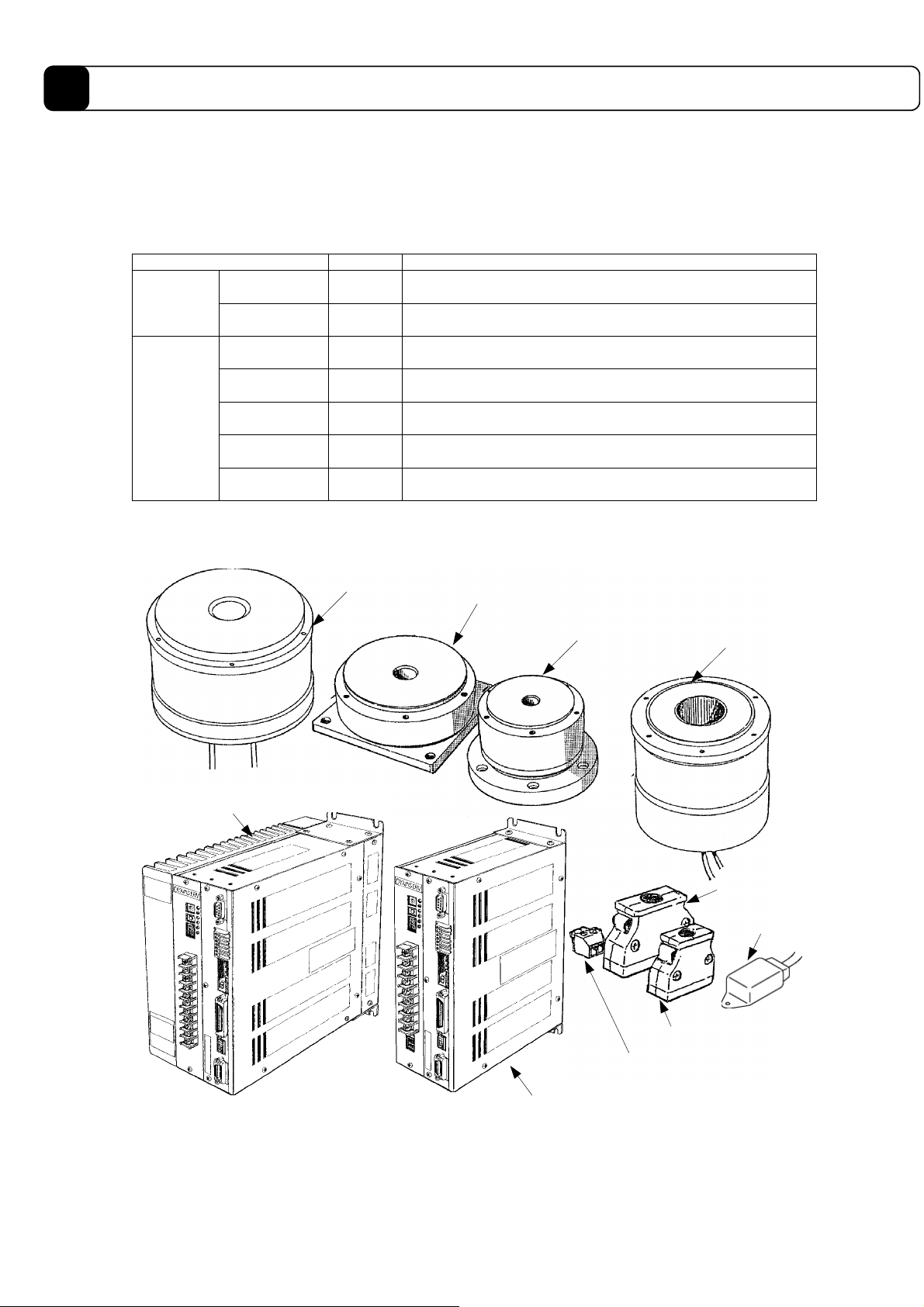
1.3 Product Configuration
The following shows the configuration of this product. Upon unpacking, please check the model name and code
of the product’s main unit, whether or not all the standard accessories are included, and also the quantity
supplied.
Part name Number Notes
Motor part 1
Main body
Driver part 1
Connector for
driver CN2
Connector for
driver CN4
Standard
accessory
* Supplied for drivers whose interface type is the I/O contact type.
** Supplied only for 500W level drivers with regenerative terminals
Connector for
driver CN5*
Terminal for
driver CNA**
Regenerative
resistor **
The external appearance varies depending on the model
name/code.
The external appearance varies depending on the model
name/code.
1
1
1 Made by Phoenix Contact MC1, 5/6-ST-3, 81
1 Made by Phoenix Contact MC1, 5/2-ST-5, 08
1
Made by Honda Tsushin Kogyo (connector) PCR-S20FS
(cover) PCR-LS20LA1
Made by Honda Tsushin Kogyo (connector) PCR-S50FS
(cover) PCR-LS50LA
80W 60Ω (for 100V) or 80W 200Ω (for 200V)
Driver part (2kW level)
With regenerative unit
Motor part/DM series
Motor part/DM1004B
Motor part/DM1004C Motor part/
DR series
Connector for CN4
Regenerative
terminal
Connecto for CN2
Connector for CNA
Driver part
(500W level)
Note: The exact shape varies depending on the model you ordered. Refer to the figure showing the outer
dimensions for more details.
1-4
Page 16

1.4 Model Names and Codes
There are restrictions on the combination of specifications. Please check with our sales staff before determining
the specification.
(1) Motor
!
Motor series name
(DM or DR)
!
Design version
(1: standard/5: high-speed)
!
Maximum output torque
(N-m, three-digit number)
!
Motor type/outer diameter (A:φ264/B:φ160/C:φ116/E:φ205)
!
Destination
(0: domestic)
!
Motor part special shape
(0: standard/B: light-weight/C: with flange/
D: with mechanical brake/F: with base)
!
Mechanical precision - only for models requiring mechanical precision.
Omitted if it is not required
(-1: mechanical precision of 5 mm or less/-2: mechanical precision of 10 mm or less/µm
-3: mechanical precision of 20 mm or less)
!
With compatibility function
□□□□□□□□□-□*
1
(2) Driver
□□□□□□□□□□-□□□_
!
Driver series name (UD for DM and UR for DR)
!
Motor type/
(four-digit number of the motor, one line of alphabet letters)
!
Box type/
(first digit 0: domestic standard/second digit A: 500W level without regenerative
terminal, B: 500W level with regenerative terminal, K: 2kW level with built-in
regenerative unit, L: 2kW level without regenerative unit)
!
Current/
(A: 5A-DM small-diameter/B: 6A-DM flat/C: 15A-DMB type, DRB type, DR5000B type /
D: 20A-DMA type, DRA type, DRE type, DR5000E type)
!
Voltage/1: 100V system, 2: 200V system
Interface/(first digit/S: pulse train position command,
!
!
Option/0: none, N: with notch filter
!
CE marking/no mark: no CE specification, *C: with CE mark specification*
Note: 1. Compatibility between the motor and driver is valid only between the same models.
second digit/A: contact I/O voltage 12 to 24V + position command input;
differential, B: contact I/O voltage 5V + position command input; differential)
This means that, for the standard models, the motor and driver are compatible only when the designations
of the five digits in motor type (DR""""") and driver type (UR"""""
) are the same.
2. Separate selection is required for the driver without 2 kW class regenerative unit.
1
1-5
Page 17
1
Overveiw of the Product
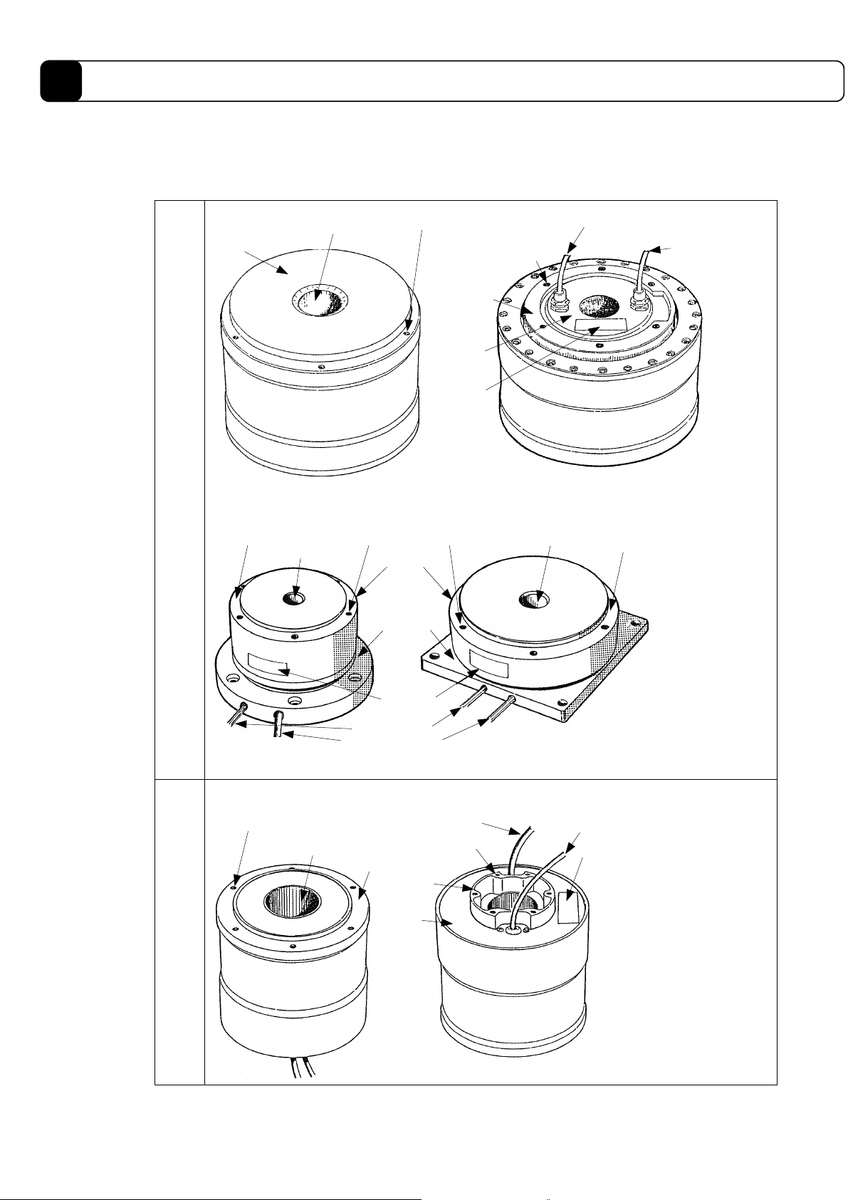
1.5 Name and Function of Each Part
(1) Motor Part
DM
series
Rotor
Load installation
surface
Shaft hole
(Upper surface)
Shaft hole
Load installation screw
Bottom cap
nameplate
Load installation
screw
Rotor
Base part
(stator)
Stator installation
screw
Stator
Rating
Encoder cable
(Bottom surface)
Shaft hole
Motor cable
Load installation
surface
DR
series
(DM1004C)
Load installation screw
Shaft hole
Rating
nameplate
Motor cable
Encoder cable
Stator installation
Rotor
Stator
Bottom
cap
Motor cable
screw
(DM1004B)
Encoder cable
Rating
nameplate
1-6
Page 18
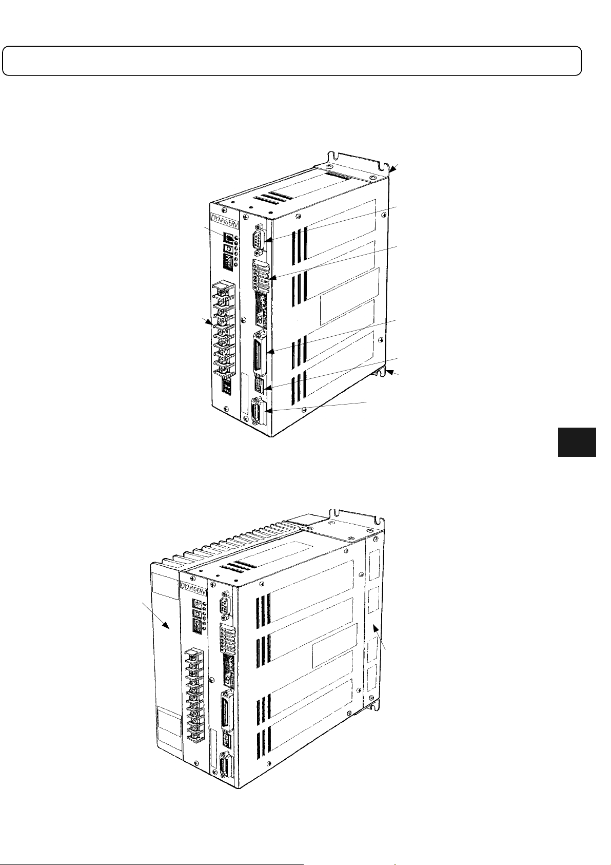
(2) Driver part
! 500W level
(A model with regenerative terminal is shown)
Setting switch
and status LED
display part
Mounting bracket
<CN1>RS232C
connnector
<TB2> Sensor brake
terminal
Connection of power
<TB1>
supply and motor cable
! 2kW level
(A model with a regenerative terminal is shown)
Heat sink
<CN4> Contact I/O connector 1
<CN3> Analog monitor connector
Mounting bracket
<CN2> Encoder resolver connector
1
1-7
Regenerative unit
Page 19
1
Overveiw of the Product
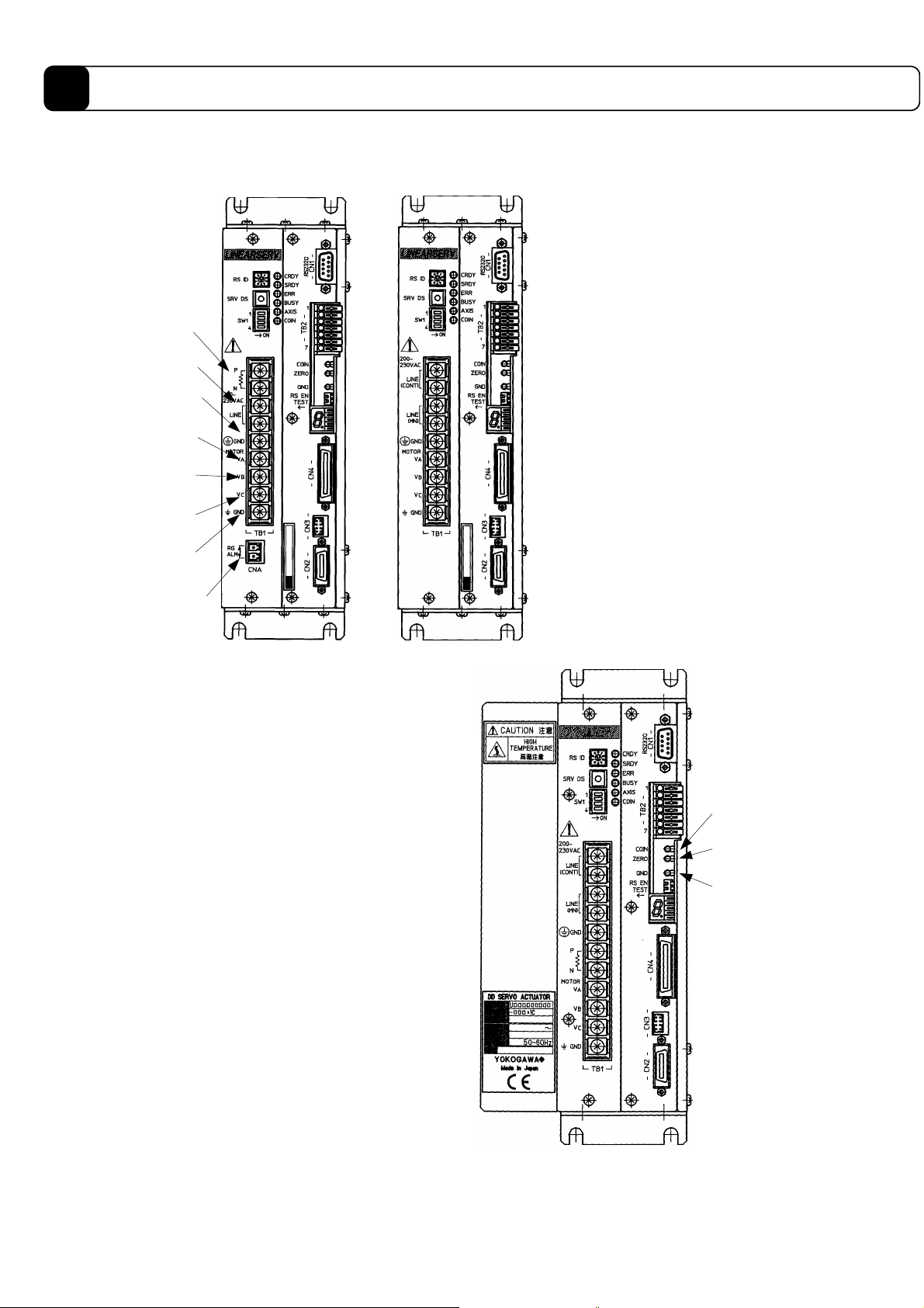
(3) Details of the Front Panel of the Driver
!
500W level
(with regenerative terminal)
Regenerative
terminal
Power supply
terminal
Power supply
ground terminal
Motor cable
phase A terminal
Motor cable
phase B terminal
Motor cable
phase C terminal
Motor cable
ground terminal
Regenerative error
<CNA>
connector
(without regenerative terminal)
!
500W level
!
2kW level
Signal ground
terminal
ZERO signal
terminal
Settling signal
terminal
Note: (1) All the items shown are of the contact I/O type.
(2) The power supply ground terminal and the motor cable ground terminal are connected within the driver
chassis.
1-8
Page 20
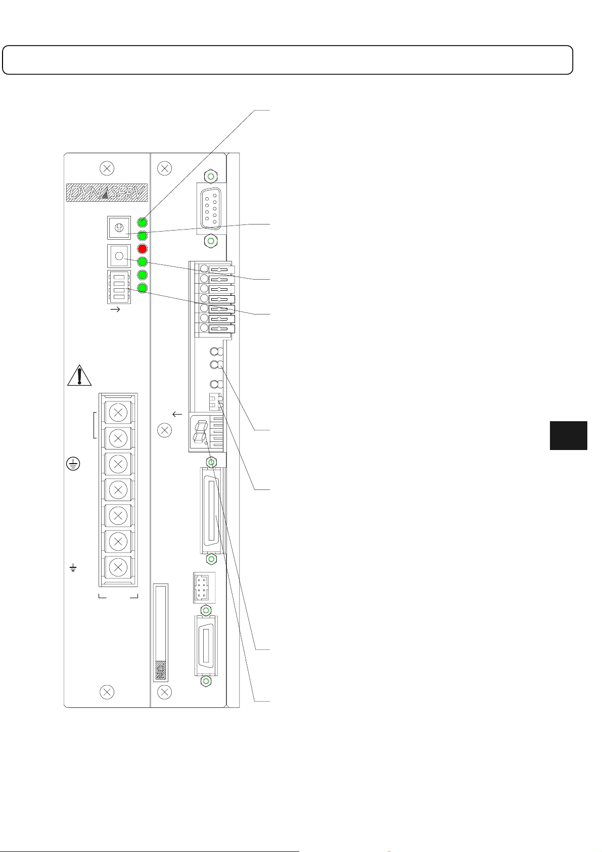
[Details of Setting Switches and Status Display LEDs]
Status display LEDs
CRDY CPU ready Indicates that the driver finished its initial
SRDY Servo ready
ERR Error status
BUSY Busy Indicates that the driver is currently
AXIS Axis is operating Indicates that the axis is currently operating
COIN Settling status Indicates that the axis is in its position
COIN
ZERO
GND
RS EN
TEST
RS232C
- CN1 -
1
- TB2 -
7
- CN4 -
- CN3 -
RS-ID Rotary switch
The communication method of the RS232C interface is set according
to the status of this switch when the power is turned on.
0 Single channel communication
1 to 9 Multi-channel communication. The value corresponds to
SRV-DS Servo disable switch
The servo is turned off for as long as this switch is pressed, regardless
of the command status of the RS232C interface and PLC interface.
SW1 Slide switch
When the power is turned on, the operation status of the driver is
determined by the status of these switches.
bit1 Reset all
bit2 Reserved
bit3 Reserved
bit4 Maintenance operation setting
Check terminal
COIN Settling Indicates that the axis is in its position settling
ZERO Zero signal status
GND Digital ground
PSW1 Piano switch
bit1 Test operation
bit2 RS-232C operation enable
RS ID
SRV DS
200230VAC
LINE
GND
MOTOR
V
V
V
GND
SW1
A
B
C
0
1
9
2
8
7
6
5
1
4
ON
CRDY
3
4
SRDY
ERR
BUSY
AXIS
COIN
TB1
processing and went into its normal status.
operating.
(dwell operation)
settling status.
the ID of the slave station.
If this bit is on when the power is turned on, all driver
information is reset to the default status at shipping.
If this bit is on when the power is turned on, the driver is set
in maintenance operation status. Normally, this bit should be
set to off.
status.
(LED display indicates the Zero signal status.)
Starts test operation when the lever is up.
Ends test operation when the lever is down.
Enables or disables the following
commands from the RS-232C interface
depending on the status when the power is
turned on.
Commands to be disabled: @1 Abort
@2 Stop
@3 Stop
@11 Jog
Lever up: Enable
Lever down: Disable
1
- CN2 -
Error display LED
Displays an error code when an error occurs.
When resetting: "0" (lit)
When operating: "." (flashing)
CN4 Controller interface connector
1-9
Page 21
1
Overveiw of the Product
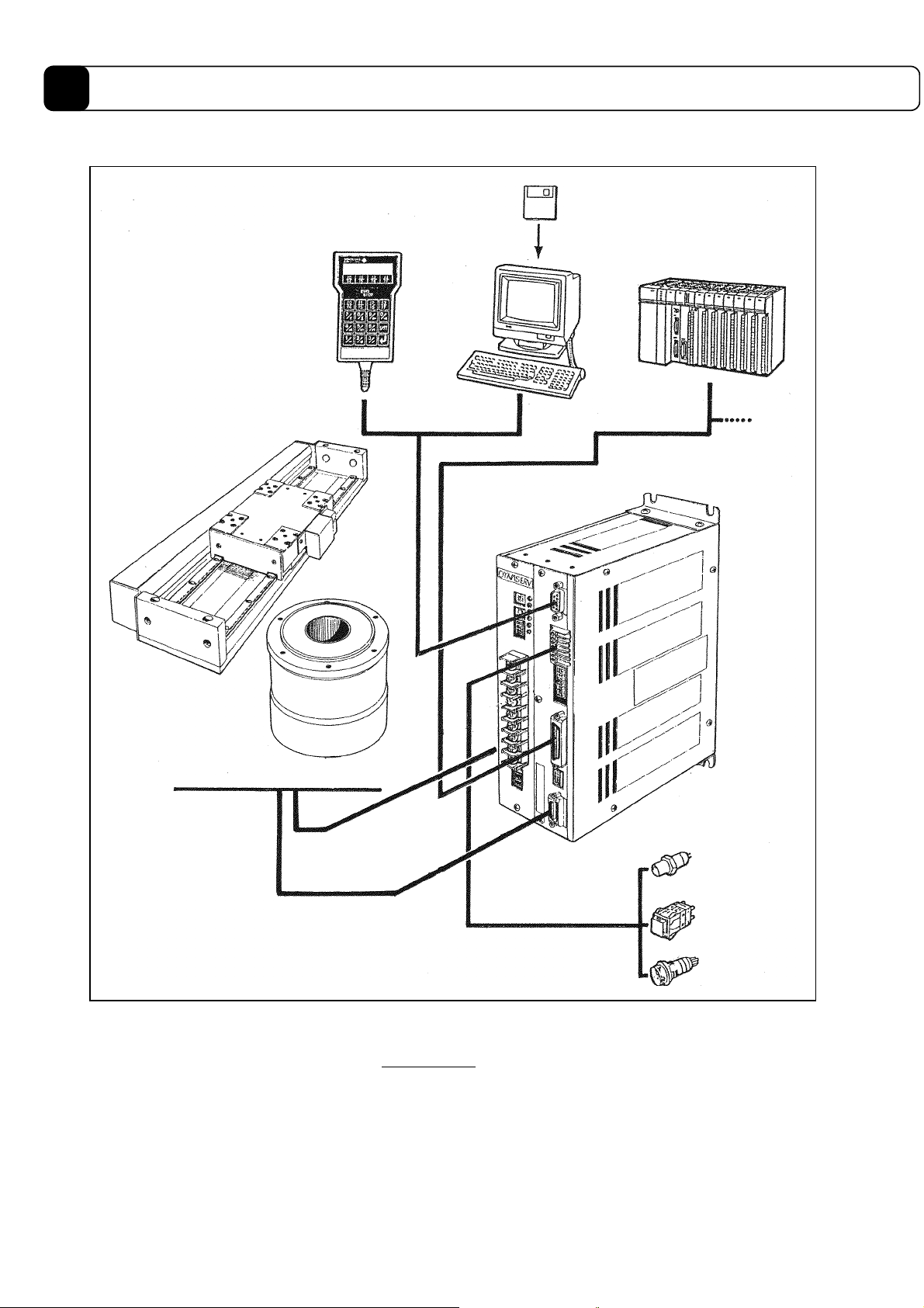
1.6 System Configuration Diagram
Operation display pendant
(PC)
LINEARSERV motor part
<LM series>
PC utility floppy disk
<Utility>
(PLC)
I/O monitor
board
DYNASERV motor part
<DM/DR series>
DrvGII type driver
(Home position
sensor)
(Over travel sensor)
(Over travel sensor)
Note: The allowable combinations between the DYNASERV motors and the DrvGII drivers are as follows.
(1) The 500W level driver can only be used with the DM1004B/1004C.
(2) All other DM and DR series should be used with the 2kW level driver. Note that they cannot be used
with the 500W level driver.
1-10
Page 22

Chapter 2
Installation
2.1 Installation of the Motor
2.2 Installation of the Driver
2-1
Page 23
2
Installation
When you receive the product, verify the model name and code of the product’s main unit, whether all the
standard accessories are included, and that the combination of a motor and a driver is correct before you begin
installation and wiring.
2.1 Installation of the Motor
The motor part can be installed and used in either a horizontal or a vertical position. However, if installed in a
wrong way or position, the life of the motor may be shortened or the motor may fail. Always follow the
instructions explained below.
(1) Installation Position
The motor part is designed based on the assumption that it is used indoors. Therefore, choose the location of
installation so that it satisfies the following conditions:
! It should be indoors and not in a place where it can be exposed to corrosive and/or volatile gases.
! The ambient air temperature should be from 0 to 45 °C.
! There should not be too much dust or particles, the ventilation should be good, and the humidity should
be low.
Note: The DYNASERV is not drip- or water (oil)-proof. If it is used in such an environment, a proper drip- or
water (oil)-proof cover should be applied.
(2) Mechanical Installation
! When installing a load on the rotor of the motor, make sure to secure a clearance of 1 mm or more
between the upper surface of the motor and the installed part in order to maintain the surface accuracy.
! The clamping torque of the screws used to install the rotor and stator of the motor should be equal to or
less than the value indicated below.
! The surface flatness where the motor is fixed should be 0.01 mm or less.
Rotor mounting screw
Clamping torque (maximum)
A/E type: 21N-m (210kgf-cm)
B type: 11N-m (110kgf-cm)
DM1004B/1004C: 2N-m (20kgf-cm)
Motor
Stator mounting screw
Clamping torque (maximum)
A/E type: 21N-m (210kgf-cm)
B type: 11N-m (110kgf-cm)
DM1004B/1004C: 2N-m (20kgf-cm)
1mm or more
Flatness of fixing
surface: 0.01mm
Note: When tightening the screws, make sure to apply a screw lock using Loctite 601 or equivalent product.
2-2
Page 24
2.2 Installation of the Driver
e
The standard installation method for the driver is either to mount it on a rack or a wall.
(1) Installation Position
! If there is a heating source near by, the temperature should be prevented from increasing by installing a
shielding cover, etc.; the temperature around the driver should not exceed 50 °C (Note 1).
! If there is a source of vibration near by, the rack should be installed via a vibration absorption material.
! In addition to the above, it should be avoided to install the driver in surroundings that are high in
temperature and humidity, filled with dust, metal powder, corrosive gas, etc.
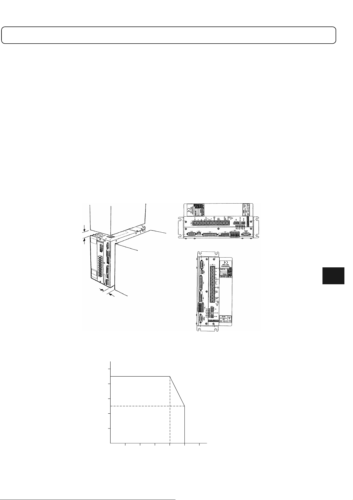
(2) Installation Method
! The standard way of installation is to install the driver on a rack, aligning the top and bottom with the
front panel in the front. Do not put the panel surface into a sideways position or upside down (see the
figure below).
! The driver box employs a natural air ventilation system. Make sure to secure space for ventilation above
and below (25 mm or more) and right and left (25 mm or more) (see the figure below).
! Make sure to use the installation holes (four places) of the upper and lower brackets at installation.
25 mm
Should not be installed in a
sideways position.
Should not b
25 mm
(Note: 1) 2 kW level drivers, but not other types, will have the current characteristics shown in the graph below as a
function of the ambient air temperature during operation. Therefore, it is recommended to use the driver in an
ambient air temperature of 40 °C or less in order to prolong its life.
Current derating curve
50%
45%
40%
30%
25%
20%
Square current duty
10%
installed
upside down.
2
0%
10℃ 20℃ 30℃0℃
Ambient air temperature during operation
40℃ 50℃ 60℃
2-3
Page 25

Chapter 3
Connection and Wiring
3.1 Diagram of Overall Connection
3.2 Cable Specification List
3.3 Connection between Motor and Driver
3.4 Wiring of Motor, AC Power Supply, and Ground Cable
3.5 Wiring of Encoder Cable
3.6 Wiring of Controller Cable
3.7 Wiring of Sensor Brake Terminal
3.8 Wiring of Regenerative Alarm Contact <CNA>
(For 500W Level Drive Only)
3-1
Page 26
3
Connection and Wiring
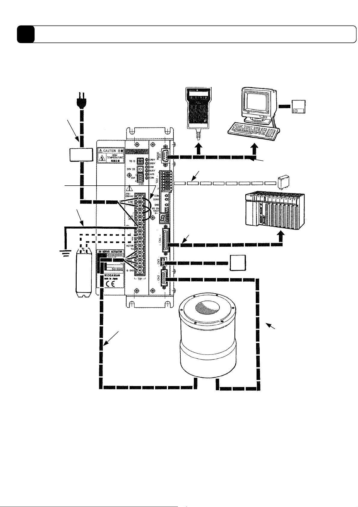
3.1 Diagram of Overall Connection
* Operation display pendant
(including 1.5 m cable)
[PM000AT]
PC
* PC Utility
1) * AC
power supply
cable
7) Jumper
cable
2) Ground cable
<DrvGII> type drive
The figure shows a 2kW level.
Line
*
filter
4) Sensor brake cable
Programmable controller
9) Controller cable
[CP4202G-ooo]
5) * RS232C communication
cable
[CP7675S-020 (for DOSV, 2m)]
[CP7577S-020 (for PC98, 2m)]
8) * Analog monitor card
(with cable connector)
[KC 601A
(Japanese)]
[KC 602A
(English)]
Sensor
* Regenerative resistance
(with lead wire)
3) * Motor cable
Motor part
(DM/DR series)
* Optional parts (see separate wiring section for motor and encoder cables.)
3-2
6) * Encoder cable
Page 27

3.2 Cable Specification List
Cable name Electric cable size Driver Current (A)
AC power supply
1)
cable
Ground cable (power
2)
supply)
3) Motor cable 2.0 mm2 or more, 30 m or less in length TB1
4) Sensor brake cable 0.3 to 0.75 mm
RS232C
5)
communication cable
Encoder resolver
6)
cable
7) Jumper cable 2.0 mm2 or more TB1
8) Analog monitor card
9) Controller cable
* 20A for the A (φ 264mm) and E (φ 205mm) types for both the DM and DR series
15A for the B (φ 160mm) type, and 10A for the DM1004B/1004C motors
2
2.0 mm
2.0 mm
or more, 30 m or less in length TB1
2
or more TB1
2
Dedicated cable is required. CN1
2
0.2mm
twisted pair, batch shielded cable, outer
diameter φ 14 mm or less, 10 m or less in length
Dedicated cable is required. [R7033YB] (cable
with connector)
0.2 to 0.5mm
2
, batch shielded cable, outer
diameter φ 9 mm or less, 3 m or less in length
TB2
CN2
CN3
CN4
*
*
*
Maximum
100 mA DC
*
Maximum
500 mA DC
3
3-3
Page 28
3
Connection and Wiring
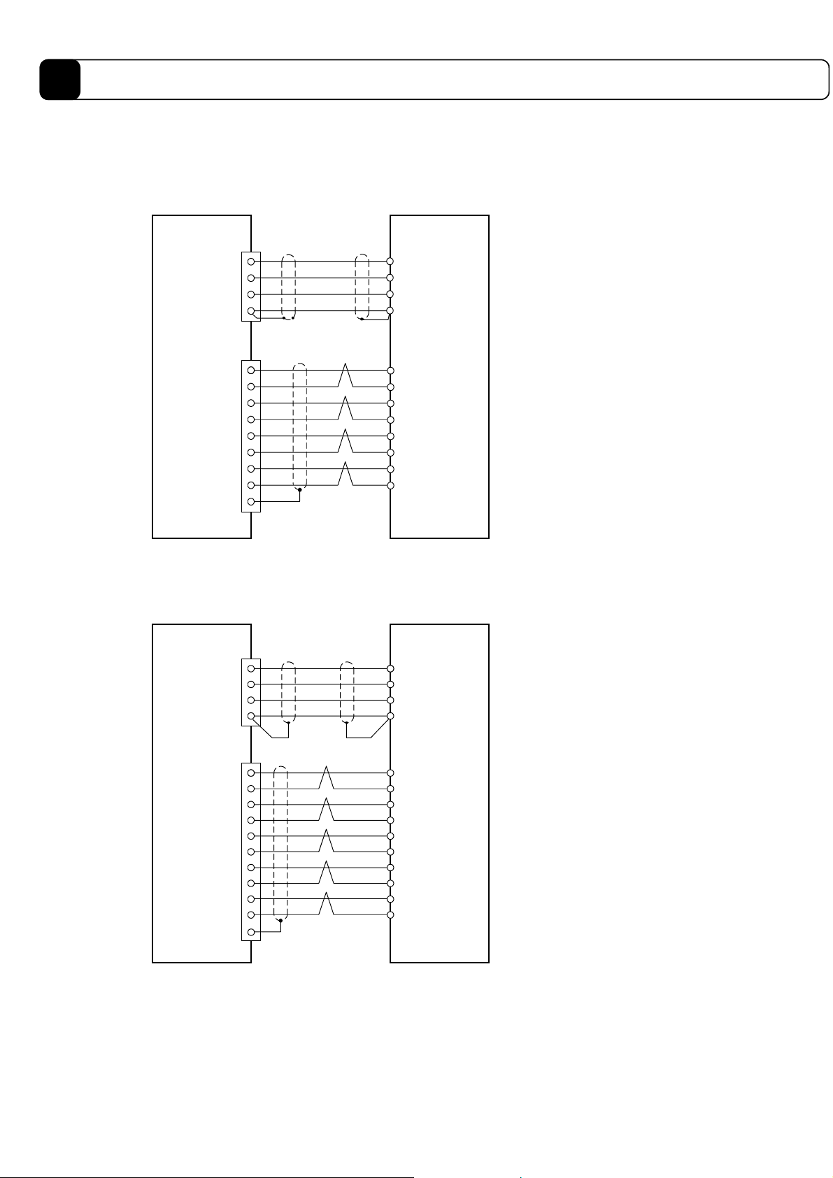
3.3 Connection between Motor and Driver
Note: Shielding should be applied to each wire.
(1) DM Series (DM1004B/1004C) motors
Motor partDriver part
<TB1>
GND
V
A
V
B
V
C
Motor cable
Red
White
Black
Green
<CN2>
+10V/ 1
GND/12
θSIG0/3
GND/14
θSIG1/5
GND/16
ECLK+/ 7
ECLK-/18
Chassis ground
Red
Black
Blue
Blue and white
Brown
Brown and white
Orange
Orange and white
Encoder cable
(2) DM Series motors (models other than the above)
Shielded cable
Motor partDriver part
Red
White
Black
Green
Red
Black
Blue
Blue and white
Brown
Brown and white
Green
Green and white
Orange
Orange and white
<TB1>
GND
<CN2>
+10V/ 1
GND/12
θSIG0/3
GND/14
θSIG1/5
GND/16
ZERO+/ 9
ZERO-/19
ECLK+/ 4
ECLK-/13
Chassis ground
Motor cable
V
A
V
B
V
C
Shielded
cable
Encoder cable
Shielded twisted
pair cable
3-4
Page 29
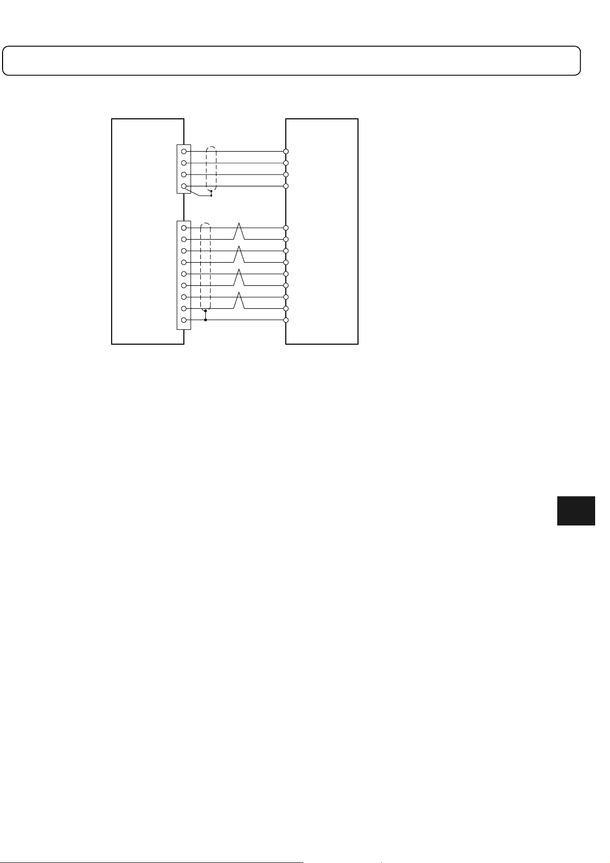
(3) DR Series motors
<TB1>
GND
<CN2>
+S0/ 2
+S180/11
-S0/6
-S180/15
+C0/10
+C180/20
-C0/ 8
-C180/17
Chassis ground
VA
VB
VC
Motor cable
Motor partDriver part
Red
White
Black
Green
Encoder cable
Brown and white
Green and white
Brown
Green
Orange and white
Blue and white
Orange
Blue
Black
3
3-5
Page 30
3
Connection and Wiring
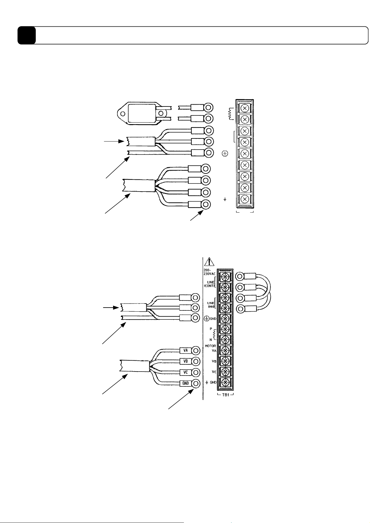
3.4 Wiring of Motor, AC Power Supply, and Ground Cable
(1) For the DM1004B/1004C motors (in connection with a 500W level driver)
* In the case shown, a regenerative resistance is required.
Regenerative
P
resistance*
AC power
supply cable
Ground cable
Motor cable
(Red)
(White)
(Black)
(Green)
Japan Solderless Terminal
type (N1.25-M4)
GND
V
V
V
GND
AC
AC
A
B
C
N
100115VAC
LINE
GND
MOTOR
V
A
V
B
V
C
GND
Driver side
(500W level)
TB1
(2) For other DM/DR series (other than above) (in connection with 2kW level driver)
Power supply
cable
Ground cable
Motor cable
Japan Solderless
Terminal type (N2-M4)
(Red)
(White)
(Black)
(Green)
AC
AC
GND
Jumper
cable
Driver side
(2KW level)
3-6
Page 31

Cable
AC power
supply cable
Motor cable
Specification
DM1004B/1004C Other DM/DR series
!
0.5 mm2 or more, 30 m or less in length
! Clamping torque of terminal: 12[kgf-cm
2
](1.18[N⋅m])
!
2.0 mm2 or more, 30 m or less in length
(terminal screw: M4x0.7)
! Power supply filter, recommended part: Tokin Corporation #LF-200 series
! 0.5 mm
!
Optional cable: CM6000C-
2
or more, 15 m or less in length ! 2.0 mm2 or more, 30 m or less in length
"""
! Optional cable: CM300M-""" or
CM0300R-"""
2
or more (use as thick cable as
Ground cable
!
0.5 mm2 or more (use as thick cable as possible)
!
2.0 mm
possible)
! Third grade ground (ground resistance 100Ω or less)
Jumper wire ! 2.0 mm2 or more
Regenerative
resistance*
For 100V: 80W 60Ω
For 200V: 80W 200Ω
* Only for models with regenerative resistance (500W level)
3
3-7
Page 32

3
Connection and Wiring
3.5 Wiring of Encoder Cable
(1) DM1004B/C motor
Pin #
Signal
name
1 + 10 V 11 - 1 + 10 V 11 - 1 - 11 +S180
2 - 12 GND 2 - 12 GND 2 +S0 12 3
θSIG 0
4 - 14 GND 4 ECLK+ 14 GND 4 - 14 5
θ SIG 1
6 - 16 GND 6 - 16 GND 6 -S0 16 7 ECLK+ 17 - 7 - 17 - 7 - 17 -C180
8 - 18 ECLK- 8 - 18 - 8 -C0 18 9 - 19 - 9 ZERO+ 19 ZERO- 9 - 19 -
10 - 20 - 10 - 20 - 10 +C0 20 +C180
Pin #
Chassis
ground
Signal
name
13 - 3
15 - 5
Shielded
cable
(other than the one described to the left)
Pin #
(2) DM series motor
Signal
name
θSIG 0
θSIG 1
Pin #
13 ECLK- 3 - 13 -
15 - 5 - 15 -S180
Chassis
ground
Signal
name
Shielded
cable
Pin #
(3) DR series motor
Signal
name
Pin #
Chassis
ground
Terminal for <CN2>
2011
Insertion
surface
Made by Honda Tsushin Kogyo
Connector: PCR-S2OF
Housing: PCR-LS20LA1
Chassis ground
(shielded cable)
1
1 32
10
Signal
name
FG
Shielded
cable
Soldering
surface
Electric wire
specification
11 1312
! 0.2 mm
less in length*
2
multiple-core twisted pair batch shielded cable, 30 m or
20
Optional cable
DM series motor
DM1004B/C
(other than the ones
described to the left)
CE7900C-""" CE7900M-""" CE7900R-"""
* Within 10 m only for small-diameter/flat types (DM1004B/C).
DR series motor
3-8
Page 33

3.6 Wiring of Controller Cable
<CN4> terminal
Pin # Signal name Pin # Signal name Pin # Signal name Pin # Signal name
1 COMP1 10 UA_OUT- 19 IN_ERR_RESET 28 IN_FN
2 COMN1 11 DB_OUT+ 20 IN_SERVO 29 IN_PLS_DIRECT
3 OUT_DRDY 12 DB_OUT- 21 IN_MODE_START 30 IN_PACT
4OUT_SRDY 13Z_OUT+ 22IN_ABORT 31 (NC)
5 OUT_BUSY 14 Z_OUT- 23 IN_MODE.0 32 (NC)
6 OUT_XOVL 15 PUA_IN+ 24 IN_MODE.1 33 CRNT_LMT_IN+
7 OUT_OVER 16 PUA_IN- 25 IN_POSW.0 34 CRNT_LMT_IN-
8 OUT_COIN 17 SDB_IN+ 26 IN_POSW.1 35 (NC)
9 UA_OUT+ 18 SDB_IN- 27 IN_GAIN 36 (NC)
Terminal for <CN4>
Made by Honda Tsushin Kogyo
Connector: PCR-S36FS
Housing: PCR-LS36LA
Chassis ground
(shielded cable)
Electric wire
specification
19 36
118
1 32
!
0.2 to 0.5 mm2 or more, multiple-core batch shielded cable, 3 m or
less in length
!
Optional cable: CP4202G-
Insertion surface
Soldering surface
18
36212019
"""
3
3-9
Page 34

3
Connection and Wiring
3.7 Wiring of Sensor Brake Terminal
Pin # Signal name
1COMP0
2XORG
3XOTD
4XOTU
5(NC)
6 XBRKP
7 XBRKN
1) Push down the lever with
a screwdriver.
Electric wire
specification
See the panel surface of the driver for the pin numbers.
<TB2> Made by Sato Parts (ML1900H)
2) Insert the wire deeply.
! 0.3 to 0.75 mm2, electric wire coating with 10 mm of the core
exposed at the tip
! If a twisted wire is used, the diameter of the strand should be
φ 0.18 or larger.
3) Push up the lever
(until you hear the click)
10mm
Example of sensor connection (sensor: EE-SX670 manufactured by Omron)
The recommended sensor logic is B contact.
Set the sensor to OFF when the light is shielded. The sensor described above will be set to OFF when the light is shielded
by the following result.
Signal
name
XORG
XOTD
XOTU
(NC)
XBRKP
XBRKN
Pin #
1COMP0
2
3
4
5
6
7
1
2
3
4
1
2
3
4
1
2
3
4
+
DC power
supply
-
Home position sensor
(-) Over travel
(+) Over travel
COMP0
XORG
XOTD
XOTU
[Electrical specifications]
Input specifications
Rated voltage
Rated input
current
Input
impedance
Operating voltage
(relative to COMP*)
Allowable
leakage current
470Ω
2.7kΩ
12~24VDC (±10%)
4.1 mA/point (at 12 VDC)
8.5 mA/point (at 24 VDC)
3.0kΩ
At OFF: 3.0 VDC or less
At ON: 9.0 VDC or more
OFF is guaranteed at 1.0
mA or less.
Vcc
100kΩ
PS2805
10kΩ
0.01μF
3-10
Page 35

3.8 Wiring of Regenerative Alarm Contact <CNA>
(For 500W Level Drive Only)
This driver (with regenerative terminal) is equipped with a regenerative circuit failure detection circuit. When
connecting the regenerative circuit, build a sequence circuit as shown in the figure below in order to prevent
burnout incidents.
Note: Build a sequence circuit so that it will turn off the power supply at alarm operation.
Driver
MC
LINE
<TB1>
MC
L
N
<CNA>
Made by Phoenix Contact
(plug: MC1, 5/2-ST-5, 08)
Direction of
insertion
ONOFF
MC
MC
Regenerative
<CNA>
Blade point of the driver used
Thickness 0.4mm, width 2.5mm
(clamping torque: 0.22 to 0.25 [N-m]
alarm
250 V AC 0.1 A
30 V DC 1 A
7 mm
3
3-11
Page 36

Chapter 4 Basic Settings for Operating
the Motor
This chapter describes "Basic Settings," which should be used as the
first step in understanding the "motor/driver/PC utility." The information
is provided progressively, focusing on motor tuning, homing operation,
and its setting method.
Make sure to perform the operations described in this chapter as a
preliminary step before commencing device production.
4.1 Procedure (Flowchart)
4.2 Preoperation check
4.3 Installing the PC Utility on the PC
4.3.1 Procedure
4.3.2 Startup
4.4 Preparation
4.4.1 Selecting Communication Port
4.4.2 Selecting Channels
4.4.3 Displaying Communication Strings
4.4.4 Main Menu
4.5 Setting the Status to Servo ON
4.6 Auto-tuning
4.7 Performing Homing Operation
4.8 Performing the Basic Settings of Pulse Commands
4.8.1 About Position Command Pulse Input
4.8.2 Example of Operation
4-1
Page 37

4
Basic Settings for Operating the Motor
4.1 Procedure (Flowchart)
In this section, we will operate the motor according to the procedure below.
START
Preoperation check
Install the PC utility.
Set the status to
"Servo ON."
Auto-tuning
Homing operation
Basic settings of
pulse commands
Check the installation of the motor, wiring etc.
Install the software PC utility on your PC.
Set the status of the motor to "Servo ON."
!
Operation using the PC utility (RS-232C).
Adjust the servo (gain adjustment).
!
Operation using the PC utility (RS-232C).
Perform homing operation.
!
The case where the home position proximity
sensor is input in the driver is explained.
Perform the basic settings required for pulse
input.
Operate (pulse input)
END
Perform the settings and pulse input required for
operation from the user's controller.
4-2
Page 38

4.2 Preoperation check
(1) Items to prepare
• Motor unit/driver/sensor/DC power supply
• PC utility (floppy disk)
• Level block for fixing the motor
• PC (with Windows 95/98/98SE/Me/NT4.0/2000 installed)
• Various cables
(2) Installation and Wiring
Positioning
controller
PC utility (software)
24V DC
power supply
(prepared by customers)
TB 2
DrvGII
type
TB 1
CN 2
driver
CN 1
CN 4
(prepared by customers)
7) RS232C cable
(dedicated)
CP7576(77)S-020
3) Power supply line
1) Level block
(prepared by customers)
6) Sensor wiring
(prepared bycustomers)
Motor part
(main body)
Sensor
Level block
4) Motor cable
CM0300M(R) -ooo
5) Encoder cable
CE7800M(R)-ooo
(3) Items to be checked Check
1) Is the main body fixed on the level block? "
2) Is the motor not interfering with peripherals? "
PC
4
3) Is the power supply line wired properly? (LINE, GND) "
4) Is the motor cable wired properly? (VA, VB, VC. GND) "
5) Is the encoder cable wired properly? "
6) Is the sensor wired properly? "
(Home position, OT sensor: driver (or positioning controller))
7) Is the RS232C cable wired properly? "
8) Is RS-232C operation enabled? "
(Is bit 2 of PSW1 is on?)
9) Is the wiring with the positioning controller done properly? "
(See a connection example on the following page.)
4-3
Page 39

4
Basic Settings for Operating the Motor
Controller
12 to 24 VDC
Photocoupler, contact, etc.
DrvGII (CN4) I/O 24V Specification
01
19
20
21
22
23
24
25
26
27
28
29
30
COMP1
IN_ERR_RESET
IN_SERVO
IN_MODE_START
IN_ABORT
IN_MODE.0
IN_MODE.1
IN_POSW.0
IN_POSW.1
IN_GAIN
IN_FN
IN_PLS_DIRECT
IN_PACT
2.7K
PS2805 or equivalent
Ω
470
Ω
Photocoupler,
contact, etc.
AM26LS31 or equivalent
AM26LS32 or equivalent
LMIT
12 to 24 VDC
+
-
+
-
+
-
+
-
+
-
03
04
05
06
07
08
02
15
16
17
18
09
10
11
12
13
14
33
34
OUT_DRDY
MA8330 or
equivalent
OUT_SRDY
OUT_BUSY
OUT_XOVL
OUT_OVER
OUT_COIN
COMN1
PUA_IN+
PUA_IN-
SDB_IN+
SDB_IN-
UA_OUT+
UA_OUT-
DB_OUT+
DB_OUT-
Z_OUT+
Z_OUT-
CRNT_LMT_IN+
CRNT_LMT_IN-
33
Ω
2AD1820A or
equivalent
91
MA8330 or equivalent
PS2805 or equivalent
TLP115A or equivalent
Ω
AM26LS31 or equivalent
+
-
+
-
+
-
200K
Ω
Ω
200K
-
+
Connect the shield with the shell of
the connector.
4-4
Page 40

Controller
5VDC
7407 or equivalent
DrvGII (CN4) I/O 5V Specification
01
19
COMP1
IN_ERR_RESET
Ω
470
Ω
1K
PS2805 or equivalent
74LS244 or
equivalent
20
21
22
23
24
25
26
27
28
29
30
5VDC
Ω
1K
03
04
IN_SERVO
IN_MODE_START
IN_ABORT
IN_MODE.0
IN_MODE.1
IN_POSW.0
IN_POSW.1
IN_GAIN
IN_FN
IN_PLS_DIRECT
IN_PACT
OUT_DRDY
MA8330 or
equivalent
OUT_SRDY
MA8330 or equivalent
2AD1820A or
equivalent
PS2805 or equivalent
AM26LS31 or equivalent
+
-
+
-
AM26LS32 or equivalent
+
-
+
-
+
-
LMIT
05
06
07
08
02
15
16
17
18
09
10
11
12
13
14
33
34
Connect the shield with the shell of
the connector.
OUT_BUSY
OUT_XOVL
OUT_OVER
OUT_COIN
COMN1
PUA_IN+
PUA_IN-
SDB_IN+
SDB_IN-
UA_OUT+
UA_OUT-
DB_OUT+
DB_OUT-
Z_OUT+
Z_OUT-
CRNT_LMT_IN+
CRNT_LMT_IN-
4
Ω
33
Ω
91
200K
200K
TLP115A or equivalent
AM26LS31 or equivalent
+
-
+
-
+
-
Ω
-
+
Ω
4-5
Page 41

4
Basic Settings for Operating the Motor
4.3 Installing the PC Utility on the PC
4.3.1 Procedure
Installation under Windows 95/98/98SE/Me/NT4.0/2000
The G2 PC utility (hereinafter referred to as the “PC utility”) runs on Windows 95, 98, 98SE, Me,
WindowsNT4.0 and 2000. It can be installed via “Add/Remove Programs” under the “Control Panel” in
Windows. If an older version of the PC utility is present, delete it first and then install the new version.
Display the “Properties of Adding/Removing Programs” dialog box and click “Set Up (1).” Then proceed
according to the instructions displayed on the screen. The PC utility setup program starts up.
Proceed with the setup according to the instructions on the screen. A dialog box for determining the directory in
which to install the PC utility appears (see Figure 4.3.1).
Figure 4.3.1 “Choose Destination Location” dialog box
Click “Browse” to display the “Select Directory” dialog box and select the desired drive and directory. Click
“Next” to display “Select Program Folder” (see Figure 4.3.2).
4-6
Page 42

Figure 4.3.2 “Select Program Folder” dialog box
Select a program folder and click “Next.” The installation begins. Follow the instructions on the screen and
change disks. When the setup is completed, the “Setup Complete” dialog box appear (see Figure 4.3.3).
4
Figure 4.3.3 “Setup Complete” dialog box
To start the program, select “Launch the program file” and click “Finish.” If you do not want to start the program,
just click “Finish.” If you are prompted to restart the computer, simply follow the message and restart it.
Note: Remove the floppy disk before restarting the computer.
4-7
Page 43

4
Basic Settings for Operating the Motor
4.3.2 Startup
1)To start the PC utility, click “Start,” “Program (P),” “YOKOGAWA_E” and then “DrvGII.”
Figure 4.3.4 “Startup”
2) An “Version Information” dialog box is displayed for several seconds and then the PC utility starts up.
Version of PC utility
Figure 4.3.5 “Version Information” dialog box
Figure 4.3.6 After starting up the PC utility
4-8
Page 44

4.4 Preparation
Connect the serial port of the PC with the serial port of the driver with a dedicated cable.
(Do not use any of commercially available cables. Since 5V power is being output from the driver as the power
supply for the operation display pendant, a breakdown may occur in the PC if such cable is used.)
4.4.1
Selecting Communication Port
When you start the PC utility, the “ComPortSelect” dialog box appears in the left side of the screen (see Figure
4.4.1). Change the setting according to the communication port of the connected PC.
Figure 4.4.1 “ComPortSelect” dialog box
Note: Settings made in the “ComPortSelect” dialog box are stored in a file. It is not necessary to make settings
from the next time you start the PC utility. Change the setting as necessary.
4.4.2 Selecting Channels
When you start the PC utility, the “Communication mode” dialog box appears in the upper left corner of the
screen (see Figure 4.4.2). If you are using one driver, select a single channel, and if you are using multiple
drivers, select multi-channel addresses. (See Chapter 6 for how to make setting on the driver side.)
Figure 4.4.2 “Communication mode” dialog box
Note: The settings made in the “Communication mode” dialog box are not stored. When the PC utility is started up,
a single channel is always set.
4
4-9
Page 45

4
Basic Settings for Operating the Motor
4.4.3 Displaying Communication Strings
When you start the PC utility, the “Communication string” dialog box appears in the upper right corner of the
screen. (See Figure 4.4.3.) Any strings that the PC utility sends to the driver as well as any strings received from
the driver are displayed regardless of the menu.
-> [String sent]
<- [String received]
Figure 4.4.3 “Communication string” dialog box
4-10
Page 46

4.4.4 Main Menu
When you start the PC utility, the “MainMenu” dialog box appears (see Figure 4.4.4). See the following chapters
for how to start the actual operation.
Figure 4.4.4 “MainMenu” dialog box
4-11
4
Page 47

4
Basic Settings for Operating the Motor
4.5 Setting the Status to Servo ON
The driver can be put into Servo On status through the following operation.
(1) Click the “I/O Config (I)” button in the “MainMenu” and then the “I/O config (L)” button.
Click the I/O Config (I)
button.
(2) Enable Servo ON. Click the checkmark of “1” under DI and then click the Set (S) button.
Set Servo ON (DI-1) to “no
check.” (Negative setting)
Click the I/O Config
(L) button.
!!!!
Caution
Set button
Make sure to click the “Set” button after finishing the setting (the status will become
Servo ON). Verify that the “S-RDY” LED on the front panel is turned on.
4-12
Page 48

(3) Reset the driver according to the message in the dialog box.
Click OK.
(4) Verify that the driver is reset and the “SRDY” LED on the front panel is turned on.
4-13
4
Page 49

4
Basic Settings for Operating the Motor
4.6 Auto-tuning
The auto-tuning can be performed according to the following procedure.
(1) Checking the rotation direction
Check the rotation direction (CW/CCW) of the motor.
CW CCW
Load
installation
surface
Look carefully from both sides of the load installation surface to check the CW/CCW
Caution
!!!!
(2) Click the “Servo Cntl (S)” button on the “MainMenu.”
movement. When started, the motor operates in the CCW direction. Take extra care to
ensure that there is no mechanical interference with the rotor, which is currently in the
stop position.
Click the Servo Cntl
button
4-14
Page 50

(3) Click Auto Tuning Start (tuning starts).
play
(4) Follow the message on the dialog box and click “OK” to start the auto-tuning operation.
Click the Auto Tuning
Start button
After the auto-tuning is
performed, the set values
!!!!
Caution
are dis
ed.
The rotor rotates a maximum of 30º (seven times of reciprocating operation) in the CW
direction. The operation width varies depending on the velocity rating of the motor.
Take extra care not to cause any mechanical interference around the rotor.
<How to calculate the operation width>
Operation width (degree) = motor velocity rating [rps] x 0.02 x 360
(5) Each parameter setting value is displayed and the auto-tuning is automatically terminated.
4
4-15
Page 51

4
Basic Settings for Operating the Motor
4.7 Performing Homing Operation
A homing operation can be performed according to the following procedure.
(1) Checking the rotation direction
Check the rotation direction (CW/CCW) of the motor.
Load
installation
surface
CW CCW
!!!!
Caution
(2) Check the setting of the homing direction through the PC utility.
Look carefully from both sides of the load installation surface to check the CW/CCW
movement. When started, the motor operates in the CCW direction. Take extra care to
ensure that there is no mechanical interference with the rotor.
Click “Drive” in the Main Menu, then “Homing.”
Click “Drive.”
Click “Homing.”
MainMenu DriveMenu
4-16
Page 52

(3) Set the “homing direction” in the “Homing” dialog box.
1) The current setting values are displayed in the
Setting value box by clicking grid “#20.”
The current setting values for the “homing
related” parameters are displayed.
3) Click the “Set” button.
2) Enter 1 in the Setting Value box.
Make sure to press the return key;
otherwise the entry is not made valid.
!!!!
Caution
The initial value that should be set depends on the homing direction. Enter “#20 = 1” if
the homing direction is CW and “#20 = 0” if it is CCW.
(4) Click the “Start” button to start the homing operation.
Click “Start.”
1) The homing operation finishes automatically after the operation is completed.
In the event of
• The homing operation does not finish, and
!!!!
Caution
2) If a homing abnormality message is displayed, follow the message to adjust the
• The motor does not stop even when the home position sensor is detected,
Click “Abort (A)” to stop the motor, then check “wiring” and “auto-tuning” again.
flag position using the limit value as a guideline. If an error occurs, press “ErrReset”
as well.
4
4-17
Page 53

4
Basic Settings for Operating the Motor
4.8 Performing the Basic Settings of Pulse Commands
4.8.1 About Position Command Pulse Input
Perform input (pulses) required for operation according to the explanation in Section 6.2, “Position Command
Pulse Input” in Chapter 6, “Controller Interface.” Prior to performing pulse input, be sure to perform required
settings according to the explanation in Section 6.1, “Terminal Function.”
The position command value instructed from the controller interface is given to the driver by any pair of the
(PLS, SIGN), (UP, DOWN) and (A, B) signals, which is then reflected in the command unit command value.
Which pair of the signals will be used to give a command is set with the #204 Command pulse type
parameter.
(PLS, SIGN) (UP, DOWN) (A, B)
+ direction - direction + direction - direction + direction - direction
PUA_IN
±
PLS
150ns min
UP
150ns min
A
SDB_IN
±
Caution
3µs min 3µs min
The signal should be H when active
(status for flowing current to the
driver photocoupler).
As for the PLS, it should be L when
normal.
SIGN
DOWN
6µs min
The signal should be H when active
(status for flowing current to the
driver photocoupler).
As for both the UP and DOWN, they
should be L when normal.
B
The signal should be H when active
(status for flowing current to the
driver photocoupler).
300ns min
The position command value instructed from the controller interface can change the weight of a single pulse on
the interface by the input signal “PLS_DIRECT.” When the status of the input signal “PLS_DIRECT” is 0, a
single pulse on the interface becomes the value set with the #207 Simplified scaling weighted data parameter.
While the status of the input signal “PLS_DIRECT” is 1, a single pulse on the interface is independent of the
value set with the #207 Simplified scaling weighted data parameter, and becomes a single pulse inside the
driver.
However, do not change the status of any of the (PLS, SIGN), (UP, DOWN) and (A, B) signals for 2 msec each
before and after switching the input signal “PLS_DIRECT” (off → on, on → off).
PLS_DIRECT
PUA_IN
±
SDB_IN
±
Status 1
Status 0
Unchanged
Unchanged
Unchanged
Unchanged
2 msec
or more
2 msec
or more
4-18
2 msec
or more
2 msec
or more
Page 54

4.8.2 Example of Operation
The following shows an example of operation. Input pulses from the positioning controller according to the
velocity pattern shown below.
Upper surface of the motor
(load installation surface side)
Home position
sensor
Homing
position
The rotor moves 50 degrees away
from the homing position, then
back again.
CW direction -> stops for one
second -> CCW direction -> finish
<Velocity pattern : Example of operation>
Velocity
[mm/sec]
50
Moving distance
(positive direction)
50 degrees
0
50
Setting value of
acceleration time
Setting value of
deceleration time
Stop time
1.0sec
Moving distance
(negative direction)
Setting value of
acceleration time
50 degrees
deceleration time
4
Time
[sec]
Setting value of
4-19
Page 55

Chapter 5
Functions
5.1 Parameters and Monitors
5.1.1 General Parameters
5.1.2 Mechanical Setting Parameters
5.1.3 Monitors
5.2 Operation Functions
5.2.1 Jog Move
5.2.2 Test Operation
5.2.3 Auto-Tuning Operation
5.2.4 Homing Move
5.2.5 Mechanical Setting Mode
5.3 Coordinate System
5.3.1 Coordinate System
5.3.2 Switching Position Command Pulse Weights
5.4 Control System
5.4.1 Velocity Control Part
5.4.2 Position Control Part
5.4.3 Feed Forward
5.4.4 Servo Stiffness Parameter
5.5 Acceleration/Deceleration Function
5.5.1 Velocity Override Function
5.5.2 Velocity Profile
5.6 Other Functions
5.6.1 Settling Wait, Position Settling Status, and Positioning Status
5.6.2 Velocity Monitor and Analog Monitor
5.6.3 Brake Signal
5.7 Special Parameter Processing
5.7.1 Internal Generation of Parameter Initial Values
5.7.2 Limiting and Checking Maximum Velocity When Changing Simplified Scaling
Weighted Data and Maximum Velocity Parameters
5.7.3 Auto Conversion and Clear Functions When Changing Simplified Scaling
Weighted Data
5.7.4 Limiting the Maximum Parameter Values
5-1
Page 56

5
Functions
5.1 Parameters and Monitors
The group of variables expressed by #*** is called parameters and monitors. Parameters/monitors are
classified according to their numbers as follows.
Parameter No. Parameter type Backup Comments
0 to 199 General parameters Stored Always possible to read and write.
200 to 299
300 to 399 Monitors -
By expressing all parameters/monitors by #***, their values can be referenced (read). It is also possible to
change (write) the values within the range allowed for each parameter/monitor.
5.1.1 General Parameters
These parameters can be read and written at all times and an operational meaning is assigned to each. The details
of each parameter will be explained separately.
Note that these parameters are stored in the driver; they will not be deleted even if the power is turned off.
5.1.2 Mechanical Setting Parameters
Mechanical setting
parameters
Stored
Reading is always possible, but writing is possible only
when operating in mechanical setting mode.
Read only. Reading is always possible, but writing is not
possible at any time.
It is always possible to read these parameters, but writing is possible only when operating in mechanical setting
mode. These parameters are set only once when the device is started up. An operational meaning is assigned to
each. The details of each parameter will be explained separately.
Note that these parameters are stored in the driver; they will not be deleted even if the power is turned off.
Note: If these parameters are changed during execution in mechanical setting mode, the changes made to the
values will not be reflected until the power is turned on again. Therefore, please note that if you try to read a
parameter value after you change the parameter, the value before the change is read until you turn the
power off and on again.
5.1.3 Monitors
These variables are used to display the driver's status. Only reading is allowed at all times and each has an
operational meaning. The details of each parameter will be explained separately.
5-2
Page 57

5.2 Operation Functions
Idle status Controller interface position command follow-up
Jog move
Test operationOperating status
Auto-tuning operation
Homing move
Mechanical setting mode
The status in which no operation is performed is called the idle status; jog moves can be performed in this
status. If no jog move is being performed in the idle status, the driver follows the position command from the
controller interface.
This driver is equipped with the operation functions listed below. Use them as needed.
The start, end, and stop actions of these operations can be controlled from either the controller interface side or
the RS232C interface side. Refer to the related chapters (Chapter 6, "Controller Interface" and Chapter 7,
"RS232C Interface") for operation methods.
The methods used to end each operation can be classified into three categories: the self-end type that ends
automatically when the operation is complete, the non-self-end type that cannot end the action by itself, and the
non-end type that cannot be stopped once started. An appropriate end or stop action must be performed for each
type.
Operation
No.
0 Test operation
1
2 (Reserved)
3 Homing move
4 to 14 (Reserved)
15
Name Comment Ending type
Generates a 2.5Hz square wave position command signal for
adjustment of the control part.
Auto-tuning
operation
Mechanical
setting mode
Makes the rotor oscillate, measures load inertia and load mass, and
sets the parameters for the control part automatically.
Finds the home position using the hardware over-travel signal,
homing sensor, and motor Zero signal to establish the coordinate
system.
Special mode for changing mechanical setting parameters. Non-end
5.2.1 Jog Move
The rotor can be moved in the positive (+) or negative (-) direction by issuing a jog move command while in idle
status.
There are three types of jog move commands: (+) direction move, (-) direction move, and stop. Refer to the
sections about the RS232C interface and PLC interface for how to issue a command.
The move can only be trapezoidal but it is possible to set the acceleration and deceleration profile. In addition,
the velocity override does function in real time. The velocity in the jog move is determined by the value in the
#10 Jog Velocity parameter.
If operation is started while the jog move is in progress, the operation is executed as soon as the jog move stops.
The settling wait function is not performed at the end of the jog move.
[Related parameter]
Non-self-end
Self-end
Self-end
5
#10 Jog velocity
5-3
Page 58

5
Functions
5.2.2 Test Operation
This operation generates a 2.5Hz square wave and uses it as position command signal for adjustment of the
control part. Set the analog monitor to test operation response to measure the response waveform on the
oscilloscope.
The position feed forward, velocity feed forward, and acceleration feed forward are set to 0 internally during the
test operation.
The settling wait function is not performed at the end of the test operation.
[Related parameters]
#31 Operation width under testing mode
#50 Position control bandwidth 1
#48 Position control bandwidth 2
#51 Velocity control bandwidth 1
#49 Velocity control bandwidth 2
#53 Position integral limiting value
#70 Analog monitor selection
#72 Test operation monitoring gain (analog monitor)
• Obtain the fastest possible rise time of the response waveform and make adjustments so that
!!!!
Caution
• The closer the position control bandwidth and velocity control bandwidth are, the more the waveform
• If the inertia and weight of the load are large, the oscillations may be eliminated by setting the
overshoot will not occur.
will oscillate.
position integral limiting value to a small value.
Increase the position control bandwidth.
Make adjustments until this waveform
is reached
If the velocity control bandwidth cannot
be increased any further, the position
control bandwidth should be decreased
5.2.3 Auto-Tuning Operation
This operation makes the rotor oscillate, measures the inertia and weight of the load, and automatically sets the
parameters for the control part.
It accelerates/decelerates with half the rated torque and rated thrust of the motor, and measures the inertia and
weight of the load from the velocity changes at that time. The result of the measurement is written to the #155
Load inertia/load mass parameter.
From the measured inertia and weight of the load, it adjusts the position control bandwidth, velocity control
bandwidth, and position integral limiting value according to the setting value of the #38 Servo stiffness
settings parameter. For the position control bandwidth and the velocity control bandwidth, the results are
reflected in the parameters on the side selected by the controller interface (see Section 6.5.2, “Position Control
Bandwidth Selection FN” and Section 6.5.3, “Velocity Control Bandwidth Selection GAIN). It does not adjust
position feed forward, velocity feed forward, and acceleration feed forward.
The settling wait function is not performed at the end of the auto-tuning operation.
[Related parameters] [Auto-set parameters]
#32 Operation width under Auto-tuning
#33 Maximum deceleration under Auto-tuning
#34 Initializing the deceleration time while under Auto-
tuning
#37 Auto-tuning repeat count
#38 Servo stiffness settings
#50 Position control bandwidth 1
#48 Position control bandwidth 2
#51 Velocity control bandwidth 1
#49 Velocity control bandwidth 2
#53 Position integral limiting value
#155 Load inertia/load mass
5-4
Page 59

5.2.4 Homing Move
In this operation the rotor is moved according to a preset home position search method in order to establish a
coordinate system. After first moving to the home position determined by the proximity signal and motor Zero
signal, it continues to move an amount further given in the #29 Offset distance from the Home position
parameter's setting value. It then sets the drive coordinate command value to the value set in the #30 Homing
complete operation command value parameter.
There are two ways to generate motor Zero signals (hardware and software Zero signals). The method used
varies depending on the motor. See the explanation given below.
The homing operation is processed in the following order.
The move can only be trapezoidal but it is possible to set the acceleration and deceleration profile. In addition,
the velocity override does function in real time.
The settling wait function is performed at each point during the homing operation.
[Related parameters]
#11 Over-travel search velocity during a homing move
#12 Homing operation: Home sensor proximity signal
search velocity
#13 Homing operation: Home sensing feed velocity 1
#15 Homing operation: Origin position offset feed velocity
#20 Homing direction
#21 Enable/Disable the over-travel signal under the
homing mode
#25 Homing operation: Origin inside selection
#26 Enabling the proximity signal during OT search under
the homing mode
#27 Enabling the homing flag position error
#29 Offset distance from the Home position
#30 Homing complete operation command value
#202 Coordinates (+) direction setting
[Hardware Zero signal]
Applicable motor:
DYNASERV
DMA and DMB series
[Software Zero signal]
Applicable motor:
DYNASERV
Flat motor (DM1004B)
Small-diameter motor (DM1004C)
Standard DRA, DRB and DRE series
High-speed DRB and DRE series
(1) OT search move
The rotor moves until it finds an over-travel (OT) signal in the opposite side of the homing direction and in the
opposite direction of homing direction. It is executed only when the OT signal search move is enabled in #21
Enable/Disable the over-travel signal under the homing mode parameter.
If the proximity signal during OT search move is enabled in the #26 Enabling the proximity signal during OT
search under the homing mode parameter, and an home position proximity signal is detected during an OT
search move, the rotor stops the OT search move, and then proceeds to (2) or (3) below.
The moving velocity is set to the value in #11 Over-travel search velocity during a homing move parameter.
(2) Homing search move
The rotor moves until it finds a homing sensor in the homing direction.
The moving velocity is set to the value in #12 Homing operation: Home sensor proximity signal search
velocity parameter.
(3) Moving to outside of home position proximity area
This is executed only if #25 = 1. If #202 = 1, the rotor moves in (+) direction until it leaves the home position
proximity area. If #202 = 0, the rotor moves in (-) direction until it leaves the home position proximity area.
The moving velocity is set to the value in the #13 Homing operation: Home sensing feed velocity 1
parameter.
5-5
5
Page 60

5
Functions
(4) First home sensing move
With the #25 Homing operation: Origin inside selection parameter, it is possible to select and set either the
inside Zero signal or outside Zero signal of the home position proximity signal as the home position. If #25 = 1,
the inside Zero signal is set as the home position; if #25 = 0, the outside Zero signal is set as the home position.
If #202 = 1, the rotor moves to search the home position proximity signal in (-) direction. If #25 = 1, the rotor
recognizes the first Zero signal edge as the home position upon entering the area, and then stops. If #25 = 0, the
rotor recognizes the first Zero signal edge as the home position upon leaving the area, and then stops.
If #202 = 0, the rotor moves to search the home position proximity signal in (+) direction. If #25 = 1, the rotor
recognizes the first Zero signal edge as the home position upon entering the area, and then stops. If #25 = 0, the
rotor recognizes the first Zero signal edge as the home position upon leaving the area, and then stops.
The moving velocity is set to the value in the #13 Homing operation: Home sensing feed velocity 1
parameter.
(5) Second home sensing move
The second home sensing move is executed in two steps.
1) Preparation move
The rotor moves as far as diametrically opposite the Zero signal edge in the opposite direction of the Zero
signal edge search direction that was used in the first home sensing move.
The moving velocity is set to the value in the #13 Homing operation: Home sensing feed velocity 1
parameter.
2) Zero signal edge search move
The rotor moves until it finds the Zero signal edge in the Zero signal edge search direction that was used in
the first home sensing move.
The moving velocity is set to the value in the #13 Homing operation: Home sensing feed velocity 1
parameter.
(6) Home position move
The home position is moved to the detected Zero signal edge position. Motors that use software Zero signals
further perform a second corrective move.
The moving velocity is determined internally by the driver.
(7) Home position offset move
The home position is moved for the distance given by the value set in #29 Offset distance from the Home
position parameter, after which the operation coordination command value is set to the value given in #30
Homing complete operation command value parameter.
The moving velocity is set to the value in #15 Homing operation: Origin position offset feed velocity
parameter.
For the homing move to be completed normally, the distance between the home position proximity area and the
Zero signal edge must be within a specific range based on the value of #358 Z-phase signal pulse interval
monitor. The reference value differs depending on the method by which the Zero signal (hardware or software
Zero signal) is generated.
At the first home sensing move, the distance to the first Zero signal edge after passing through the home position
proximity area (pulse amount) has been measured and written in #318 Homing operation: The measured
value monitor. If this value does not satisfy the equations below, an error or warning will occur. In that case, the
home position proximity dog should be adjusted and the homing move should be performed again. Repeat these
steps until the operation is completed normally.
5-6
Page 61

[Hardware zero signal type]
0.05*#358 value
0.1 *#358 value
0.7 *#358 value
0.75*#358 value
[Software zero signal type]
0.05*#358 value
0.1 *#358 value
0.4 *#358 value
0.45*#358 value
≦#
≦#
<#
<#
≦#
≦#
<#
<#
318 value
#
318 value
318 value
318 value
318 value error
318 value
#
318 value
318 value
318 value
318 value error
0.05*#358 value error
<
0.1 *#358 value warning
<
0.7 *#358 value normal
≦
0.75*#358 value warning
≦
0.05*#358 value error
<
0.1 *#358 value warning
<
0.4 *#358 value normal
≦
0.45*#358 value warning
≦
5-7
5
Page 62

5
Functions
- Operation example 1 -
(2)
(4)
(+) direction
←
(4)
- Operation example 2 -
(1)
(4)
(+) direction
←
- Operation example 3 -
(4)
(7)
(7)
(5)-2
(5)-2
(5)-2
(3)
(5)-1
(6)
Home position
proximity signal
Zero signal
(3)
(5)-1
(6)
(3)
(5)-1
(6)
Home position
proximity signal
Zero signal
(3)
(5)-1
(6)
Home position
proximity signal
Zero signal
Homing from
outside of the
proximity area
Homing from
outside of the
proximity area
(2)
#20 = 0 Homing direction (-) direction
#21 = 0 Enable/disable the over-travel Not used
#25 = 1 Homing operation: Inside
#26 = 0 Enabling the proximity signal Invalid
#29 = 0 Offset distance from the Home 0
#202 = 1 Coordinate (+) direction setting
#20 = 0 Homing direction (+) direction
#21 = 0 Enable/disable the over-travel Used
#25 = 1 Homing operation: Inside
#26 = 0 Enabling the proximity signal Invalid
#29 = positive value
#202 = 1 Coordinate (+) direction setting
#20 = 0 Homing direction (-) direction
#21 = 0 Enable/disable the over-travel Not used
#25 = 1 Homing operation: Inside
#26 = 0 Enabling the proximity signal Invalid
#29 = negative value
#202 = 1 Coordinate (+) direction setting
(+) direction
signal under the homing mode
Origin inside selection
during OT search under
the homing mode
position
(Initial value setting)
signal under the homing mode
Origin inside selection
during OT search under
the homing mode
Offset distance from the Home
position
(2)
(-) direction over
travel signal
signal under the homing mode
Origin inside selection
during OT search under
the homing mode
Offset distance from the Home
position
→
- Operation example 4 -
(2)
(+) direction
←
(4)
(3)
(5)-2
Home position
proximity signal
Zero signal inside Zero signal outside
(5)-1
(6)
#20 = 0 Homing direction (-) direction
#21 = 0 Enable/disable the over-travel Not used
signal under the homing mode
#25 = 0 Homing operation: Outside
Origin inside selection
#26 = 0 Enabling the proximity signal Invalid
during OT search under
the homing mode
#29 = 0 Offset distance from the Home 0
position
#202 = 1 Coordinate (+) direction setting
5-8
Page 63

5.2.5 Mechanical Setting Mode
This is a special mode for changing parameters related to the mechanical settings. Parameters #200 to #299 can
be changed only when this operation is being executed. In addition, once started, this operation cannot be
stopped. After you finish changing the necessary parameters, turn the power to the driver off and on again.
Note that if you change these parameters, the changed values are not reflected until after the power is turned on
again. Therefore, please note that if you try to read a parameter value after you change the parameter, the value
before the change is read until you turn the power off and on again.
5.3 Coordinate System
5.3.1 Coordinate System
The driver controls the position of the motor by three coordinate systems with different units: a command unit
coordinate system, and a pulse coordinate system.
The pulse coordinate system manages the coordinate values in units of pulses that can be detected by the encoder
resolver. The position control part of the driver controls the motor based on these coordinate values. It has a
command value and a current value, and they are always updated and displayed in the #320 Pulse position
command value monitor and #321 Pulse position current value monitor, respectively.
The command unit coordinate system manages coordinate values in the amount of pulses on the controller
interface. The position command values that occur in the driver itself (test operation, auto-tuning operation,
homing operation, jog move operation) are also processed based on these coordinate values. The command unit
coordinate system has command values and current values, each of which are constantly updated and displayed
in the #323 Command unit command value monitor and the #370 Command unit current value monitor,
respectively.
5.3.2 Switching Position Command Pulse Weights
The position command value instructed from the controller interface is given to the driver by any pair of the
(PLS, SIGN), (UP, DOWN) and (A, B) signals, which is then reflected in the command unit command value.
Normally, the pulse position command value inside the driver for a single pulse on the controller interface
becomes the value set with the #207 Simplified scaling weighted data parameter. For example, if the setting
value is 4, a single pulse on the controller interface will be equivalent to 4 pulses inside the driver.
In addition, the command unit current value is output from the driver by either the (UP, DOWN) or (A, B) signal.
The pulse position current value inside the driver for a single pulse on the controller interface always becomes
the value set with the #207 Simplified scaling weighted data parameter. For example, if the setting value is 4,
a single pulse on the controller interface will be equivalent to 4 pulses inside the driver.
While the input signal “PLS_DIRECT” is on, the position command value instructed from the controller
interface is independent of the value set with the #207 Simplified scaling weighted data parameter; a single
pulse on the controller interface will be a single pulse inside the driver, instead. However, do not change the
status of any of the (PLS, SIGN), (UP, DOWN) and (A, B) signals for 2 msec each before and after switching the
input signal “PLS_DIRECT” (off → on, on → off).
[Related parameters]
#207 Simplified scaling weighted data
5
5-9
Page 64

5
Functions
5.4 Control System
In this section, the position control part, velocity control part, and feed forward of the driver are explained.
The block diagram of the control system is shown below.
←
#387
Motor linear
coordinate
command
value
Feed forward
Acceleration
feed forward
Velocity feed
forward
Position feed
forward
+
-
+
-
#389
Motor linear
coordinate
deviation
#56
#55
Integral main
#54
+
#59
Position
current
value filter
current value after filtering
switch
Proportio
nal
control
Integral
control
Differential
feedback
#384
Motor linear coordinate
Position
control part
#50
#48
#203
+
limiting value
-
control part
#364
Velocity
command value
after filtering
(digital)
#363
Velocity value
(digital)
+
+
#53
Position
integral
#388
Motor linear coordinate
current position
Velocity
command
+
Velocity current
after filtering
#321
Pulse position current value
#320
Pulse position command value
#322
Pulse position deviation
Velocity
#221
filter
#366
value
+
-
#365
Velocity error
(digital)
#361←#51
#49
Velocity
proportional
gain
Velocity
feedback filter
#219,#220
#152
+
First order delay
+
compensation
device setting
#365
Velocity current value
#153,#154
Notch
filter 2Ch
#155
#360
Motor
mechanical
system
Velocity
sensor
#356
#355
Position
sensor
Motor
position
5-10
Page 65

5.4.1 Velocity Control Part
For the velocity control bandwidth, either the value set with the #51 Velocity control bandwidth 1 parameter or
the #49 Velocity control bandwidth 2 parameter is selected, according to the status of the controller interface
input signal IN_GAIN. The selected value is displayed in the #376 Velocity control bandwidth monitor.
The velocity control part calculates the #361 Velocity proportional gain monitor value from the #155 Load
inertia/load mass parameter value, which is either measured and set by an auto-tuning operation or entered
directly as a numerical value, according to the velocity control bandwidth value. During this process, the
frequency characteristics of neither the velocity feedback filter nor the notch filter are considered but only the
frequency characteristic of the first order delay compensation device is considered to calculate the velocity
proportional gain.
The first order compensation device can be set in four ways via the #152 First order delay compensation
device setting parameter. The first order delay compensation device has the effect that it improves the gain
characteristics of the velocity control part. The frequency characteristics for each setting of the first order
compensation device is shown below. Note that there is no frequency dependency when the first order
compensation is not set.
There are two channels available for the notch filter (optional). The central frequency value can be set
independently for each channel via the #153 Notch filter: Frequency selection 1 and #154 Notch filter:
Frequency selection 2 parameters. The notch filter has the effect that it improves the gain characteristics of
mechanical systems that tend to resonate.
The velocity feedback filter can be enabled or disabled by setting the #219 Enable/Disable velocity feedback
filter parameter. When enabled, the filter bandwidth can be set in the #220 Velocity feedback filter bandwidth
parameter. The velocity feedback filter is effective in eliminating noise at motor operation, but with a small
bandwidth the velocity control part tends to oscillate.
The filter bandwidth of the velocity command filter can be set in the #221 Velocity command filter bandwidth
parameter. The velocity command filter helps achieving smoother acceleration/deceleration, but with a small
bandwidth the position control part tends to oscillate.
[Related parameters]
#51 Velocity control bandwidth
#152 First order delay compensation device setting
#153 Notch filter: Frequency selection 1
#154 Notch filter: Frequency selection 2
#155 Load inertia/load mass
#219 Enable/Disable velocity feedback filter
#220 Velocity feedback filter bandwidth
#221 Velocity command filter bandwidth
20Hz/80Hz
30Hz/120Hz
40Hz/160Hz
20Hz/80Hz
30Hz/120Hz
40Hz/160Hz
[Frequency characteristics of the first order
delay compensation device]
5
5-11
Page 66

5
Functions
5.4.2 Position Control Part
For the position control bandwidth, either the value set with the #50 Position control bandwidth 1 parameter or
the #48 Position control bandwidth 2 parameter is selected, according to the status of the controller interface
input signal IN_FN. The selected value is displayed in the #375 Position control bandwidth monitor.
The position control part calculates the proportional control gain, integral control gain, and differential feedback
gain, according to the position control bandwidth value.
The position integral limiter set by the #53 Position integral limiting value parameter is effective in suppressing
integrator windup due to motor torque and thrust saturation. Decrease the value in order to suppress windup
further. On the other hand, if you set the value too small, the motor torque and thrust are limited; set a value as
large as possible in the range where windup does not occur.
The integral operation of the position control part can also be set either to be active (allow) or inactive (prohibit).
If you clamp the motor with an external device when the motor is stopped, the integral operation should be
prohibited after clamping in order to prevent overloading the controller. Refer to Chapter 6 “Controller
Interface” and Chaper 7 “RS232C Interface” for details of the operation.
The position current value filter outputs the result obtained by filtering the position current value to the #384
Motor linear coordinate current value after filtering monitor. The filter bandwidth is set with the #59
Position current value filter frequency parameter. The position control part outputs a value before or after
being filtered to the #321 Pulse position current value monitor, according to the setting status of the #203
Using position current value filter parameter. It also calculates the value of the #322 Pulse position
deviation monitor, using the current value before or after being filtered, according to the setting status of the
#203 parameter.
[Related parameters]
#50 Position control bandwidth 1
#48 Position control bandwidth 2
#53 Position integral limiting value
#59 Position deviation filter frequency
#203 Using position current value filter
5.4.3 Feed Forward
Three types of feed forward functions are available: position feed forward, velocity feed forward, and
acceleration feed forward. Feed forward function is effective for quick positioning.
The position feed forward can be set by percentage in the #54 Position feed forward percentage parameter.
The position feed forward makes the position deviation at equal velocity move smaller and helps to achieve a
smooth settling at acceleration/deceleration.
The velocity feed forward can be set by percentage in the #55 Velocity feed forward percentage parameter.
The acceleration feed forward calculates the acceleration feed forward gain from the #155 Load inertia/load
mass parameter values, which are measured and set by the auto-tuning operation or set directly by numerical
values, based on the #56 Acceleration feed forward gain parameter. #56 parameter is given as a percentage.
[Related parameters]
#54 Position feed forward percentage
#55 Velocity feed forward percentage
#56 Acceleration feed forward percentage
#155 Load inertia/load mass
5-12
Page 67

5.4.4 Servo Stiffness Parameter
The #38 Servo stiffness settings parameter is for general settings for the control system. The control
parameters are set based on this parameter after measuring the load inertia/load mass in the auto-tuning
operation.
If #38 is changed, either one of the position control bandwidth parameters (#50, #48) selected by IN_FN and
either one of the velocity control bandwidth parameters (#51, #49) selected by IN_GAIN are set. In addition, the
gain of the control system is set automatically, and the position integral limiting value parameter (#53) is also
automatically set to the minimum position integral limiting value that can generate the maximum torque and the
maximum thrust in the motor lock status. It is not necessary to set parameters related to feed forward and filters
again.
[Related parameters]
#38 Servo stiffness settings
#50 Position control bandwidth 1
#48 Position control bandwidth 2
#51 Velocity control bandwidth 1
#49 Velocity control bandwidth 2
#53 Position integral limiting value
5-13
5
Page 68

5
Functions
5.5 Acceleration/Deceleration Function
This driver performs trapezoidal moves during jog moves and homing moves, and uses the
acceleration/deceleration function described in this section.
In addition, it has a velocity override function for switching velocity during a move, which works in real time
even during the move (real time velocity override function).
The maximum velocity of the motor is defined in #213 Maximum velocity, but is limited by the maximum
velocity defined within the driver. The limited value is displayed in the #357 Maximum velocity monitor.
5.5.1 Velocity Override Function
The velocity override value is set with the #16 Velocity override percentage 1 parameter.
The velocity override value can be set in increments of 0.01% from 0 to 200%. Please note that if a value greater
than 100% is set, the velocity during the move may exceed the maximum velocity, which may cause an error.
How the velocity override is applied differs for the trapezoidal move and cam profile move.
[Related parameters]
#16 Velocity override percentage 1
5-14
Page 69

5.5.2 Velocity Profile
In a trapezoidal motion, the acceleration of the moving part follows the acceleration type set by the #4 Selecting
acceleration type parameter until it reaches the feed velocity. Hereafter, the move is continued with the feed
velocity, then decelerates and stops according to the deceleration type set by the #5 Selecting deceleration
type parameter. The feed velocity varies depending on the operation.
The acceleration and deceleration types can be selected separately. There are two options for acceleration and
deceleration: a constant acceleration type and an S-shaped type (where the acceleration/deceleration follows
a second order spline). Generally, the S-shaped type can limit vibrations in the machine better, but the peak
torque or peak thrust at acceleration/deceleration become greater and a correspondingly larger motor torque or
motor thrust will be required.
The acceleration/deceleration time can also be selected separately. The values of the #7 Acceleration time
during a trapezoidal move and #8 Deceleration time during a trapezoidal move parameters are set to
values equivalent to the maximum velocity shown in the #357 Maximum velocity monitor. The actual
acceleration/deceleration time becomes the value obtained by multiplying the maximum velocity by the velocity
ratio during a trapezoidal move. By doing so, the same acceleration can be maintained without changing #7 and
#8 even when the feed velocity setting is changed.
Waiting for trigger Waiting for trigger
200ms/div
[Constant
acceleration]
#7 Acceleration time during a
trapezoidal move
Actual acceleration time
NORM:5kS/s
Maximum velocity
Feeding Velocity
Maximum velocity
Feeding Velocity
#8 Deceleration time during a
trapezoidal move
Actual deceleration time
200ms/div
NORM:5kS/s
[S-shaped]
Waiting for trigger
#7 Acceleration time during a
trapezoidal move
Actual acceleration time
[Acceleration] [Deceleration]
Waiting for trigger
200ms/div
NORM:5kS/s
#8 Deceleration time during a
trapezoidal move
Maximum velocity
Feeding Velocity
Maximum velocity
Feeding Velocity
Actual deceleration time
[Acceleration] [Deceleration]
200ms/div
NORM:5kS/s
5
5-15
Page 70

5
Functions
The feed velocity during a move becomes the commanded velocity multiplied by the velocity override value.
If the velocity override value is changed during a move, the moving part is accelerated at the same acceleration
profile and acceleration as the normal acceleration time when the velocity override value is increased. In the
same way, the moving part is decelerated at the same deceleration profile and deceleration as the normal
deceleration time when the velocity override value is decreased.
Waiting for trigger
500ms/div
NORM:2kS/s
150%
100%
0%
[Acceleration: s-shaped, deceleration: constant acceleration]
[Related parameters]
#3 Selecting the type of cam profile move
#4 Selecting the acceleration type
#5 Selecting the deceleration type
#7 Acceleration time during a trapezoidal move
#8 Deceleration time during a trapezoidal move
Waiting for trigger
150%
100%
500ms/div
NORM:2kS/s
0%
5-16
Page 71

5.6 Other Functions
5.6.1 Settling Wait, Position Settling Status, and Positioning Status
Position settling status refers to the status where the position deviation (pulse coordinates) is within the
specified range in the pulse coordinate system. The specified range is set with the #58 Position settling pulse
width 1, #45 Position settling pulse width 2, #46 Position settling pulse width 3, and #47 Position settling
pulse width 4 parameters in pulse units, which are selected by the controller interface input signal
IN_POSW[1..0]. The selected value is then displayed in the #377 Position settling width monitor. The #322
Pulse position deviation monitor is used for the position deviation to be evaluated. The position settling status
is set when the absolute value of position deviation becomes shorter than the position settling width for the
duration set with the #61 Position settling signal chattering processing count parameter. The check cycle is
2 msec. If chattering occurs in a “COIN” due to an overshoot during position settling, depending on the load
status, the settling condition can be obtained without fail by increasing the chattering processing count. The
position settling status is displayed in the #328 Position settling status monitor. It is also displayed with the
“COIN” LED on the front panel: it turns on to indicate the position settling status. Furthermore, it is output to the
“COIN” of the CN3 analog monitor interface by a digital signal.
Positioning status is the status where an acceleration/deceleration command for a move is completed and in
position settling status. The positioning settling status is displayed in the #329 Positioning status monitor.
Settling wait is a function invoked to keep on waiting until the positioning status is reached at the end of a move.
Settling wait can be made in two ways depending on the operation: never perform settling wait or always
perform settling wait.
Operation
Never perform Jog move, test operation, auto-tuning operation
Always perform Homing move
[Related parameters]
#58 Positioning settling width 1
#45 Positioning settling width 2
#46 Positioning settling width 3
#47 Positioning settling width 4
#61 Position setting signal chattering processing count
#203 Using position current value filter
5
5-17
Page 72

5
Functions
5.6.2 Velocity Monitor and Analog Monitor
The current velocity value of the motor is output to “VEL” of the CN3 analog monitor interface as the velocity
monitor signal.
The signal sensitivity of the velocity monitor ([V/rps] in case of a rotating DYNASERV motor and [V/mps] in
case of a linear LINEARSERV motor) can be obtained by multiplying the #69 Velocity monitor gain parameter
setting by the #356 Digital velocity sensitivity monitor value. For example, if the setting of #69 is 6.55V/8192
digits and the value of #356 is 4800 [digit/rps] in a rotating motor, the signal sensitivity of the velocity monitor is
3.84 [V/rps]. The velocity monitor signal is output in the range of ± 6.55V.
Moreover, it is possible to output only the AC element of the current velocity value of the motor via the setting
of the #75 Velocity monitor selection parameter.
One of the data items below is output to “AMON” of the CN3 analog monitor interface as an analog monitor
signal.
The content of the analog monitor can be selected by the #70 Analog monitor selection parameter. Depending
on the selected content, the signal sensitivity is adjusted using the corresponding monitor gains #71 to 74. The
analog monitor signals are output in the range of ± 6.55V.
Analog monitor selection Unit Monitor gain
Position deviation Pulse #71 Positioning error monitoring gain (Analog monitor)
Test operation response Pulse #72 Test operation monitoring gain (Analog monitor)
Position command value Pulse
Position current value Pulse
Position command differential value pps
Position current differential value pps
#73 Position monitoring gain (Analog monitor)
#74 Position differential value monitor gain (Analog
monitor)
[Related parameters]
#69 Velocity monitoring gain
#70 Analog monitor selection
#71 Positioning error monitoring gain (Analog monitor)
#72 Test operation monitoring gain (Analog monitor)
#73 Position monitoring gain (Analog monitor)
#74 Position difference value monitor gain (Analog
monitor) #74
#75 Velocity monitor selection
5.6.3 Brake Signal
BRK+ and BRK- are output to the TB2 external sensor interface as brake signal outputs that operate linked to
the Servo ON status. The brake signal is a relay contact output. The contact opens when the brake should be
applied such as when the power is disconnected or the driver is in Servo OFF status, and the contact short
circuits when the brake should be released.
The Servo ON status and the brake signal operate according to the timing diagram shown below via the #89
Brake turn OFF delay time upon Servo ON and
parameters.
Servo ON status
Brake signal
ON
OFF
Open-circuit
Short-circuit
#90
Advanced brake turn ON before Servo OFF
[Related parameters]
#89 Brake turn OFF delay time upon Servo ON
#90 Advanced Brake turn ON before Servo OFF
#90#89
5-18
Page 73

5.7 Special Parameter Processing
The setting values of the parameters listed below are automatically changed inside the driver by the operation of
the driver.
5.7.1 Internal Generation of Parameter Initial Values
The initial values of all of the following parameters when they are reset will be generated internally by the
motor:
[Related parameters]
#9 Feeding velocity Value obtained by converting the motor rating velocity
#10 Jog velocity Value obtained by converting the motor rating velocity
#11 Over-travel search velocity during a homing
move
#12 Homing operation: Home sensor proximity
signal search velocity
#13 Homing operation: Home sensing feed
velocity 1
#15 Homing operation: Origin position offset
move feed velocity
#31 Operation width under testing mode Value obtained by converting the motor rating
#32 Operation width under Auto-tuning Value obtained by converting the motor rating
#213 Maximum velocity Value obtained by converting the motor rating velocity
#207 Simplified scaling weighted data DM: 4
#58 Positioning setting width 1: Pulse width equivalent to command unit * 1
into command units.
into command units.
Value obtained by converting the motor rating
velocity∗0.1 into command units.
Value obtained by converting the motor rating
velocity∗0.1 into command units.
Value obtained by converting the motor rating
velocity∗0.05 into command units.
Value obtained by converting the motor rating
velocity∗0.1 into command units.
velocity∗0.002 into command units.
velocity∗0.02 into command units.
into command units.
DR: 2
2: Pulse width equivalent to command unit * 5
3: Pulse width equivalent to command unit * 20
4: Pulse width equivalent to command unit * 100
5.7.2 Limiting and Checking Maximum Velocity When Changing Simplified Scaling
Weighted Data and Maximum Velocity Parameters
The following maximum velocity limiting and checking are performed during processing when the power is
turned ON after simplified scaling weighted data is changed.
Limit item 1) A limit is set when the maximum velocity in command units [unit/s] exceeds 9999999.
2) A data checksum error is generated when the maximum velocity in pulse units [pls/s] exceeds
8000000.
5
5-19
Page 74

5
Functions
5.7.3 Auto Conversion and Clear Functions When Changing Simplified Scaling
Weighted Data
When simplified scaling weighted data is changed, the following parameters are automatically converted:
[Related parameters]
#9 Feeding velocity
#10 Jog velocity
#11 Over-travel search velocity during a homing move
#12 Homing operation: Home sensor proximity signal search velocity
#13 Homing operation: Home sensing feed velocity 1
#15 Homing operation: Origin position offset move feed velocity
#29 Offset distance from the Home position
#31 Operation width under testing mode
#32 Operation width under Auto-tuning
#58 Positioning setting width
#45 Positioning setting width2
#46 Positioning setting width3
#47 Positioning setting width4
#213 Maximum velocity
5.7.4 Limiting the Maximum Parameter Values
Limit processing is performed for the following parameters related to velocity at the time of parameter entry and
when the power is turned ON.
[Related parameters]
#9 Feeding velocity
#10 Jog velocity
#11 Over-travel search velocity during a homing move
#12 Homing operation: Home sensor proximity signal search velocity
#13 Homing operation: Home sensing feed velocity1
#15 Homing operation: Origin position offset move feed velocity
[At the time of parameter entry]
If a parameter value exceeds #357 Maximum velocity monitor value when it is set by the user, it will be
processed as out of range data. However, limit processing is not performed in the hold-on state (while
downloading parameters), when changing the simplified scaling weighted data, or when changing the maximum
velocity data.
[When the power is turned ON]
During processing when the power is turned ON after simplified scaling weighted data or maximum velocity
data is changed, a limit is applied using the value equivalent to the #357 Maximum velocity monitor that is
successively initialized.
5-20
Page 75

Chapter 6
Control Interfaces
6.1 Terminal Function
6.1.1 Connection, Setting, and I/O Mapping
6.1.2 Explanation of Terminals
6.1.3 Electrical specifications
6.1.4 I/O logic setting
6.2 Position Command Pulse Input
6.3 Encoder Pulse Output
6.4 Operations
6.4.1 Starting an Operation
6.4.2 Aborting an Operation
6.4.3 Timing Charts
6.5 Other Inputs
6.5.1 Pulse Weight Selection PLS_DIRECT
6.5.2 Position Control Bandwidth Selection FN
6.5.3 Velocity Control Bandwidth Selection GAIN
6.5.4 Settling Width Selection POSW [1..0]
6.5.5 Disable Position Control Integral Operation PACT
6.5.6 Error reset (ERR_RESET)
6.5.7 Servo ON SERVO
6.5.8 Current Limit Input
6-1
Page 76

6
Control Interfaces
6.1 Terminal Function
6.1.1 Connection, Setting, and I/O Mapping
CN4
Made by Honda Tsushin Kogyo
Connector PCR-S36FS
Cover PCR-LS36LA
19 IN_ERR_RESET 01 COMP1
20 IN_SERVO 02 COMN1
21 IN_MODE_START 03 OUT_DRDY
22 IN_ABORT 04 OUT_SRDY
23 IN_MODE. 0 05 OUT_BUSY
24 IN_MODE. 1 06 OUT_XOVL
25 IN_POSW. 0 07 OUT_OVER
26 IN_POSW. 1 08 OUT_COIN
27 IN_GAIN 09 UA_OUT+
28 IN_FN 10 UA_OUT-
29 IN_PLS_DIRECT 11 DB_OUT+
30 IN_PACT 12 DB_OUT-
31 (NC) 13 Z_OUT+
32 (NC) 14 Z_OUT-
33 CRNT_LMT_IN+ 15 PUA_IN+
34 CRNT_LMT_IN- 16 PUA_IN-
35 (NC) 17 SDB_IN+
36 (NC) 18 SDB_IN-
Note) Do not connect any terminal with NCs.
6-2
Page 77

6.1.2 Explanation of Terminals
Signal name Description
Contact input signals Total 12 points
IN_MODE_START 1 Operation start command
IN_ABORT 1 Operation abort command
IN_MODE1, 0 2 Operation mode number
IN_PLS_DIRECT 1 Pulse weight selection
IN_FN 1 Position control bandwidth selection
IN_GAIN 1 Velocity control bandwidth selection
IN_POSW1, 0 2 Settling width selection
IN_PACT 1
IN_ERR_RESET 1 Error reset
IN_SERVO 1 Servo ON Servo ON by turning ON.
Contact output signals Total 6 points
OUT_DRDY 1 Driver ready
OUT_SEDY 1 Servo ready
OUT_OVER 1 Over signal
OUT_XOVL 1 Overload signal Turns OFF when overload occurs.
OUT_COIN 1 Position settling signal
OUT_BUSY 1 Busy
Position command pulse input signals
Total 2 pairs
PUA_IN ±
SDB_IN ±
Position current pulse output signals
Total 3 pairs
UA_OUT ±
DB_OUT ±
Z_OUT ±
Analog input Total 1 pair
CRNT_LMT_IN ±
Position control integral operation
disabled
1 Position command pulse 1
1 Position command pulse 2
1 Position current pulse 1 UP or A, depending on the setting
1 Position current pulse 2
1 Origin pulse
1 Current limit 0V: 0% to 10V: 100%
Starts operation when setting from
OFF to ON.
Stops operation when setting from
OFF to ON.
Changes the position control
bandwidth.
Changes the velocity control
bandwidth.
Switches the settling width.
Disables the integral operation by
turning ON.
Executes error status reset when
setting from OFF to ON.
Turns ON when it is not in the error
status.
Turns ON when it is in the servo ready
status.
Turns ON when position deviation
overflow or excessive velocity occurs.
Turns ON when the position deviation
is within the settling width.
The status where operation cannot be
performed according to the pulse train
position command.
PLS, UP, or A, depending on the
setting
SIGN, DOWN, or B, depending on the
setting
DOWN or B, depending on the setting
6
6-3
Page 78

6
Control Interfaces
6.1.3 Electrical specifications
[Interface power supply inputs] COMP1, COMN1
Input the interface power supply for contact inputs and contact outputs.
Interface type name SA SB
Rated voltage
[Contact inputs] IN_ERR_RESET, IN_SERVO, IN_MODE_START, IN_ABORT, IN_MODE.0, IN_MODE.1,
IN_POSW.0, IN_POSR.1, IN_GAIN, IN_FN, IN_PLS_DIRECT, IN_PACT
12 to 24 VDC (±10%) 50VCD ( ±10%)
Vcc
100k
Ω
COMP1
IN_*
470
SA:2.7k
SB:1k
Ω
Ω
Ω
PS2805
1k
Ω
Input is ON while current flows into the photocoupler.
Interface type name SA SB
Rated voltage
Rated input current
0.1µF
Input impedance 3.0k
Operation voltage
(relative to COMP*)
12 to 24 VDC (± 10%
4.1 mA/point (at 12 VDC)
8.5 mA/point (at 24 VDC)
Ω
At OFF 3.0VDC or less
At ON 9.0VDC or more
)
5 VDC (± 10%
4.0 mA/point (at 5 VDC)
1.0k
Ω
At OFF 1.0VDC or less
At ON 4.0VDC or more
Allowable leak current OFF is guaranteed at 1.0 mA or less
[Contact outputs] OUT_DRDY, OUT_SRDY, OUT_BUSY, OUT_XOVL, OUT_OVER, OUT_COIN
Vcc
COMP1
OUT_*
COMN1
MA8330
MA8330
2SD1820A
10k
Ω
SA:8.2k
SB:1k
Ω
PS2805
Ω
Output is ON while the output transistor is ON.
[Position command pulse inputs] PUA_IN ±, SDB_IN
Interface type name
1.5k
Ω
Rated voltage
12 to 24 VDC
Maximum load current 0.1A/point, 0.5 A/common
ON voltage 0.5VDC or less
Leak current at OFF 0.1mA or less
±
SA SB
(
± 10%
5 VDC
)
(
Connect a differential type line driver conforming to the RS422A standard, which is equivalent to AM26LS31.
(There is also an open collector specification. Please contact our sales department for more details.)
± 10%
)
)
+
33
Input is ON when the (+) terminal has a
higher voltage than the (-) terminal, and
current flows into the photocoupler
Equivalent to
AM26LS31
Controller
Ω
-
[Position current pulse outputs] UA_OUT ±, DB_OUT ±, Z_OUT
91
Ω
TLP115A
470pF
±
470
Ω
Connect a differential type line receiver conforming to the RS422A standard, which is equivalent to AM26LS32.
+
Output is ON when the (+) terminal has
a higher voltage than the (-) terminal
Equivalent to
AM26LS32
Controller
-
AM26LS31
6-4
Vcc
Page 79

[Current limit analog input] CRNT_LMT_IN
±
Current 100% at 10 VDC
Current 0% at 0 VDC
CRNT_LMT_IN+
0 to 10VDC
CRNT_LMT_IN-
Controller
200k
200k
Ω
-
Ω
+
6.1.4 I/O logic setting
For the contact input and contact output signals, it is possible to set the physical I/O status and the logical
relationship of the driver’s internal signal status in both contact and bit units.
The input signals IN*** are processed via the I/O logical conversion and are then expressed as a logical input
signal ***. If the signal status is reached, it is expressed as 1 and if the status is not reached, expressed as 0.
A logical output signal *** is expressed as 1 if the status is reached and 0 if the status is not reached. After
conversion via the I/O logical setting, it becomes an output signal OUT_***.
The I/O logical settings at the time of shipment from the factory are set to positive logic for all input and output
signals. In other words, the internal input and output signals are set to 1 when the corresponding contact points
are turned ON. By setting the I/O logical setting for IN_SERVO to negative logic using the PC utility, it is
possible to connect a PLC interface in the same state as it was shipped from the factory. As a result, an RS232C
interface can be used to confirm basic operations.
Refer to Chapter 8 “DrvGII PC Utility” for a description of how to set the I/O logic.
Driver's internal
processing
Logic setting
Positive logic
setting
Negative logic
setting
Bit I/O status
0
1
0 Status 1
1
Logic signal
Status 0
Status 1
Status 0
Bit input
(IN_***)
Bit output
(OUT_***)
Processing
by logic
setting
Processing
by logic
setting
Logical input
signal (***)
Logical
output signal
(***)
6-5
6
Page 80

6
Control Interfaces
6.2 Position Command Pulse Input
The position command value instructed from the controller interface is given to the driver by any pair of the
(PLS, SIGN), (UP, DOWN) and (A, B) signals, which is then reflected in the command unit command value.
Which pair of the signals will be used to give a command is set with the #204 Command pulse type
parameter.
(PLS, SIGN) (UP, DOWN) (A, B)
+ direction - direction + direction - direction + direction - direction
150ns min
UP
PUA_IN
±
PLS
150ns min
A
SDB_IN
±
Caution
3µs min 3µs min
The signal should be H when active
(status for flowing current to the
driver photocoupler).
As for the PLS, it should be L when
normal.
SIGN
DOWN
6µs min
The signal should be H when active
(status for flowing current to the
driver photocoupler).
As for both the UP and DOWN, they
should be L when normal.
B
The signal should be H when active
(status for flowing current to the
driver photocoupler).
300µs min
The position command value instructed from the controller interface can change the weight of a single pulse on
the interface by the input signal “PLS_DIRECT.” When the status of the input signal “PLS_DIRECT” is 0, a
single pulse on the interface becomes the value set with the #207 Simplified scaling weighted data parameter.
While the status of the input signal “PLS_DIRECT” is 1, a single pulse on the interface is independent of the
value set with the #207 Simplified scaling weighted data parameter, and becomes a single pulse inside the
driver.
However, do not change the status of any of the (PLS, SIGN), (UP, DOWN) and (A, B) signals for 2 msec each
before and after switching the input signal “PLS_DIRECT” (off →on, on → off).
PLS_DIRECT
±
PUA_IN
±
SDB_IN
Status 1
Status 0
Unchanged
Unchanged
Unchanged
Unchanged
2 msec
or more
2 msec
or more
2 msec
or more
2 msec
or more
6.3 Encoder Pulse Output
The position current value is output from the driver via the controller interface by either pair of the (UP, DOWN)
or (A, B) signals. Which pair of the signals will be used to output is set with the #205 Monitor pulse type
parameter.
The encoder origin signal is independent of this setting.
(UP, DOWN) (A, B)
UA_OUT
±
DB_OUT
±
+ direction - direction + direction
3MHz max
UP
DOWN
A
B
750kHz max
6-6
- direction
Page 81

6.4 Operations
6.4.1 Starting an Operation
The operation start command via MODE_START instructs the start of operations other than jog moves.
The operation start command is issued when the status is 1.
MODE[1..0] must set the number of the operation to be performed when the operation start command is issued
via MODE_START. See the table below.
In addition, the value set by MODE[1..1] is read and processed 10ms after the operation start command is issued.
Therefore, if deviation in time between outputs by the controller is within several msec, the motor can be started
normally by setting the time earlier than the time of the operation start command issuance via MODE_START.
However, note that the dead time for issuing the operation start command will be added to this duration (10ms).
The total dead time until the motor starts operating is thus 10ms (scan time) + 10ms (read delay) + internal delay
time.
The BUSY output retains the executing status even when an operation ends while MODE_START is giving a
command (while in status 1) after an operation is started.
No. Name End type
0 Test operation Non-self-end
1 Auto-tuning operation Self-end
2 (Reserved)
3 Homing move Self-end
6.4.2 Aborting an Operation
The operation abort command via MODE_ABORT stops operations other than jog moves.
The operation abort command is issued when the status is 1.
The motor immediately decelerates even during an operation involving a move, and ends the operation.
6-7
6
Page 82

6
Control Interfaces
6.4.3 Timing Charts
[Self-end type] In case of self-end
MODE_START
MODE[1..0]
BUSY
STATUS1
STATUS0
Not necessary
to consider
STATUS1
STATUS0
Not necessary
to consider
0 or more
At the end of
[Self-end type] In case of end by the operation abort command
[Non-self-end type]
MODE_START
MODE[1..0]
MODE_ABORT
BUSY
STATUS1
STATUS0
Not necessary
to consider
STATUS1
STATUS0
STATUS1
STATUS0
0 or more
Not necessary
to consider
processing
Not necessary
to consider
Not necessary
to consider
0 or more
[Non-end type]
MODE_START
MODE[1..0]
BUSY
STATUS1
STATUS0
Not necessary
to consider
STATUS1
STATUS0
0 or more
Not necessary
to consider
6-8
Page 83

6.5 Other Inputs
6.5.1 Pulse Weight Selection PLS_DIRECT
When the status of the PLS_DIRECT pulse weight selection input signal is 1, it is independent of the #207
Simplified scaling weighted data parameter; the position command pulse that is input is directly used as the
internal position command pulse. For more details, see Section 5.3.2, “Switching Position Command Pulse
Weights” and Section 6.2, “Position Command Pulse Input.”
6.5.2 Position Control Bandwidth Selection FN
The FN position control bandwidth selection signal selects to use either #50 Position control bandwidth 1
parameter or the #48 Position control bandwidth 2 parameter for the position control bandwidth value.
Position control bandwidth 2 is selected with status 1, and position control bandwidth 1 is selected with status 0.
6.5.3 Velocity Control Bandwidth Selection GAIN
The GAIN velocity control bandwidth selection signal selects to use either #51 Velocity control bandwidth 1
parameter or the #49 Velocity control bandwidth 2 parameter for the velocity control bandwidth value.
Velocity control bandwidth 2 is selected with status 1, and velocity control bandwidth 1 is selected with status 0.
6.5.4 Settling Width Selection POSW [1..0]
The POSW [1..0] settling width selection signal selects to use either one of #58 and #45 to #47 Position
settling width pulse 1 to 4 parameters for the settling width used as the specified range for generating settling
signals.
POSW [1..0]
10
Status 0 Status 0 #58 Position settling width pulse 1
Status 0 Status 1 #45 Position settling width pulse 2
Status 1 Status 0 #46 Position settling width pulse 3
Status 1 Status 1 #47 Position settling width pulse 4
Settling width value
6.5.5 Disable Position Control Integral Operation PACT
The PACT disable position control integral operation signal disables the integral operation of the position control
part.
Integral operation is disabled with status 1, and integral operation is enabled with status 0.
6.5.6 Error reset (ERR_RESET)
The error reset command, ERR_RESET, cancels an error status in the driver. It functions irrespectively of the
operation mode. It can only be executed while in the idle status.
The error reset command is issued as the status 1.
Depending on the error content, there are errors that cannot be canceled or errors that cause identical errors
immediately after canceling. Avoid creating a program that maintains ERR_RESET and waits until ERR, the
error status output, is canceled.
50 ms or more
ERR_RESET
Status 1
Status 0
6
6-9
Page 84

6
Control Interfaces
6.5.7 Servo ON SERVO
The SERVO servo ON input signal is set to servo ON when the status is 1. In addition to this instruction, the
actual Servo ON/OFF status is affected by the setting of the SRV DS Servo ON disable switch on the front panel.
See the table below.
Servo ON/OFF
SERVO
Status 0
Status 1
SRV DS Servo ON
disable on the front panel
Disabled
Enabled
Disabled
Enabled Servo ON
Actual servo status
Servo OFF
6.5.8 Current Limit Input
The current limit analog input signal gives a current limit from 0 to 100%, in proportion to a voltage input of 0 to
10V given by the external source. To enable this function, enable the #206 Enabling current limit external
input parameter. This parameter has been disabled by factory default setting.
6-10
Page 85

Chapter 7
RS232C Interfaces
7.1 Overview
7.2 Connection and Setting
7.3 Communication Specifications
7.4 @ Commands
7.4.1 Start @3: Field 0
7.4.2 Stop @2
7.4.3 Abort @1
7.4.4 Error reset @4
7.4.5 Homing offset position setting @10
7.4.6 Jog move command @11: Field 0
7.4.7 Other convenient commands
7.5 Parameter Commands
7-1
Page 86

7
RS232C Interfaces
7.1 Overview
The CN1 RS232C communication connector is provided in order to make connection with host devices such as
PCs and PLCs via the RS232C. The operation display pendant (abbreviated as TBX, optional device) can also
be connected to this connector. Refer to Chapter 9, “Operation Display Pendant” for a description of how to use
the operation display pendant. This chapter explains how to connect the CN1 RS232C communication connector
to devices other than the operation display pendant.
In the RS232C interface, two communication modes are available. The first is a single channel
communication where the connection is made 1:1 with the host device, and the other is a multi-channel
communication where 1:N communication can be performed by connecting one host device with several of
these drivers (a maximum of nine). Please note that the connection and operation methods are different for each
communication mode.
In addition, the PC utility (optional) running under Windows can also be connected to the drivers via the
RS232C interface in order to support setting, operation, and maintenance work on the drivers. Refer to Chapter 8,
“DrvGII PC Utility” for a description of how to use the PC utility.
7.2 Connection and Setting
[Connectors and terminal assignment]
Made by Japan Aviation Electronics
DELC-J9SAF13L6 (9 pins)
01 FG
02
RxD
03
TxD
04
(NC)
05
SG
06
07
08
09
XTBXON
XTBXEMG
+5V
SG
Do not use these connections,
since they are used for the
operation display pendant.
[Single channel]
The connection cables (optional) are available according to the PC to be connected (DOS/V, NEC PC98).
Driver PCDOS/V
03
02
RxD
05
SG
03
TxD
09
SG
D-sub 9-pin male D-sub 9-pin female
Driver PCPC98
02
RxD
05
SG
03
TxD
09
SG
TxD
05
SG
02
RxD
02
TxD
07
SG
03
RxD
RTS
0504CTS
Option cable
CP7576S-020 (2 m)
Option cable
CP7577S-020 (2 m)
D-sub 9-pin male
D-sub 25-pin male
In order to set the communication mode to the single channel mode, the rotary switch RS-ID on the front panel
should be turned to “0.” This setting should be made before turning the power on.
7-2
Page 87

[Multi-channel]
When preparing for multi-channel communication, connect the host device and a maximum of nine drives in a
loop shape as shown in the figure below.
03
TxD
05
SG
02
RxD
D-sub 9-pin female
02
TxD
07
SG
03
RxD
04
RTS
05
CTS
D-sub 25-pin male
DOS/V
PC98
02
RxD
05
SG
03
TxD
09
SG
02
RxD
05
SG
03
TxD
09
SG
02
RxD
05
SG
03
TxD
09 SG
02
RxD
05
SG
03
TxD
09 SG
02
RxD
05
SG
03
TxD
09 SG
Driver 1PC
D-sub 9-pin male
Driver 2
D-sub 9-pin male
Driver 9
D-sub 9-pin male
Driver 1PC
D-sub 9-pin male
Driver 2
D-sub 9-pin male
02
05
03
09 SG
Driver 9
RxD
SG
TxD
D-sub 9-pin male
In multi-channel communication, the host device is assigned to host ID “0.” The drivers should be set as slave
stations and the IDs should be set for each driver from “1” to “9” in such a way that the station numbers do not
overlap, using the rotary switch RS-ID on each driver’s front panel. The order of the IDs does not need to be the
same as the order of connection. This setting should also be made before turning the power on.
7-3
7
Page 88

7
RS232C Interfaces
7.3 Communication Specifications
[Communication parameters]
Communication method Start-stop system, text communication
Communication speed 9600 bps
Stop bit 1 bit
Data length 8 bits
Parity None
Terminate CR (both transmission and reception)
Flow control None
[Single channel and multi-channel]
Single channel Multi-channel
Topology Cross Ring
ID Unnecessary Host device 0
Destination specification Unnecessary Add the destination ID at the beginning of the packets
[Transmission from the host device to drivers]
Drivers 1 to 9
From the host device to drivers: n****CR (n: slave station ID)
From drivers to the host device: 0n****CR (n: slave station ID)
The number of characters to be transmitted should be 128 letters or less, including the slave station ID,
recognition key, transmission character string, and CR.
Single channel
Multi-channel
Slave
station ID
Recognition
key
Recognition
key
Transmission character string CR
Transmission character string CR
[Response from drivers to the host device]
The number of response characters should be 128 letters or less, including 0, slave station ID, recognition key,
transmission character string, and CR.
Single channel
Multi-channel
0
Slave
station ID
Recognition
key
Recognition
key
Response character string CR
Response character string CR
[Recognition key]
The recognition key is a function provided so that the host device can recognize that a response is a reply to a
specific transmission by the host device. A maximum of 15 “!” characters can be included in the recognition key
part. If more than 15 are added, the remainder of the number divided by 16 is processed as the actual recognition
key number.
When the host device transmits a message to a driver and attaches N recognition keys to the transmission
character string, the driver will send a response message back in which it attaches N recognition keys to that
transmission character string. If, for instance, the host device issues a transmission character string to a driver
that does not generate an immediate response, the host device may issue the next transmission character string
before the response is returned. In such cases, it becomes difficult for the host device to recognize to which
transmission character string the response character string returned afterward is issued. In this case, by issuing
transmission character strings with different recognition key numbers, it becomes possible to judge to which
transmission character string a particular response corresponds, simply by obtaining the recognition key number
as the response is received.
7-4
Page 89

[Transmission character string]
Transmission character strings are classified as follows. The details about the @ commands and parameter
commands will be explained separately in Section 7.4, “@ Commands” and Section 7.5, “Parameter
Commands.”
Explanation Receivable status
@ commands Commands for operating the driver
Parameter
commands
Commands for setting parameters and
reading parameter/monitor values.
Receivable status changes
depending on the command.
Receivable status changes
depending on the parameter.
[Response character string]
A response character string is structured as follows.
Response
character string
Header
Prompt : Field 2
Space, one character
: Field 1
: Field 3
...
Response character strings are classified as follows.
Header
structure
General R!"
Error ERR!!."
Alarm ALM!!."
Note: In case of a general response the " part of the field is expressed in one of the following ways:
0: In case there is no field
D: Character string expressed in decimal
B: Binary expression (8, 16, 32 digits)
H: Hexadecimal expression (2, 4, 8 digits)
S: Character string
Z: Other than above (character string, etc.)
! part " part Explanation
Number of
fields
Error/alarm
code (main)
For the field expression
method; see the note.
Error/alarm code (sub)
Normal response character strings to a
transmission character string.
The number of fields changes depending on
the content of the response.
Response character string to a transmission
character string at error and alarm.
Fields never exists.
The following shows some examples of response character strings.
R00
R1D Position control bandwidth: 12
R1B Sensor group signal status: 00010000
ERR30.0 Servo not ready
ALM60.0 Cannot interpret command
7-5
7
Page 90

7
RS232C Interfaces
7.4 @ Commands
Command
@
number
Command name Command No. No. of fields
Abort 1 0
Stop 2 0
Start 3 1
Error reset 4 0
Homing offset position setting 10 0
Jog move command 11 1
: Field 0Command format
: Field 1
: Field 2
Response at
normal operation
R00
...
7.4.1 Start @3: Field 0
Start commands begin operating actions other than jog moves. For argument 0, set a numeric value
corresponding to the content of the operation to be performed.
A response is issued when the corresponding operation is complete. In case of operations that do not end by
themselves, such as test operations, perform the next operation without waiting for the response.
Operating action name Command No. of fields
Test operation @3:0 1
Auto-tuning operation @3:1 1
Homing move @3:3 1
Mechanical setting mode @3:15 1
7.4.2 Stop @2
Stop commands are used to end operating actions other than jog moves. They can be issued via the RS232C
interface when the setting of the operation mode has given the main operation authority to the RS232C interface.
The driver’s response to stop commands varies depending on the current operating action. Refer to the table
below.
The response is issued immediately.
Operating action name Driver response
Test operation Ends the operation when the motor returns to the start position.
Auto-tuning operation Ends the operation when the oscillation command to the motor is
Homing move Immediately decelerate and stop the move, and ends the operation.
Mechanical setting mode Invalid because this operation cannot be completed (ignored).
completed.
7.4.3 Abort @1
The abort command stops operating actions other than jog moves. It functions irrespectively of the operation
mode.
Unlike with the stop commands, the motor immediately decelerates and stops, and the operating action is ended
even during an operation that involves movement. When the M function is being executed, the abort command
stops the execution and ends the operating action.
The response is issued immediately.
7.4.4 Error reset @4
The error reset command cancels error statuses of the driver. It functions irrespectively of the operation mode. It
can only be run while in the idle status.
Depending on the error content, there are errors that cannot be canceled or errors that cause the same errors again
immediately after being canceled.
The response is issued immediately.
7-6
Page 91

7.4.5 Homing offset position setting @10
The homing offset position setting command instructs the #29 Offset distance from the home position
parameter to auto-set so that the current motor position will become the position after homing is completed from
the next time. It functions irrespectively of the operation mode. It can only be run while in the idle status.
When the command is issued, the current command unit command value and the value of the #29 parameter at
that point are added. This value is temporality stored in the #29 parameter.
The response is issued immediately.
7.4.6 Jog move command @11: Field 0
The jog move command is for performing jog operations. This command can be executed in the idle status when
the #217 Jog move operation: RS232C selection parameter is set so that operations are performed via the
RS232C interface.
When field 0 contains “1” a move in the + direction is commanded, when it contains “-1” a move in the direction is commanded, and when it contains “0,” a stop command is issued.
In the idle status, a jog move is performed as commanded by this command. If a start command is issued during
a jog move, the move is immediately decelerated and stopped, after which the operation is started. If the
operation is ended after that, the motor remains stopped regardless of the jog move status before starting the
operation.
The response is issued immediately.
7.4.7 Other convenient commands
Command name Command No. Number of fields
Status request 0 1 R3H
Software driver reset 96 0 None
Response at
normal operation
[Status request] @0:0
This command notifies the status of the driver. It functions irrespectively of the operation mode. The response is
issued immediately.
Response character string: R3H:driver status:execution program number:execution block number
Driver status
Bit No. Content
0 Operation mode PLC RS232C
1 Servo ready Not ready Ready
2 Operation is being executed Not being executed Being executed
3 Axis operation is being executed Not being executed Being executed
Mechanical setting mode is
9
being executed
16 Error status Not in error status Error status
17 Alarm status Not in alarm status Alarm status
Others (Reserved)
Not being executed Being executed
01
Val ue
7
[Software driver reset] @96
This command is software equivalent to turning the power to the driver off and on.
There is no response.
7-7
Page 92

7
RS232C Interfaces
7.5 Parameter Commands
Through the use of parameter commands, it is possible to refer to values of parameters and monitor (reference
commands), assign numerical values and variables to parameters (simple setting commands), and assigning
results of arithmetic operations on numerical values and variables to parameters (calculation result setting
commands). The response is issued immediately.
A reference command issues a transmission character string simply containing a variable given directly by #***.
At normal operation, if a response is generated, a response character string that begins from “R1!” and one data
is returned.
In simple setting commands and calculation result setting commands, the left-hand side must be variables
expressed by #***. The right-hand side can be direct numerical values, or it can contain variables such as a
parameter/monitor referred to by #***. The response at normal operation is “R00.”
[Reference commands]
#!
#!
[Simple setting commands]
#400=!
#400=#!
[Calculation result setting commands]
The following operands can be used:
+ Addition
- Subtraction
* Multiplication
/ Division
% Remainder at integer division
#! = ! + !
#! = #! - !
#! = ! * #!
#! = #! / #!
#! = !%!
Reads the value of parameter #!
Reads the value of monitor #!
Sets ! to variable #400.
Sets the value stored in #! to variable #!.
Sets the result of adding ! and ! to variable #!.
Sets the value obtained by subtracting ! from the value stored in #! to variable #!.
Sets the result of multiplication of ! and the value stored in #! to variable #!.
Sets the value obtained by dividing the value stored in #! by the value stored in #! to
variable #!.
Sets the remainder of ! divided by ! to variable #!.
Response character string: R1D ! : !
Response character string: R1B ! : 00010000
7-8
Page 93

Chapter 8
DrvGII PC Utility
8.1 Overview
8.1.1 Overview of the Operation Menu
8.1.2 Overview of the Action Menu
8.1.3 Overview of the Data Management Menu
8.2 Installation
8.2.1 Installation under Windows 95/98/98SE/Me/NT4.0/2000
8.2.2 Starting the PC Utility
8.3 Preparation
8.3.1 Selecting a Communication Port
8.3.2 Selecting Channels
8.3.3 Displaying Communication Strings
8.3.4 Main Menu
8.4 Operation Menu
8.4.1 Terminal
8.4.2 Servo Tuning
8.4.3 Oscilloscope
8.5 Action Menu
8.5.1 Homing
8.5.2 Jog Move
8.5.3 Test Operation
8.6 Data Management Menus
8.6.1 Parameter Manager
8.6.2 I/O Set
8.6.3 Pulse Set
8-1
Page 94

8
DrvGII PC Utility
8.1 Overview
The DrvGII PC Utility consists of three components that are accessed from the following menus: “operation
menu,” “action menu,” and “data management menu.”
8.1.1 Overview of the Operation Menu
The operation menu contains the following three functions:
• Terminal:
This menu allows you to send and receive character strings to/from the G2 driver (hereinafter referred to as
the “driver”), monitor parameters/monitors as well as errors/alarms, and use parameter/command help.
• Servo control:
This menu allows you to adjust the servo parameters of the motor through auto-tuning and manual tuning. It
also allows you to adjust various compensation filters.
• Oscilloscope:
This function displays graphs of time-series of parameter/monitor values.
8.1.2 Overview of the Action Menu
In the action menu, you can set and display parameters, display monitors, and start or stop actions related to the
operations listed below.
“Homing move,” “jog move,” and “Test operation.”
8.1.3 Overview of the Data Management Menu
The data management menu contains the following seven functions:
• Parameter:
This function allows you to save all the parameters to files and register them from files. It also allows you to
edit the machine setting parameters.
• I/O set:
This function allows you to set the logical setting of I/O points.
• Pulse setting:
This function allows you to perform various parameter settings related to pulses.
• Absolute precision compensation:
This function allows you to edit, register, and save absolute precision compensation data.
(This setting is valid if the absolute precision option is set to “yes,” with which the absolute precision of the
motor is compensated for the entire circumference.)
8-2
Page 95

8.2 Installation
8.2.1 Installation under Windows 95/98/98SE/Me/NT4.0/2000
The DrvGII utility (hereinafter referred to as the “PC utility”) runs on Windows 95, 98, 98SE, Me, NT4.0 and
2000. It can be installed via “Add/Remove Programs” under the “Control Panel” in Windows. If an older version
of the PC utility is present, delete it first and then install the new version.
Display the “Properties of Adding/Removing Programs” dialog box and click “Set Up (1).” Then proceed
according to the instructions displayed on the screen. The PC utility setup program starts up.
Proceed with the setup according to the instructions on the screen. A dialog box for determining the directory in
which to install the PC utility appears (see Figure 8.1).
Figure 8.1 “Choose Destination Location” dialog box
Click “Browse” to display the “Select Directory” dialog box and select the desired drive and directory. Click
“Next” to display “Select Program Folder” (see Figure 8.2).
8-3
8
Page 96

8
DrvGII PC Utility
Figure 8.2 “Select Program Folder” dialog box
Select a program folder and click “Next.” The installation begins. Follow the instructions on the screen and
change disks. When the setup is completed, the “Setup Complete” dialog box appear (see Figure 8.3).
Figure 8.3 “Setup Complete” dialog box
To start the program, select “Launch program file” and click “Finish.” If you do not want to start the program,
just click “Finish.” If you are prompted to restart the computer, simply follow the message and restart it.
8-4
Page 97

8.2.2 Starting the PC Utility
In order to start the PC utility under Windows, click the “Start” button, “Program,” “Specified program folder,”
and then “YOKOGAWA_E” The “Version Information” dialog box (see Figure 8.4) is displayed for several
seconds, and the PC utility starts up. (By default, the specified program folder is “YOKOGAWA_E”)
Version of the PC utility
Figure 8.4 “Version Information” dialog box
8-5
8
Page 98

8
DrvGII PC Utility
8.3 Preparation
Connect the serial port of the PC with the serial port of the driver with a dedicated cable.
(Do not use any of commercially available cables. Since 5V power is being output from the driver as the power
supply for the operation display pendant, a breakdown may occur in the PC if such cable is used.)
8.3.1 Selecting a Communication Port
When you start the PC utility, the “ComPortSelect” dialog box appears in the left side of the screen (see Figure
8.5). Change the setting according to the communication port of the connected PC.
Figure 8.5 “ComPortSelect” dialog box
Note: Settings made in the “ComPortSelect” dialog box are stored in a file. It is not necessary to make settings
from the next time you start the PC utility. Change the setting as necessary.
8.3.2 Selecting Channels
When you start the PC utility, the “Communication mode” dialog box appears in the upper left corner of the
screen (see Figure 8.6). If you are using one driver, select a single channel, and if you are using multiple drivers,
select multi-channel addresses. (See Chapter 7 for how to make setting on the driver side.)
Figure 8.6 “Communication mode” dialog box
Note: The settings made in the “Communication mode” dialog box are not stored. When the PC utility is started up,
a single channel is always set.
8-6
Page 99

8.3.3 Displaying Communication Strings
When you start the PC utility, the “Communication string” dialog box appears in the upper right corner of the
screen. (See Figure 8.7.) Any strings that the PC utility sends to the driver as well as any strings received from
the driver are displayed regardless of the menu.
-> [String sent]
<- [String received]
Figure 8.7 “Communication string” dialog box
8
8-7
Page 100

8
DrvGII PC Utility
8.3.4 Main Menu
When you start the PC utility, the “MainMenu” dialog box appears (see Figure 8.8). See the following chapters
for how to start the actual operation.
Figure 8.8 “MainMenu” dialog box
8-8
 Loading...