

Page 1
Pneumati
c
Fittings & Tubing
Prestolok / Prestolok II,
P & DB Fittings,
Nylon & Polyethylene Tubing
Section Z
Prestolok / Prestolok II Fittings ................................. 2-9
P Fittings .............................................................. 10-17
DB Fittings ............................................................ 18-21
Polyethylene Tubing ..............................................22-23
Nylon Tubing ......................................................... 24-25
Tube Cutter ................................................................ 25
Burst Pressure Temperature Charts ..................... 26-27
Chemical Compatibility Guide (Brass).................. 28-29
Chemical Compatibility Guide (Thermoplastic) ......... 30
Z
Parker Hannifin Corporation
Pneumatic Division
Richland, Michigan
www.parker.com/pneumatic
Page 2
Pneumati
c
Catalog 0600P-9/USA
Basic Features
Fittings & Tubing Prestolok / Prestolok II Fittings
Advantages
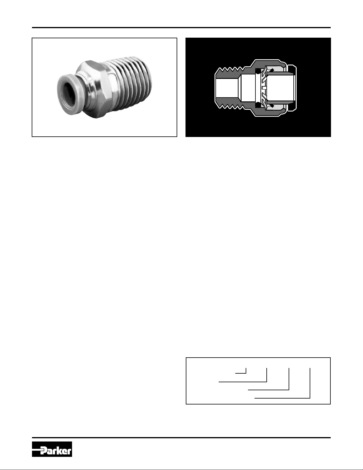
Ready-to-use compact one-piece fitting for use with most
thermoplastic and copper tubing. This fitting is specially
designed for low pressure circuits where fast assembly,
disassembly and reassembly is impor tant. No special
tools are needed for assembly; just insert the tubing until it
bottoms. Prestolok/Prestolok II is designed to be used with
no tube support. Radial claws on the stainless steel grab
ring grip the tubing securely to provide retention. Brass Male
pipe threads come standard with a white acrylic sealant
pre-applied (“W” prefix) swivels are featured on all male
pipe threaded shapes for installation in tight places and for
precise positioning. Prestolok/Prestolok II should not be
used for live swivel applications. The outside diameter of the
tubing to be used with the fitting is marked on the release
button. The removable release button can be color coded for
ease of identification. Standard release button is green.
Materials
Prestolok Bodies: CA377, CA360, CA345
Prestolok II Bodies: Glass Filled Nylon
O-Ring: Nitrile (other compounds available on request)
Release Button: Polyacetal
Grab Ring: Stainless Steel
Applications
Use with Parker Parflex series “E” polyethylene tubing,
series “N” nylon tubing, series “U” polyurethane tubing or
copper tubing. Perfectly adapted for use in a large variety
of industries, Prestolok II was designed as an economical
alternative for pneumatic applications that do not require
the higher pressure capacity of the standard prestolok
fittings, consult the factory with any questions regarding
special product applications. All applications should be
carefully tested through the range of conditions which may
be encountered prior to use. For inch O.D. tubing
Working Pressure and
Temperature Ranges
Prestolok: Zero to 200°F at up to 300 PSI depending
on tubing being used.
Prestolok II: Zero to 150°F at up to 150 PSI depending
on tubing being used.
Vacuum applications are dependent upon temperature
and type of tubing used.
Assembly Instructions
1. Cut thermoplastic tubing squarely, using Parker Tube
Cutter PTC 001. Metal tubing should be cut squarely
and free of burrs. Be certain the port or mating part is
clean and free of debris.
2. Insert tubing into fitting until it bottoms. A slight twisting
motion will ease the insertion. Pull on tubing to verify
it is properly retained in the fitting.
3. To disassemble, simply push the release button
against the body and remove tubing.
Order
By part number and name.
Nomenclature
Part numbers are constructed from symbols that identify
the style and size of the fitting. The first series of numbers
and letters identify the style and type fitting. The second
series of numbers describe the size.
Example 69 PL –4 –2
Male Connector
Prestolok
1/4" (4/16) Tube O.D.
1/8" (2/16) Pipe Thread
Sizes
Tube sizes are determined by the number of sixteenths
of an inch in the tube O.D.
2
Parker Hannifin Corporation
Pneumatic Division
Richland, Michigan
www.parker.com/pneumatic
Page 3
Pneumati
c
L
D
O.D.
Catalog 0600P-9/USA
L
2
1
D
O.D.
O.D.
L
D
D
L
B
C HEX
P
D
L
D
L
Part Numbers & Dimensions
Fittings & Tubing
Prestolok / Prestolok II Fittings
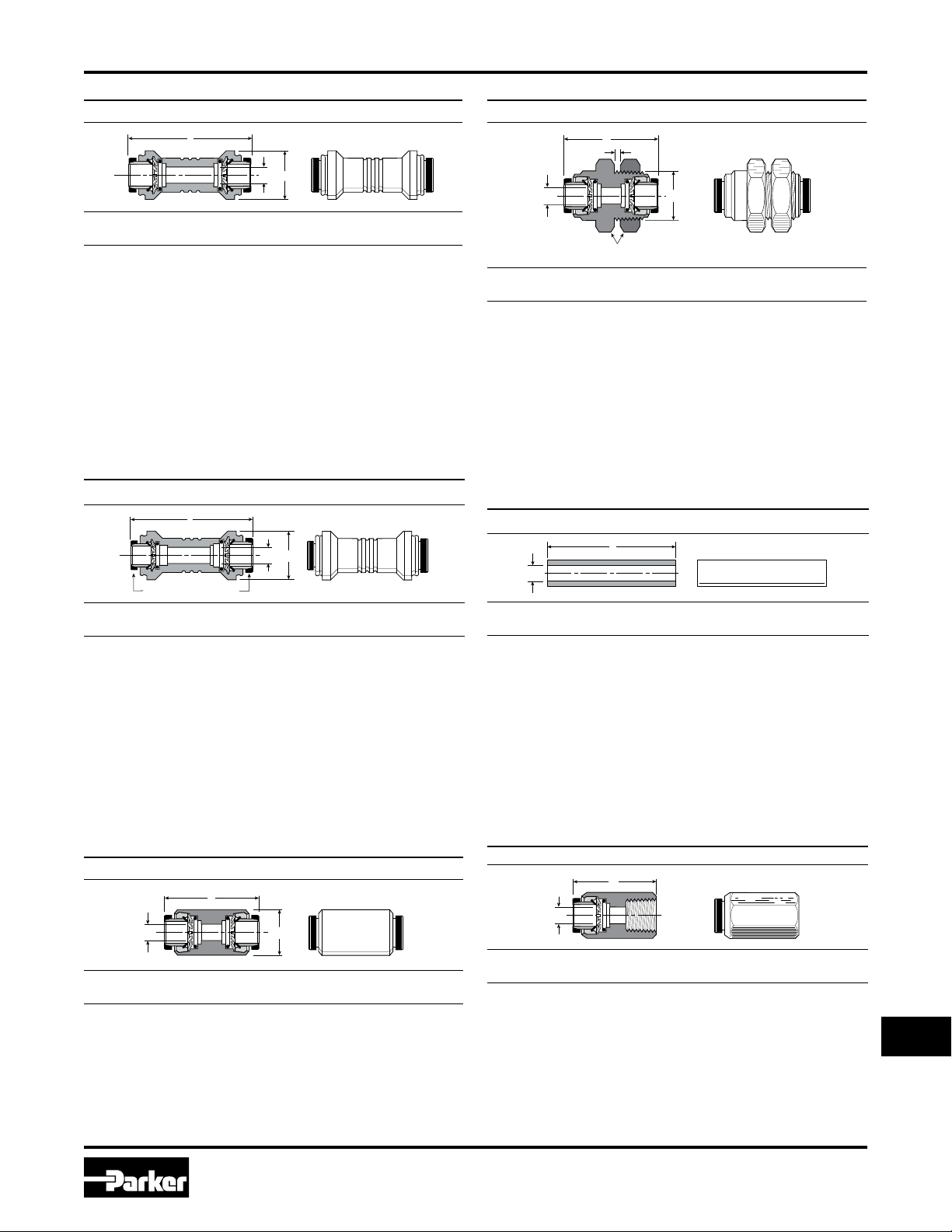
32PL Equal Union
Part
No.
32PL-2 1/8 0.51 1.32 0.09
32PL-5/32 5/32 0.51 1.32 0.12
32PL-3 3/16 0.59 1.37 0.16
32PL-4 1/4 0.59 1.37 0.19
32PL-5 5/16 0.67 1.49 0.25
32PL-6 3/8 0.83 1.76 0.31
Tube
Size O.D. L
Flow
Dia. D
32PL Unequal Union
62PLBH Bulkhead Union
Part
No.
62PLBH-2 1/8 7/16 9/16 0.39 1.44 0.094
62PLBH-5/32 5/32 7/16 9/16 0.39 1.44 0.125
62PLBH-4 1/4 9/16 11/16 0.29 1.51 0.188
62PLBH-5 5/16 5/8 3/4 0.60 1.68 0.250
62PLBH-6 3/8 3/4 7/8 0.54 1.68 0.312
62PLBH-8 1/2 7/8 1 0.66 2.07 0.375
Tube
Size B
C
HexPMax. L D
63PL Double Male Union Plastic Body
Part
No.
32PL-5/32-2 5/32 1/8 0.51 1.32 0.09
32PL-4-2 1/4 1/8 0.59 1.37 0.09
32PL-5-4 5/16 1/4 0.67 1.47 0.19
32PL-6-4 3/8 1/4 0.82 1.75 0.19
1 Tube
Size
2 Tube
Size O.D. L
62PL Union
Part
No.
62PL-2 1/8 0.406 1.44 0.094
62PL-3 3/16 0.437 1.35 0.156
62PL-5/32 5/32 0.406 1.49 0.125
62PL-4 1/4 0.500 1.51 0.188
62PL-5 5/16 0.562 1.68 0.250
62PL-6 3/8 0.625 1.68 0.312
62PL-8 1/2 0.750 1.86 0.375
Tube
Size O.D. L D
Flow
Dia. D
Part
No.
63PL-2 1/8 1.49 0.078
63PL-5/32 5/32 1.49 0.106
63PL-4 1/4 1.61 0.188
63PL-5 5/16 1.61 0.236
63PL-6 3/8 2.00 0.295
63PL-8 1/2 2.12 0.374
Tube
Size L D
66PL Female Connector
Part
No.
66PL-2-2 1/8 1/8 1.18 .094
66PL-3-2 3/16 1/8 1.16 .156
66PL-5/32-2 5/32 1/8 1.18 .125
66PL-5/32-4 5/32 1/4 1.39 .125
66PL-4-2 1/4 1/8 1.21 .188
66PL-4-4 1/4 1/4 1.42 .188
66PL-5-2 5/16 1/8 1.27 .250
66PL-5-4 5/16 1/4 1.47 .250
66PL-6-4 3/8 1/4 1.46 .312
66PL-6-6 3/8 3/8 1.51 .312
3
Tube
Size
Pipe Thread
(NPTF)
Parker Hannifin Corporation
Pneumatic Division
Richland, Michigan
www.parker.com/pneumatic
L D
Z
Page 4
Pneumati
c
Catalog 0600P-9/USA
D
L
C HEX
P
D
L
2
1
D
L
M
C HEX
D
L
M
C HEX
L
D
O.D.
D
L
L
L
Part Numbers & Dimensions
Fittings & Tubing
Prestolok / Prestolok II Fittings
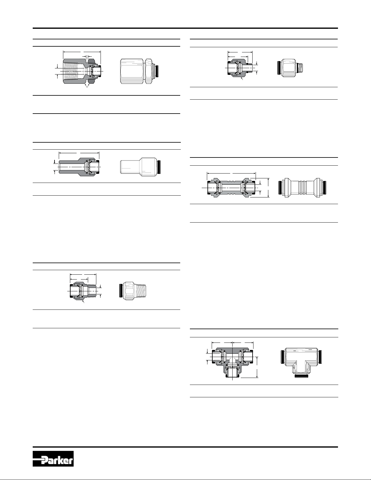
66PLBH Female Bulkhead
Part
No.
66PLBH-5/32-4
66PLBH-4-4 1/4 1/4 11/16 0.19 1.35 0.18 9/16
66PLBH-6-6 3/8 3/8 1 0.22 1.44 0.31 7/8
66PLBH-8-6 1/2 3/8 1 1/4 0.35 1.57 0.34 1
Pipe
Tube
Thread
Size
(NPTF) C HexP Max. L
5/32 1/4 11/16 0.24 1.38 0.13 1/2
Flow
Dia. DBulkhead
Hole Dia.
67PPL Tube End Reducer Plastic Body
Part
No.
67PPL-2-5/32
67PPL-2-4
67PPL-5/32-4 *
67PPL-5/32-5 *
67PPL-5/32-6 *
67PPL-4-5
67PPL-4-6
67PPL-4-8
67PPL-5-6 *
67PPL-6-8
* Parts supplied with black bodies and black release buttons
1 Tube
Size 2 Tube Size L D
1/8 5/32 1.48 0.078
1/8 1/4 1.48 0.078
5/32 1/4 1.48 0.118
5/32 5/16 1.41 0.118
5/32 3/8 1.63 0.118
1/4 5/16 1.52 0.177
1/4 3/8 1.64 0.177
1/4 1/2 1.72 0.177
5/16 3/8 1.79 0.236
3/8 1/2 1.92 0.295
W68PL Male Connector
68PL-X-10x32 Male connector
Part
No.
68PL-2-10X32
68PL-5/32-10X32
68PL-4-10X32
Tube
Thread
Size
(UNF)CHex L M D
1/8 10-32 3/8 0.93 0.68 0.094 0.094
5/32 10-32
1/4 10-32 1/2 1.00 0.71 0.094 0.094
13/32
0.95 0.69 0.094 0.094
Internal
Broach
PLHBF4-B BSPP Male Connector
Part
No.
3-1/8PLHBF4-B 3/16 1/8-28 11/16 0.96 0.156
3-1/4PLHBF4-B 3/16 1/4-19 3/4 0.97 0.156
4-1/8PLHBF4-B 1/4 1/8-28 11/16 1.13 0.188
4-1/4PLHBF4-B 1/4 1/4-19 3/4 1.13 0.188
4-3/8PLHBF4-B 1/4 3/8-19 7/8 1.13 0.188
6-1/4PLHBF4-B 3/8 1/4-19 3/4 1.26 0.256
6-3/8PLHBF4-B 3/8 3/8-19 7/8 1.26 0.312
6-1/2PLHBF4-B 3/8 1/2-14 1-1/16 1.26 0.312
8-3/8PLHBF4-B 1/2 3/8-19 7/8 1.41 0.452
8-1/2PLHBF4-B 1/2 1/2-14 1-1/16 1.37 0.452
Tube
Size
Pipe
Thread
(BSPP)CHex L D
Part
No.
W68PL-2-1 1/8 1/16 3/8 0.85 0.68 0.094
W68PL- 2-2 1/8 1/8 7/16 0.85 0.68 0.094
W68PL-2-4 1/8 1/4 9/16 1.10 0.68 0.094
W68PL-3-2 3/16 1/8 7/16 0.92 0.63 0.156
W68PL-3-4 3/16 1/4 9/16 1.10 0.64 0.156
W68PL-5/32-2 5/32 1/8 7/16 0.85 0.69 0.125
W68PL-5/32-4 5/32 1/4 9/16 1.10 0.69 0.125
W68PL-4-1 1/4 1/16 1/2 1.15 0.71 0.140
W68PL-4-2 1/4 1/8 1/2 0.97 0.71 0.188
W68PL-4-4 1/4 1/4 9/16 1.10 0.71 0.188
W68PL-4-6 1/4 3/8 3/4 1.14 0.71 0.188
W68PL-5-2 5/16 1/8 9/16 1.23 0.78 0.234
W68PL-5-4 5/16 1/4 9/16 1.11 0.78 0.250
W68PL-5-6 5/16 3/8 11/16 1.12 0.79 0.250
W68PL-6-2 3/8 1/8 11/16 1.26 0.78 0.234
W68PL-6-4 3/8 1/4 11/16 1.14 0.78 0.312
W68PL-6-6 3/8 3/8 11/16 1.09 0.79 0.312
W68PL-6-8 3/8 1/2 7/8 1.34 0.78 0.312
W68PL-8-4 1/2 1/4 13/16 1.52 0.87 0.344
W68PL-8-6 1/2 3/8 13/16 1.31 0.87 0.344
W68PL-8-8 1/2 1/2 7/8 1.43 0.87 0.375
Tube
Size
Pipe
Thread
(NPTF)CHex L M D
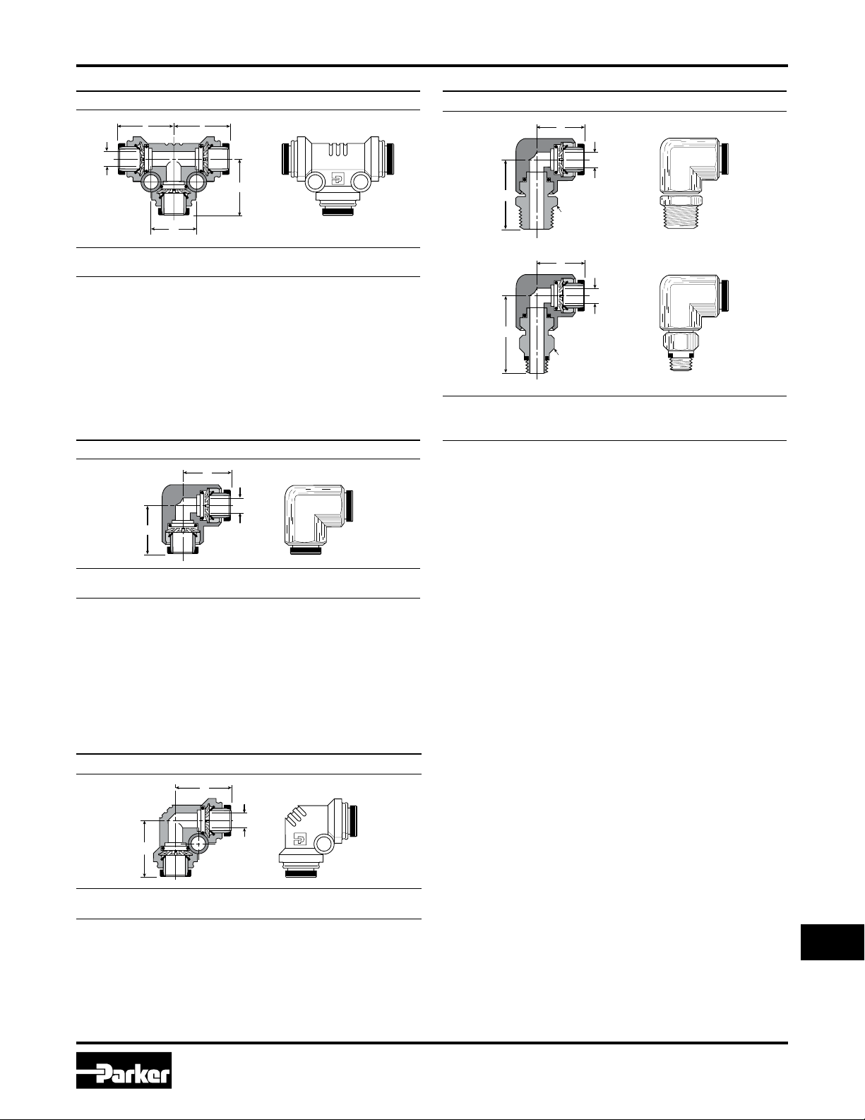
164PL Union Tee
Part
No.
164PL-2 1/8 0.78 0.094
164PL-3 3/16 0.79 0.156
164PL-5/32 5/32 0.81 0.125
164PL-4 1/4 0.94 0.188
164PL-5 5/16 0.99 0.250
164PL-6 3/8 1.04 0.312
164PL-8 1/2 1.17 0.375
4
Tube
Size L D
Parker Hannifin Corporation
Pneumatic Division
Richland, Michigan
www.parker.com/pneumatic
Page 5
Pneumati
c
Catalog 0600P-9/USA
D
L
L
D
L
G
L
L
C HEX
D
L
N
D
L
L
C HEX
D
L
N
Part Numbers & Dimensions
Fittings & Tubing
Prestolok / Prestolok II Fittings
364PL Union Tee Composite Body
Part
No.
364PL-2 1/8 0.13 0.71 0.52 0.094
364PL-5/32 5/32 0.13 0.71 0.52 0.125
364PL-3 3/16 0.17 0.76 0.64 0.156
364PL-4 1/4 0.17 0.76 0.64 0.188
364PL-5 5/16 0.17 0.84 0.71 0.250
364PL-6 3/8 0.17 1.04 0.83 0.312
364PL-8 1/2 0.17 1.30 0.99 0.344
Tube
Mounting
Size
Hole Dia. L G D
165PL Union Elbow
Part
No.
165PL-2 1/8 0.77 0.094
165PL-5/32 5/32 0.79 0.125
165PL-4 1/4 0.86 0.188
165PL-5 5/16 0.97 0.250
165PL-6 3/8 1.03 0.312
165PL-8 1/2 1.17 0.375
Tube
Size L D
365PL Union Elbow Composite Body
W169PL Male Elbow Swivel 90°
169PL-X-10/32
Part
No.
W169PL-2-2
169PL-2-10X32
W169PL-2-4
W169PL-3-2
W169PL-5/32-2
W169PL-5/32-4
169PL-5/32-10X32
W169PL-4-2
W169PL-4-4
W169PL-4-6
169PL-4-10X32
W169PL-5-2
W169PL-5-4 5/16 1/4 9/16 0.99 1.60 0.234
W169PL-6-2 3/8 1/8 9/16 1.04 1.49 0.297
W169PL-6-4 3/8 1/4 9/16 1.04 1.66 0.297
W169PL-6-6 3/8 3/8 11/16 1.04 1.70 0.297
W169PL-6-8 3/8 1/2 7/8 1.04 1.89 0.297
W169PL-8-4 1/2 1/4 11/16 1.17 1.74 0.344
W169PL-8-6 1/2 3/8 3/4 1.17 1.77 0.375
W169PL-8-8 1/2 1/2 7/8 1.16 1.97 0.375
Tube
Size
3/16 1/8 7/16 0.79 1.16 0.156
5/32 1/8 7/16 0.80 1.24 0.109
5/32 1/4 9/16 0.81 1.42 0.109
5/32 10-32 3/8 0.81 1.04 0.094
5/16 1/8 1/2 0.99 1.42 0.234
Pipe
Thread
(NPTF)CHex L N D
1/8 1/8 7/16 0.78 1.22 0.094
1/8 10-32 3/8 0.78 1.02 0.094
1/8 1/4 9/16 0.78 1.40 0.094
1/4 1/8 7/16 0.86 1.13 0.172
1/4 1/4 9/16 0.86 1.31 0.172
1/4 3/8 11/16 0.86 1.35 0.172
1/4 10-32 7/16 0.86 0.94 0.094
Part
No. Tube Size
365PL-2 1/8 0.13 0.71 0.094
365PL-3 3/16 0.17 0.76 0.156
365PL-5/32 5/32 0.13 0.71 0.125
365PL-4 1/4 0.17 0.76 0.188
365PL-5 5/16 0.17 0.84 0.250
365PL-6 3/8 0.17 1.04 0.312
365PL-8 1/2 0.17 1.03 0.344
Mounting
Hole Dia. L D
Z
5
Parker Hannifin Corporation
Pneumatic Division
Richland, Michigan
www.parker.com/pneumatic
Page 6
Pneumati
c
Catalog 0600P-9/USA
D
N
C HEX
L
C HEX
D
L
N
C HEX
D
L
N
C HEX
D
L
N
Part Numbers & Dimensions
Fittings & Tubing
Prestolok / Prestolok II Fittings
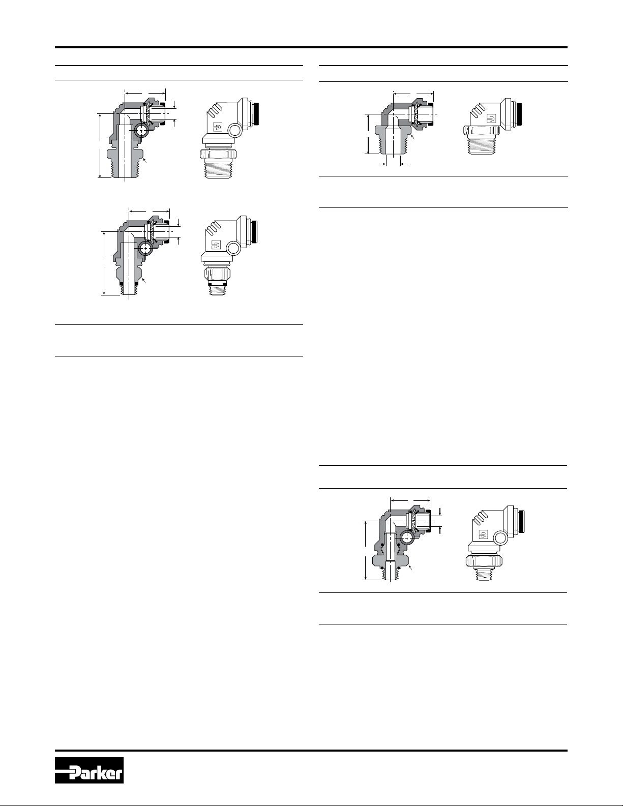
W369PL Male Elbow Swivel 90° Composite Body
369PL-X-10/32
Part
No.
W369PL-2-1 1/8 1/16 3/8 0.13 0.71 1.08 0.078
W369PL-2-2 1/8 1/8 7/16 0.13 0.71 1.14 0.078
369PL-2-10X32 1/8 10-32 3/8 0.13 0.71 0.94 0.078
W369PL-2-4 1/8 1/4 9/16 0.13 0.71 1.32 0.078
W369PL-3-2 3/16 1/8 7/16 0.17 0.76 1.20 0.147
W369PL-3-4 3/16 1/4 9/16 0.17 0.76 1.44 0.147
W369PL-5/32-2 5/32 1/8 7/16 0.13 0.74 1.14 0.094
W369PL-5/32-4 5/32 1/4 9/16 0.13 0.74 1.32 0.094
369PL-5/32-10X32
W369PL-4-1 1/4 1/16 7/16 0.17 0.76 1.20 0.094
W369PL-4-2 1/4 1/8 7/16 0.17 0.76 1.20 0.172
W369PL-4-4 1/4 1/4 9/16 0.17 0.77 1.38 0.172
W369PL-4-6 1/4 3/8 11/16 0.17 0.77 1.42 0.172
369PL-4-10X32 1/4 10-32 7/16 0.17 0.76 1.05 0.094
W369PL-5-2 5/16 1/8 1/2 0.17 0.84 1.23 0.234
W369PL-5-4 5/16 1/4 9/16 0.17 0.84 1.46 0.234
W369PL-6-2 3/8 1/8 9/16 0.17 1.04 1.48 0.234
W369PL-6-4 3/8 1/4 5/8 0.17 1.04 1.66 0.234
W369PL-6-6 3/8 3/8 11/16 0.17 1.04 1.66 0.297
W369PL-6-8 3/8 1/2 7/8 0.17 1.05 1.85 0.297
W369PL-8-4 1/2 1/4 3/4 0.17 1.03 1.80 0.314
W369PL-8-6 1/2 3/8 3/4 0.17 1.03 1.80 0.375
W369PL-8-8 1/2 1/2 7/8 0.17 1.03 1.99 0.375
Pipe
Tube
Thread
Size
(NPTF)CHex
5/32 10-32 3/8 0.13 0.74 0.94 0.094
Mounting
Hole Dia. L N D
W369PLC Compact Elbow
Part
No.
W369PLC-2-2 1/8 1/8 7/16 0.81 0.71 0.08
W369PLC-5/32-2 5/32 1/8 7/16 0.83 0.71 0.08
W369PLC-5/32-4 5/32 1/4 9/16 0.83 0.89 0.08
W369PLC-3-2 3/16 1/8 7/16 0.86 0.81 0.08
W369PLC-4-2 1/4 1/8 7/16 0.86 0.81 0.08
W369PLC-4-4 1/4 1/4 9/16 0.86 0.99 0.08
W369PLC-5-4 5/16 1/4 9/16 0.94 0.97 0.11
W369PLC-6-4 3/8 1/4 5/8 1.13 1.07 0.20
W369PLC-6-6 3/8 3/8 3/4 1.13 1.15 0.20
Tube
Pipe
Thread
Size
(NPTF)CHex L N
Flow
Dia. D
PLE2BF4-K BSPP Male Elbow Swivel
Composite Body
Part
No.
3-1/8PLE2BF4-K 3/16 1/8-28 11/16 0.17 0.76 1.17 0.147
3-1/4PLE2BF4-K 3/16 1/4-19 3/4 0.17 0.76 1.31 0.147
4-1/8PLE2BF4-K 1/4 1/8-28 11/16 0.17 0.76 1.06 0.180
4-1/4PLE2BF4-K 1/4 1/4-19 3/4 0.17 0.76 1.31 0.172
4-3/8PLE2BF4-K 1/4 3/8-19 7/8 0.17 0.76 1.31 0.182
6-1/4PLE2BF4-K 3/8 1/4-19 3/4 0.17 1.04 1.57 0.297
6-3/8PLE2BF4-K 3/8 3/8-19 7/8 0.17 1.04 1.68 0.297
6-1/2PLE2BF4-K 3/8 1/2-14 1-1/16 0.17 1.04 1.83 0.297
8-3/8PLE2BF4-K 1/2 3/8-19 7/8 0.17 1.03 1.63 0.406
8-1/2PLE2BF4-K 1/2 1/2-19 1-1/16 0.17 1.03 1.78 0.406
Tube
Size
Pipe
Thread
(BSPP)CHex
Mounting
Hole Dia. L N D
6
Parker Hannifin Corporation
Pneumatic Division
Richland, Michigan
www.parker.com/pneumatic
Page 7
Pneumati
c
Catalog 0600P-9/USA
C HEX
D
L
N
D
L
N
D
D
C HEX
N
L
L
C HEX
D
L
N
Part Numbers & Dimensions
Fittings & Tubing
Prestolok / Prestolok II Fittings
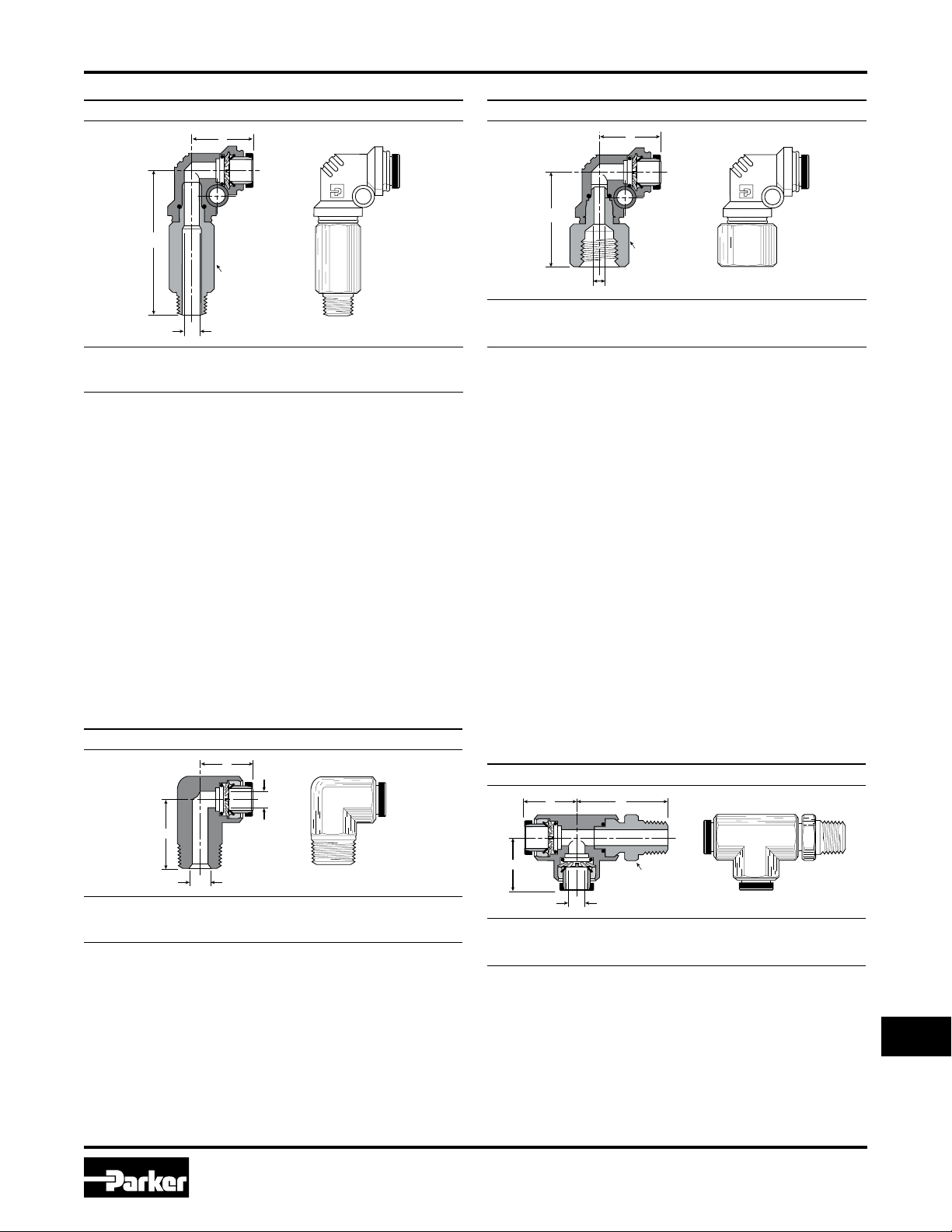
W369PLX Male Elbow Swivel 90° Composite Body
Pipe
Tube
Part No.
W369PLX-2-2 1/8 1/8 7/16 0.13 0.73 1.74 0.080
W369PLX-2-4 1/8 1/4 9/16 0.13 0.73 1.74 0.080
W369PLX-3-2 3/16 1/8 7/16 0.17 0.76 1.88 0.150
W369PLX-3-4 3/16 1/4 9/16 0.17 0.76 1.88 0.150
W369PLX-3-6 3/16 3/8 11/16 0.17 0.76 1.88 0.150
W369PLX-4-2 1/4 1/8 7/16 0.17 0.76 1.88 0.170
W369PLX-4-4 1/4 1/4 9/16 0.17 0.76 1.88 0.170
W369PLX-4-6 1/4 3/8 11/16 0.17 0.76 1.88 0.170
369PLX-5/32-0 5/32 10-32 3/8 0.13 0.73 1.54 0.090
W369PLX-5/32-2
W369PLX-5/32-4
W369PLX-5-2 5/16 1/8 9/16 0.17 0.84 1.99 0.223
W369PLX-5-4 5/16 1/4 9/16 0.17 0.84 1.99 0.230
W369PLX-5-6 5/16 3/8 11/16 0.17 0.84 1.99 0.230
W369PLX-6-4 3/8 1/4 5/8 0.17 1.04 2.56 0.223
W369PLX-6-6 3/8 3/8 11/16 0.17 1.04 2.56 0.300
W369PLX-6-8 3/8 1/2 7/8 0.17 1.04 2.56 0.300
W369PLX-8-4 1/2 1/4 3/4 0.17 1.03 2.80 0.310
W369PLX-8-6 1/2 3/8 3/4 0.17 1.03 2.80 0.340
W369PLX-8-8 1/2 1/2 7/8 0.17 1.03 2.80 0.340
Thread
Size
(NPTF)CHex
5/32 1/8 7/16 0.13 0.73 1.54 0.090
5/32 1/4 9/16 0.13 0.73 1.54 0.090
Mounting
Hole Dia. L N D
370PL Female Elbow Swivel Composite Body
Part
No.
370PL-2-2 1/8 1/8 9/16 0.13 0.71 1.01 0.078
370PL-5/32-2 5/32 1/8 9/16 0.13 0.73 1.01 0.090
370PL-5/32-4 5/32 1/4 3/4 0.13 0.73 1.23 0.090
370PL-4-10x32 1/4 10x32 7/16 0.17 0.76 1.02 0.159
370PL-4-2 1/4 1/8 9/16 0.17 0.76 1.07 0.170
370PL-4-4 1/4 1/4 3/4 0.17 0.76 1.29 0.170
370PL-5-4 5/16 1/4 3/4 0.17 0.84 1.37 0.230
370PL-6-4 3/8 1/4 3/4 0.17 1.04 1.57 0.297
370PL-8-6 1/2 3/8 7/8 0.17 1.03 1.57 0.340
Tube
Size
Pipe
Thread
(NPTF)CHex
Mounting
Hole Dia. L N D
W169PLNS Male Elbow 90°
W171PL Male Run Tee Swivel
Part
No. Tube Size
W169PLNS-2-2 1/8 1/8 0.78 0.68 0.094
W169PLNS-5/32-2
W169PLNS-5/32-4
W169PLNS-4-2 1/4 1/8 0.86 0.68 0.188
W169PLNS-4-4 1/4 1/4 0.96 0.89 0.188
W169PLNS-5-2 5/16 1/8 0.98 0.78 0.234
W169PLNS-5-4 5/16 1/4 1.02 0.97 0.250
W169PLNS-6-4 3/8 1/4 1.04 0.97 0.312
W169PLNS-6-6 3/8 3/8 1.11 1.09 0.312
W169PLNS-6-8 3/8 1/2 1.20 1.26 0.312
W169PLNS-8-6 1/2 3/8 1.31 1.15 0.375
W169PLNS-8-8 1/2 1/2 1.31 1.31 0.375
5/32 1/8 0.81 0.68 0.125
5/32 1/4 0.81 0.89 0.125
Pipe
Thread
(NPTF) L N D
Part
No.
W171PL-2-2 1/8 1/8 7/16 0.78 1.22 0.078
W171PL-5/32-2 5/32 1/8 7/16 0.80 1.24 0.109
W171PL-4-2 1/4 1/8 7/16 0.96 1.29 0.188
W171PL-4-4 1/4 1/4 9/16 0.96 1.47 0.188
W171PL-5-2 5/16 1/8 1/2 0.99 1.42 0.234
W171PL-5-4 5/16 1/4 9/16 0.99 1.60 0.234
W171PL-6-4 3/8 1/4 9/16 1.04 1.66 0.297
W171PL-6-6 3/8 3/8 11/16 1.04 1.70 0.297
W171PL-8-6 1/2 3/8 3/4 1.19 1.79 0.375
W171PL-8-8 1/2 1/2 7/8 1.19 1.98 0.375
Tube
Size
7
Pipe
Thread
(NPTF)CHex L N D
Parker Hannifin Corporation
Pneumatic Division
Richland, Michigan
www.parker.com/pneumatic
Z
Page 8

Pneumati
c
Catalog 0600P-9/USA
D
L
L
C HEX
N
D
L
G
L
C HEX
N
C HEX
N
D
L
G
L
D
L
G
L
C HEX
N
Part Numbers & Dimensions
Fittings & Tubing
Prestolok / Prestolok II Fittings
W371PL Male Run Tee Swivel Composite Body
Part
No.
Tube
Size
Thread
(NPTF)CHex
W371PL-2-1 1/8 1/16 3/8 0.13 0.71 1.08 0.52 0.078
W371PL-2-2 1/8 1/8 7/16 0.13 0.71 1.14 0.52 0.078
W371PL-2-4 1/8 1/4 9/16 0.13 0.71 1.32 0.52 0.080
371PL-2-10x32 1/8 10-32 3/8 0.13 0.71 0.94 0.52 0.078
W371PL-3-2 3/16 1/8 7/16 0.17 0.76 1.20 0.64 0.150
W371PL-3-4 3/16 1/4 9/16 0.17 0.76 1.40 0.64 0.147
W371PL-5/32-2 5/32 1/8 7/16 0.13 0.71 1.14 0.52 0.094
W371PL-5/32-4 5/32 1/4 9/16 0.13 0.71 1.14 0.52 0.094
371PL-5/32- 10x32 5/32 10-32 3/8 0.13 0.71 0.94 0.52 0.090
W371PL-4-1 1/4 1/16 7/16 0.17 0.76 1.20 0.64 0.094
Pipe
Mtg.
Hole
Dia. L N G D
W172PL Male Branch Tee Swivel
Part
Tube
No.
W172PL-2-2 1/8 1/8 7/16 0.78 1.22 0.078
W172PL-3-2 3/16 1/8 7/16 0.78 1.17 0.156
W172PL-5/32-2 5/32 1/8 7/16 0.80 1.24 0.109
W172PL-4-2 1/4 1/8 7/16 0.96 1.26 0.188
W172PL-4-4 1/4 1/4 9/16 0.96 1.44 0.188
W172PL-5-2 5/16 1/8 1/2 0.99 1.42 0.234
W172PL-5-4 5/16 1/4 9/16 0.99 1.60 0.234
W172PL-6-4 3/8 1/4 9/16 1.04 1.66 0.297
W172PL-6-6 3/8 3/8 11/16 1.04 1.70 0.297
W172PL-8-6 1/2 3/8 3/4 1.19 1.79 0.375
W172PL-8-8 1/2 1/2 7/8 1.19 1.98 0.375
Pipe
Thread
Size
(NPTF)CHex L N D
W371PL-4-2 1/4 1/8 7/16 0.17 0.76 1.20 0.64 0.170
W371PL-4-4 1/4 1/4 9/16 0.17 0.76 1.38 0.64 0.170
W372PL Male Branch Tee Swivel Composite Body
371PL-4-10x32 1/4 10-32 7/16 0.13 0.76 1.05 0.64 0.094
W371PL-4-6 1/4 3/8 11/16 0.17 0.76 1.42 0.64 0.170
W371PL-5-2 5/16 1/8 9/16 0.17 0.84 1.28 0.71 0.220
W371PL-5-4 5/16 1/4 9/16 0.17 0.84 1.46 0.71 0.234
W371PL-6-2 3/8 1/8 9/16 0.13 1.04 1.48 0.83 0.230
W371PL-6-4 3/8 1/4 5/8 0.17 1.04 1.66 0.83 0.297
W371PL-6-6 3/8 3/8 11/16 0.17 1.04 1.70 0.83 0.297
W371PL-6-8 3/8 1/2 7/8 0.13 1.04 1.85 0.83 0.300
W371PL-8-4 1/2 1/4 3/4 0.17 1.30 2.07 1.00 0.310
W371PL-8-6 1/2 3/8 3/4 0.17 1.30 1.68 1.00 0.344
W371PL-8-8 1/2 1/2 7/8 0.17 1.30 2.26 1.00 0.344
PLR2BF4-K BSPP Male Run Tee Swivel
Composite Body
Part
No.
W372PL-2-1 1/8 1/16 3/8 0.13 0.71 1.08 0.52 0.078
W372PL-2-2 1/8 1/8 7/16 0.13 0.71 1.14 0.52 0.078
W372PL-2-4 1/8 1/4 9/16 0.13 0.70 1.32 0.52 0.080
Tube
Size
Pipe
Thread
(NPTF)CHex
Mtg.
Hole
Dia. L N G D
372PL-2-10X32 1/8 10-32 3/8 0.13 0.70 0.94 0.52 0.080
W372PL-3-2 3/16 1/8 7/16 0.17 0.76 1.20 0.64 0.147
W372PL-3-4 3/16 1/4 9/16 0.17 0.76 1.40 0.64 0.147
W372PL-5/32-2 5/32 1/8 7/16 0.13 0.71 1.14 0.52 0.094
W372PL-5/32-4 5/32 1/4 9/16 0.13 0.68 1.32 0.52 0.090
372PL-5/32-10x32 5/32 10-32 3/8 0.13 0.70 0.94 0.52 0.090
W372PL-4-1 1/4 1/16 7/16 0.17 0.76 1.20 0.64 0.094
W372PL-4-2 1/4 1/8 7/16 0.17 0.76 1.20 0.64 0.170
W372PL-4-4 1/4 1/4 9/16 0.17 0.76 1.38 0.64 0.170
372PL-4-10x32 1/4 10-32 7/16 0.17 0.76 1.05 0.64 0.090
W372PL-4-6 1/4 3/8 11/16 0.17 0.76 1.42 0.64 0.170
W372PL-5-2 5/16 1/8 9/16 0.17 0.84 1.28 0.71 0.234
W372PL-5-4 5/16 1/4 9/16 0.17 0.84 1.23 0.71 0.234
W372PL-6-2 3/8 1/8 9/16 0.17 1.03 1.48 0.83 0.230
W372PL-6-4 3/8 1/4 5/8 0.17 1.04 1.66 0.83 0.297
W372PL-6-6 3/8 3/8 11/16 0.17 1.04 1.66 0.83 0.297
W372PL-6-8 3/8 1/2 7/8 0.17 1.03 1.85 0.83 0.300
W372PL-8-4 1/2 1/4 3/4 0.17 1.30 2.07 0.99 0.310
W372PL-8-6 1/2 3/8 3/4 0.17 1.30 2.07 0.99 0.344
W372PL-8-8 1/2 1/2 7/8 0.17 1.30 2.26 0.99 0.344
8
Parker Hannifin Corporation
Pneumatic Division
Richland, Michigan
www.parker.com/pneumatic
Part
No.
Tube
Size
Pipe
Thread
(BSPP)CHex
Mtg.
Hole
Dia. L N G D
3-1/4PLR2BF4-K 3/16 1/4-19 3/4 0.17 0.76 1.31 0.64 0.150
4-1/8PLR2BF4-K 1/4 1/8-28 11/16 0.17 0.76 1.06 0.64 0.170
4-1/4PLR2BF4-K 1/4 1/4-19 3/4 0.17 0.76 1.31 0.64 0.170
6-1/4PLR2BF4-K 3/8 1/4-19 3/4 0.17 1.04 1.52 0.83 0.300
6-3/8PLR2BF4-K 3/8 3/8-19 7/8 0.17 1.04 1.68 0.83 0.300
8-3/8PLR2BF4-K 1/2 3/8-19 7/8 0.17 1.30 1.90 0.99 0.340
8-1/2PLR2BF4-K 1/2 1/2-19 1-1/16 0.17 1.30 2.05 0.99 0.340
Page 9
Pneumati
c
Catalog 0600P-9/USA
C HEX
N
D
L
G
L
L
C HEX
D
N
L
G
L
D
G
L
N
N1
D
G
L
NN
1
Part Numbers & Dimensions
Fittings & Tubing
Prestolok / Prestolok II Fittings
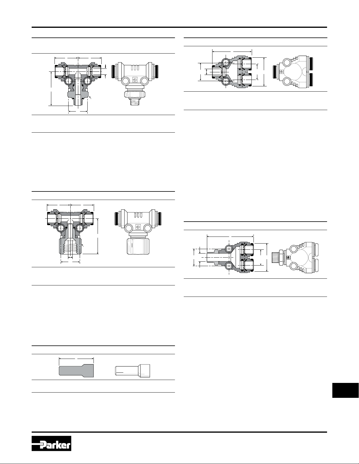
PLS2BF4-K BSPP Male Branch Tee Swivel
Composite Body
Part
No.
3-1/8PLS2BF4-K 3/16 1/8-28 11/16 0.17 0.76 1.05 0.64 0.150
3-1/4PLS2BF4-K 3/16 1/4-19 3/4 0.17 0.76 1.31 0.64 0.150
4-1/8PLS2BF4-K 1/4 1/8-28 11/16 0.17 0.76 1.06 0.64 0.180
4-1/4PLS2BF4-K 1/4 1/4-19 3/4 0.17 0.76 1.31 0.64 0.170
6-1/4PLS2BF4-K 3/8 1/4-19 3/4 0.17 1.04 1.57 0.83 0.300
6-3/8PLS2BF4-K 3/8 3/8-19 7/8 0.17 1.04 1.68 0.83 0.300
6-1/2PLS2BF4-K 3/8 1/2-14 1-1/16 0.17 1.04 1.83 0.83 0.300
8-3/8PLS2BF4-K 1/2 3/8-19 7/8 0.17 1.30 1.90 0.99 0.410
Tube
Size
Pipe
Thread
(BSPP)CHex
Mtg.
Hole
Dia. L N G D
377PL Female Branch Tee Swivel Composite Body
362PL Union Y Connector Composite Body
Part
No.
362PL-2 1/8 0.13 1.38 0.92 0.41 0.57 0.130
362PL-5/32 5/32 0.13 1.36 0.92 0.41 0.57 0.160
362PL-3 3/16 0.17 1.49 1.13 0.54 0.67 0.200
362PL-4 1/4 0.17 1.49 1.13 0.53 0.67 0.260
362PL-5 5/16 0.17 1.49 1.21 0.54 0.72 0.320
362PL-6 3/8 0.17 1.88 1.54 0.71 0.76 0.380
Tube
Mtg.
Hole
Size
Dia. L N N1 G D
W368PL Union Y Male Connector Composite Body
Part
No.
377PL-2-2 1/8 1/8 9/16 0.17 0.70 1.01 0.52 0.080
377PL-5/32-2 5/32 1/8 9/16 0.13 0.70 1.01 0.52 0.090
377PL-5/32-4 5/32 1/4 3/4 0.13 0.70 1.23 0.52 0.090
377PL-4-2 1/4 1/8 9/16 0.17 0.76 1.07 0.64 0.170
377PL-4-4 1/4 1/4 3/4 0.17 0.76 1.29 0.64 0.170
377PL-5-4 5/16 1/4 3/4 0.17 0.84 1.37 0.72 0.230
377PL-6-4 3/8 1/4 3/4 0.17 1.04 1.57 0.83 0.300
377PL-8-6 1/2 3/8 7/8 0.17 1.30 1.84 0.99 0.410
Tube
Size
Pipe
Thread
(NPTF)CHex
639PL Plug
Part
No.
639PL-2 1/8 1.30
639PL-5/32 5/32 1.34
639PL-4 1/4 1.34
639PL-5 5/16 1.28
639PL-6 3/8 1.50
639PL-8 1/2 1.69
Tube
Size L
Mtg.
Hole
Dia. L N G D
Part
No.
W368PL-2-2 1/8 1/8 0.57 0.13 1.81 0.91 0.41 0.080
W368PL-2-4 1/8 1/4 0.57 0.13 1.98 0.91 0.41 0.080
368PL-5/32-10x32 5/32 10-32 0.57 0.13 1.60 0.92 0.41 0.090
W368PL-5/32-2 5/32 1/8 0.57 0.13 1.80 0.92 0.41 0.090
W368PL-5/32-4 5/32 1/4 0.57 0.13 1.98 0.92 0.41 0.090
368PL-3-10x32 3/16 10-32 0.67 0.17 1.77 1.13 0.54 0.094
W368PL-3-2 3/16 1/8 0.67 0.17 1.92 1.13 0.54 0.150
W368PL-3-4 3/16 1/4 0.67 0.17 2.16 1.13 0.54 0.150
W368PL-3-6 3/16 3/8 0.67 0.17 2.16 1.13 0.54 0.147
368PL-4-10x32 1/4 10-32 0.67 0.17 1.78 1.13 0.53 0.090
W368PL-4-2 1/4 1/8 0.67 0.17 1.93 1.13 0.53 0.172
W368PL-4-4 1/4 1/4 0.67 0.17 2.11 1.13 0.53 0.170
W368PL-4-6 1/4 3/8 0.67 0.17 2.15 1.13 0.53 0.170
W368PL-5-2 5/16 1/8 0.72 0.17 1.87 1.20 0.54 0.230
W368PL-5-4 5/16 1/4 0.72 0.17 2.10 1.20 0.54 0.230
W368PL-5-6 5/16 3/8 0.72 0.17 2.04 1.20 0.54 0.234
W368PL-6-4 3/8 1/4 0.76 0.17 2.50 1.53 0.71 0.300
W368PL-6-6 3/8 3/8 0.76 0.17 2.50 1.53 0.71 0.300
W368PL-6-8 3/8 1/2 0.76 0.17 2.69 1.53 0.71 0.300
Tube
Size
Pipe
Size G
9
Mtg.
Hole
Dia. L N N1 D
Parker Hannifin Corporation
Pneumatic Division
Richland, Michigan
www.parker.com/pneumatic
Z
Page 10

Pneumati
c
Catalog 0600P-9/USA
Basic Features
Fittings & Tubing P Fittings
Advantages
A compact brass compression fitting designed to speed
any installation. Body, nut and sleeve are furnished
preassembled, ready for installation. An exclusive acetal
copolymer sleeve holds plastic tubing where it belongs,
even when the system pressure exceeds the tubing burst
point. P fitting sleeves have superior resilience to resist
creeping and stress caused from compression. The black
acetal copolymer sleeve also resists ultra-violet ray attack
and has excellent dimensional stability. P fitting nuts will
rotate around the sleeve as it tightens to prevent twisting
and weakening of the plastic tubing. P fittings can be
assembled and disassembled repeatedly.
Materials
Elbows and Tees: Brass Forgings: CA 377
Connectors, Unions, Nuts: CA 360, CA 345
Plastic Sleeves: Acetal Copolymer (Celcon®).
Applications
Use with Parker or other high-quality thermoplastic tubing
for pneumatic instrumentation circuits, lubricant and
coolant lines, and applications with other gases and liquids.
For use with soft metal tubing and nylon thermoplastic
tubing, use brass sleeve and nut assembly 61PB.
Working Pressure and
Temperature Ranges
Up to 150 PSI from 0° to + 150°F with thermoplastic tubing.
Up to 300 PSI from 0° to +175°F with soft metal tubing.
Assembly Instructions
Polyethylene, polypropylene and vinyl tubing:
1.
Cut tubing squarely - maximum of 15° angle allowable.
2. Check that port or mating part is clean and free of
debris.
3.
Insert tube end until it bottoms in the fitting and tighten
knurl / hex nut finger tight - plus one wrench turn.
Copper, aluminum and nylon tubing:
Brass sleeves are recommended. Insert tube until it
bottoms in the P fitting and tighten one wrench turn past
finger-tight.
Maximum allowable metal tube wall
thickness for use with P fittings:
1/8", 3/16", O.D. — no limitation, 1/4" O.D. — 0.035
5/16", 3/8", 1/2" O.D. — 0.049.
Nomenclature
Part numbers are constructed from symbols that identify
the style and size of the fitting. The first series of numbers
and letters identifies the style and type fitting. The second
series of numbers describes the size.
Example:
66 P -4 -2
Female Connector
(Tube to female pipe)
P Fitting
1/4" (4/16) Tube O.D.
1/8" (2/16) Pipe Thread
Sizes
Tube sizes are determined by the number of sixteenths
of an inch in the tube O.D.
10
Parker Hannifin Corporation
Pneumatic Division
Richland, Michigan
www.parker.com/pneumatic
Page 11

Pneumati
c
Catalog 0600P-9/USA
L
A
L
A
D
L
D
C HEX
L
D
C HEX
L
D
C HEX
L
M
C HEX
D
L
M
1 2
C HEX
D
Part Numbers & Dimensions
Fittings & Tubing
P Fittings
59P Plastic Cap
Part
No.
59P-4 1/4 0.247 0.50
59P-5
59P-6 3/8 0.372 0.56
59P-8
Tube
Size A L
5/16 0.307 0.53
1/2 0.497 0.63
60P Acetal Plastic Sleeve
Part
No.
60P-4
60P-5
60P-6 3/8 0.465 0.381 0.367
60P-8
Tube
Size A D L
1/4 0.334 0.261 0.338
5/16 0.405 0.321 0.340
1/2 0.628 0.514 0.399
61PN Nut
Part
No.
61PN-2 1/8 5/16-24 3/8 0.34
61PN-3
61PN-4 1/4 3/8-24 7/16 0.38
61PN-5 5/16 7/16-24 1/2 0.34
61PN-6
61PN-8 1/2 11/16-20 3/4 0.44
Tube
Size
3/16 3/8-24 7/16 0.37
3/8 1/2-24 9/16 0.38
Straight
Thread C Hex L
62P Union
61P Nut and Sleeve Assembly
Part
No.
61P-2* 1/8 5/16-24 3/8 0.130 0.34
61P-3*
61P-4
61P-5 5/16 7/16-24 1/2 0.321 0.34
61P-6
61P-8 1/2 11/16-20 3/4 0.514 0.44
*Brass Sleeve
Tube
Size
3/16 3/8-24 7/16 0.192 0.37
1/4 3/8-24 7/16 0.261 0.38
3/8 1/2-24 9/16 0.380 0.38
Straight
ThreadCHex D L
Part
No.
62P-2*
62P-3* 3/16 3/8-24 3/8 1.16 0.73 0.125
62P-4
62P-5 5/16 7/16-24 7/16 1.16 0.96 0.144
62P-6 3/8 1/2-24 1/2 1.23 0.99 0.204
62P-8
*Brass Sleeve, No Tube Support
Tube
Straight
Size
ThreadCHex L M
1/8 5/16-24 5/16 1.08 0.64 0.094
1/4 3/8-24 3/8 1.17 0.96 0.125
1/2 11/16-20 11/16 1.47 1.24 0.323
Flow
Dia. D
61PB* Nut and Sleeve Assembly
62P Union Reducer
Part
No.
61PB-4
61PB-5 5/16 7/16-24 1/2 0.318 0.34
61PB-6
61PB-8 1/2 11/16-20 3/4 0.507 0.44
*Brass Sleeve
Tube
Size
1/4 3/8-24 7/16 0.255 0.38
3/8 1/2-24 9/16 0.382 0.38
Straight
ThreadCHex D L
1
2
Part
No.
62P-6-4 1/4 3/8 3/8-24 1/2-24 1/2 1.22 0.99 0.125
Tube
Size
Tube
Size
1
Straight
Thread
11
2
Straight
ThreadC Hex L M
Parker Hannifin Corporation
Pneumatic Division
Richland, Michigan
www.parker.com/pneumatic
Z
Flow
Dia. D
Page 12

Pneumati
c
Catalog 0600P-9/USA
L
M
P
C HEX
D
L
M
P
C HEX
D
L
M
D
1
2
C HEX
L
M
D
C HEX
1 2
P
L
M
C HEX
D
L
M
D
C HEX
L
M
D
C HEX
Part Numbers & Dimensions
Fittings & Tubing
P Fittings
62PBH Bulkhead Union
Part
No.
62PBH-4
62PBH-5 5/16 7/16-24 5/8 0.38 1.71 1.52 7/16 0.144
62PBH-6 3/8 1/2-24 11/16 0.47 1.89 1.65 1/2 0.204
62PBH-8
Tube
Straight
Size
ThreadCHexPMax. L M
Bulkhead
Hole Dia.
Flow
Dia. D
1/4 3/8-24 9/16 0.38 1.75 1.53 3/8 0.125
1/2 11/16-20 7/8 0.63 2.28 2.05 11/16 0.323
62PCA Union (Tube to CA Fitting)
Part
No.
62PCA-4
Tube
Straight
Size
Thread
1/4 3/8-24 7/16-24 7/16 1.25 0.89 0.125
62PCA-5 5/16 7/16-24 1/2-24 1/2 1.30 0.92 0.144
1
62PCA-6
3/8 1/2-24 9/16-24 9/16 1.37 0.98 0.204
2
Straight
ThreadCHex L M
Flow
Dia. D
66P Female Connector
Part
No.
66P-2-2*
66P-3-2* 3/16 1/8 3/8-24 9/16 1.00 0.78 0.125
66P-3-4* 3/16 1/4 3/8-24 11/16 1.18 0.96 0.125
66P-4-2
66P-4-4 1/4 1/4 3/8-24 5/8 1.18 1.07 0.125
66P-5-2
66P-6-4 3/8 1/4 1/2-24 5/8 1.18 1.07 0.204
66P-8-6
*Brass Sleeve, No Tube Support
Tube
Size
Pipe
Thread
Straight
Thread CHex L M
Flow
Dia. D
1/8 1/8 5/16-24 9/16 0.97 0.75 0.094
1/4 1/8 3/8-24 1/2 0.97 0.86 0.125
5/16 1/8 7/16-24 1/2 0.97 0.86 0.144
1/2 3/8 11/16-20 13/16 1.31 1.20 0.323
68P Male Connector
62PCABH Bulkhead Union (Tube to CA Fitting)
Part
No.
62PCABH-4 1/4 3/8-24 7/16-24 9/16 0.38 1.81 1.45 3/8 0.125
62PCABH-6
Tube
Size
3/8 1/2-24 9/16-24 11/16 0.47 2.03 1.64 1/2 0.204
62PTBH Bulkhead Union (Straight Through)
Part
No.
62PTBH-4
62PTBH-5 5/16 7/16-24 5/8 0.31 1.19 0.93 7/16 0.323
62PTBH-6
Tube
Size
1/4 3/8-24 9/16 0.31 1.19 0.93 3/8 0.260
3/8 1/2-24 11/16 0.34 1.26 0.99 1/2 0.387
1
Straight
Thread
2
Straight
Thread CHex PMax. L M
Straight
ThreadCHexP Max. L M
Bulkhead
Hole
Dia.
Bulkhead
Hole Dia.
Flow
Dia.
D
Flow
Dia. D
68P-2-10 x 32
Part
No.
68P-2-1*
Tube
Pipe
Size
Thread
Straight
ThreadCHex L M
1/8 1/16 5/16-24 11/32 1.00 0.78 0.094
68P-2-2* 1/8 1/8 5/16-24 7/16 0.99 0.77 0.094
68P-3-1
3/16 1/16 3/8-24 7/16 1.09 0.84 0.094
68P-3-2* 3/16 1/8 3/8-24 7/16 1.06 0.84 0.125
68P-3-4*
3/16 1/4 3/8-24 9/16 1.25 1.03 0.125
68P-4-1 1/4 1/16 3/8-24 3/8 1.06 0.95 0.125
68P-4-2
1/4 1/8 3/8-24 7/16 1.06 0.95 0.125
68P-4-4 1/4 1/4 3/8-24 9/16 1.25 1.14 0.125
68P-4-6
1/4 3/8 3/8-24 11/16 1.28 1.17 0.125
68P-5-2 5/16 1/8 7/16-24 7/16 1.05 0.95 0.144
68P-5-4
5/16 1/4 7/16-24 9/16 1.24 1.14 0.144
68P-6-2 3/8 1/8 1/2-24 1/2 1.10 0.98 0.204
68P-6-4
3/8 1/4 1/2-24 9/16 1.29 1.17 0.204
68P-6-6 3/8 3/8 1/2-24 11/16 1.29 1.17 0.204
68P-8-4
1/2 1/4 11/16-20 11/16 1.46 1.29 0.320
68P-8-6 1/2 3/8 11/16-20 11/16 1.37 1.29 0.323
68P-2-10 x 32* 1/8 10-32 5/16-24 3/8 0.86 0.64 0.094
68P-4-10 x 32 1/4 10-32 3/8-24 3/8 0.86 0.75 0.094
*Brass Sleeve, No Tube Support
12
Parker Hannifin Corporation
Pneumatic Division
Richland, Michigan
www.parker.com/pneumatic
Flow
Dia. D
Page 13

Pneumati
c
Catalog 0600P-9/USA
L
H
C HEX
D
L
P H
C HEX
D
H
C SQ
D
F
H
C SQ
D
F
H
C SQ
D
F
M
L
P H
F
C HEX
Part Numbers & Dimensions
Fittings & Tubing
P Fittings
391P Pipe Coupler Body (Chrome Plated)
Part
No.
391P-4-2
391P-4-4 1/4 1/4 9/16 0.73 1.29
391P-6-4
D
Insert
Dia.
1/4 1/8 1/2 0.91 1.29
3/8 1/4 5/8 0.85 1.41
Pipe
ThreadCHex H L
392P Bulkhead Coupler Body (Chrome Plated)
393PD Shut-off Type Insert (Chrome Plated)
393PD-4-4
393PD-6-6
Part
No.
393PD-4-4
393PD-6-6 3/8 3/8 1/2-24 1/2 1.45 0.187
Tube
Size
1/4 1/4 3/8-24 7/16 1.61 0.110
D
Insert
Dia.
Straight
ThreadCSquare H
Flow
Dia. F
Part
No.
392P-4-4
392P-6-6 3/8 3/8 11/16-24 13/16 0.93 0.37 2.01 11/16
D
Tube
Insert
Size
1/4 1/4 1/2-24 5/8 0.84 0.39 2.13 1/2
Straight
Dia.
ThreadCHexP Max. H L
Bulkhead
Hole Dia.
394P Single End Shut-off Bulkhead Quick Coupler
‡
(Chrome Plated)
393P Through Type Insert (Chrome Plated)
Bulk-
Part
No.
393P-4-4 1/4 1/4 3/8-24 7/16 1.12 0.125
393P-6-6
Tube
Size
3/8 3/8 1/2-24 1/2 1.34 0.203
D
Insert
Straight
Dia.
ThreadCSquare H
Flow
Dia. F
Part
No.
394P-4-4 1/4 1/2 - 24 5/8 0.84 0.39 3.28 2.13 1/2 0.125
394P-6-6
‡ Same as 392P-*-* and 393P-*-* Assembled.
13
Tube
Straight
Size
ThreadCHexPMax. H L M
3/8 11/16-24 13/16 0.93 0.37 3.41 2.01 11/16 0.203
Parker Hannifin Corporation
Pneumatic Division
Richland, Michigan
www.parker.com/pneumatic
head
Hole
Dia.
Flow
Dia. F
Z
Page 14

Pneumati
c
L
M
C HEX
F
Catalog 0600P-9/USA
M
L
P H
C HEX
F
F
M
L
P H
C HEX
L
M
C HEX
F
L
M
C HEX
F
L
L
L
M
M
M
D
Part Numbers & Dimensions
Fittings & Tubing
P Fittings
394PD Double End Shut-off Bulkhead
Quick Coupler‡ (Chrome Plated)
394PD-4-4
398PD Double End Shut-off Pipe Connector Quick Coupler
‡
(Chrome Plated)
394PD-4-X
394PD-6-4
394PD-6-6
Bulk-
head
Part
No.
394PD-4-4
Tube
Straight
Size
ThreadCHexP Max. H L M
1/4 1/2-24 5/8 0.84 0.39 3.77 2.13 1/2 0.125
Hole
Dia.
Flow
Dia.
394PD-6-6 3/8 11/16-24 13/16 0.93 0.47 3.48 2.01 11/16 0.204
‡ Same as 393PD-*-* and 392P-*-* Assembled.
Part
No.
398PD-4-2
398PD-4-4
398PD-6-4 3/8 1/4 1/2-24 5/8 3.10 1.43 0.204
F
‡ Same as 391P-*-* and 393PD-*-* Assembled.
Tube
Pipe
Size
Thread
Straight
ThreadCHex L M
1/4 1/8 3/8-24 1/2 2.93 1.31 0.125
1/4 1/4 3/8-24 9/16 2.93 1.32 0.125
Flow
Dia. F
164P-264P Union Tee
398P Single End Shut-off Pipe Connector Quick Coupler
Part No.
398P-4-2 1/4 1/8 3/8-24 1/2 2.45 1.32 0.125
398P-4-4
398P-6-4 3/8 1/4 1/2-24 5/8 2.80 1.46 0.203
‡ Same as 391P-*-* and 393P-*-* Assembled.
‡
(Chrome Plated)
Tube
Size
Pipe
Thread
Straight
Thread C Hex L M
Flow
Dia. F
1/4 1/4 3/8-24 9/16 2.45 1.32 0.125
Tube
Part No.
Straight
Size
Thread L M
164P-2* 1/8 5/16-24 0.83 0.61 0.094
264P-3*
3/16 3/8-24 0.83 0.61 0.125
164P-4 1/4 3/8-24 0.84 0.73 0.125
164P-5
5/16 7/16-24 0.83 0.73 0.144
164P-6 3/8 1/2-24 0.98 0.86 0.203
164P-8
*Brass Sleeve, No Tube Support
14
1/2 11/16-20 1.12 1.04 0.323
Parker Hannifin Corporation
Pneumatic Division
Richland, Michigan
www.parker.com/pneumatic
Flow
Dia. D
Page 15

Pneumati
c
Catalog 0600P-9/USA
L
L
1
L
M
1
3
1 2
D
M
M
D
N
L
M
D
N
L
M
D
N
L
M
D
N
L
M
L
L
N
M
M
D
Part Numbers & Dimensions
Fittings & Tubing
P Fittings
164P Union Tee Combination Size
1
2
Part
No.
164P-6-4A
Tube
Tube
Size
Size
3/8 3/8 1/4 0.98 0.90 0.86 0.79 0.125
3
Tube
Size L L
1
169P-269P Male Elbow
M M
1
Flow
Dia. D
169PS Male Elbow Swivel
Part
No.
169PS-4-2
169PS-4-4
Tube
Pipe
Size
Straight
Thread
ThreadCHexEHex L M N
1/4 1/8 3/8-24 3/8 7/16 0.81 0.59 0.86 0.121
1/4 1/4 3/8-24 9/16 9/16 0.91 0.69 1.22 0.125
169PS-6-2 3/8 1/8 1/2-24 7/16 7/16 0.88 0.63 0.90 0.203
169PS-6-4 3/8 1/4 1/2-24 9/16 9/16 0.94 0.69 1.22 0.203
169PS-6-6
3/8 3/8 1/2-24 9/16 11/16 0.86 0.60 1.19 0.203
169PS-8-6 1/2 3/8 11/16-20 1/2 11/16 1.03 0.78 1.22 0.323
Flow
Dia.
D
170P Female Elbow
Part
No.
Tube
Size
169P-2-1 1/8 1/16 5/16-24 0.88 0.63 0.69 0.094
269P-2-2*
1/8 1/8 5/16-24 0.83 0.61 0.67 0.094
169P-3-1 3/16 1/16 3/8-24 0.88 0.63 0.69 0.094
169P-3-2*
3/16 1/8 3/8-24 0.83 0.61 0.69 0.125
169P-3-4* 3/16 1/4 3/8-24 0.85 0.63 0.94 0.125
169P-4-1
169P-4-2
1/4 1/16 3/8-24 0.92 0.58 0.67 0.130
1/4 1/8 3/8-24 0.84 0.73 0.75 0.121
169P-4-4 1/4 1/4 3/8-24 0.90 0.79 0.92 0.125
169P-4-6 1/4 3/8 3/8-24 0.93 0.84 1.08 0.125
169P-5-2
5/16 1/8 7/16-24 0.87 0.73 0.68 0.144
169P-6-2 3/8 1/8 1/2-24 0.93 0.81 0.73 0.203
169P-6-4
3/8 1/4 1/2-24 0.98 0.86 1.05 0.203
169P-6-6 3/8 3/8 1/2-24 0.98 0.86 1.08 0.203
169P-8-6
*Brass Sleeve, No Tube Support
1/2 3/8 11/16-20 1.12 1.04 1.13 0.323
169LP Long Male Elbow
Part
No.
Tube
Size
169LP-4-4 1/4 1/4 3/8-24 0.90 0.79 1.38 0.125
Pipe
Thread
Thread
Straight
Thread L M N
Pipe
Straight
Thread L M N
Flow
Dia. D
Flow
Dia. D
Part
No.
170P-2-2*
Tube
Pipe
Size
Thread
Straight
Thread L M N
1/8 1/8 5/16-24 0.91 0.69 0.56 0.094
170P-3-2* 3/16 1/8 3/8-24 0.91 0.69 0.56 0.125
170P-4-2
1/4 1/8 3/8-24 0.90 0.79 0.56 0.125
170P-4-4 1/4 1/4 3/8-24 1.00 0.89 0.69 0.125
170P-6-4
3/8 1/4 1/2-24 1.01 0.89 0.69 0.204
170P-8-6 1/2 3/8 11/16-20 1.19 1.11 1.13 0.323
*Brass Sleeve, No Tube Support
171P Male Run Tee
Part
No.
171P-2-2*
171P-3-2* 3/16 1/8 3/8-24 0.82 0.60 0.67 0.125
171P-4-2
171P-4-4 1/4 1/4 3/8-24 0.92 0.81 0.92 0.125
171P-5-2
171P-6-4 3/8 1/4 1/2-24 0.98 0.86 1.03 0.203
171P-8-6
*Brass Sleeve, No Tube Support
15
Tube
Pipe
Size
Thread
Straight
Thread L M N
1/8 1/8 5/16-24 0.82 0.60 0.67 0.094
1/4 1/8 3/8-24 0.84 0.73 0.72 0.125
5/16 1/8 7/16-24 0.83 0.73 0.72 0.144
1/2 3/8 11/16-20 1.12 1.04 1.13 0.323
Parker Hannifin Corporation
Pneumatic Division
Richland, Michigan
www.parker.com/pneumatic
Flow
Dia. D
Flow
Dia. D
Z
Page 16

Pneumati
c
Catalog 0600P-9/USA
L
N
L
M M
D
L
N
L
M M
D
H
L
M N
H
H
L
M
Part Numbers & Dimensions
Fittings & Tubing
P Fittings
172P Male Branch Tee
Part
No.
172P-2-2* 1/8 1/8 5/16-24 0.82 0.60 0.67 0.094
172P-3-2* 3/16 1/8 3/8-24 0.82 0.60 0.67 0.125
172P-4-2
172P-4-4
172P-5-2 5/16 1/8 7/16-24 0.83 0.73 0.72 0.144
172P-6-2
172P-6-4 3/8 1/4 1/2-24 0.98 0.86 1.03 0.204
172P-8-6
*Brass Sleeve, No Tube Support
Tube
Pipe
Size
Thread
1/4 1/8 3/8-24 0.84 0.73 0.72 0.125
1/4 1/4 3/8-24 0.92 0.81 0.92 0.125
3/8 1/8 1/2-24 0.88 0.86 0.74 0.204
1/2 3/8 11/16-20 1.12 1.04 1.13 0.323
Straight
Thread L M N
Flow
Dia. D
177P Female Branch Tee
NV312P Angle Needle Valve
Part
No.
NV312P-4-2 1/4 1/8 1.06 1.70 1.50 0.63 0.68
NV312P-4-4
NV312P-6-4 3/8 1/4 1.06 2.00 1.75 0.74 0.86
Tube
Pipe
Size
Thread H L OpenL Closed M N
1/4 1/4 1.06 2.07 1.82 0.71 0.86
Part
No.
177P-4-2 1/4 1/8 3/8-24 0.92 0.81 0.88 0.125
177P-4-4
177P-4-6 1/4 3/8 3/8-24 1.03 0.92 1.13 0.125
Tube
Pipe
Size
Thread
1/4 1/4 3/8-24 0.92 0.81 1.03 0.125
Straight
Thread L M N
Flow
Dia. D
NV311P Needle Valve
Part
No.
NV311P-4-2 1/4 1/8 1.06 1.36 1.16 0.64 0.63
NV311P-4-4 1/4 1/4 1.06 1.38 1.18 0.64 0.72
NV311P-6-4
Tube
Pipe
Size
Thread H L OpenL Closed M N
3/8 1/4 1.06 1.38 1.18 0.64 0.72
16
Parker Hannifin Corporation
Pneumatic Division
Richland, Michigan
www.parker.com/pneumatic
Page 17

Pneumati
c
Catalog 0600P-9/USA
Notes
Fittings & Tubing
P Fittings
Z
17
Parker Hannifin Corporation
Pneumatic Division
Richland, Michigan
www.parker.com/pneumatic
Page 18

Pneumati
c
Catalog 0600P-9/USA
Basic Features
Fittings & Tubing DB Fittings
Advantages
Compact one piece, push-on barbed fitting for a quick,
economical way to connect polyethylene tubing. Extruded
from CA 360 or CA 345 brass rod.
Applications
Because of the many available variations in qualities of
polyethylene tubing DB fittings are recommended for
use with Parker polyethylene tubing (or an equal grade).
Parker tubing is highly resistant to environmental stress
cracking which is necessary for long life when coupled
with expansion fittings.
Working Pressure and
Temperature Ranges
In tube sizes 1/4 to 3/8 working pressures up to 150
psi are practical at temperatures ranging from -65° to
+90°F. On 1/2" tube size, working pressures to 100 psi
at temperatures ranging from -65° to +75°F.
Nomenclature
Part numbers are constructed from symbols that identify
the style and size of the fitting. The first series of numbers
and letters identifies the style and type fitting. The second
series of numbers describes the size.
Example:
231 -8 -6
Run Tee (tube
to male pipe)
1/2" (8/16) Tube O.D.
3/8" (6/16) Pipe Thread
Sizes
Tube sizes are determined by the number of sixteenths
of an inch in the tube O.D.
Assembly Instructions
Simply push tube over the two barbs — be sure tubing
is cut square.
18
Parker Hannifin Corporation
Pneumatic Division
Richland, Michigan
www.parker.com/pneumatic
Page 19

Pneumati
c
Catalog 0600P-9/USA
L
M
C
L
M
D
L
M
D
L
M
D
P
C HEX
L
D
C HEX
L
D
C HEX
L
D
2
1
C HEX
L
C HEX
D
Part Numbers & Dimensions
Fittings & Tubing
DB Fittings
20 Plug
Part
No.
20-4 1/4 0.170 0.290 0.56 0.41
20-6 3/8 0.250 0.390 0.68 0.44
20-8 1/2 0.377 0.577 0.81 0.56
Tube
O.D.
Tube
I.D.
C
Dia. L M
22 Union
Part
No.
22-5/32
22-4 1/4x1/4 0.170x0.170 0.84 0.41 0.120
22-6
22-8 1/2x1/2 0.375x0.375 1.19 0.56 0.312
Tube
O.D.
5/32x5/32 0.096x0.096 0.59 0.28 0.062
3/8x3/8 0.250x0.250 0.94 0.44 0.187
Tube
I.D. L M
Flow
Dia. D
26 Female Connector
Part
No.
26-5/32-2
26-4-2 1/4 0.170 1/8 1/2 0.91 0.120
26-6-2
26-6-4 3/8 0.250 1/4 11/16 1.06 0.187
Tube
Tube
O.D.
5/32 0.096 1/8 1/2 0.79 0.062
3/8 0.250 1/8 1/2 0.93 0.187
Pipe
I.D.
ThreadCHex L
Flow
Dia. D
27 Male Connector
Part
No.
27-1*
27-2* 1/4 0.125 10-32 UNF 1/4 0.74 0.093
*For vinyl tubing only.
Tube
Tube
O.D.
1/8 0.062 10-32 UNF 1/4 0.61 0.052
I.D.
Pipe
ThreadCHex L
Flow
Dia. D
22 Union Reducer
Part
No.
22-4-5/32
22-4-6 1/4x3/8 0.170x0.250 0.88 0.44 0.120
22-4-8
22-6-8 3/8x1/2 0.250x0.375 1.06 0.56 0.187
Tube
O.D.
1/4x5/32 0.170x0.096 0.72 0.41 0.062
1/4x1/2 0.170x0.375 1.06 0.56 0.120
Tube
I.D. L M
22BH Bulkhead Union
Part
No.
22BH-4-4 1/4 0.170 5/16-24 7/16 0.219 1.38 0.78 0.120
22BH-6-6
Tube
O.D.
3/8 0.250 3/8-24 7/16 0.375 1.63 1.00 0.187
Tube
I.D.
Straight
ThreadCHexP Max. L M
Flow
Dia. D
Flow
Dia. D
28 Barb to Pipe Adapter
Part
No.
28-4-5/32-2 5/32 0.096 1/4 0.170 1/8 7/16 1.07 0.062
Tube
O.D. 1
Tube
I.D. 1
Tube
O.D. 2
Tube
Pipe
I.D. 2
Thread CHex F
28 Male Connector
Part
No.
28-5/32-2 5/32 0.096 1/8 7/16 0.84 0.062
28-4-1
28-4-2 1/4 0.170 1/8 7/16 0.97 0.120
28-4-4
28-6-2 3/8 0.250 1/8 7/16 1.00 0.187
28-6-4
28-8-4 1/2 0.375 1/4 9/16 1.25 0.312
28-8-6
28-8-8 1/2 0.375 1/2 7/8 1.44 0.312
19
Tube
O.D.
Tube
I.D.
1/4 0.170 1/16 11/32 0.93 0.120
1/4 0.170 1/4 9/16 1.09 0.120
3/8 0.250 1/4 9/16 1.13 0.187
1/2 0.375 3/8 11/16 1.28 0.312
Pipe
ThreadCHex L
Parker Hannifin Corporation
Pneumatic Division
Richland, Michigan
www.parker.com/pneumatic
Flow
Dia. D
Flow
Dia. D
Z
Page 20

Pneumati
c
N
D
L
L
Catalog 0600P-9/USA
D
L
M
M
D
M
L
D
L
M
N
D
1
D
M
L
N
D
N
M
D
M
M
12
Part Numbers & Dimensions
Fittings & Tubing
DB Fittings
220 Adapter Tee
Part
No.
220-4-2 1/4 0.170 1/8 1.5 1.0 0.120
Tube
O.D.
Tube
Pipe
I.D.
Thread L M
Flow
Dia. D
224 Union Tee
225 Union Elbow
Part
No.
225-5/32
225-4-4 1/4 0.170 0.63 0.63 0.120
225-6-6 3/8 0.250 0.69 0.69 0.187
225-8-8
Tube
O.D.
5/32 0.096 0.50 0.50 0.062
1/2 0.375 0.81 0.81 0.312
Tube
I.D. L M
Flow Dia.
D
228 Gauge Tee
Part
No.
228-4-2
Tube
Tube
O.D.
1/4 0.170 1/8 1.91 0.66 0.44 0.120
Pipe
I.D.
Thread L M N
Flow
Dia. D
229 Male Elbow
Part
No.
224-5/32 5/32 0.096 1.000 0.50 0.062
224-4 1/4 0.170 1.250 0.63 0.120
224-6 3/8 0.250 1.375 0.69 0.187
224-8 1/2 0.375 1.625 0.81 0.312
224 Union Tee (Combination Sizes)
Tube
O.D.
Tube
I.D. L M
Flow
Dia. D
Part
No.
229-5/32-2
229-4-1
229-4-2 1/4 0.170 1/8 0.69 0.63 0.120
229-4-4
229-6-2 3/8 0.250 1/8 0.69 0.69 0.187
229-6-4
229-8-6 1/2 0.375 3/8 0.94 0.81 0.312
Tube
O.D.
5/32 0.096 1/8 0.56 0.63 0.062
Tube
1/4 0.170 1/16 0.62 0.60 0.120
1/4 0.170 1/4 0.72 0.72 0.120
3/8 0.250 1/4 0.75 0.75 0.187
Pipe
I.D.
Thread M N
Flow
Dia. D
229 Barb Adapter Elbow 90°
Flow
Part
No.
224-4-4-5/32 1/4x5/32 0.170x0.096 1.25 0.63 0.50 0.120 0.062
224-6-6-5/32 3/8x5/32 0.250x0.096 1.38 0.69 0.50 0.187 0.062
224-6-6-4
224-8-8-4 1/2x1/4 0.375x0.170 1.62 0.81 0.65 0.312 0.120
224-8-8-6
Tube
O.D.
3/8x1/4 0.250x0.170 1.38 0.69 0.62 0.187 0.120
1/2x3/8 0.375x0.250 1.62 0.81 0.69 0.312 0.187
Tube
I.D. L M N
Dia.
D
Flow
Dia.
D1
Part
No.
229-4-5/32-2 5/32 0.096 1/4 0.170 1/8 0.78 0.062
20
Tube
O.D. 1
Tube
I.D. 1
Tube
Tube
O.D. 2
I.D. 2
Parker Hannifin Corporation
Pneumatic Division
Richland, Michigan
www.parker.com/pneumatic
Pipe
Thread M
Flow
Dia. D
Page 21

Pneumati
c
Catalog 0600P-9/USA
D
L
M
N
D
L
M
N
D
L
M
N
L
N
M
M
L
D
L
D
L
M
1
2
D
L
M
N
Part Numbers & Dimensions
Fittings & Tubing
DB Fittings
230 Female Elbow
Part
No.
230-4-2
230-6-4 3/8 0.250 1/4 1.12 0.78 0.63 0.187
Tube
Tube
O.D.
1/4 0.170 1/8 0.91 0.66 0.44 0.120
Pipe
I.D.
Thread L M N
Flow
Dia. D
231 Male Run Tee
233 Tee
Part
No.
233-4-4-4 1/4 0.170 1/4 0.73 0.53 0.74 0.120
233-6-6-4
Tube
Tube
O.D.
1/4 0.170 3/8 0.87 0.59 0.80 0.120
Comp.
I.D.
Tube L M N
Flow
Dia. D
237 Female Branch Tee
Part
No.
231-4-2
231-6-2 3/8 0.250 1/8 1.38 0.69 0.69 0.187
231-6-4
Tube
Tube
O.D.
1/4 0.170 1/8 1.28 0.66 0.69 0.120
3/8 0.250 1/4 1.44 0.75 0.75 0.187
Pipe
I.D.
Thread L M N
Flow
Dia. D
Part
No.
237-4-2
Tube
Tube
O.D.
1/4 0.170 1/8 1.34 0.67 0.49 0.120
Pipe
I.D.
Thread L M N
Flow
Dia. D
238 Solder Connector
Part
No.
238-4-4
Tube
O.D. 1
1/4 0.170 0.91 0.254 0.120
Tube
I.D. 2 L M
Flow Dia.
D
232 Male Branch Tee
20GT DB Tool*
Part
No.
232-4-1
232-4-2 1/4 0.170 1/8 1.38 0.69 0.66 0.120
232-6-2
232-6-4 3/8 0.250 1/4 1.50 0.75 0.75 0.187
Tube
Tube
O.D.
1/4 0.170 1/16 1.33 0.66 0.65 0.120
3/8 0.250 1/8 1.38 0.69 0.69 0.187
Pipe
I.D.
Thread L M N
Flow
Dia. D
Part
No.
20GT-4 1/4 1.00 0.245
*For ease in assembling polyethylene tubing onto DB Fittings.
21
Tube
O.D. L Thru Dia.
Parker Hannifin Corporation
Pneumatic Division
Richland, Michigan
www.parker.com/pneumatic
Z
Page 22

Pneumati
c
Catalog 0600P-9/USA
Features & Part Numbers
Fittings & Tubing
Polyethylene Tubing
Advantages
Chemical resistant, flexible, low cost,
eight colors, five tube sizes and choice
of reel lengths.
Construction
Flexible polyethylene thermoplastic tubing
is extruded from high molecular weight
resin for increased dimensional stability,
uniformity and long-term strength. Its
resistan ce to envi ronmental str ess
cracking greatly exceeds that of ordinary
polyethylene tubing as measured by
ASTM D-1693, (10% IGEPAL).
Applications &
Approvals
Polyethylene tubing is available in
black as well as seven coding colors
as recommended by the Instrument
Society of America. Black (EB) tubing
contains an ultra-violet inhibitor which
is re c o m mended for use in sunlit
areas. Ingredients of natural and color
tubing (except black) listed below meet
FDA requirements for food contact
applications. All tubing conforms to
AST M D-12 4 8, Type I , Clas s A,
Category 4, Grade E5.
Temperature Range
Suggested operating temperature range
is -80°F to 150°F (-62°C to 66°C).
Fitting Recommendation
• Brass fittings
E Instrument Grade Tubing
Working
Reel
Part
Number Color O.D. I.D. Wall
E-43-0100 Natural 1/4 0.170 0.040 100 120 625 1 1.1
E-43-0500 Natural 1/4 0.170 0.040 500 120 625 1 1.1
E-43-1000
EB-43-0100 Black 1/4 0.170 0.040 100 120 625 1 1.1
EB-43-0500
EB-43-1000 Black 1/4 0.170 0.040 1000 120 625 1 1.1
E-43-R-0100
E-43-R-0500 Red 1/4 0.170 0.040 500 120 625 1 1.1
E-43-B-0100
E-43-B-0500
E-43-O-0500 Orange 1/4 0.170 0.040 500 120 625 1 1.1
E-43-Y-0500 Yellow 1/4 0.170 0.040 500 120 625 1 1.1
E-43-P-0500
E-43-G-0500 Green 1/4 0.170 0.040 500 120 625 1 1.1
E-53-0500
EB-53-0500 Black 5/16 0.187 0.062 500 145 800 1-1/8 2.1
E-64-0100
E-64-0500 Natural 3/8 0.250 0.062 500 125 675 1-1/4 2.5
EB-64-0100
EB-64-0500 Black 3/8 0.250 0.062 500 125 675 1-1/4 2.5
E-64-R-0500
E-64-B-0500 Blue 3/8 0.250 0.062 500 125 675 1-1/4 2.5
E-64-O-0500
E-64-Y-0500 Yellow 3/8 0.250 0.062 500 125 675 1-1/4 2.5
E-64-P-0500
E-64-G-0500 Green 3/8 0.250 0.062 500 125 675 1-1/4 2.5
E-86-0100
EB-86-0100 Black 1/2 0.375 0.062 100 90 425 2-1/2 3.6
E-108-0100
EB-108-0100 Black 5/8 0.500 0.062 Coil 70 325 4 4.6
Natural 1/4 0.170 0.040 1000 120 625 1 1.1
Black 1/4 0.170 0.040 500 120 625 1 1.1
Red 1/4 0.170 0.040 100 120 625 1 1.1
Blue 1/4 0.170 0.040 100 120 625 1 1.1
Blue 1/4 0.170 0.040 500 120 625 1 1.1
Purple 1/4 0.170 0.040 500 120 625 1 1.1
Natural 5/16 0.187 0.062 500 145 800 1-1/8 2.1
Natural 3/8 0.250 0.062 100 125 675 1-1/4 2.5
Black 3/8 0.250 0.062 100 125 675 1-1/4 2.5
Red 3/8 0.250 0.062 500 125 675 1-1/4 2.5
Orange 3/8 0.250 0.062 500 125 675 1-1/4 2.5
Purple 3/8 0.250 0.062 500 125 675 1-1/4 2.5
Natural 1/2 0.375 0.062 100 90 425 2-1/2 3.6
Natural 5/8 0.500 0.062 100 70 325 4 4.6
Length
Feet
Pressure
psi at
73°F
Min.
Burst
psi at
73°F
Bend
Radius
Inches
Min.
Weight
Per 100
Feet
Nomenclature
Part numbers are constructed from
symbols that identify the style and size
of the fitting. Letters identify style and
material. Numbers identify size in 1/16’s
of an inch.
Example:
E - 6 4 - Y - 0500
Polyethylene
3/8" (6/16) Tube O.D.
1/4" (4/16) Tube I.D.
Color, Yellow
Reel Footage
22
Parker Hannifin Corporation
Pneumatic Division
Richland, Michigan
www.parker.com/pneumatic
Page 23

Pneumati
c
Catalog 0600P-9/USA
Features & Part Numbers
Construction &
Approvals
Fl a me r es i st a nt p ol y ethy len e is
manu factured from a distinctively
formulated compound which meets
the UL94 V-2 flame classification. It
also meets the flame spread, fuel
co n tr ibut ion an d sm o ke d ens ity
requirements of the ASTM E84-81a
tunnel test.
Applications
Parker series FRPE tubing is the
preferred product for pneumatic control
applications in the heating- ventilatingair conditioning-energy conservation
industry. It is also suitable for use
in petrochemical plants, petroleum
refineries, pulp and paper mills, mines,
steel mills and other industries where
protection against intermittent flame and
hot sparks is necessary.
Fittings & Tubing
Polyethylene Tubing
Temperature Range
Sug ges ted o pe r ati n g t e mpe rat u re r ang e is - 8 5° F to 1 50° F
(-65°C to +66°C).
Nomenclature
Order by tubing part number and name.
Example:
FR PE 4 — 0500
Flame Resistant
Polyethylene
1/4" (4/16) Tube O. D.
Reel Footage
FRPE Flame Resistant Tubing
Part
Number Color O.D. I.D. Wall
FRPE2.5-0500
FRPE4-0250
FRPE4-0500
FRPE4-1000
FRPE6-0250
FRPE6-0500
FRPE8-0250
Black 5/32 0.096 0.030 500 225 900 1/2 0.56
Black 1/4 0.170 0.040 250 160 650 3/4 1.24
Black 1/4 0.170 0.040 500 160 650 3/4 1.24
Black 1/4 0.170 0.040 1000 160 650 3/4 1.24
Black 3/8 0.250 0.062 250 195 780 1-1/2 2.90
Black 3/8 0.250 0.062 500 195 780 1-1/2 2.90
Black 1/2 0.375 0.062 250 135 540 1-3/4 4.05
Reel
Length
Feet
Working
Pressure
psi at
73°F
Min.
Burst
psi at
73°F
Min.
Bend
Radius
Inches
Weight
Per 100
Feet
Z
23
Parker Hannifin Corporation
Pneumatic Division
Richland, Michigan
www.parker.com/pneumatic
Page 24

Pneumati
c
Catalog 0600P-9/USA
Features & Part Numbers
Advantages
Flexible nylon tubing is carefully made from
high-grade, abrasion-resistant, heat-and
light-stabilized nylon. Resistance to stresscracking greatly exceeds that of ordinary
nylon tubing. Extremely low level water
absorption.
Chemical-resistant nylon tubing has the
additional benefits of better flexibility, lighter
weight and resistance to flexural fatigue.
Colors
Available in natural (NN) and black (NB).
Black tubing is recommended for use outdoors and in sunlit areas.
Temperature Range
Operating temperatures, depending upon
conditions, are -65°F to 200°F (-54°C to
93°C) continuous.
Fitting Recommendations
• Brass fittings
Fittings & Tubing
Nylon Tubing – N
Nomenclature
Order by tubing part number and name.
Example:
N N — 2 — 016
Nylon
Color, Natural
1/8" (2/16) Tube O.D.
Wall Thickness in thousandths of an inch
N Flexible Tubing
*Min.
Nylon
Part No. Color
NN-2-016
NB-2-016
NN-2-031
NB-2-031
NN-2.5-025
NB-2.5-025
NN-3-025
NB-3-025
NN-3-046
NB-3-046
NN-4-035
NB-4-035
NN-4-040
NB-4-040 Black 1/4 0.170 0.040 1250 7/8 250
NN-4-062
NB-4-062
NN-5-040
NB-5-040
NN-6-050
NB-6-050
NN-6-093
NB-6-093
NN-8-062
NB-8-062
NN-8-124
NB-8-124
*Suggested working pressure is 1/4 of burst pressure.
Natural 1/8 0.093 0.016 1000 1/4 250
Black 1/8 0.093 0.016 1000 1/4 250
Natural 1/8 0.064 0.031 2000 1/4 250
Black 1/8 0.064 0.031 2000 1/4 250
Natural 5/32 0.106 0.025 1200 1/2 250
Black 5/32 0.106 0.025 1200 1/2 250
Natural 3/16 0.138 0.025 1000 5/8 250
Black 3/16 0.138 0.025 1000 5/8 250
Natural 3/16 0.096 0.046 2000 7/16 250
Black 3/16 0.096 0.046 2000 7/16 250
Natural 1/4 0.180 0.035 1000 7/8 250
Black 1/4 0.180 0.035 1000 7/8 250
Natural 1/4 0.170 0.040 1250 7/8 250
Natural 1/4 0.127 0.062 2000 1/2 250
Black 1/4 0.127 0.062 2000 1/2 250
Natural 5/16 0.233 0.040 1250 1-1/8 250
Black 5/16 0.233 0.049 1250 1-1/8 250
Natural 3/8 0.275 0.050 1250 1-1/8 250
Black 3/8 0.275 0.050 1250 1-1/8 250
Natural 3/8 0.190 0.093 2000 3/4 250
Black 3/8 0.190 0.093 2000 3/4 250
Natural 1/2 0.375 0.062 1000 1-1/4 250
Black 1/2 0.375 0.062 1000 1-1/4 250
Natural 1/2 0.253 0.124 2000 1 250
Black 1/2 0.253 0.124 2000 1 250
Nom.
Tube
O.D.
Nom.
Tube
I.D.
Average
Wall
Thick.
Burst
Pressure
at 73°F
psi
Min.
Bend
Radius
Inches
Length
Std.
Reel
Feet
24
Parker Hannifin Corporation
Pneumatic Division
Richland, Michigan
www.parker.com/pneumatic
Page 25

Pneumati
c
Catalog 0600P-9/USA
Features & Part Numbers
Advantages
Series NR semi-rigid nylon tubing offers
better chemical resistance than series N,
good resistance to high ambient temperature and low moisture absortion. NR has a
high tensile strength which will give excellent coupling retention in high pressure,
temperature and vibration environments.
Construction
Parker series NR tubing is manufactured
from a semi-rigid nylon II material. The
tubing does not contain plasticizers.
Applications & Approvals
NR tubing is specified for machine tool
lubricating systems, marine control systems,
process lines for chemicals and oils and
other applications requiring a high quality
nylon tube.
Temperature Range
The recommended operating temperature
range for service at rated pressures with
compatible fluids is -60°F to 200°F (-51°C
to 93°C).
Fittings & Tubing
Nylon Tubing – NR
Fitting Recommendations
• Brass fittings
Nomenclature
Order by tubing part number and name.
Example:
N B R 2 016
Nylon
Color, Black
Rigid
1/8" (2/16) Tube O.D.
Wall Thickness in thousandths of an inch
NR Semi-rigid High Strength Tubing
*Min.
Nylon
Part No. Color
NNR-2-017 Natural 1/8 0.091 0.017 1700 1/2 500
NBR-2-017
NNR-2-026 Natural 1/8 0.073 0.026 2500 3/8 500
NBR-2-026
NNR-3-024 Natural 3/16 0.140 0.024 1700 3/4 500
NBR-3-024 Black 3/16 0.140 0.024 1700 3/4 500
NNR-3-039
NBR-3-039
NNR-4-035 Natural 1/4 0.180 0.035 1700 1 250
NBR-4-035
NNR-4-050 Natural 1/4 0.150 0.050 2500 7/8 250
NBR-4-050 Black 1/4 0.150 0.050 2500 7/8 250
NNR-5-040
NBR-5-040
NNR-6-048 Natural 3/8 0.279 0.048 1700 1-3/4 250
NBR-6-048 Black 3/8 0.279 0.048 1700 1-3/4 250
NNR-6-075
NBR-6-075 Black 3/8 0.225 0.075 2500 1-1/2 250
NNR-8-062
NBR-8-062 Black 1/2 0.376 0.062 1500 2-3/8 250
NNR-8-075
NBR-8-075 Black 1/2 0.350 0.075 2200 2-1/2 250
*Suggested working pressure is 1/4 of burst pressure.
Black 1/8 0.091 0.017 1700 1/2 500
Black 1/8 0.073 0.026 2500 3/8 500
Natural 3/16 0.110 0.039 2500 5/8 500
Black 3/16 0.110 0.039 2500 5/8 500
Black 1/4 0.180 0.035 1700 1 250
Natural 5/16 0.233 0.040 1700 1-1/2 250
Black 5/16 0.233 0.040 1700 1-1/2 250
Natural 3/8 0.225 0.075 2500 1-1/2 250
Natural 1/2 0.376 0.062 1500 2-3/8 250
Natural 1/2 0.350 0.075 2200 2-1/2 250
Nom.
Tube
O.D.
Nom.
Tube
I.D.
Average
Wall
Thick.
Burst
Pressure
at 73 °F
psi
Min
Bend
Radius
Inches
Length
Std.
Reel
Feet
PTC Plastic Tube Cutter
Part No. PTC
An easy to handle razor/edged tube cutter, closes
automatically, assuring clean and square cuts.
May be used with polyethylene, polypropylene, nylon and
other plastic tubing.
How To Use
Insert plastic tube to desired length, allow tube cutter to
close, then apply pressure until tube snaps off.
25
Parker Hannifin Corporation
Pneumatic Division
Richland, Michigan
www.parker.com/pneumatic
Z
Page 26

Pneumati
c
Minimum
Burst
Pressure
(psig)
3.0
2.8
2.6
2.4
2.2
2.0
1.8
1.6
1.4
1.2
1.0
0.8
0.6
0.4
0.2
0.0
75 100 125 150 175 200
(NR-2-026)
(NR-3-039)
(NR-4-050)
(NR-6-075)
(NR-8-075)
Temperature (deg. F.)
Minimum
Burst Pressure
(psig)
(Thousands)
1.5
1.4
1.3
1.2
1.1
1.0
0.9
0.8
0.7
0.6
0.5
0.4
0.3
0.2
0.1
0.0
75 100 125 150 175 200
(N-4-040)
(N-2-016)
(N-2.5-025)
(N-3-025)
(N-4-035)
(N-5-040)
(N-6-050)
(N-8-062)
Temperature (deg. F.)
Minimum
Burst
Pressure
(psig)
2.0
1.9
1.8
1.7
1.6
1.5
1.4
1.3
1.2
1.1
1.0
0.9
0.8
0.7
0.6
0.5
0.4
0.3
0.2
0.1
0.0
75 100 125 150 175 200
(NR-2-017)
(NR-3-024)
(NR-4-035)
(NR-5-040)
(NR-6-048)
(NR-8-062)
Temperature (deg. F.)
Minimum
Burst Pressure
(psig)
(Thousands)
Nylon Semi-Rigid Tubing
NR Series (NNR, NBR)
1/8 thru 1/2 O.D. Inches
Nylon Flexible Tubing
N Series (NN, NB)
1/8 thru 1/2 O.D. Inches
Nylon Semi-Rigid Tubing
NR Series (NNR, NBR)
1/8 thru 1/2 O.D. Inches
2000
1800
1600
1400
1200
1000
800
600
400
200
0
75 100 125 150 175 200
Temperature (deg. F.)
Nylon Flexible Tubing
N Series
1/8 thru 1/2 O.D. Inches
Suggested working pressures are 1/4 of burst pressure at system operating temperature.
(N-2-031)
(N-3-046)
(N-4-062)
(N-6-093)
(N-8-124)
Catalog 0600P-9/USA
Technical Information
Fittings & Tubing
Burst Pressure / Temperature Charts
26
Parker Hannifin Corporation
Pneumatic Division
Richland, Michigan
www.parker.com/pneumatic
Page 27

Pneumati
c
Catalog 0600P-9/USA
Polyethylene Tubing
Laboratory Grade E Series
1/4 thru 5/8 O.D.
900
800
700
600
500
400
300
200
100
75 100 125 150
(E-53)
(E-108)
Temperature (deg. F.)
Minimum
Burst
Pressure
900
800
700
600
500
400
300
200
100
0
75 100 125 150
(FRPE-2.5 x .030")
(FRPE-6 x .062")
(FRPE-3 x .030")
(FRPE-4 x .040")
(FRPE-8 x .062")
Temperature (deg. F.)
(E-86)
(E-64)
(E-43)
Minimum
Burst
Pressure
Polyethylene Tubing
Flame Resistant FRPE Series
5/32 thru 1/2 O.D.
Suggested working pressures are 1/4 of burst pressure at system operating temperature.
Technical Information
Fittings & Tubing
Burst Pressure / Temperature Charts
Z
27
Parker Hannifin Corporation
Pneumatic Division
Richland, Michigan
www.parker.com/pneumatic
Page 28

Pneumati
c
Catalog 0600P-9/USA
Technical Information
Fittings & Tubing
Chemical Compatibility Guide - Brass Fittings
All Brass
Body Fittings Prestolok
(Except Prestolok) Fitting
Rating Rating
Acetic Acid 4 4
Acetic Anhydride 4 4
Acetone 1 4
Alum 4 4
Aluminum Chloride 4 4
Aluminum Sulfate 4 4
Ammonium Hydroxide 4 4
Ammonium Chloride 4 4
Ammonium Nitrate 4 4
Ammonium Sulfate 4 4
Amyl Acetate 2 4
Aniline 3 4
Aniline Dyes 3 4
Asphalt 1 2
Barium Chloride 4 4
Beer 2 4
Beet Sugar Syrups 2 2
Benzoic Acid 2 4
Black Liquor, Sulfate Process 4 4
Bleaching Powder, Wet 4 4
Borax 1 2
Bordeaux Mixture 2 2
Boric Acid 2 2
Bromine, Dry 1 4
Bromine, Moist 4 4
Butyric Acid 3 4
Calcium Bisulfite 4 4
Calcium Chloride 4 4
Calcium Hydroxide 2 2
Calcium Hypochlorite 4 4
Cane Sugar Syrups 2 2
Carbolic Acid 2 4
Carbon Dioxide, Dry 1 1
Carbon Dioxide, Moist 3 3
Carbon Disulfide 1 4
Carbon Tetrachloride, Moist 4 4
Castor Oil 1 1
Chlorine, Dry 1 4
Chlorine, Moist 4 4
Chloracetic Acid 4 4
Chloroform, Dry 1 4
All Brass
Body Fittings Prestolok
(Except Prestolok) Fitting
Rating Rating
Citric Acid 3 3
Coffee 1 4
Copper Chloride 4 4
Copper Sulfate 4 4
Corn Oil 2 2
Cottonseed Oil 2 2
Creosote 2 2
Crude Oil 3 3
Ethers 1 4
Ethyl Acetate 2 4
Ethyl Chloride 3 3
Ethylene Glycol 2 2
Ferric Chloride 4 4
Formaldehyde 3 3
Furfural 3 4
Gelatine 1 1
Glucose 1 1
Glycerine 1 1
Hydrobromic Acid 4 4
Hydrochloric Acid 4 4
Hydrocyanic Acid 4 4
Hydrofluoric Acid 4 4
Hydrofluosilicic Acid 4 4
Hydrogen Peroxide 3 4
Hydrogen Sulfide, Moist 3 4
Lacquers 1 4
Lacquer Solvents 1 4
Lactic Acid Cold 3 3
Lime 1 1
Lime-Sulfur 2 4
Linseed Oil 2 2
Magnesium Chloride 4 4
Magnesium Hydroxide 1 2
Magnesium Sulfate 3 3
Methyl Chloride, Dry 1 4
Milk 2 4
Nitric Acid 4 4
Nitrogen 1 1
Oleic Acid 3 3
Oxalic Acid 3 3
Palmitic Acid 3 3
1 — SATISFACTORY
2 — FAIR
3 — RECOMMEND TESTING
4 — UNSATISFACTORY
28
Parker Hannifin Corporation
Pneumatic Division
Richland, Michigan
www.parker.com/pneumatic
Page 29

Pneumati
c
Catalog 0600P-9/USA
Technical Information
Fittings & Tubing
Chemical Compatibility Guide - Brass Fittings
All Brass
Body Fittings Prestolok
(Except Prestolok) Fitting
Rating Rating
Phosphoric Acid 4 4
Potassium Chloride 4 4
Potassium Cyanide 4 4
Potassium Dichromate, Acid 4 4
Potassium Hydroxide 3 3
Potassium Sulfate 2 2
Sea Water 3 3
Soap Solutions 2 2
Sodium Bicarbonate 3 3
Sodium Bisulfate 4 4
Sodium Bisulfite 4 4
Sodium Carbonate 2 2
Sodium Chloride 4 4
Sodium Cyanide 4 4
Sodium Hydroxide 3 3
Sodium Hypochlorite 4 4
Sodium Nitrate 3 3
Sodium Peroxide 4 4
Sodium Phosphate 2 2
Sodium Silicate 2 2
All Brass
Body Fittings Prestolok
(Except Prestolok) Fitting
Rating Rating
Sodium Sulfite 4 4
Sodium Thiosulfate 2 2
Steam 3 4
Stearic Acid 3 3
Sulfur, Dry 1 4
Sulfur Chloride, Dry 1 4
Sulfur Dioxide, Dry 1 4
Sulfur Dioxide, Moist 4 4
Sulfur Trioxide, Dry 1 4
Sulfuric Acid 4 4
Sulfurous Acid 4 4
Tar 2 2
Tartaric Acid 3 3
Toluene 1 4
Trichloracetic Acid 4 4
Trichlorethylene, Dry 1 3
Trichlorethylene, Moist 3 3
Vinegar 4 4
Zinc Chloride 4 4
Zinc Sulfate 4 4
1 — SATISFACTORY
2 — FAIR
3 — RECOMMEND TESTING
4 — UNSATISFACTORY
This brass compatibility chart is a ready reference for
brass fittings with various media. It is intended as a guide
to chemical compatibility and has been compiled from
the best available sources. Many factors (concentration,
temperature, intermittent or continuous exposure, etc.)
have a bearing upon the suitability of any material and,
therefore, no guarantee, expressed or implied, is made
to compatibility in any specific set of circumstances.
Z
29
Parker Hannifin Corporation
Pneumatic Division
Richland, Michigan
www.parker.com/pneumatic
Page 30

Pneumati
c
Catalog 0600P-9/USA
Technical Information
Fittings & Tubing
Chemical Compatibility Guide (Tubing)
FRPE
E Flame N NR
“E” Series Resistant Nylon Nylon
Media Polyethylene Polyethylene “N” “NR”
Acetaldehyde L — L G
Acetates G — L G
Acetic Acid L — L G
Acetic Anhydride L — P L
Acetone G L L G
Acetyl Bromide L — L —
Acetyl Chloride L — L —
Air G G G G
Alcohols G G G G
Aluminum Salts G G G G
Ammonia G L G G
Amyl Acetate G — L G
Aniline L — L L
Animal Oils L — G G
Arsenic Salts G G G G
Aromatic Hydrocarbons P P L G
Barium Salts G G G G
Benzaldehyde P P L G
Benzene (Benzol) P P L G
Benzyl Alcohol P P L L
Bleaching Liquors G — L L
Boric Acid Solutions G G G G
Bromine L — L P
Butane L — P G
Butanol G G G G
Butyl Acetate G G G G
Calcium Salts G G G G
Carbon Dioxide G G G G
Carbon Disulfide L — L G
Carbon Tetrachloride P P L L
Caustic Potash G — G G
Caustic Soda G — G G
Chloracetic Acid L — L L
Chlorine (Dry) L — L P
Chlorine (Wet) L — L P
Chlorobenzene P P L L
Chloroform P P L L
Chromic Acid L — P P
Copper Salts G G G G
Cresol P P L P
Cyclohexanone L — L G
Ethers L — L G
Ethyl Acetate G — L G
Ethyl Alcohol G G L G
Ethylamine L — L L
Ethyl Bromide P P L L
Ethyl Chloride P P L L
Fatty Acids L P G G
Ferric Salts G — G G
Formaldehyde G — L G
Formic Acid L G L P
Freon L — L G
Gasoline P P G G
FRPE
E Flame N NR
“E” Series Resistant Nylon Nylon
Media Polyethylene Polyethylene “N” “NR”
Glucose G G G G
Glycerine G G G G
Hydriodic Acid L — P L
Hydrochloric Acid (Conc.) L — L L
Hydrochloric Acid (Med. Conc.) L — L G
Hydrofluoric Acid L — P P
Hydrogen Peroxide (Conc.) L — L G
Hydrogen Peroxide (Dil.) L — L G
Hydrogen Sulfide G — G G
Iodine L — G G
Kerosene L — G G
Ketones G — G G
Lacquer Solvent L — L L
Lactic Acid G — G G
Lead Acetate G — G G
Linseed Oil L — G G
Magnesium Salts G — G G
Naphtha L G G G
Natural Gas L — G G
Nickel Salts G — G G
Nitric Acid (Conc.) P G P P
Nitric Acid (Dil.) P P L L
Nitrobenzene P P L L
Nitrogen Oxides L — L L
Nitrous Acid L — L L
Oils (Animal and Mineral) L — G G
Oils (Vegetable) L — L G
Oxygen G G G G
Perchloric Acid P P P P
Phenol P P P P
Potassium Salts G G G G
Pyridine L — L L
Silver Nitrate G G G G
Soap Solutions G G G G
Sodium Salts G G G G
Stearic Acid L — G G
Sulfur Chloride L — L L
Sulfuric Acid (Conc.) P P P P
Sulfuric Acid (Dil.) P P G L
Sulfurous Acid P P L L
Tannic Acid G — G G
Tanning Extracts G — G G
Titanium Salts G G G G
Toluene (Toluol) P P L G
Trichloracetic Acid L — P P
Trichlorethylene P P G L
Turpentine L — G G
Urea G — G G
Uric Acid G — G G
Water G G G G
Xylene (Xylol) P P L G
Zinc Chloride G — G G
Ratings Code (1)
G — Good to excellent. Little or no swelling, tensile or surface changes. Preferred choice.
L — Marginal or conditional. Noticeable effects but not necessarily indicating lack of serviceability. Further testing suggested
for specific application. Very long term effects such as stiffening or potential for crazing should be evaluated.
P — Poor or unsatisfactory. Not recommended without extensive and realistic testing.
— — Not tested.
Parker Hannifin Corporation
Pneumatic Division
Richland, Michigan
www.parker.com/pneumatic
30
 Loading...