

Page 1
Go to
Table of
Contents
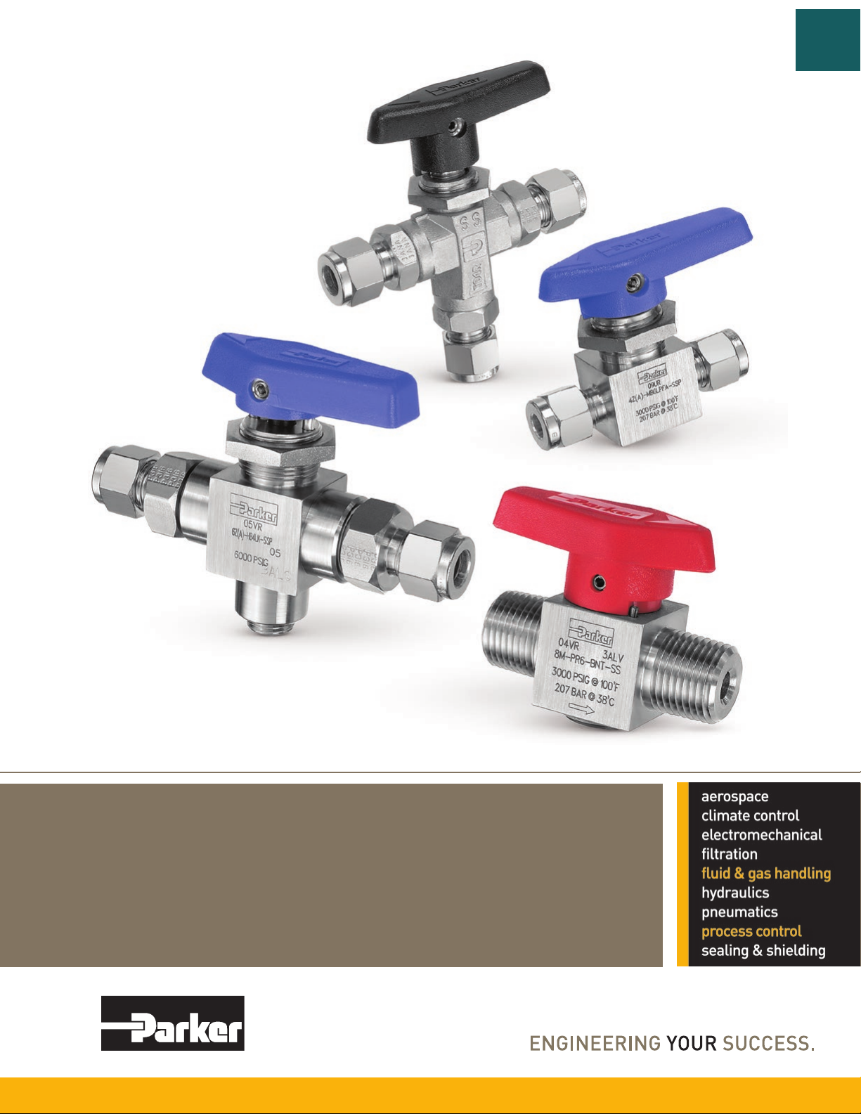
Ball and Plug Valves
Catalog 4121-BV July 2014
Page 2
Go to
Table of
Contents
Parker Hannifin Corporation
Instrumentation Products Division
Jacksonville, AL USA
http://www.parker.com/ipdus
Page 3

Catalog 4121-BV
Table of Contents
Description ............................................................................................................ Page
B Series Ball Valves, 6,000 psi Maximum*
................................................................. 2
Two-Way ................................................................................................................2
Three-Way ............................................................................................................. 4
Go to
Table of
Contents
B
PR Series Rotary Plug Valves, 3,000 psi Maximum*
MB Series Ball Valves, 3,000 psi Maximum*
............................................................ 16
...............................................12
Two-Way In-Line ..................................................................................................17
Two-Way Angle .................................................................................................... 18
Three-Way ........................................................................................................... 18
Four-Way .............................................................................................................20
Five-Way .............................................................................................................. 20
HB Series Ball Valves, 10,000 psi Maximum*
MPB Series Ball Valves, 20,000 psi Maximum*
.......................................................... 22
.......................................................28
Two-Way ..............................................................................................................28
Three-Way ........................................................................................................... 29
SWB Series Ball Valves, 2,500 psi Maximum*
Pneumatic Actuators
.................................................................................................38
......................................................... 32
61 Model .............................................................................................................. 39
62, 63, 64, 65, 66, 68, and 69 Models ................................................................. 39
90° Models (AC, AO and AD) ..............................................................................41
180° Models (ACX and ADX) ............................................................................... 42
Electric Actuators
...................................................................................................... 44
70 Series .............................................................................................................45
80 Series .............................................................................................................46
90 Series .............................................................................................................47
PR
MB
HB
MPB
SWB
Pneu
Act
Elec
Act
B12 Series Ball Valves, 4,000 psi Maximum*
Available End Connections
Offer of Sale
* Actual pressure rating will be determined by the valve configuration, such as body material, seat material, etc.
Contact the factory for more information.
FAILURE OR IMPROPER SELECTION OR IMPROPER USE OF THE PRODUCTS DESCRIBED HEREIN OR RELATED ITEMS CAN CAUSE DEATH, PERSONAL INJURY AND
PROPERTY DAMAGE.
This document and other information from Parker-Hannifin Corporation, its subsidiaries and authorized distributors provide product or system options for further investigation by users
having technical expertise.
The user, through its own analysis and testing, is solely responsible for making the final selection of the system and components and assuring that all performance, endurance,
maintenance, safety and warning requirements of the application are met. The user must analyze all aspects of the application, follow applicable industry standards, and follow the
information concerning the product in the current product catalog and in any other materials provided from Parker or its subsidiaries or authorized distributors.
To the extent that Parker or its subsidiaries or authorized distributors provide component or system options based upon data or specifications provided by the user, the user is responsible
for determining that such data and specifications are suitable and sufficient for all applications and reasonably foreseeable uses of the components or systems.
The items described in this document are hereby offered for sale by Parker-Hannifin Corporation, its subsidiaries or its authorized distributors. This offer and its acceptance are governed by
the provisions stated in the detailed “Offer of Sale” elsewhere in this document or available at www.parker.com/ipdus.
© Copyright 2014 Parker Hannifin Corporation. All Rights Reserved.
...............................................................................................................55
......................................................................................54
WARNING – USER RESPONSIBILITY
........................................................... 52
Offer of Sale
1
Parker Hannifin Corporation
Instrumentation Products Division
Jacksonville, AL USA
http://www.parker.com/ipdus
B12
End
Conn
Page 4
Two-Way B Series Ball Valves
Catalog 4121-BV
Introduction
B
Parker manually, pneumatically, and electrically actuated two-way B Series Ball Valves provide quick 1/4 turn
on-off control of fluids utilized in process and instrumentation applications. A broad selection of valve body, seat,
and seal materials provide a wide range of pressures and temperatures at which the valve may be used.
Go to
Table of
Contents
Features
Free floating ball design provides seat wear
compensation.
Available in 316 stainless steel and brass
construction. Monel® Alloy 400 and Hastelloy®
C-276 construction available upon request.
Micro-finished ball provides a positive seal.
Straight through flow path for minimum
pressure drop.
Bi-directional flow.
Wide variety of US Customary and SI ports.
90° actuation.
Panel mountable.
Adjustable PTFE stem seal can be maintained
in-line.
Handle indicates flow direction.
Low operating torques.
Positive handle stops.
Color coded handles.
Optional pneumatic and electric actuation.
Optional live-loaded PTFE stem seals.
Optional non-adjustable O-ring stem seals.
Optional upstream and downstream drain
models.
Optional stainless steel and extended handles.
Specifications
Pressure Ratings:
Material CWP with PTFE Seats
316 Stainless Steel 6000 psig (414 bar)* 1500 psig (103 bar)
Brass 3000 psig (207 bar) 1500 psig (103 bar)
®
Monel
Alloy 400
B2 and B6:
B8:
Hastelloy
B2 and B6:
B8:
* B6 Series: 6000 psig rating or 4400 psig (303 bar) CWP
®
C-276
B8 Series: 6000 psig rating or 4000 psig (276 bar) CWP
Pressure Rating and Tubing Selection
For working pressures of A-LOK® and CPI™ tube connections,
please see the Instrument Tubing Selection Guide (Bulletin
4200-TS), found in the Technical Section of the Parker
Instrumentation Process Control Binder, or the Parker
Instrument Fitting Installation Manual (Bulletin 4200-B4).
For working pressures of valves with external or internal pipe
threads, please see Catalog 4260, Instrumentation Pipe Fittings.
3000 psig (207 bar)
2000 psig (138 bar)
4000 psig (276 bar)
3000 psig (207 bar)
1500 psig (103 bar)
1500 psig (103 bar)
1500 psig (103 bar)
1500 psig (103 bar)
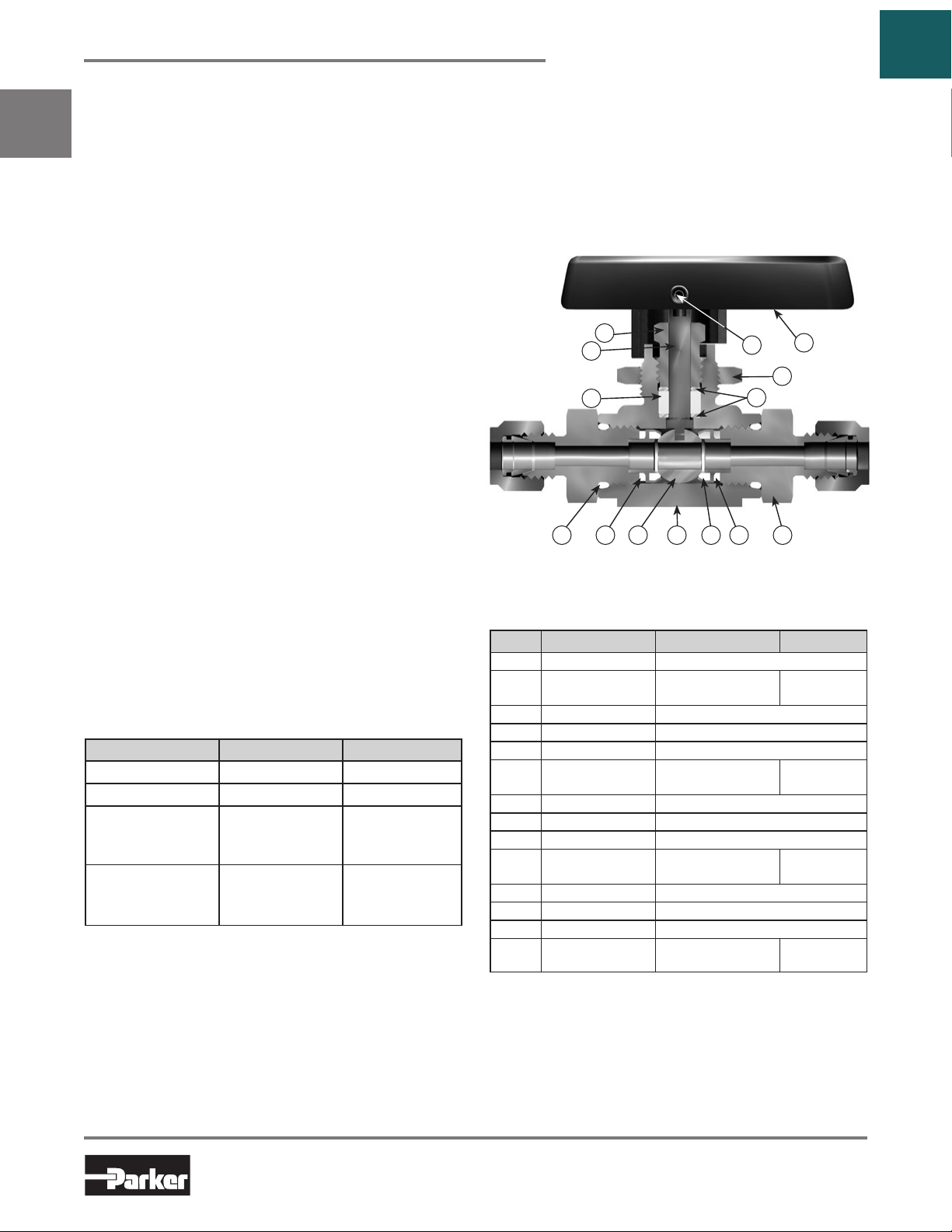
Materials of Construction
7
* 6A
* 6B
1 *
3 * 4 * 5 * 11 *
2B *
9
6C *
2A *
Model Shown: 6A-B6LJ-SSP
Materials of Construction
Item # Part Description Stainless Steel Brass
*1 Connector O-Ring PTFE**
*2A Seat Retainer
*2B Seat PTFE, PCTFE, PEEK
*3 Retainer Seal PTFE**
*4 Ball 316 Stainless Steel
*5 Body
*6A Stem ASTM A 276 Type 316
*6B Stem Seal PTFE**
*6C Stem Washer 316 Stainless Steel
7 Packing Nut
8 Handle Nylon 6/6
9 Handle Set Screw Stainless Steel
10 Panel Nut 316 Stainless Steel
*11 End Connector
* Wetted Parts.
** Optional stem seal and body seal materials are described in the How to
Order section.
Lubrication: Perfluorinated Polyether.
Hastelloy® is a registered trademark of Haynes International.
Monel® Alloy 400 is a registered trademark of Special Metals Corporation.
ASTM A 276
Type 316
ASTM A 351
Grade CF3M
ASTM A 479
Type 316
ASTM A 479
Type 316
8
10
ASTM B 16
Alloy C36000
ASTM B 283
Alloy C37700
ASTM B 453
Alloy C34000
ASTM B 16
Alloy C36000
2
Parker Hannifin Corporation
Instrumentation Products Division
Jacksonville, AL USA
http://www.parker.com/ipdus
Page 5
Catalog 4121-BV
Two-Way B Series Ball Valves
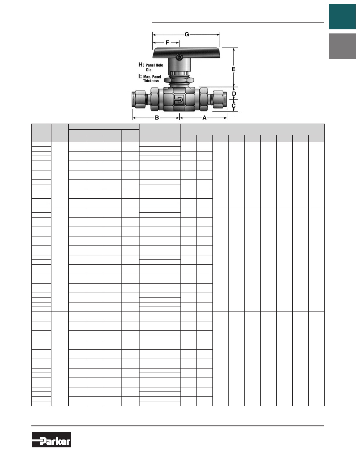
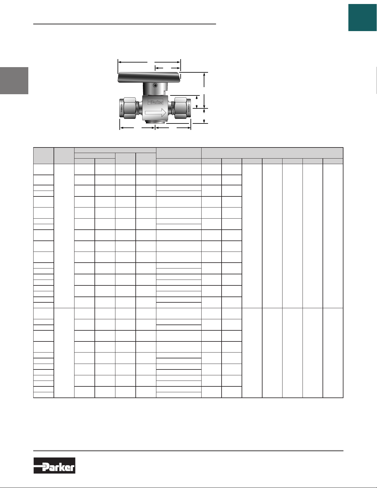
Dimensions & Flow Data
Flow Data
Port
Basic
Size
Part #
1A
1Z 1/16" CPI™
2A
2Z 1/8" CPI™
2F 0.165 4.2 0.93 0.43 1/8" Female NPT
2M 0.165 4.2 0.93 0.43 1/8" Male NPT
4A
4Z 1/4" CPI™
4M 0.165 4.2 0.93 0.43 1/4" Male NPT
M3A
M3Z 3mm CPI™
4A
4Z 1/4" CPI™
4F 0.250 6.4 2.34 0.29 1/4" Female NPT
4M 0.250 6.4 2.34 0.29 1/4" Male NPT
4Q 0.180 4.6 1.03 0.42 1/4" UltraSeal
4V 0.188 4.8 1.04 0.42 1/4" VacuSeal
6A
6Z 3/8" CPI™
6M 0.250 6.4 2.34 0.29 3/8" Male NPT
6Q 0.250 6.4 2.34 0.29 3/8" UltraSeal
M6A
M6Z 6mm CPI™
M8A
M8Z 8mm CPI™
M10A
M10Z 10mm CPI™
6F
8F 0.406 10.3 6.42 0.37 1/2" Female NPT
8A
8Z 1/2" CPI™
8M 0.406 10.3 6.42 0.37 1/2" Male NPT
8Q 0.375 9.5 5.57 0.37 1/2" UltraSeal
8V 0.406 10.3 6.42 0.37 1/2" VacuSeal
12A
12Z 3/4" CPI™
12F 0.406 10.3 6.42 0.37 3/4" Female NPT
M12A
M12Z 12mm CPI™
M16A
M16Z 16mm CPI™
0.052 1.3 0.06 0.45
0.093 2.4 0.21 0.47
B2L
0.165 4.2 0.93 0.43
0.086 2.2 0.18 0.44
0.187 4.7 1.04 0.42
B6L
0.250 6.4 2.34 0.29
0.187 4.7 1.04 0.42
0.250 6.4 2.34 0.42
0.250 6.4 2.34 0.42
0.406 10.3 6.42 0.37 3/8" Female NPT
0.406 10.3 6.42 0.37
B8L
0.406 10.3 6.42 0.37
0.375 9.5 5.57 0.37
0.406 10.3 6.42 0.37
Cv XT*Inch mm Port 1 Port 2 A† B† C D E F G H I
* Tested in accordance with ISA S75.02. Gas flow will be choked when P1- P2 / P1= xT.
† For CPI™ and A-LOK®, dimensions are measured with nuts in the finger tight position
End Connections
1/16" A-LOK
®
1/8" A-LOK
®
1/4" A-LOK
3mm A-LOK
®
1/4" A-LOK
®
3/8" A-LOK
6mm A-LOK
8mm A-LOK
10mm A-LOK
®
1/2" A-LOK
®
3/4" A-LOK
12mm A-LOK
16mm A-LOK
®
1.30
(33.0)
1.36
(34.5)
1.07
(27.2)
1.18
(30.0)
1.48
(37.6)
1.35
(34.3)
®
1.37
(34.8)
1.74
(44.2)
1.51
(38.4)
1.62
(41.1)
1.51
(38.4)
1.75
(44.5)
1.80
(45.7)
1.62
(41.1)
1.51
(38.4)
®
1.75
(44.5)
®
1.78
(45.2)
®
1.81
(46.0)
1.95
(49.5)
2.15
(54.6)
2.34
(59.4)
2.22
(56.4)
1.92
(48.8)
2.21
(56.1)
2.33
(59.2)
2.25
(57.1)
®
2.33
(59.2)
®
2.33
(59.2)
1.30
(33.0)
1.36
(34.5)
1.07
(27.2)
1.18
(30.0)
1.48
(37.6)
1.35
(34.3)
1.37
(34.8)
1.74
(44.2)
1.51
(38.4)
1.62
(41.1)
1.51
(38.4)
1.75
(44.5)
1.80
(45.7)
1.62
(41.1)
1.51
(38.4)
1.75
(44.5)
1.78
(45.2)
1.81
(46.0)
1.95
(49.5)
2.15
(54.6)
2.34
(59.4)
2.22
(56.4)
1.92
(48.8)
2.21
(56.1)
2.33
(59.2)
2.25
(57.1)
2.33
(59.2)
2.33
(59.2)
0.33
(8.4)
0.42
(10.7)
0.69
(17.5)
Model Shown:
4A-B6LJ-SSP
Dimensions
Inches (mm)Orifice
0.33
0.94
(8.4)
(23.9)
0.47
1.53
(11.9)
(38.9)
0.70
1.74
(17.8)
(44.2)
Dimensions in inches/millimeters are
for reference only, subject to change.
0.75
(19.1)
1.00
(25.4)
1.50
(38.1)
1.88
(47.8)
2.50
(63.5)
4.00
(101.6)
0.58
(14.7)
0.77
(19.6)
0.90
(22.9)
Go to
Table of
Contents
B
0.13
(3.3)
0.25
(6.4)
0.38
(9.7)
3
Parker Hannifin Corporation
Instrumentation Products Division
Jacksonville, AL USA
http://www.parker.com/ipdus
Page 6
Three-Way B Series Ball Valves
Catalog 4121-BV
Introduction
B
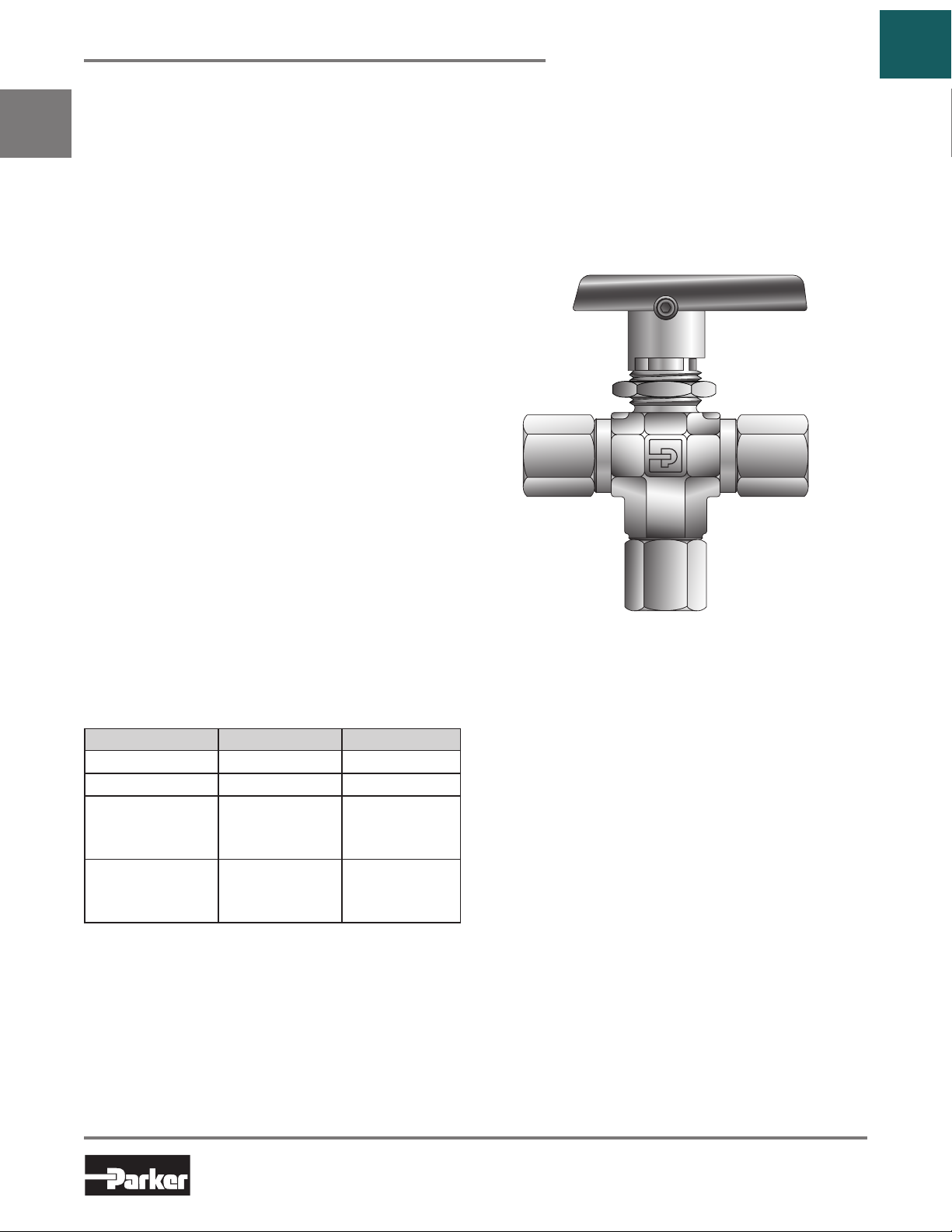
Parker manually, pneumatically, and electrically actuated three-way B Series Ball Valves may be used as diverting
or selecting valves for fluids utilized in process and instrumentation applications. The standard three-way diverter
valve is designed to accept media through the bottom port and direct it out of two outlet ports. When equipped
with spring-loaded seats, the three-way valve may be used as a selector valve, alternately accepting media from
either of two inlet sources (side ports) and directing it through a single outlet (bottom port).
Features
Available in 316 stainless steel and brass
construction. Monel® Alloy 400 and Hastelloy®
C-276 construction available for Diverter Valves
upon request.
Micro-finished ball provides a positive seal.
Wide variety of US Customary and SI ports.
180 degree actuation.
Panel mountable.
Adjustable PTFE stem seal can be maintained
in-line.
Handle indicates flow direction.
Low operating torques.
Positive handle stops.
Color coded handles.
Optional pneumatic and electric actuation.
Optional live-loaded PTFE stem seals.
Optional non-adjustable O-ring stem seals.
Optional stainless steel and extended handles.
Model Shown:
4F-B6XJ2-BP
Go to
Table of
Contents
Diverter Valve Specifications
Pressure Ratings with bottom port as inlet:
Material CWP with PTFE Seats
316 Stainless Steel 6000 psig (414 bar)* 1500 psig (103 bar)
Brass 3000 psig (207 bar) 1500 psig (103 bar)
®
Monel
Alloy 400
B2 and B6: 3000 psig (207 bar) 1500 psig (103 bar)
B8: 2000 psig (138 bar) 1500 psig (103 bar)
Hastelloy
B2 and B6: 4000 psig (276 bar) 1500 psig (103 bar)
B8: 3000 psig (207 bar) 1500 psig (103 bar)
* B6 Series: 6000 psig rating or 4400 psig (303 bar) CWP
Pressure Rating and Tubing Selection
For working pressures of A-LOK® and CPI™ tube connections,
Pressure Rating with side ports as inlet:
150 psig (10 bar)
®
C-276
B8 Series: 6000 psig rating or 4000 psig (276 bar) CWP
Selector Valve Specifications
(Spring Loaded – B6 and B8 models only)
Pressure Rating with bottom port as inlet:
316 Stainless Steel ................... 6000 psig (414 bar) CWP*
Brass ..........................................3000 psig (207 bar) CWP
Pressure Rating with side ports as inlet:
316 Stainless Steel and Brass ....3000 psig (207 bar) CWP
Pressure Rating and Tubing Selection
For working pressures of A-LOK® and CPI™ tube
connections, please see the Instrument Tubing Selection
Guide (Bulletin 4200-TS), found in the Technical Section
of the Parker Instrumentation Process Control Binder, or
the Parker Instrument Fitting Installation Manual (Bulletin
4200-B4).
For working pressures of valves with external or internal
pipe threads, please see Catalog 4260, Instrumentation Pipe
Fittings.
4
Parker Hannifin Corporation
Instrumentation Products Division
Jacksonville, AL USA
http://www.parker.com/ipdus
Page 7
Catalog 4121-BV
Three-Way B Series Ball Valves
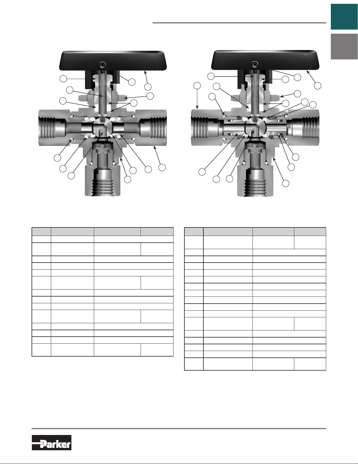
Diverter Valve Selector Valve
Go to
Table of
Contents
B
7
6A *
6B *
1 *
3 *
4 *
5 *
9
6C *
2B *
8
10
2A *
11 *
Model Shown: 4F-B6XJ-SSP Model Shown: 4F-B6XS2-SSP
Materials of Construction
Item # Part Description Stainless Steel Brass
*1 Connector O-Ring PTFE**
*2A Seat Retainer
ASTM A 276
Type 316
*2B Seat PTFE, PCTFE, PEEK
*3 Retainer Seal PTFE**
*4 Ball 316 Stainless Steel
*5 Body
ASTM A 351
Grade CF3M
*6A Stem ASTM A 276 Type 316
*6B Stem Seal PTFE**
*6C Stem Washer 316 Stainless Steel
7 Packing Nut
ASTM A 479
Type 316
8 Handle Nylon 6/6
9 Handle Set Screw Stainless Steel
10 Panel Nut 316 Stainless Steel
*11 End Connector
* Wetted Parts.
** Optional stem seal and body seal materials are described in the How to
Order section.
Lubrication: Perfluorinated Polyether.
ASTM A 479
Type 316
ASTM B 16
Alloy C36000
ASTM B 283
Alloy C37700
ASTM B 453
Alloy C34000
ASTM B 16
Alloy C36000
15 *
3 *
9A *
7 *
9B *
2 *
14 *
10
9C *
1 *
6 *
13
11
8 *
4 *
12
5 *
Materials of Construction
Item # Part Description Stainless Steel Brass
1 Body
ASTM A 351
Grade CF3M
*2 Seat PTFE, PEEK
*3 Seat Retainer ASTM A 276 Type 316
4 Spring Stainless Steel
*5 Seat Retainer Washer 316 Stainless Steel
*6 Back-up Ring PTFE
*7 Connector O-Ring PTFE**
*8 Seat Retainer O-Ring Fluorocarbon Rubber**
*9A Stem ASTM A 276 Type 316
*9B Stem Seal PTFE*
*9C Stem Washer 316 Stainless Steel***
10 Packing Nut
ASTM A 479
Type 316
11 Panel Nut 316 Stainless Steel
12 Handle Nylon 6/6
13 Handle Set Screw Stainless Steel
*14 Ball 316 Stainless Steel
*15 End Connector
* Wetted Parts.
** Optional stem seal and body seal materials are described in the How to
Order section.
Lubrication: Perfluorinated Polyether.
***The lower stem washer material is PEEK for B8 Selector Valves.
Lubrication: Perfluorinated polyether.
ASTM A 479
Type 316
ASTM B 283
Alloy C37700
ASTM B 453
Alloy C34000
ASTM B 16
Alloy C36000
5
Parker Hannifin Corporation
Instrumentation Products Division
Jacksonville, AL USA
http://www.parker.com/ipdus
Page 8

Three-Way B Series Ball Valves
Dimensions & Flow Data
B
Model Shown:
4Z-B6XSPKR-V-SSP
Catalog 4121-BV
Go to
Table of
Contents
Flow Data
Port
Basic
Size
Part #
1A
1Z 1/16" CPI™
2A
2Z 1/8" CPI™
2F 0.165 4.2 0.63 0.59 1/8" Female NPT
2M 0.165 4.2 0.63 0.59 1/8" Male NPT
4A
4Z 1/4" CPI™
4M 0.165 4.2 0.63 0.59 1/4" Male NPT
M3A
M3Z 3mm CPI™
4A
4Z
4F 0.196 5.0 0.87 0.74 1/4" Female NPT
4M 0.196 5.0 0.87 0.74 1/4" Male NPT
4Q 0.180 4.6 0.68 0.67 1/4" UltraSeal
4V 0.188 4.8 0.70 0.69 1/4" VacuSeal
6A
6Z 3/8" CPI™
6M 0.196 5.0 0.87 0.74 3/8" Male NPT
6Q 0.196 5.0 0.87 0.74 3/8" UltraSeal
M6A
M6Z 6mm CPI™
M8A
M8Z 8mm CPI™
M10A
M10Z 10mm CPI™
6F
8A
8Z 1/2" CPI™
8F 0.406 10.3 3.62 0.64 1/2" Female NPT
8M 0.406 10.3 3.62 0.64 1/2" Male NPT
8Q 0.375 9.5 3.46 0.62 1/2" UltraSeal
8V 0.406 10.3 3.62 0.64 1/2" VacuSeal
12A
12Z 3/4" CPI™
12F 0.406 10.3 6.42 0.37 3/4" Female NPT
M12A
M12Z 12mm CPI™
M16A
M16Z 16mm CPI™
0.052 1.3 0.06 0.56
0.093 2.4 0.21 0.64
B2X
0.165 4.2 0.63 0.59
0.086 2.2 0.18 0.63
0.187 4.7 0.70 0.69
0.196 5.0 0.87 0.74
B6X
0.187 4.7 0.70 0.69
0.196 5.0 0.87 0.74
0.196 5.0 0.87 0.74
0.406 10.3 3.62 0.64 3/8" Female NPT
0.406 10.3 3.62 0.64
B8X
0.406 10.3 3.62 0.64
0.375 9.5 3.46 0.62
0.406 10.3 3.62 0.64
Cv X
*Inch mm
T
End Connections
Port 1 Port 2 Port 3 A† B† C D E F G H I
10mm A-LOK
12mm A-LOK
16mm A-LOK
1/16" A-LOK
1/8" A-LOK
1/4" A-LOK
3mm A-LOK
1/4" A-LOK
1/4" CPI™
3/8" A-LOK
6mm A-LOK
8mm A-LOK
1/2" A-LOK
3/4" A-LOK
®
®
®
®
®
®
®
®
®
®
®
®
®
1.30
(33.0)
1.36
(34.5)
1.07
(27.2)
1.18
(30.0)
1.48
(37.6)
1.35
(34.3)
1.37
(34.8)
1.74
(44.2)
1.51
(38.4)
1.62
(41.1)
1.51
(31.8)
1.75
(35.1)
1.80
(45.7)
1.62
(41.1)
1.52
(38.6)
1.75
(44.5)
1.78
(45.2)
1.81
(46.0)
1.95
(49.5)
2.34
(59.4)
2.15
(54.6)
2.22
(56.4)
1.93
(49.5)
2.21
(56.1)
2.33
(59.2)
2.25
(57.1)
2.33
(59.2)
2.33
(56.9)
* Tested in accordance with ISA S75.02. Gas flow will be choked when P1- P2 / P1= xT.
† For CPI™ and A-LOK®, dimensions are measured with nuts in the finger tight position
1.39
(35.3)
1.45
(36.8)
1.15
(29.2)
1.26
(32.0)
1.56
(39.6)
1.43
(36.3)
1.45
(36.8)
1.88
(47.8)
1.65
(41.9)
1.76
(44.7)
1.65
(33.8)
1.89
(37.1)
1.94
(49.3)
1.76
(44.7)
1.65
(41.9)
1.88
(47.8)
1.91
(48.5)
1.95
(49.5)
2.29
(58.2)
2.68
(68.1)
2.49
(63.2)
2.59
(65.8)
2.27
(57.7)
2.55
(65.0)
2.68
(68.1)
2.59
(65.8)
2.67
(67.8)
2.67
(65.5)
0.33
(8.4)
0.47
(11.9)
0.70
(17.8)
Dimensions
Inches (mm)Orifice
0.94
0.75
(19.1)
1.00
(25.4)
1.50
(38.1)
1.88
(47.8)
2.50
(63.5)
4.00
(101.6)
(23.9)
1.53
(38.9)
1.74
(44.2)
Dimensions in inches/millimeters are
for reference only, subject to change.
0.58
(14.7)
0.77
(19.6)
0.90
(22.9)
0.13
(3.3)
0.25
(6.4)
0.38
(9.7)
6
Parker Hannifin Corporation
Instrumentation Products Division
Jacksonville, AL USA
http://www.parker.com/ipdus
Page 9
Catalog 4121-BV
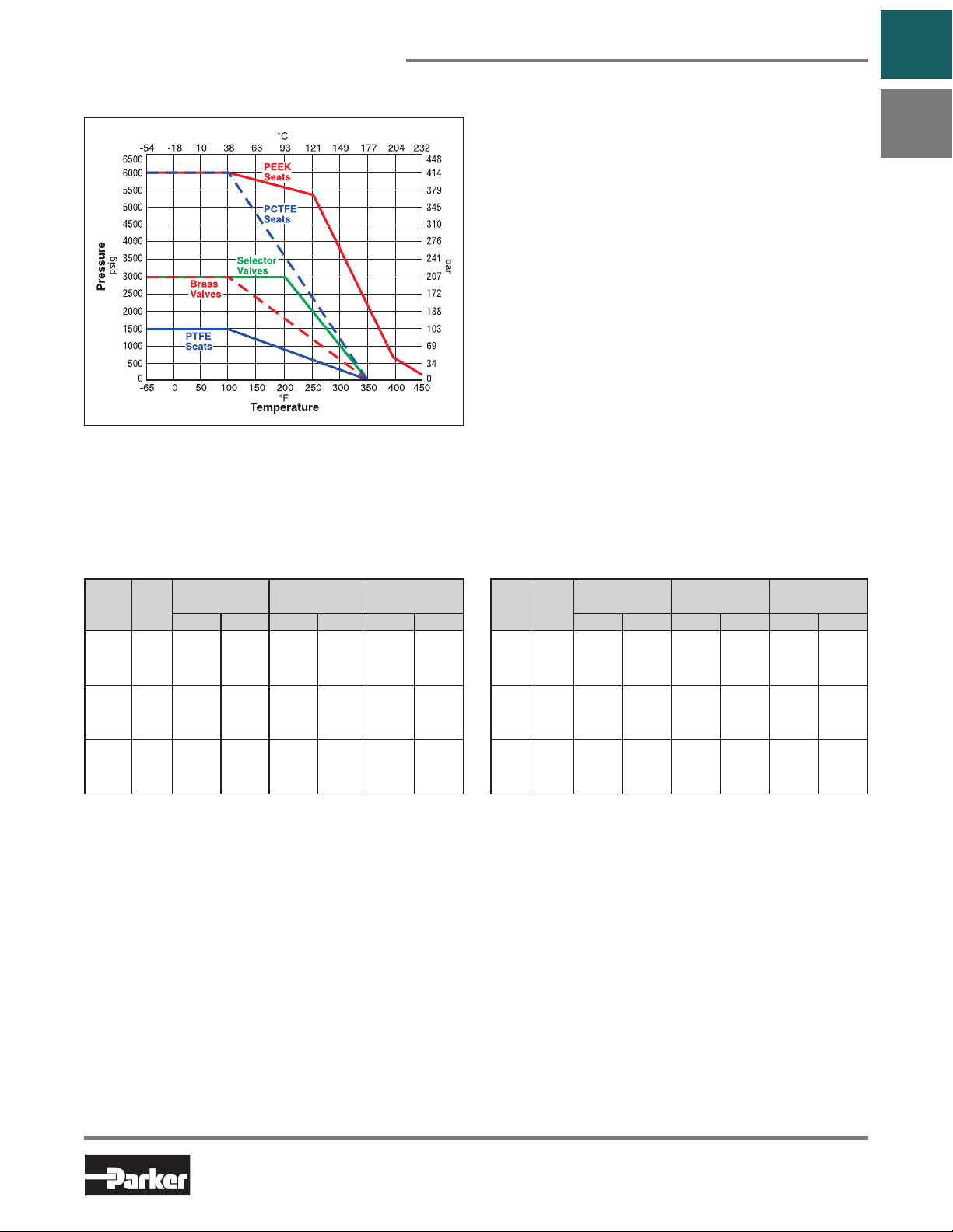
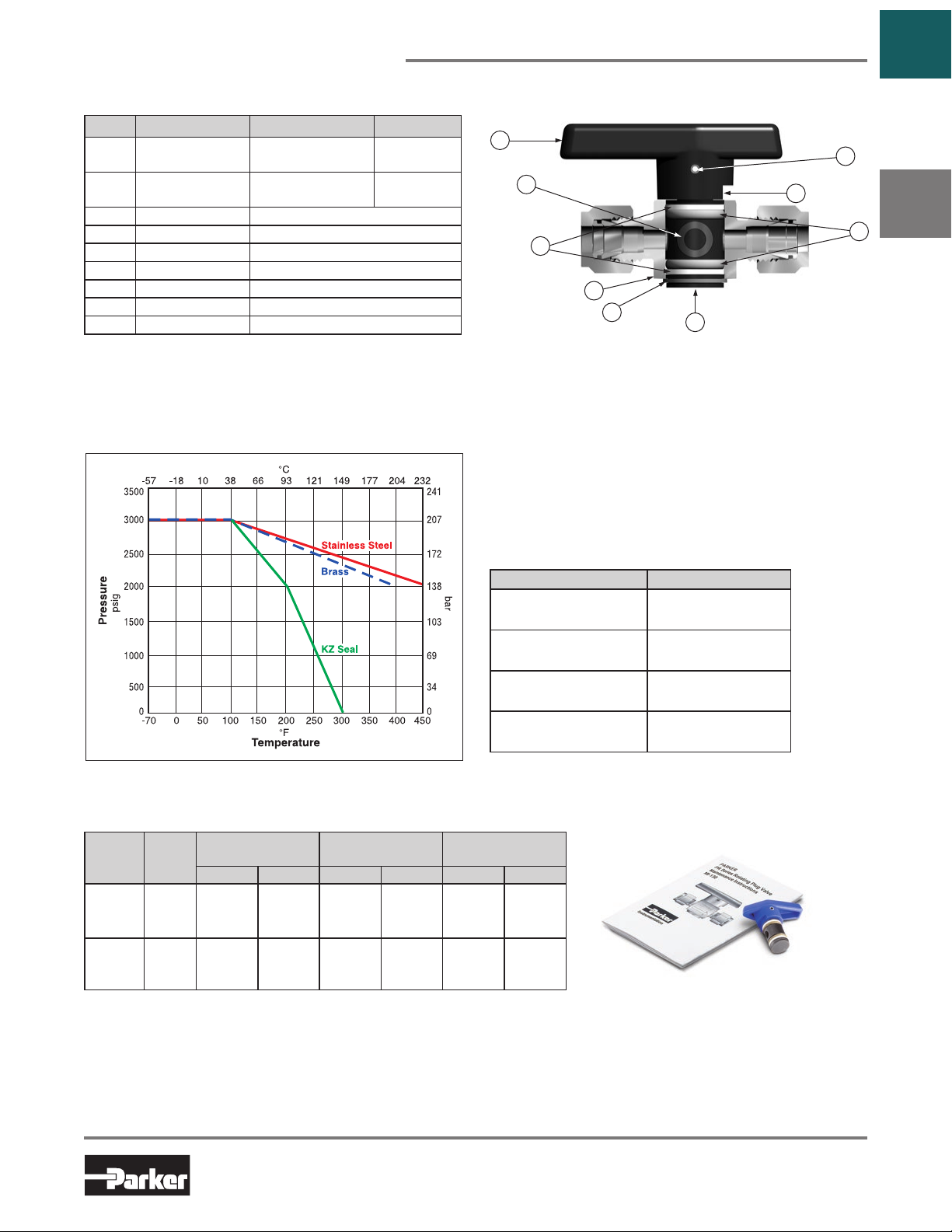
Pressure vs. Temperature
Note: To determine MPa, multiply bar by 0.1
B Series Ball Valves
Note: This Pressure versus Temperature chart
reflects the maximum temperature range of indicated
materials.
When combining seat and seal materials, the most
restrictive temperature rating of the seats or seals
becomes the limiting factor on valve temperature
range.
Elastomeric stem packing and seals are recommended
if the application subjects the valve to thermal cycling.
Please see pages 2 and 4 for maximum pressure ratings.
Temperature Ratings:
PTFE ................................... -65°F to 350°F (-54°C to 177°C)
................................. -65°F to 350°F (-54°C to 177°C)
PCTFE
PEEK
................................... -65°F to 450°F (-54°C to 232°C)
Nitrile Rubber....................... -40°F to 250°F (-40°C to 121°C)
Fluorocarbon Rubber ........... -15°F to 450°F (-26°C to 232°C)
Ethylene Propylene Rubber.... -65°F to 300°F (-54°C to 149°C)
Highly Fluorinated
Fluorocarbon Rubber ......... -15°F to 200°F (-26°C to 93°C)
Go to
Table of
Contents
B
Flow Calculations with 1000 psig (69 bar) Inlet Pressure
Two-Way Three-Way
Valve
Max.
Series
B2L 0.93
B6L 2.34
B8L 6.42
Pressure Drop
∆P
Cv
psig bar gpm m3/hr scfm m3/hr
10 0.7 2.9 0.7 92.4 156.2
50 3.5 6.6 1.5 200.3 338.3
100 6.9 9.3 2.1 272.0 458.9
10 0.7 7.4 1.7 231.7 391.5
50 3.5 16.5 3.8 494.2 834.7
100 6.9 23.4 5.3 657.0 1107.9
10 0.7 20.3 4.6 637.1 1076.8
50 3.5 45.4 10.3 1373.6 2320.3
100 6.9 64.2 14.6 1852.3 3124.8
Water
@ 60°F (16°C)
Air
@ 60°F (16°C)
Valve
Series
B2X 0.63
B6X 0.87
B8X 3.62
Pressure Drop
Max.
Cv
∆P
psig bar gpm m3/hr scfm m3/hr
10 0.7 2.0 0.5 62.7 106.0
50 3.5 4.5 1.0 137.1 231.7
100 6.9 6.3 1.4 188.4 317.9
10 0.7 2.8 0.6 86.7 146.6
50 3.5 6.2 1.4 190.5 321.8
100 6.9 8.7 2.0 263.2 444.4
10 0.7 11.5 2.6 360.6 609.5
50 3.5 25.6 5.9 789.7 1343.5
100 6.9 36.2 8.2 1087.4 1836.6
Water
@ 60°F (16°C)
Air
@ 60°F (16°C)
7
Parker Hannifin Corporation
Instrumentation Products Division
Jacksonville, AL USA
http://www.parker.com/ipdus
Page 10
B Series Ball Valves
Port 1
Port 2
Port 1
Port 2
Port 3
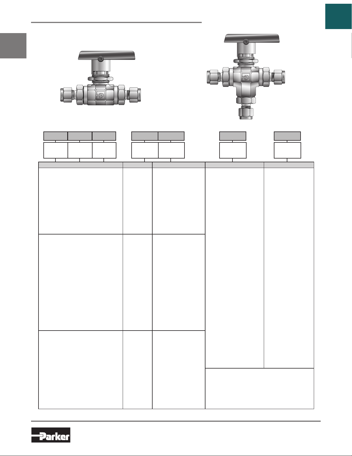
How to Order
B
Model Shown: 6A-B6LJ2-SSP
Catalog 4121-BV
Model Shown:
6A-B6XJ2-SSP
Go to
Table of
Contents
– –
Port 3Port 2Port 1
Ports 1, 2 and 3 Valve Series Seat Material Seal Material Body Material
1A
1/16" A-LOK
1Z 1/16" CPI™
2A 1/8" A-LOK®
2Z 1/8" CPI™
2F 1/8" Female NPT
2M 1/8" Male NPT
4A 1/4" A-LOK
4Z 1/4" CPI™
4M 1/4" Male NPT
M3A 3mm A-LOK
M3Z 3mm CPI™
4A
1/4" A-LOK
4Z 1/4" CPI™
4F 1/4" Female NPT
4M 1/4" Male NPT
4Q 1/4" UltraSeal
4V 1/4" VacuSeal
6A 3/8" A-LOK
6Z 3/8" CPI™
6M 3/8" Male NPT
6Q 3/8" UltraSeal
M6A 6mm A-LOK
M6Z 6mm CPI™
M8A 8mm A-LOK
M8Z 8mm CPI™
M10A 10mm A-LOK
M10Z 10mm CPI™
6F 3/8" Female NPT
8A 1/2" A-LOK
8Z 1/2" CPI™
8F 1/2" Female NPT
8M 1/2" Male NPT
8Q 1/2" UltraSeal
8V 1/2" VacuSeal
12Z 3/4" CPI™
12F 3/4" Female NPT
M12A 12mm A-LOK
M12Z 12mm CPI™
M16A 16mm A-LOK®
M16Z 16mm CPI™
See examples on page 9. See pages 10 and 11 for information about How to Order Options and Maintenance Kits.
®
®
®
®
®
®
®
®
®
Valve
Series
B2L
B2X
B6L
B6X
B8L
B8X
Seat
Material
J
PTFE
J2 PCTFE
J
PTFE
J2 PCTFE
S2 Spring-Loaded
PCTFE
PKR PTFE Lubricated
PEEK
SPKR Spring-Loaded
PTFE Lubricated
PEEK
J
PTFE
J2 PCTFE
S2 Spring-Loaded
PCTFE
PKR PTFE Lubricated
PEEK
SPKR Spring-Loaded
PTFE Lubricated
PEEK
Seal
Material
(Blank) PTFE
V Fluorocarbon Rubber
EPR Ethylene Propylene
Rubber
BN Nitrile Rubber
KZ Highly Fluorinated
Fluorocarbon Rubber
LT Live-Loaded PTFE
Packing with PTFE
Seals
VLT Live-Loaded PTFE
Packing with Fluoro
carbon Rubber Seals
EPRLT Live-Loaded PTFE
Packing with Ethylene
Propylene Rubber
Seals
BNLT Live-Loaded PTFE
Packing with Nitrile
Rubber Seals
KZLT Live-Loaded PTFE
Packing with Highly
Flourinated Fluoro carbon Rubber Seals
Notes:
1. Panel Mounting Nut supplied with each valve.
Various port combinations are available.
2. See How to order.
3. VacuSeal and UltraSeal are not available in
Brass.
4. 12F (3/4" Female NPT) not panel mountable.
–
SSP 316 Stainless Steel
BP Brass
MP Monel® Alloy 400
HCP Hastelloy® C-276
Body
Material
8
Parker Hannifin Corporation
Instrumentation Products Division
Jacksonville, AL USA
http://www.parker.com/ipdus
Page 11
Catalog 4121-BV
How to Order (Continued)
Examples: Two-Way Valves
Examples: Three-Way Diverter Valves
–
–
Examples: Three-Way Selector Valves
–
–
B Series Ball Valves
Go to
Table of
Contents
B
4Z
Port 1
Describes a B6L ball valve with a 1/4" CPI™ end connection for port 1 and a 1/4" female NPT end
connection for port 2, PTFE seats, PTFE stem and body seals, brass construction, with a panel mounting
nut.
8A
Port 1
Describes a B8L ball valve with a 1/2" A-LOK® end connections for ports 1 and 2, PTFE seats, Nitrile
rubber stem and body seals, stainless steel construction, with a panel mounting nut.
* Note: If ports 1 and 2 are the same, eliminate the port 2 designator.
M3A
Port 1
Describes a B2L ball valve with 3mm A-LOK® end connections for ports 1 and 2, PCTFE seats,
fluorocarbon rubber body seals, PCTFE packing, stainless steel construction, with a panel mounting nut.
* Note: If ports 1 and 2 are the same, eliminate the port 2 designator.
4Z
4F
Port 2
*
Port 2
*
Port 2
4Z
–
Valve Series
Valve Series
4F
B6L
Valve Series
B8L
B2L
B6X
J
Seat Material
J
Seat Material
J2
Seat Material
–– –
–– –
J2
–
Seal Material
BN
Seal Material
VLT
Seal Material
–
Body Material
V
BP
SSP
Body Material
SSP
Body Material
BP
Port 1
Describes a B6X ball valve with 1/4" CPI™ end connections for side ports 1 and 2, 1/4" female NPT end
connection for bottom port 3, PCTFE seats, fluorocarbon rubber stem and body seals, brass construction,
and a panel mounting nut.
2Z
Port 1
Port 2
*
Port 2
Port 3
*
Port 3
Valve Series
B2X
Valve Series
Seat Material
J
Seat Material
Seal Material
–
Seal Material
Body Material
SSP
Body Material
Describes a B2X ball valve with 1/8" CPI™ end connections for ports 1, 2, and 3, PTFE seats, PTFE
stem and body seals, stainless steel construction, and a panel mounting nut.
* Note: If ports 1, 2, and 3 are the same, eliminate the port 2 and port 3 designators.
4M
Port 1
Describes a B6X ball valve with 1/4" male NPT end connections for side ports 1 and 2, 1/4" female NPT
end connection for bottom port 3, spring-loaded PCTFE seats, ethylene propylene rubber stem and body
seals, stainless steel construction, and a panel mounting nut.
8A
Port 1
Describes a B8X ball valve with 1/2" A-LOK® end connections for ports 1, 2, and 3, spring-loaded PCTFE
seats, Nitrile rubber body seals, live loaded PTFE packing, stainless steel construction, and a panel
mounting nut.
* Note: If ports 1, 2, and 3 are the same, eliminate the port 2 and port 3 designators.
4M
Port 2
*
Port 2
4F
Port 3
*
Port 3
B6X
Valve Series
B8X
Valve Series
S2
Seat Material
S2
Seat Material
–
–
EPR
Seal Material
BNLT
Seal Material
SSP
Body Material
SSP
Body Material
9
Parker Hannifin Corporation
Instrumentation Products Division
Jacksonville, AL USA
http://www.parker.com/ipdus
Page 12
B Series Ball Valves
Options
B
Catalog 4121-BV
Go to
Table of
Contents
Round Handle
Actuator Options
Double Acting (61AD)
Pneumatic Actuator
Spring Returns (61AC & AO)
Pneumatic Actuator
Lock-Out Handle
70, 80 & 90 Series
Electric Actuator
Live-Loaded Stem SealsO-Ring Stem Seals
Two-Way Valve Upstream and Downstream Drain Options
For draining upstream or downstream media on two-way valves at pressures below 150 psig (10 bar), add the
suffix –VBU (Vented Ball Upstream) or –VBD (Vented Ball Downstream). Example: 4Z-B6LJ-SSP-VBU. This
option is also suitable to vent the ball cavity in vacuum applications. For pressures up to 3,000 psig (207 bar),
select S2 or SPKR spring-loaded seats and add the suffix –VBU (Vented Ball Upstream) or –VBD (Vented Ball
Downstream). Example: 4Z-B6LS2-SSP-VBU
Note: VBD and VBU are ball cavity vents only.
10
Parker Hannifin Corporation
Instrumentation Products Division
Jacksonville, AL USA
http://www.parker.com/ipdus
Page 13

Catalog 4121-BV
B Series Ball Valves
How to Order Options Examples
Lock-Out Devices: Add the suffix LD to the end of the part number to order directly on the valve. 4F-B6LJ2-BN-SSP-LD
For field installation, simply substitute the correct valve series number after LD. LD-B8L
Colored Lever Handles: Add the designator corresponding to the correct handle as a suffix to the part number
(black is standard). W = white, B = blue, G = green, R = red, Y
Colored Round Handles: Add the designator corresponding to the correct handle as a suffix to the part number.
S = Black, S-W = white, S-B = blue, S-G = green, S-R = red, S-Y = yellow. M6A-B6XPKR-SSP-S-G
NOTE: Round handles are not recommended for B8 valves with PEEK seats.
Metal Oval Handles: Add the designator corresponding to the correct handle as a suffix to the valve part number.
OVSS = stainless steel, SA
NOTE: Not available in size 2.
Stainless Steel Handles: Add the suffix -ST to the end of the part number (B6 and B8 only). 4F-B6LJ-SSP-ST
Pneumatic Actuators: For detailed actuator information, refer to the Pneumatic Actuators section of this catalog.
For factory assembly, add the actuator part number as the suffix to the valve part number. 2F-B2XJ2-V-SSP-61ACX-2
For field installation, specify the actuator desired. 61ACX-2
The appropriate mounting hardware may be obtained by adding the valve series and actuator size to the prefix MK-. MK-B2X-61
Electric Actuators: For detailed actuator information refer to the Electric Actuators section of this catalog.
For factory assembly, add the actuator part number as the suffix to the valve part number. 8A-B8LPKR-BN-SS-71A
For field installation, specify the actuator desired. 71A
The appropriate mounting hardware may be obtained by adding the valve series and actuator series to the prefix MK-. MK-B8L-70
Oxygen Cleaning: Add the suffix -C3 to the end of the part number to receive valves cleaned and asembled
for oxygen service in accordance with Parker Specification ES8003. 4A-B6LJ-EPR-SSP-C3
Electron Beam Welded End Connections: For tamper resistant valves, add the suffix -EBW to the end of the
part number of stainless steel valves to have end connections electron beam welded. M6A-B6LSPKR-V-SSP-EBW
Fillet Weld End Connections: For seal welded valves, add the suffix -FW to the end of the part number of the
stainless steel valves to have the end connections seal welded to the body. 8Z-B8LJ2-SSP-FW
Grounding Spring: To obtain B6 and B8 series valves with a grounding spring, add the suffix -SPG to the end
of the part number. 8A-B8LJ2-SSP-SPG
= oval aluminum. 8F-B8LPKR-SSP-OVSS
= yellow. M6A-B6XPKR-SSP-G
Go to
Table of
Contents
B
How to Order Maintenance Kits
Colored Round Handle Kits: Series-Handle-Color. (Example consists of a green handle and handle screw.) B6-RD-HANDLE-GREEN
NOTE: Stainless Steel kits not available in size 2.
Stainless Steel Handle Kits: Series-Handle-SS. (Example consists of a stainless steel handle and handle screw.) B8-HANDLE-SS
Colored Lever Handle Kits: Series-Handle-Color. (Example consists of a red handle and handle screw.) B6-HANDLE-RED
Two-way Valve Seal Kits:
PTFE Stem Seal Kits: Kit-Valve Series and Seat Material-Body Material. KIT-B2LJ-SS
(Consists of one PTFE stem seal, two stem seal washers, two encapsulated PTFE ball seats, two end connector
PTFE seals, one assembly mandrel, maintenance instructions.)
Elastomeric Stem Seal Kits: Kit-Valve Series and Seat Material-Elastomer Material-Body Material. KIT-B2LJ2-BN-SS
(Consists of two stem seal Nitrile rubber O-rings, two PTFE back-up rings, two stem seal washers, two encapsulated PCTFE ball seats,
two end connector Nitrile rubber O-ring seals, two seat retainer Nitrile rubber O-ring seals, stem glands and maintenance instructions.)
Diverter Valve Seal Kits:
PTFE Stem Seal Kits: Kit-Valve Series and Seat Material-Body Material. KIT-B6XPKR-SS
(Consists of one PTFE stem seal, two stem seal washers, two encapsulated PEEK ball seats, three end connector
PTFE seals, one assembly mandrel, maintenance instructions.)
Elastomeric Stem Seal Kits: Kit-Valve Series and Seat Material-Elastomer-Body Material. KIT-B6XJ-V-SS
(Consists of two stem seal fluorocarbon rubber O-rings, two PTFE back-up rings, two stem seal washers, two
encapsulated PTFE ball seats, three end connector fluorocarbon rubber O-ring seals, two seat retainer fluorocarbon
rubber O-ring seals, stem glands and maintenance instructions.)
Selector Valve Seal Kits:
PTFE Stem Seal Kits: Kit-Valve Series and Seat Material. KIT-B6XS2
(Consists of one PTFE stem seal, two stem seal washers, two encapsulated spring-loaded PCTFE ball seats, two
seat retainer fluorocarbon rubber O-rings, three end connector PTFE seals, one assembly mandrel, maintenance instructions.)
Elastomeric Stem Seal Kits: Kit-Valve Series and Seat Material-Elastomer. KIT-B6XSPKR-V
(Consists of two stem seal fluorocarbon rubber O-rings, two PTFE back-up rings, two stem seal washers, two
encapsulated spring-loaded PEEK ball seat assemblies, three end connector fluorocarbon O-ring seals, two seat
retainer fluorocarbon rubber O-rings, stem glands and maintenance instructions.)
Live-loaded Seal Kits:
Kit-Valve Series and Seat Material-Seal Material-Body Material. KIT-B6LJ2-BNLT-SS
(Consists of one live-loaded PTFE stem packing, two packing springs (B8 series valves have four springs), three packing washers, two PCTFE
encapsulated ball seats, two Nitrile rubber end connector O-ring seals, two Nitrile rubber seat retainer O-ring seals, maintenance instructions.)
11
Parker Hannifin Corporation
Instrumentation Products Division
Jacksonville, AL USA
http://www.parker.com/ipdus
Page 14
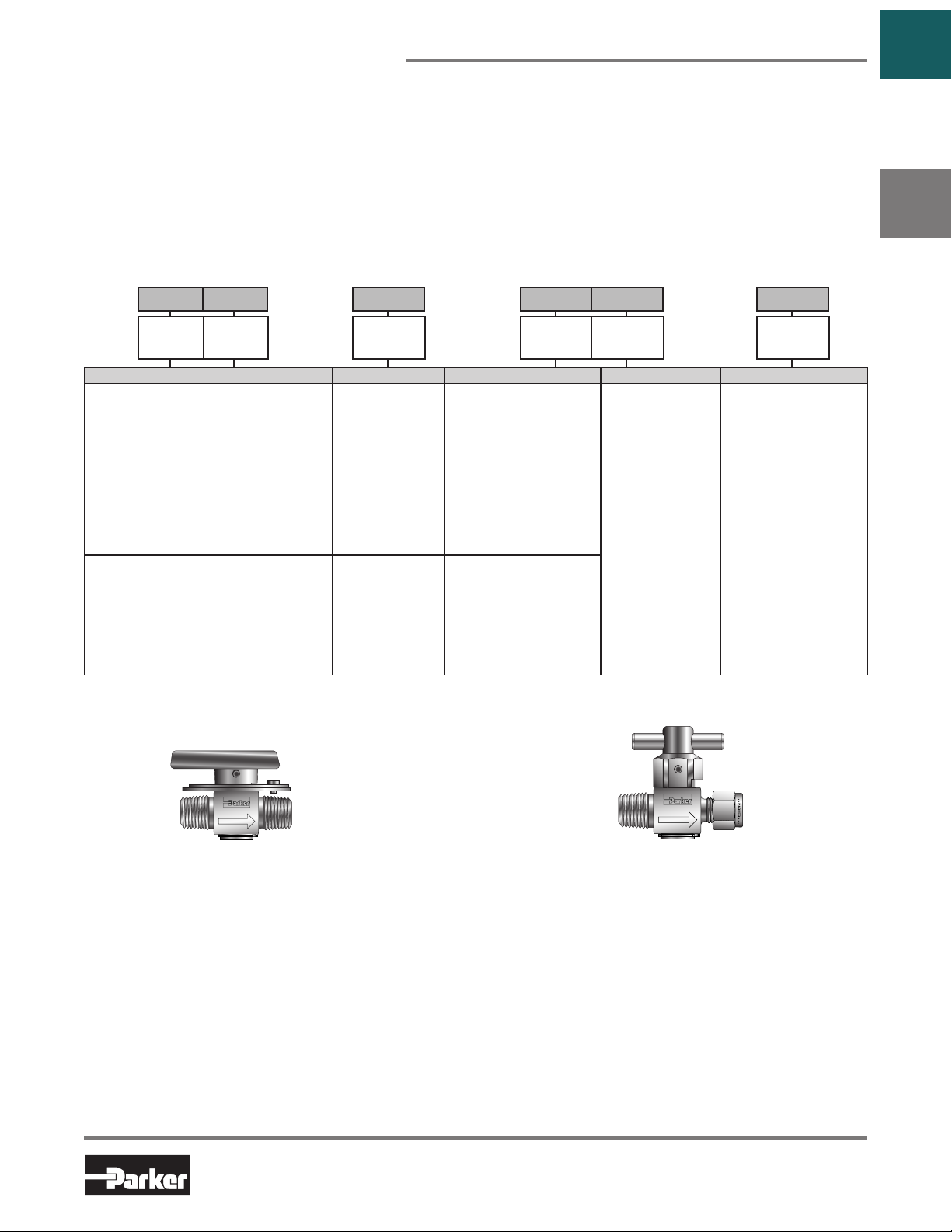
PR Series Rotary Plug Valves
Catalog 4121-BV
Introduction
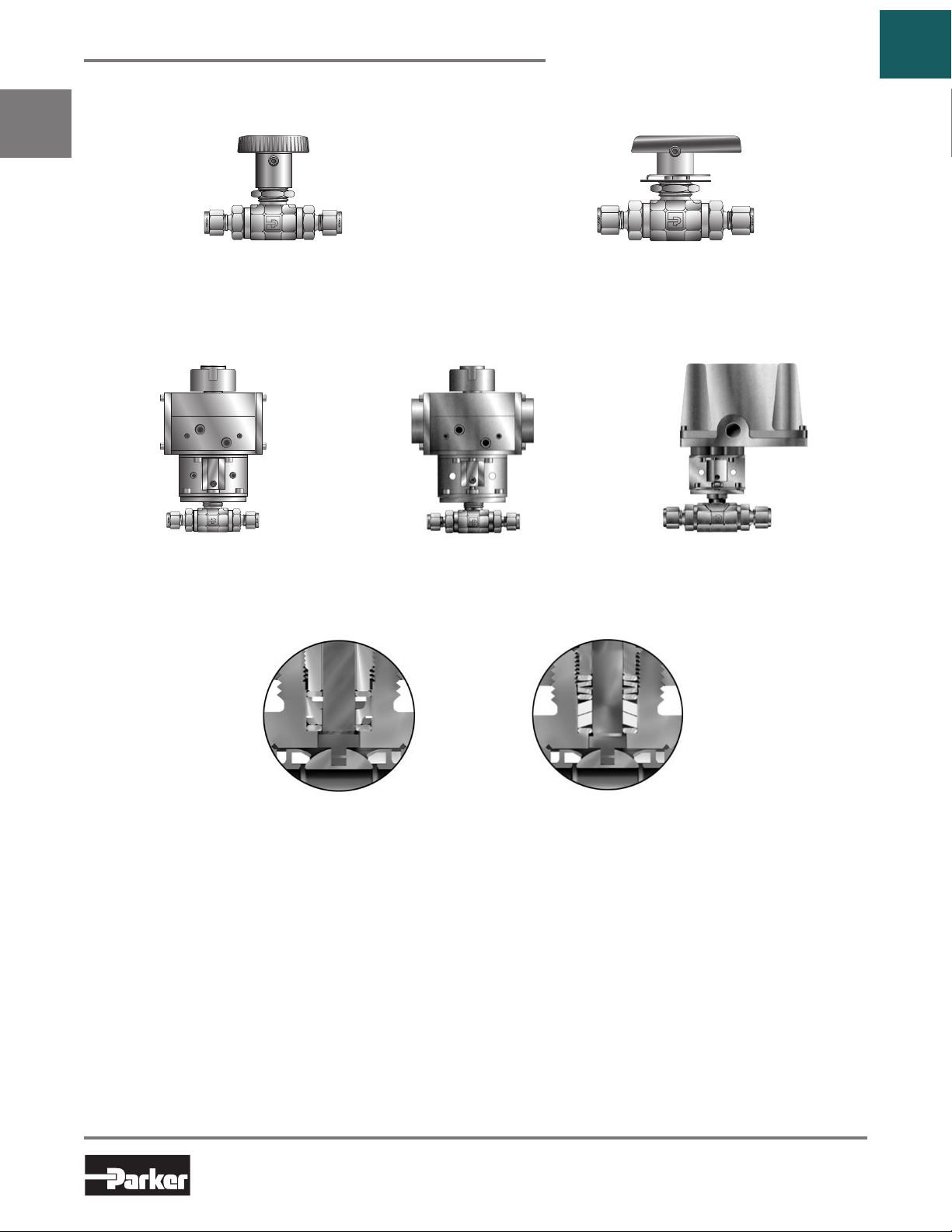
Parker PR Series Plug Valves provide positive leak tight shut-off, high flow capacity, and quick quarter-turn
operation in a compact attractive package. The patented blow-out resistant seat design offers reliable sealing
technology at all operating pressures. In addition to on-off actuation, the plug design allows forward flow throttling.
A selection of valve seat and seal materials may be chosen for media compatibility and performance over a broad
PR
range of temperatures. The pressure balanced atmospheric seals are backed by PTFE rings to enhance their
performance and increase cycle life.
Features
Patented blow-out resistant seat design
Pressures up to 3,000 psig (207 bar) CWP
Quarter-turn operation
Reliable simple design
Straight-through flow
Stainless steel and brass construction
Nitrile, ethylene propylene, fluorocarbon, and highly
fluorinated fluorocarbon rubber seats and seals
Open
Go to
Table of
Contents
PTFE back-up rings on atmospheric seals
Low operating torque
Minimum pressure drop
Throttling capability
Positive handle stops
Color coded fracture resistant nylon handles with
directional flow indication
Easy to service
100% factory tested
Options include lock-out devices, downstream
venting, and both stainless steel and T-bar handles
Specifications
Pressure Ratings:
Normal Flow Direction: 3000 psig (207 bar) CWP
Reverse Flow Direction: 150 psig (10 bar)
Downstream Vent Option: 150 psig (10 bar)
Closed
Model Shown: 4A-PR4-VT-SS
U.S. Patent 5,234,193
12
Parker Hannifin Corporation
Instrumentation Products Division
Jacksonville, AL USA
http://www.parker.com/ipdus
Page 15
Catalog 4121-BV
Materials of Construction
Item # Part Description Stainless Steel Brass
1 Body
2 Plug*
3 Seat** Fluorocarbon Rubber
4 O-Ring Seals** Fluorocarbon Rubber
5 Back-up Rings PTFE
6 Handle Nylon 6/6
7 Handle Pin 316 Stainless Steel
8 Body Pin 316 Stainless Steel (not shown)
9 Retaining Ring 316 Stainless Steel
* Plugs are PTFE color coated – Stainless steel plugs are black;
Brass plugs are brown.
** Optional Seat and O-ring seal materials are available.
Lubrication: Perfluorinated polyether
ASTM A 479
Type 316
ASTM A 479
Type 316
ASTM B 16
Alloy C36000
ASTM B 16
Alloy C36000
Pressure vs. Temperature
PR Series Rotary Plug Valves
6
7
3
5
1
9
2
Model Shown: 4A-PR4-VT-SS
Note: This Pressure versus Temperature chart reflects the
maximum temperature range of indicated body materials.
The temperature rating of the elastomer seals become the
limiting factor on temperature range.
8
Go to
Table of
Contents
PR
4
Temperature Ratings
Material Temperature Rating
Nitrile Rubber
Fluorocarbon Rubber
Highly Fluorinated
Fluorocarbon Rubber
Ethylene Propylene
Rubber
Note: To determine MPa, multiply bar by 0.1
Flow Calculations with 1000 psig (69 bar) Inlet Pressure
Valve
Series
PR4 1.24
PR6 3.19
Max.
Cv
Water
Pressure Drop ∆P
psig bar gpm m3/hr scfm m3/hr
10 0.7 3.9 0.9 123.1 209.6
50 3.4 8.8 2.0 265.9 446.3
100 6.9 12.4 2.8 359.6 607.0
10 0.7 10.1 2.3 315.7 533.5
50 3.4 22.6 5.1 672.3 1128.2
100 6.9 31.9 7.2 891.6 1504.1
@ 60°F (16°C)
Air
@ 60°F (16°C)
-30°F to 225°F
(-34°C to 107°C)
-10°F to 450°F
(-23°C to 232°C)
-10°F to 300°F
(-23°C to 149°C)
-70°F to 275°F
(-57°C to 135°C)
Kits
Plug Kits – Specify the combination of valve series, seal material, plug material, and handle color (if applicable).
Example: KIT-PR4-VT-SS-Y. This kit consists of a PR4 stainless steel plug with fluorocarbon rubber seat and seal
elastomers, PTFE back-up rings, yellow handle, and handle pin.
Seal Kits – Specify the combination of valve series and seal material.
Example: KIT-PR4-BN. This kit consists of a PR4 Nitrile rubber seat and seal elastomers and PTFE back-up rings.
13
Parker Hannifin Corporation
Instrumentation Products Division
Jacksonville, AL USA
http://www.parker.com/ipdus
Page 16
PR Series Rotary Plug Valves
Flow Data / Dimensions
G
PR
A B
Catalog 4121-BV
Go to
Table of
Contents
F
E
D
C
Model Shown: 4A-PR4-VT-B
Port
Size
M3A
M3Z 3mm CPI™
M6A
M6Z 6mm CPI™
M8A
M8Z 8mm CPI™
M8A
M8Z 8mm CPI™
M10A
M10Z 10mm CPI™
M12A
M12Z 12mm CPI™
Basic
Part #
2F
2M 0.172 4.4 1.02 0.39 1/8" Male NPT
2A
2Z 1/8" CPI™
4F 0.193 4.9 1.24 0.39 1/4" Female NPT
4M 0.193 4.9 1.24 0.39 1/4" Male NPT
4A
4Z 1/4" CPI™
4Q 0.187 4.7 1.18 0.41 1/4" UltraSeal
4V 0.187 4.7 1.18 0.41 1/4" VacuSeal
6M 0.193 4.9 1.24 0.39 3/8" Male NPT
6A
6Z 3/8" CPI™
4F
6A
6Z 3/8" CPI™
8F 0.281 7.1 3.19 0.28 1/2" Female NPT
8M 0.281 7.1 3.19 0.28 1/2" Male NPT
8A
8Z 1/2" CPI™
PR4
PR6
0.193 4.9 1.24 0.39 1/8" Female NPT
0.093 2.4 0.22 0.48
0.187 4.7 1.18 0.41
0.193 4.9 1.24 0.39
0.086
0.188 4.8 1.18 0.41
0.193 4.9 1.24 0.48
0.281 7.1 3.19 0.28 1/4" Female NPT
0.281 7.1 3.19 0.28
0.281 7.1 3.19 0.28
0.250 6.4 2.84 0.29
0.281 7.1 3.19 0.28
0.281 7.1 3.19 0.28
Flow Data
Cv XT *Inch mm Port 1 Port 2 A† B† C D E F G
2.2 0.15 0.48
End Connections
®
1/8" A-LOK
®
1/4" A-LOK
®
3/8" A-LOK
3mm A-LOK
6mm A-LOK
8mm A-LOK
®
3/8" A-LOK
®
1/2" A-LOK
8mm A-LOK
10mm A-LOK
12mm A-LOK
0.89
(22.6)
0.77
®
®
®
®
®
®
(19.6)
1.00
(25.4)
1.05
(26.7)
0.96
(24.4)
1.09
(27.7)
0.85
(21.7)
1.02
(25.9)
0.94
(23.9)
1.14
(29.0)
0.98
(24.9)
1.08
(27.4)
1.11
(28.2)
1.19
(30.2)
1.33
(33.8)
1.44
(36.6)
1.32
(33.5)
1.44
(36.6)
1.30
(33.0)
1.34
(34.0)
1.47
(37.3)
* Tested in accordance with ISA S75.02. Gas flow will be choked when P1 - P2 / P1 = xT .
† For CPI™ and A-LOK®, dimensions are measured with nuts in the finger tight position.
0.89
(22.6)
0.77
(19.6)
1.00
(25.4)
1.05
(26.7)
0.96
(24.4)
1.09
(27.7)
0.85
(21.7)
1.02
(25.9)
0.94
(23.9)
1.14
(29.0)
0.98
(24.9)
1.08
(27.4)
1.11
(28.2)
1.19
(30.2)
1.33
(33.8)
1.44
(36.6)
1.32
(33.5)
1.44
(36.6)
1.30
(33.0)
1.34
(34.0)
1.47
(37.3)
0.46
(11.7)
0.67
(17.0)
Dimensions
Inches (mm)Orifice
0.38
(9.7)
0.56
(14.2)
1.07
(27.2)
1.49
(37.8)
0.75
(19.1)
0.99
(25.1)
Dimensions in inches/millimeters are
for reference only, subject to change.
1.88
(47.8)
2.40
(61.0)
14
Parker Hannifin Corporation
Instrumentation Products Division
Jacksonville, AL USA
http://www.parker.com/ipdus
Page 17
Catalog 4121-BV
PR Series Rotary Plug Valves
How to Order
The correct part number is easily derived from the following example and ordering chart. The six product
characteristics required are coded as shown in the chart.
* Note: If the inlet and outlet ports are the same, eliminate the outlet port designator.
The following example describes a PR Series rotary plug valve equipped with 1/4" CPI™ compression inlet and
outlet ports, Nitrile seals, PTFE back-up rings, and stainless steel construction.
Example:
4Z – PR4 – BNT – SS
–
– –
Go to
Table of
Contents
PR
Inlet
Port*
Inlet and Outlet Ports* Valve Series Seal Material Back-Up Rings Body Material
2A
1/8" A-LOK®
2Z 1/8" CPI™
2F 1/8" Female NPT
2M 1/8" Male NPT
4A 1/4" A-LOK
4Z 1/4" CPI™
4F 1/4" Female NPT
4M 1/4" Male NPT
4Q 1/4" UltraSeal
4V 1/4" VacuSeal
4F 1/4" Female NPT
6A 3/8" A-LOK
6Z 3/8" CPI™
8A 1/2" A-LOK
8Z 1/2" CPI™
8F 1/2" Female NPT
8M 1/2" Male NPT
* If the inlet and outlet ports are the same, eliminate the outlet port designator.
®
®
®
Outlet
Port*
6M 3/8" Male NPT
6A 3/8" A-LOK
6Z 3/8" CPI™
M3A 3mm A-LOK
M3Z 3mm CPI™
M6A 6mm A-LOK
M6Z 6mm CPI™
M8A 8mm A-LOK
M8Z 8mm CPI™
M8A 8mm A-LOK
M8Z 8mm CPI™
M10A 10mm A-LOK
M10Z 10mm CPI™
M12A 12mm A-LOK
M12Z 12mm CPI™
®
®
®
®
®
®
®
Valve
Series
PR4
PR6
V
Fluorocarbon Rubber
KZ Highly Fluorinated
Fluorocarbon Rubber
EPR Ethylene Propylene
Rubber
BN Nitrile Rubber
V
Fluorocarbon Rubber
EPR Ethylene Propylene
Rubber
BN Nitrile Rubber
Options
Seal
Material
Back-Up
Rings
T PTFE SS Stainless Steel
Body
Material
B Brass
Lock-Out Device T-Bar Handle
Used to lock the handle from accidental rotation in either the
opened or closed position. To order the device with the valve,
add the suffix –LD to the end of the part number.
Example and model shown: 4F-PR4-VT-B-LD.
To order the device separately, specify LD-PR4 or LD-PR6.
Downstream Venting – As the valve is positioned from opened to closed, downstream pressure is released to atmosphere
through a vent hole in the body and plug. The maximum recommended operating pressure for this option is 150 psig (10 bar).
To order, insert V after PR in the model number. Example: 4A-PRV4-VT-B
Colored Handles – Black is the standard color. Add the designator corresponding to the correct handle color as a suffix to
the part number: W – white, B – blue, G – green, R – red, Y – yellow. Example: M6A-PR4-BNT-SS-G
Stainless Steel Directional Handles – A stainless steel handle with the same design configuration as the standard nylon
handle is available for the PR4 series. Add the designator –ST as a suffix to the part number.
Example: 4Q-PR4-EPRT-SS-ST
An all metal bar stock design for higher strength and
durability. Consists of a stainless steel pin and aluminum
adapter. To order, add the suffix –T to the end of the part
number.
Example and model shown: 4M4A-PR4-EPRT-SS-T.
15
Parker Hannifin Corporation
Instrumentation Products Division
Jacksonville, AL USA
http://www.parker.com/ipdus
Page 18
MB Series Ball Valves
Introduction
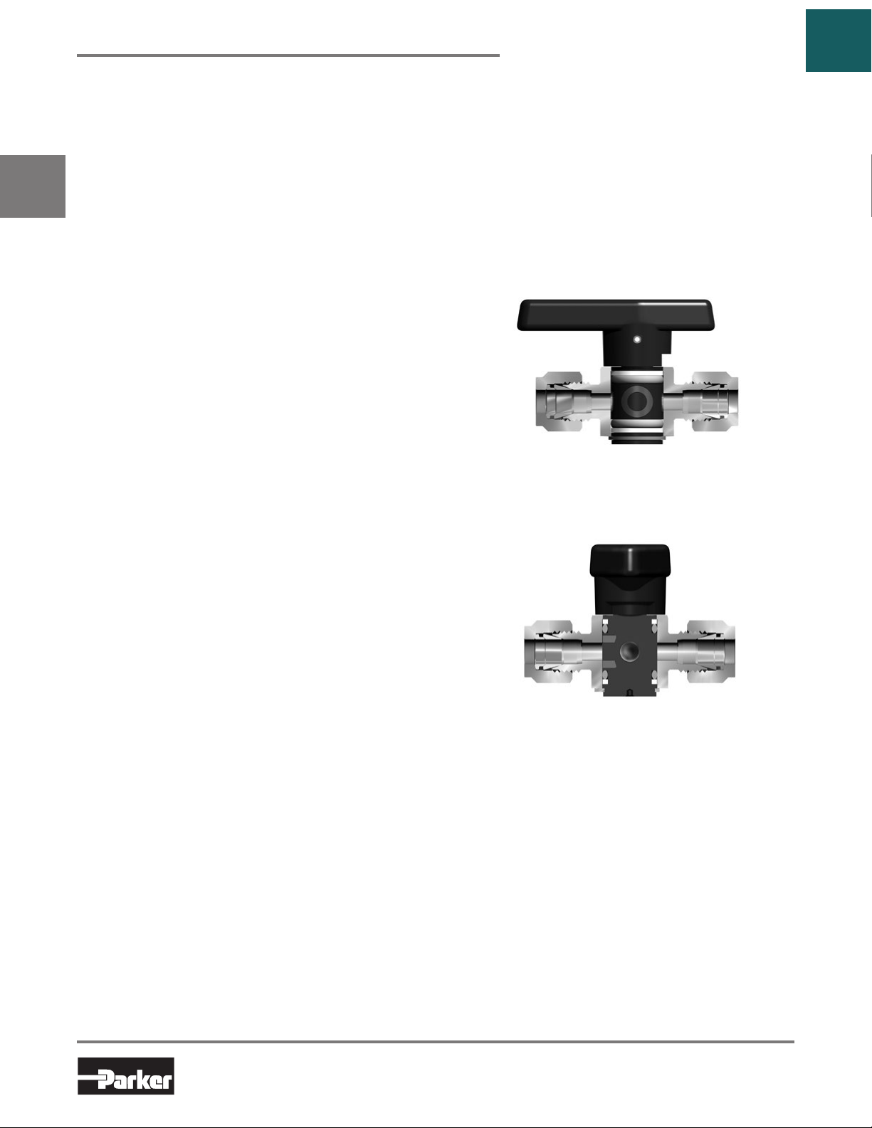
Parker MB Series Ball Valves, with their rugged
compact design, offer positive shut off or directional
control of fluids in process, power and instrumentation
applications. The unique one piece seat/packing
design insures excellent sealing characteristics while
accommo dating a superior temperature range and
cycle life.
These valves are available in two-way and three-way
MB
configurations, brass and stainless steel construction,
with a wide variety of port connections. Also, all ports
are suitable as inlets to full operating pressure of the
valve.
Features
One piece seat/packing design
Broad temperature range
Coated metal inserts
One piece stem/ball
Wide variety of US Customary and SI ports
Panel mountable to 1/4" thickness
Bi-directional flow
Handle indicates direction of flow
Full operating pressure at any port
Positive handle stops
Color coded handles
100% factory tested
Vent option
Manual, electric or pneumatic actuation
Leak-tight center-off position on three-way valves
Specifications
Pressure
Rating
Temperature
Rating
Orificer
C
V
Body
Materials
Body
Configurations
Port
Connections
Port Size
Seat/Packing
* Preset from factory to 1000 psig (69 bar) bubble tight service.
To achieve higher pressures packing nut must be tightened with
Packing Tool MB6X5. Additional details are in INI-243 Installation
Instructions. Packing in vented MB Series Ball Valves is factory
adjusted for the maximum valve pressure rating of 500 psig (34
bar).
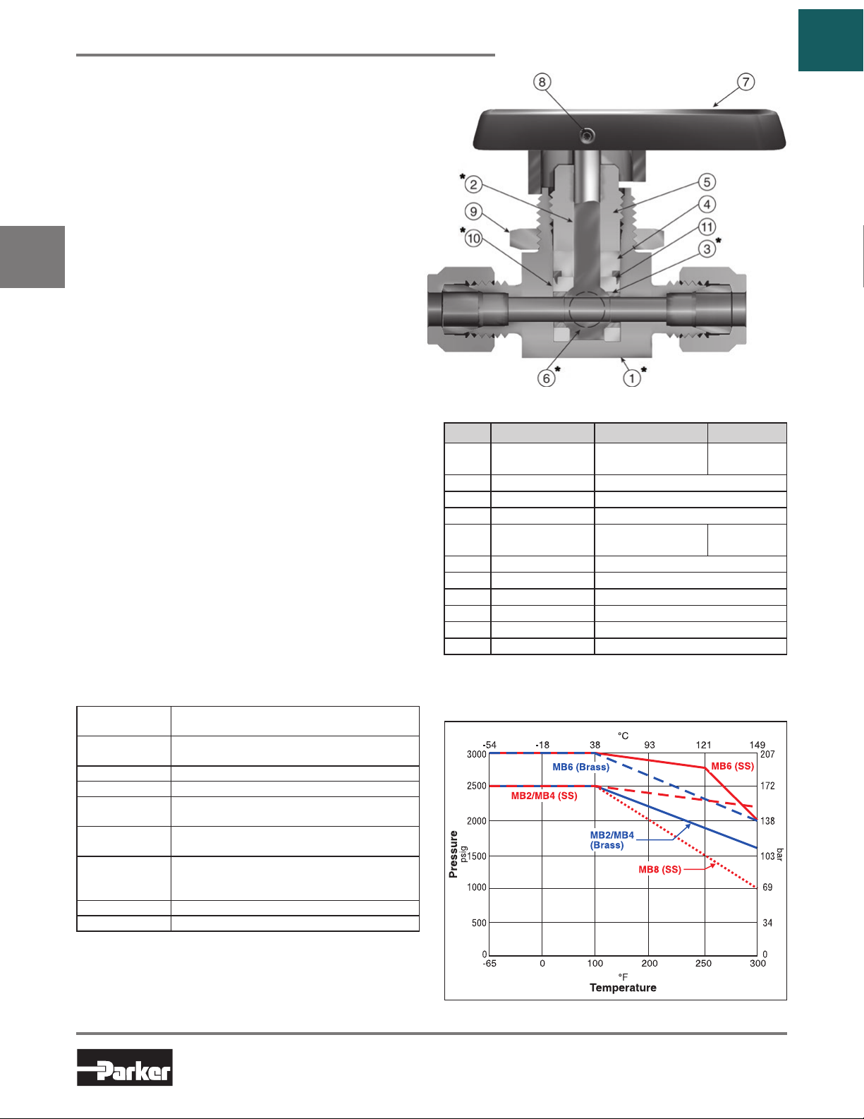
3000 psig* (207 bar) CWP - MB6
2500 psig* (172 bar) CWP - MB2/MB4/MB8
-65°F to 300°F
(-54°C to 149°C)
.052" to .406" (1.3mm to 10.3mm)
.05 to 6.96
Stainless steel and brass
two-way (in-line and angle)
3-way, 4-way and 5-way
Tube compression (CPI™ / A-LOK
NPT (Male / Female)
BSP, VacuSeal and UltraSeal
1/16" to 3/4" and 3mm to 12mm
PFA-Perfluoroalkoxy
Catalog 4121-BV
Go to
Table of
Contents
Materials of Construction
Item # Part Description Stainless Steel Brass
1 Body
2 Stem ASTM A 276 Type 316
3 Hollow Insert 316 Stainless Steel
4 Packing Washer ASTM B 16 Alloy C36000
5 Packing Nut
6 Solid Insert 316 Stainless Steel
7 Handle Nylon 6/6
8 Set Screw Stainless Steel
9 Panel Nut 316 Stainless Steel**
*10 Seat/Packing Perfluoroalkoxy (PFA)
11 Packing Ring ASTM A 479 Type 316
* Wetted Parts **Nickel Plated Brass for MB8
Lubrication: Perfluorinated polyether
ASTM A 276
Type 316
ASTM A 479
Type 316
ASTM B 16
Alloy C36000
ASTM B 16
Alloy C36000
Pressure vs. Temperature
®
)
Note: To determine MPa, multiply bar by 0.1
16
Parker Hannifin Corporation
Instrumentation Products Division
Jacksonville, AL USA
http://www.parker.com/ipdus
Page 19

Catalog 4121-BV
H-Maximum Panel Thickness
I-Panel Hole Diameter
J-Body Width
Port
Two-Way In-Line MB Series Ball Valves
Two-Way In-Line Dimensions, Flow Data
Go to
Table of
Contents
G
F
Two-Way In-Line
Vented – In off position
the downstream port
vents to atmosphere
E
through a hole in the
side of the body.
D
2
K
B
Model shown: 4A-MB6LPFA-SSP
Port
Basic
Size
Part #
1Z
1A 1/16" A-LOK
2Z
2A 1/8" A-LOK
M3Z
M3A 3mm A-LOK
2F
4Z 1/4" CPI™
4A 1/4" A-LOK
M6Z 6mm CPI™
M6A 6mm A-LOK
2Z
2A 1/8" A-LOK
2F
4M 1/4" Male NPT
4Z 1/4" CPI™
4A 1/4" A-LOK
4F 1/4" Female NPT
4M4Z 1/4" Male NPT
4M4A 1/4" Male NPT
4V 1/4" VacuSeal
6Z 3/8" CPI™ 1.31 1.31
6A 3/8" A-LOK
M6Z 6mm CPI™ 1.19 1.19
M6A 6mm A-LOK
M8Z 8mm CPI™ 1.22 1.22
M8A 8mm A-LOK
8A
8Z 1/2" A-CPI™
8F 0.406 10.3 6.1 0.20 1/2" FNPT
12A
12Z 3/4" CPI
M12A
M12Z 12mm CPI™
* Tested in accordance with ISA S75.02. Gas flow will be choked when P1 - P
™
† For CPI
and A-LOK®, dimensions are measured with nuts in the finger tight position.
0.052 1.3 0.03 0.46
0.093 2.4 0.20 0.42
MB2L
0.086 2.2 0.17 0.43
MB4L 0.125 3.2 0.44 0.34
0.093 2.4 0.18 0.55
MB6L
0.187 4.7 1.02 0.53
0.406 10.3 10.7 0.16
MB8L
0.406 10.3 6.4 0.19
0.375 9.5 10.7 0.16
Flow Data
Cv X
*Inch mm Port 1 Port 2 A† B† D E F G H I J K
T
End Connections
1/16" CPI™
®
1/8" CPI™
®
3mm CPI™
®
1/8" Female NPT
®
®
1/8" CPI™
®
(27.7)
1/8" Female NPT
®
(30.2)
1/4" CPI™
1/4" A-LOK
®
(33.3) (33.3)
®
(30.2) (30.2)
®
(31.0) (31.0)
®
1/2" A-LOK
®
3/4" A-LOK
™
12mm A-LOK
®
/ P1 = xT .
2
0.84
(21.3)
1.00
(25.4)
1.00
(25.4)
0.81
(20.6)
1.12
(28.5)
1.12
(28.5)
1.09
(27.7)
1.00
(25.4)
1.00
(25.4)
1.19
(30.2)
1.03
(26.2)
1.00
®
(25.4)
1.03
(26.2)
1.94
(49.3)
1.56
(39.6)
1.94
(49.3)
1.96
(49.8)
H - Maximum Panel Thickness
I - Panel Hole Diameter
J - Body Width
VENTED STANDARD
ON
Port 1
OFF
A
Dimensions
Inches (mm)Orifice
0.84
(21.3)
1.00
0.34
1.31
1.88
0.75
0.25
0.58
(25.4)
1.00
(25.4)
0.81
(20.6)
1.12
(28.5)
1.12
(28.5)
1.09
1.00
(25.4)
1.00
(25.4)
1.19
1.03
(26.2)
1.19
(30.2)
1.03
(26.2)
1.94
(49.3)
1.56
(39.6)
1.94
(49.3)
1.96
(49.8)
(8.6)
0.34
(8.6)
0.44
(11.2)
0.69
(17.5)
(33.3)
1.31
(33.3)
1.56
(39.6)
2.39
(60.7)
(47.8)
1.88
(47.8)
2.37
(60.2)
4.50
(114.3)
(19.1)
(6.4)
0.75
0.25
(19.1)
(6.4)
0.88
0.25
(22.4)
(6.4)
1.50
0.38
(38.1)
(9.7)
Dimensions in inches/millimeters are
for reference only, subject to change.
(14.7)
0.58
(14.7)
0.77
(19.6)
1.50
(38.1)
0.58
(14.7)
0.58
(14.7)
0.80
(20.3)
1.50
(38.1)
(7.1)
(7.1)
(9.7)
(17.5)
MB
0.28
0.28
0.38
0.69
17
Parker Hannifin Corporation
Instrumentation Products Division
Jacksonville, AL USA
http://www.parker.com/ipdus
Page 20

Two-Way Angle / Three-Way MB Series Ball Valves
Port 1
Two-Way Angle and Three-Way Dimensions, Flow Data
Catalog 4121-BV
Go to
Table of
Contents
Two-Way Angle
G
MB
Port 2
C
B
Model shown:
F
D
VENTED STANDARD
ON
OFF
E
E
D
Port 2
4A-MB6APFA-SSP
Port
Basic
Size
Part #
1Z
1A 1/16" A-LOK
2Z
MB2A
MB2X
2A 1/8" A-LOK
M3Z
M3A 3mm A-LOK
2F
4Z 1/4" CPI™
MB4A
MB4X
4A 1/4" A-LOK
M6Z 6mm CPI™
M6A 6mm A-LOK
4Z
4A 1/4" A-LOK
4F 1/4" Female NPT
4V 1/4" VacuSeal
4Z4Z4M
MB6A
MB6X
4A4A4M 1/4" A-LOK
6Z 3/8" CPI™
6A 3/8" A-LOK
M6Z 6mm CPI™
M6A 6mm A-LOK
M8Z 8mm CPI™
M8A 8mm A-LOK
8A
8Z 1/2" A-CPI™
8F 0.406 10.3 5.0 0.33 1/2 “ Female NPT
MB8A
MB8X
12A
12Z 3/4" CPI™
M12A
M12Z 12mm CPI™
Flow Data
Cv X
0.052 1.3 0.02 0.58
0.093 2.4 0.18 0.48
0.086 2.2 0.15 0.47
0.125 3.2 0.34 0.45
0.187 4.7 0.70 0.58
0.406 10.3 5.4 0.36
0.406 10.3 4.9 0.39
0.375 9.5 5.6 0.37
*Inch mm Port 1 Port 2 Port 3 ‡ A† B† C C E F G H I J
T
1/4" CPI™ 1/4" CPI™ 1/4" Male NPT
* Tested in accordance with ISA S75.02. Gas flow will be choked when P1 - P2 / P1 = xT .
‡ Not applicable for the two-way Angle pattern.
† For CPI™ and A-LOK®, dimensions are measured with nuts in the finger tight position.
End Connections
1/16" CPI™
®
1/8" CPI™
®
3mm CPI™
®
1/8" Female NPT
®
®
1/4" CPI™ 1.19 1.19 1.15
®
(30.2) (30.2) (29.2)
®
1/4" A-LOK® 1/4" Male NPT
®
®
®
®
1/2" A-LOK
®
3/4" A-LOK
12mm A-LOK
®
Three-Way
G
Port 3
B
F
A
Model shown:
4A-MB6XPFA-SSP
0.84
0.84
(21.3)
1.00
(25.4)
1.00
(25.4)
0.81
(20.6)
1.12
(28.4)
1.12
(28.4)
1.19
(30.2)
1.31
(33.3)
1.19
(30.2)
1.22
(31.0)
1.75
(44.5)
1.56
(39.6)
1.75
(44.5)
1.75
(44.5)
0.81
(20.6)
0.97
(24.6)
0.97
(24.6)
0.81
(20.6)
1.12
(28.4)
1.12
(28.4)
1.03
(26.2)
1.23
(31.2)
1.15
(29.2)
1.18
(30.0)
1.75
(44.5)
1.56
(39.6)
1.75
(44.5)
1.75
(44.5)
(11.2)
(17.5)
(21.3)
1.00
(25.4)
1.00
(25.4)
0.81
(20.6)
1.12
(28.4)
1.12
(28.4)
1.03 1.03 1.03
(26.2) (26.2) (26.2)
1.03 1.03 1.03
(26.2) (26.2) (26.2)
1.19
(30.2)
1.31
(33.3)
1.19
(30.2)
1.22
(31.0)
1.75
(44.5)
1.56
(39.6)
1.75
(44.5)
1.75
(44.5)
H - Maximum Panel
Thickness
I - Panel Hole
Diameter
J - Body Width
VENTED STANDARD
Port 1
C
Dimensions
Inches (mm)Orifice
0.34
1.31
(33.3)
(33.3)
1.56
(39.6)
2.39
(60.7)
1.88
(47.8)
(47.8)
2.37
(60.2)
4.50
(114.3)
(19.1)
(19.1)
(22.4)
(38.1)
(8.6)
0.34 1.31 1.88 0.75 0.25 0.58 0.58
(8.6)
0.44
0.69
Dimensions in inches/millimeters are
for reference only, subject to change.
0.75
0.88
1.50
ON
CENTER
OFF
ON
0.25
(6.4)
(6.4)
0.25
(6.4)
0.38
(9.7)
0.58
(14.7)
(14.7)
0.77
(19.6)
1.50
(38.1)
0.58
(14.7)
(14.7)
0.80
(20.3)
1.50
(38.1)
18
Parker Hannifin Corporation
Instrumentation Products Division
Jacksonville, AL USA
http://www.parker.com/ipdus
Page 21

Catalog 4121-BV
MB Series Ball Valves
How to Order Two-Way In-Line, Two-Way Angle and Three-Way Patterns
The correct part number is easily derived from the following example and ordering chart. The six product
characteristics required are coded as shown in the chart.
The following example describes a MB Series, two-way, in-line pattern ball valve with 1/8" CPI™ compression end
connections for ports 1 and 2 Inline
Go to
Table of
Contents
Example:
2Z – MB2LPFA – SSP
– –
Port
1*
1Z
1/16" CPI™
1A 1/16" A-LOK®
2Z 1/8" CPI™
2A 1/8" A-LOK
2F 1/8" Female NPT
4Z 1/4" CPI™
4A 1/4" A-LOK
1/8" CPI™
2Z
2A 1/8" A-LOK®
2F 1/8" Female NPT
4Z 1/4" CPI™
4A 1/4" A-LOK
4F 1/4" Female NPT
4M 1/4" Male NPT
4V 1/4" VacuSeal
1/2" CPI™
8Z
8A 1/2" A-LOK
8F 1/2" Female NPT
* Valves with identical port connections for port 1 and port 2 require only one designator.
Port
2*
Ports
1, 2 and 3*
®
®
®
®
Port
3*
M3Z 3mm CPI™
M3A 3mm A-LOK
M6Z 6mm CPI™
M6A 6mm A-LOK®
6Z 3/8" CPI™
6A 3/8" A-LOK®
M6Z 6mm CPI™
M6A 6mm A-LOK®
M8Z 8mm CPI™
M8A 8mm A-LOK
12Z 3/4" CPI™
12A 3/4" A-LOK
M12Z 12mm CPI™
M12A 12mm A-LOK
®
®
®
Valve
Series
Valve
Series
MB2L
MB2A
MB2X
MB4L
MB4A
MB4X
MB6L
MB6A
MB6X
MB8A
MB8L
MB8X
®
Seat
Material
Seat
Material
PFA
Perfluoro
alkoxy
Body
Material
Body
Material
SSP Stainless Steel
(Stainless
Steel with
Stainless Steel
Panel Nut)
BP Brass (Brass
with Stainless
Steel Panel
Nut) (Only
available in
MB 2, 4, 6)
Lock-Out Device Option
MB
Oval Handle Option
Pneumatic Actuator
Option
How to Order Options (Two-Way, Angle, and Three-Way)
Lock-Out Devices – Add the suffix -LD to the end of the part number to order directly on the valve.
For field installation, simply substitute the correct valve series number in the following nomenclature: LD-valve series. Example: LD-MB6L
Colored Handles – Add the designator corresponding to the correct handle as a suffix to the part number:
R - red, Y - yellow. Example: 4Z-MB6LPFA-SSP-G
NOTE: Not offered in MB8 series.
Stainless Steel Handles – Add the suffix -ST to the part number.
Oval Handles – Add the suffix -S to the part number.
-S-color designator. Example: 6Z-MB6APFA-SSP-S-W
NOTE: MB6 series only.
Vented Valves – Add the designator V after the MB in the part number for the vent option.
Example: 2Z-MBV2XPFA-SSP.
Example: 6Z-MB6APFA-SSP-S. If requesting a colored oval handle, add the suffix
Example: 4F-MB6LPFA-SSP-ST (MB6 series only)
Example: 2F-MB4LPFA-SSP-LD.
W - white, B - blue, G - green,
Oxygen Cleaning – Add the suffix -C3 to the end of the part number to receive valves cleaned and assembled for oxygen service in
accordance with Parker Specification ES8003. Example: 4A-MB4LPFA-SSP-C3
Pneumatic Actuators – For detailed actuator information, refer to the Pneumatic Actuators section of this catalog. For factory assembly,
add the actuator part number as the suffix to the valve part number. Example: 4A-MB4LPFA-SSP-61AC-2. For field installation, specify the
actuator desired. Example: 61AC-2. The appropriate mounting hardware may be obtained by adding the valve series and actuator size to the
prefix MK-. Example: MK-MB4L-61
Electric Actuators – For detailed actuator information, refer to the Electric Actuators section of this catalog. For factory assembly, add the
actuator part number as the suffix to the valve part number. Example: M6A-MB6XPFA-SSP-71C. For field installation, specify the actuator
desired. Example: 71C. The appropriate mounting hardware may be obtained by adding the valve series and actuator series to the prefix MK-.
Example: MK-MB6X-70
19
Parker Hannifin Corporation
Instrumentation Products Division
Jacksonville, AL USA
http://www.parker.com/ipdus
Page 22

Four-Way and Five-Way MB Series Ball Valves
kness
kness
Dimensions, Flow Data
Catalog 4121-BV
Go to
Table of
Contents
Four-Way
G
MB
E
B
Port
Basic
Size
Part #
2A7
2Z7 1/8" Female CPI™
MB6X4 0.063 1.6 0.17 0.16
2F 1/8" Female NPT
2A7
2Z7 1/8" Inverted CPI™
MB6X5 0.063 1.6 0.17 0.16
2F 1/8" Female NPT
* Tested in accordance with ISA S75.02. Gas flow will be choked when P1 - P2 / P1 = xT .
† For CPI™ and A-LOK®, dimensions are measured with nuts in the finger tight position.
F
H - Maximum Panel Thic
I - Panel Hole Diameter
2
1
3
D
4
K
A
Flow Data
Cv XT*Inch mm Port 1 Port 2 A† B† D E F G H I K L
2
1
4
End Connections
1/8" Female A-LOK
1/8" Inverted A-LOK
3
®
®
0.97
(24.6)
0.78
(19.8)
0.97
(24.6)
0.78
(19.8)
Five-Way
G
E
L
B
0.97
(24.6)
0.44
1.57
(11.2)
0.44
(11.2)
(39.9)
1.57
(39.9)
0.78
(19.8)
0.97
(24.6)
0.78
(19.8)
F
A
Dimensions
Inches (mm)Orifice
2.37
(60.2)
2.37
(60.2)
H - Maximum Panel Thic
I - Panel Hole Diameter
D
K
0.88
0.25
0.77
(22.4)
(6.4)
0.88
0.25
(22.4)
(6.4)
Dimensions in inches/millimeters are
for reference only, subject to change.
(19.6)
0.77
(19.6)
0.44
(11.2)
0.44
(11.2)
0.97
(24.6)
0.88
(22.4)
How to Order Four-Way and Five-Way Patterns
The correct part number is easily derived from the following example and ordering chart. The four product
characteristics required are coded as shown in the chart.
The following example describes a MB-Series four-way pattern ball valve with 1/8" female CPI™ compression end
connections for all ports, PFA seat and packing, stainless steel body construction, and a panel mounting nut.
Example:
2Z7 – MB6X4PFA – SSP
– –
End
Connection
End Connection Valve Series Seat Material Body Material
2F
1/8" Female NPT
2Z7 1/8" CPI™
2A7 1/8" A-LOK
®
How to Order Options
Valve
Series
MB6X4
MB6X5
Colored Handles – Add the designator corresponding to the correct handle as a suffix to the part number:
R - red, Y - yellow. Example: 2F-MB6X4PFA-SSP-R
Stainless Steel Handles – Add the suffix -ST to the part number.
Seat
Material
PFA
Perfluoroalkoxy SSP Stainless Steel (Stainless Steel
with Stainless Steel Panel Nut)
Example: 2A7-MB6XPFA-SSP-ST
Body
Material
20
W - white, B - blue, G - green,
Parker Hannifin Corporation
Instrumentation Products Division
Jacksonville, AL USA
http://www.parker.com/ipdus
Page 23

Catalog 4121-BV
Notes
Go to
Table of
Contents
MB
21
Parker Hannifin Corporation
Instrumentation Products Division
Jacksonville, AL USA
http://www.parker.com/ipdus
Page 24

HB Series Ball Valves
Catalog 4121-BV
Introduction
Parker High Pressure HB4 Series Ball Valves provide reliable shut-off or switching functions. The upper and lower
trunnion bearings enhance the resistance of the trunnions against seizure, and increase the valve life in extreme
applications. The compact and rugged design employs spring-loaded seats for high cycle life and low operating
torques at pressures up to 10,000 psig (689 bar).
Go to
Table of
Contents
Features
PEEK trunnion bearings for longer cycle life
Two-way and three-way designs
Compact FNPT version for tight work areas
Blow-out resistant two-piece ball/stem
Full operating pressure at any port
HB
Low operating torque
Manual, electric or pneumatic actuation
Panel mountable to 3/8" (9.6mm) thickness
No packing to adjust
Color coded fracture resistant handles
Handle indicates direction of flow
Positive handle stops
Wide variety of US customary and SI ports
Top of stem marked to indicate flow direction
100% factory tested
Compact package
Heat code traceability
Specifications
Pressure
Rating
Temp. Rating
Body Materials
Body Config.
Port
Connections
Port Size
10,000 psig (689 bar) CWP with PEEK
(PKR) Seats
6,000 psig (414 bar) CWP with PCTFE (K)
Seats
-65˚F to 400˚F (-54˚C to 204˚C)
Stainless steel
Two-way and three-way
Tube compression (CPI™/A-LOK
Short and long female NPT
1/8" – 1/2" (6 mm to 12 mm)
Flow Data
Two-Way HB4L Three-Way HB4X
C
v
X
T
Orifice
Tested in accordance with ISA S75.02. Gas flow will be
choked when P1 - P2 / P1 = xT .
1.02 0.62
0.42 0.71
0.188"
(4.8mm)
(4.8mm)
0.188"
®
)
Two-Way HB4L Design
22
Three-Way HB4X Design
Parker Hannifin Corporation
Instrumentation Products Division
Jacksonville, AL USA
http://www.parker.com/ipdus
Page 25

Catalog 4121-BV
Pressure vs. Temperature
HB Series Ball Valves
Note: To determine MPa, multiply bar by 0.1
This pressure versus temperature chart reflects the
maximum temperature range of indicated materials.
When combining seat and seal materials, the most
restrictive temperature rating of the seats or seals
becomes the limiting factor on valve temperature
range.
Temperature Ratings:
Nitrile (Nitrile) Rubber 40°F to 250°F
(-40°C to 121°C)
Ethylene Propylene Rubber -65°F to 300°F
(-54°C to 149°C)
Fluorocarbon Rubber
-15°F to 400°F
(-26°C to 204°C)
Go to
Table of
Contents
HB
Flow Calculations,
Two-Way HB4L
Inlet
Pressure
psig bar psig bar gpm m3/hr scfm m3/hr
100 7
1000 69
3000 207
6000 414
10000 689
Pressure Drop
∆P
1 0.1 1.0 0.2 10.8 17.4
10 0.7 3.2 0.7 32.0 50.7
50 3.5 7.2 1.6 50.5 76.0
10 0.7 3.2 0.7 101.3 171.3
100 6.9 10.2 2.3 297.7 502.3
500 34.5 22.8 5.2 446.7 749.6
100 6.9 10.2 2.3 542.0 919.9
1000 69.0 32.3 7.3 1297.0 2198.9
1500 103.4 39.5 9.0 1327.2 2248.8
1000 69.0 32.3 7.3 2158.5 3662.7
2000 137.9 45.6 10.4 2188.5 4388.6
3000 206.8 55.9 12.7 2647.9 4486.8
1000 69.0 32.3 7.3 2954.3 5020.2
2000 137.9 45.6 10.4 3818.4 6487.0
3000 206.8 55.9 12.7 4236.2 7194.9
Water
@ 60°F (16°C)
Air
@ 60°F (16°C)
Flow Calculations,
Three-way HB4X
Inlet
Pressure
psig bar psig bar gpm m3/hr scfm m3/hr
100 7
1000 69
3000 207
6000 414
10000 689
Pressure Drop
∆P
1 0.1 0.6 0.1 6.6 10.6
10 0.7 2.0 0.4 20.0 31.9
50 3.5 4.4 1.0 37.1 57.4
10 0.7 2.0 0.4 61.8 104.4
100 6.9 6.2 1.4 187.2 316.1
500 34.5 13.9 3.1 337.4 567.7
100 6.9 6.2 1.4 333.1 565.4
1000 69.0 19.6 4.5 903.4 1532.8
1500 103.4 24.0 5.5 1004.4 1703.2
1000 69.0 19.6 4.5 1393.5 2365.2
2000 137.9 27.7 6.3 1803.8 3060.4
3000 206.8 34.0 7.7 2004.9 3399.8
1000 69.0 19.6 4.5 1858.9 3159.0
2000 137.9 27.7 6.3 2499.6 4247.2
3000 206.8 34.0 7.7 2903.0 4932.1
Water
@ 60°F (16°C)
Air
@ 60°F (16°C)
23
Parker Hannifin Corporation
Instrumentation Products Division
Jacksonville, AL USA
http://www.parker.com/ipdus
Page 26

HB Series Ball Valves
.51
(12.9)
2.50
(63.5)
1.00
(25.4)
2.91
(73.9)
A
B
Port 3
Directional indication
provided for panel
mounting when handle
is removed from valve.
Located on top of stem.
1/4˝ Female NPT Port
Port 2
(Port 1‡)
0.38˝ (9.6) – Maximum
Panel Thickness
29/32˝ (23.0) – Panel
Hole Diameter
Port 1
(Port 2‡)
1.06
(26.9)
Dimensions, Pressure Data
HB
( ) Denotes dimensions
in millimeters.
‡ For two-way valves,
Port 1 is the inlet
port and Port 2 is the
outlet port.
Catalog 4121-BV
Model shown:
4F-HB4XPKR-SSP
Go to
Table of
Contents
Basic
Part Number*
2F-HB4
4F-HB4** 1/4" Female NPT 1.47 37.3 1.47 37.3
4FL-HB4 1/4" Female NPT (Long) 1.97 50.0 1.97 50.0
4A-HB4 1/4" A-LOK
4Z-HB4 1/4" CPI™ Compression 2.07 52.6 2.07 52.6
M6A-HB4 6 mm A-LOK
M6Z-HB4 6 mm CPI™ Compression 2.07 52.6 2.07 52.6
6A-HB4
6Z-HB4 3/8" CPI™ Compression 2.19 55.6 2.19 55.6
8A-HB4
8Z-HB4 1/2" CPI™ Compression 2.30 58.4 2.30 58.4
M8A-HB4
M8Z-HB4 8 mm CPI™ Compression 2.07 52.6 2.07 52.6
M10A-HB4
M10Z-HB4 10 mm CPI™ Compression 2.19 55.6 2.19 55.6
M12A-HB4
M12Z-HB4 12 mm CPI™ Compression 2.30 58.4 2.30 58.4
* Flow configurations are two-way (HB4L) and three-way (HB4X); Seat materials are PEEK
(Polyetheretherketone) and PCTFE (Polychlorotrifluoroethylene).
** Designed with shorter end-to-end dimensions than the 4FL model to save space.
† Reduced pressure rating is determined by the maximum rated pressure of the tubing as stated in the Parker Instrument Tubing Selection
Guide Bulletin 4200-TS. The working pressure ratings are limited by the seat material (PCTFE – 6,000 psig (414 bar) maximum and PEEK
– 10,000 psig (689 bar) maximum) and the temperature of the application.
†† For CPI™ and A-LOK® , dimensions are measured with nuts in the finger tight position.
Pressure Rating
@100°F (38°C) End Connection
A‡ B‡
Dimensions
psig bar Port 1 Port 2 inch mm inch mm
1/8" Female NPT 1.47 37.3 1.47 37.3
10,000 689
6,600† 455
6,300† 434
7,975† 550
6,525† 450
6,162† 425
3/8" A-LOK
1/2" A-LOK
8 mm A-LOK
10 mm A-LOK
12 mm A-LOK
®
Compression 2.07 52.6 2.07 52.6
®
Compression 2.07 52.6 2.07 52.6
®
Compression 2.19 55.6 2.19 55.6
®
Compression 2.30 58.4 2.30 58.4
®
Compression 2.07 52.6 2.07 52.6
®
Compression 2.19 55.6 2.19 55.6
®
Compression 2.30 58.4 2.30 58.4
Dimensions in inches/millimeters are
for reference only, subject to change.
24
Parker Hannifin Corporation
Instrumentation Products Division
Jacksonville, AL USA
http://www.parker.com/ipdus
Page 27

Catalog 4121-BV
Materials of Construction
HB Series Ball Valves
Go to
Table of
Contents
HB
No. Part Description 6,000 psi (414 bar) 10,000 psi (689 bar)
1 Handle/insert Nylon 6/6/316 SS Nylon 6/6/316 SS
2 Handle screw Stainless steel Stainless steel
3 Panel nut 316 Stainless steel 316 Stainless steel
4* Stem ASTM A 479 Type 316 ASTM A 479 Type 316
5* Ball trunnion ASTM A 479 Type 316 ASTM A 479 Type 316
6* Port end connector ASTM A 479 Type 316 ASTM A 479 Type 316
7* Spring washer ASTM A 479 Type 316 ASTM A 479 Type 316
8* Seat PCTFE PEEK
9* Seat retainer ASTM A 276 Type 316 ASTM A 276 Type 316
10 Handle stop pins 302 Stainless steel 302 Stainless steel
11 Stem washer PEEK PEEK
12 Stem O-ring back-up PTFE PTFE
13* Stem O-ring Fluorocarbon rubber** Fluorocarbon rubber**
14* Connector end seal PEEK PEEK
15* Spring ASTM A 313 Type 631 ASTM A 313 Type 631
16* Seat retainer O-ring back-up PTFE PTFE
17* Seat retainer O-ring Fluorocarbon rubber** Fluorocarbon rubber**
18* Valve body ASTM A 276 Type 316 ASTM A 276 Type 316
19* Pipe plug (Not shown/HB4L only) 316 Stainless steel 316 Stainless steel
20* Trunnion bearing PEEK PEEK
* Wetted parts
** Optional elastomer seals available
Lubrication: Perfluorinated polyether
25
Parker Hannifin Corporation
Instrumentation Products Division
Jacksonville, AL USA
http://www.parker.com/ipdus
Page 28

HB Series Ball Valves
Catalog 4121-BV
How to Order
The correct part number is easily derived from the following example and ordering chart. The five product
characteristics required are coded as shown in the chart.
Note: If ports 1 and 2 are the same, eliminate the port 2 designator.
Example 1 below describes a HB4X, three-way ball valve with 1/4" CPI™ compression end connections for ports
1 and 2, PEEK seats and fluorocarbon rubber seals, stainless steel body construction, and a panel mounting nut.
Port 3 is always a 1/4" Female NPT port.
Example 2 below describes a HB4L, two-way ball valve with a 1/4" female NPT port 1 and a 1/4" A-LOK®
compression port 2, PCTFE seats and ethylene propylene rubber seals, stainless steel body construction, and a
panel mounting nut. Note: Port 3 will always have a 1/4" Male NPT plug when ordering a HB4L Series two-way
ball valve.
Example 1: 4Z – HB4XPKR – – SSP
HB
Example 2: 4F4A – HB4LK – EPR – SSP
Go to
Table of
Contents
–––
Port 2*Port 1*
Port 1* Port 2*
2F
1/8" Female NPT
4F 1/4" Female NPT
4FL 1/4" Female NPT (Long)
4A 1/4" A-LOK® Compression
4Z 1/4" CPI™ Compression
4MP7 1/4" MPI™ Compression
6A 3/8" A-LOK® Compression
6Z 3/8" CPI™ Compression
6MP7 3/8" MPI™ Compression
8A 1/2" A-LOK® Compression
8Z 1/2" CPI™ Compression
M6A 6 mm A-LOK® Compression
M6Z 6 mm CPI™ Compression
M8A 8 mm A-LOK® Compression
8 mm CPI™ Compression
M8Z
M10A 10 mm A-LOK® Compression
M10Z 10 mm CPI™ Compression
M12A 12 mm A-LOK® Compression
M12Z 12 mm CPI™ Compression
* If ports 1 and 2 are the same, eliminate the port 2 designator.
2F 1/8" Female NPT
4F 1/4" Female NPT
4FL 1/4" Female NPT (Long)
4A 1/4" A-LOK® Compression
4Z 1/4" CPI™ Compression
4MP7 1/4" MPI™ Compression
6A 3/8" A-LOK® Compression
6Z 3/8" CPI™ Compression
6MP7 3/8" MPI™ Compression
8A 1/2" A-LOK® Compression
8Z 1/2" CPI™ Compression
M6A 6 mm A-LOK® Compression
M6Z 6 mm CPI™ Compression
M8A 8 mm A-LOK® Compression
8 mm CPI™ Compression
M8Z
M10A 10 mm A-LOK® Compression
M10Z 10 mm CPI™ Compression
M12A 12 mm A-LOK® Compression
M12Z 12 mm CPI™ Compression
HB4L 2-way
HB4X 3-way
Valve
Series
Valve
Series
PKR PEEK –
Polyetherether ketone
K PCTFE –
Polychloro trifluoro ethylene
Seat
Material
Seat
Material
Seal
Material
Seal
Material
Blank Fluoro-
carbon
Rubber
BN Nitrile
Rubber
EPR Ethylene
Propylene
Rubber
Body
Material
Body
Material
SSP Stainless
Steel with
Panel Nut
26
Parker Hannifin Corporation
Instrumentation Products Division
Jacksonville, AL USA
http://www.parker.com/ipdus
Page 29

Catalog 4121-BV
Actuator Options
HB Series Ball Valves
Go to
Table of
Contents
Double Acting (61AD)
Pneumatic Actuator
Spring Return
(61AC & AO)
70, 80 & 90 Series
Electric Actuator
Pneumatic Actuator
How to Order Options
Lock-Out Devices – Add the suffix -LD to the end of the part number to order directly on the valve.
Example: 2F-HB4LPKR-BN-SSP-LD
For field installation, simply substitute the correct valve series number after LD. Example: LD-HB4L
Colored Handles – Add the designator corresponding to the correct handle as a suffix to the part number:
W - white B - blue G - green R - red Y - yellow
Example: M6A-HB4XPKR-SSP-G
Oxygen Cleaning – Add the suffix -C3 to the end of the part number to receive valves cleaned and assembled for
oxygen service in accordance with Parker Specification ES8003.
Example: 4A-HB4LPKR-EPR-SSP-C3
Pneumatic Actuators – For detailed actuator information, refer to the Pneumatic Actuators section of this
catalog. For factory assembly, add the actuator part number as the suffix to the valve part number.
Example: 4FL-HB4XK-SSP-61ACX-2
For field installation, specify the actuator desired. Example: 61ACX-2
The appropriate mounting hardware may be obtained by adding the valve series and actuator size to the prefix
MK-. Example: MK-HB4X-61
Electric Actuators – For detailed actuator information, refer to the Electric Actuators section of this catalog. For
factory assembly, add the actuator part number as the suffix to the valve part number.
Example: 6A-HB4XPKR-SSP-71XA
For field installation, specify the actuator desired Example: 71XA
The appropriate mounting hardware may be obtained by adding the valve series and actuator series to the
prefix MK-. Example: MK-HB4X-70
HB
How to Order Maintenance Kits
Handle Kits: HB4-Handle-Color (Example: HB4-HANDLE-RED) – Consists of a red handle and handle screw.
Two-way Seal Kits: KIT-HB4LPKR-SS or KIT-HB4LK-SS – Consists of a two-way trunnion, springs, stem
washers, stem seal, back-up ring, end connector seals, seat springs, seat retainer seals, seat retainer back-up
rings, and seat assemblies.
Three-way Seal Kits: KIT-HB4XPKR-SS or KIT-HB4XK-SS – Consists of a three-way trunnion, springs, stem
washers and stem seal, back-up ring, end connector seals, seat springs, seat retainer seals, seat retainer back-up
rings, and seat assemblies.
27
Parker Hannifin Corporation
Instrumentation Products Division
Jacksonville, AL USA
http://www.parker.com/ipdus
Page 30

MPB Series Ball Valves
Catalog 4121-BV
MPB Series Valves
Parker MPB series manually, pneumatically and electrically actuated two-way and three-way ball valves are
designed for 1/4 and 1/2 turn media shutoff or switching applications up to 20,000 psi. Our trunion style ball
design and spring loaded seats make the MPB series ideal for severe service applications. The end connector
design enables a variety of end connections and combinations for specific customer applications.
Go to
Table of
Contents
MPB
Two Way
.187 Orifice
(Standard)
.375 Orifice
(High Flow)
Ball Valves
Parker
Tubing
Standard
1/8" O.D. 2F-MPBLPK-V-SSP 15,000 1/8" NPT 0.187 0.187 1.45 4.63
1/4" O.D. 4F-MPBLPK-V-SSP 15,000 1/4" NPT 0.187 0.187 1.45 4.63
1/4" O.D. 4MP7-MPBLPK-V-SSP 15,000 1/4" MPI 0.187 0.125 0.45 5.00
3/8" O.D. 6F-MPBLPK-V-SSP 15,000 3/8" NPT 0.187 0.187 1.45 4.65
3/8" O.D. 6MP7-MPBLPK-V-SSP 15,000 3/8" MPI 0.187 0.187 1.45 5.00
1/2" O.D. 8MP7-MPBLPK-V-SSP 15,000 1/2" MPI 0.187 0.187 1.45 5.50
9/16" O.D. 9MP7-MPBLPK-V-SSP 15,000 9/16" MPI 0.187 0.187 1.45 5.50
High Flow (H)
1/2" O.D. 8F-MPBLPKH-V-SSP 15,000 1/2" NPT 0.375 0.375 6.08 5.63
1/2" O.D. 8MP7-MPBLPKH-V-SSP 15,000 1/2" MPI 0.375 0.359 5.82 6.44
9/16" O.D. 9MP7-MPBLPKH-V-SSP 15,000 9/16" MPI 0.375 0.359 5.82 6.44
3/4" O.D. 12MP7-MPBLPKH-V-SSP 15,000 3/4" MPI 0.375 0.375 6.08 6.67
1" O.D. 16MP7-MPBLPKH-V-SSP 12,500 1" MPI 0.375 0.375 6.08 7.45
Ultra High Flow (UH)
3/4" O.D. 12MP7-MPBLPKUH-V-SSP 10,000 3/4" MPI 0.500 0.469 7.60 6.86
1" O.D. 16MP7-MPBLPKUH-V-SSP 10,000 1" MPI 0.500 0.500 8.80 8.48
Part No. PSI Connection
Orifice Minimum Orifice C
.500 Orifice
Two-Way
(UltraHigh Flow)
Inches
v
Dimensions in inches/millimeters are
for reference only, subject to change.
A
28
Parker Hannifin Corporation
Instrumentation Products Division
Jacksonville, AL USA
http://www.parker.com/ipdus
Page 31

Catalog 4121-BV
MPB Series Ball Valves
Three Way
Ball Valves
Diverter
Tubing
Standard
1/8" O.D. 2F-MPBXPKD-V-SSP 2F-MPBXPK-V-SSP 15,000 1/8" NPT 0.187 0.187 0.71 4.63 0.50
1/4" O.D. 4F-MPBXPKD-V-SSP 4F-MPBXPK-V-SSP 15,000 1/4" NPT 0.187 0.187 0.71 4.63 1.06
1/4" O.D. 4MP7-MPBXPKD-V-SSP 4MP7-MPBXPK-V-SSP 15,000 1/4" MPI 0.187 0.125 0.18 5.00 1.18
3/8" O.D. 6F-MPBXPKD-V-SSP 6F-MPBXPK-V-SSP 15,000 3/8" NPT 0.187 0.187 0.71 4.65 1.06
3/8" O.D. 6MP7-MPBXPKD-V-SSP 6MP7-MPBXPK-V-SSP 15,000 3/8" MPI 0.187 0.187 0.71 5.00 1.18
1/2" O.D. 8MP7-MPBXPKD-V-SSP 8MP7-MPBXPK-V-SSP 15,000 182" MPI 0.187 0.187 0.71 5.50 1.44
9/16" O.D. 9MP7-MPBXPKD-V-SSP 9MP7-MPBXPK-V-SSP 15,000 9/16" MPI 0.187 0.187 0.71 5.50 1.44
High Flow (H)
1/2" O.D. 8F-MPBXPKDH-V-SSP 8F-MPBXPKH-V-SSP 15,000 1/2" NPT 0.375 0.375 2.40 5.63 1.06
1/2" O.D. 8MP7-MPBXPKDH-V-SSP 8MP7-MPBXPKH-V-SSP 15,000 1/2" MPI 0.375 0.359 2.30 6.44 1.37
9/16" O.D. 9MP7-MPBXPKDH-V-SSP 9MP7-MPBXPKH-V-SSP 15,000 9/16" MPI 0.375 0.359 2.30 6.44 1.37
3/4" O.D. 12MP7-MPBXPKDH-V-SSP 12MP7-MPBXPKH-V-SSP 15,000 3/4" MPI 0.375 0.375 2.40 6.67 1.18
1" O.D. 16MP7-MPBXPKDH-V-SSP 16MP7-MPBXPKH-V-SSP 15,000
Ultra High Flow (UH)
3/4" O.D. 12MP7-MPBXPKDUH-V-SSP 12MP7-MPBXPKUH-V-SSP 10,000 3/4" MPI 0.500 0.469 3.20 6.86 1.37
1" O.D. 16MP7-MPBXPKDUH-V-SSP 16MP7-MPBXPKUH-V-SSP 10,000 1" MPI 0.500 0.500 3.80 8.48 2.18
Locking Devices – Add suffix “-LD” to the end of the part number.
Example: 9MP7-MPBLPKH-V-SS-LD
3-Way 90°
.187 Orifice
(Standard)
SSelector
3-Way 180° PSI Connection
1" MPI 0.375 0.375 2.40 7.45 1.99
.500 Orifice
Three-Way
.375 Orifice
(High Flow)
Minimum
Orifice
Orifice C
Dimensions in inches/millimeters are
for reference only, subject to change.
Inches
v
A B
Go to
Table of
Contents
MPB
29
Parker Hannifin Corporation
Instrumentation Products Division
Jacksonville, AL USA
http://www.parker.com/ipdus
Page 32

MPB Series Ball Valves
Materials of Construction
Catalog 4121-BV
Go to
Table of
Contents
MPB
19
11
4
1
2
3
5
7
8
13
6
7
17
12
7
9
10
15
18
14
20
16
Item # Description Material
1 Handle 300 SER. SS
2 Set Screw 17-4PH-H900
3 Stop Collar, 180 Degree 300 SER. SS
4 Stem 17-4PH-H900
5 Panel Nut 300 SER. SS
6 Bearing Washer Peek/30% Glass
7 O-ring Fluorocarbon Rubber
8 Back Up Ring PTFE
9 Ball Seat Assembly 316SS/Arlon
10 Belleville Washer 302SS
11 Packing Washer 316SS
12 Back Up Washer PTFE
13 Body Bushing Ampco 45
14 Trunion, 180 Degree 316SS
15 Bottom Bushing Ampco 45
16 Body 316SS
17 O-ring Fluorocarbon Rubber
18 O-ring Fluorocarbon Rubber
19 Seat Gland 316SS
20 Bottom Gland 316SS
30
Parker Hannifin Corporation
Instrumentation Products Division
Jacksonville, AL USA
http://www.parker.com/ipdus
Page 33

Catalog 4121-BV
MPB Series Ball Valves
How to Order MPB Series Valves
The correct part number is easily derived from the following example and ordering chart. The nine product
characteristics required are coded as shown in the chart.
The following example describes an MPB Series, three-way diverter ball valve with a .375" orifice, fluorocarbon
rubber seals, 1/4" MPI medium pressure inverted connections on all ports and the optional lock out device.
Example:
4MP7 – MPBXPKDH – V – SSP – LD
––
–
–
Go to
Table of
Contents
Inlet/Outlet
Connection
Size
Inlet / Outlet
Connection
Size
2 *
4
6
8
9 **
12
16
* Female
Pipe Only
** MP7 and
MF only
1/8"
1/4"
3/8"
1/2"
9/16"
3/4"
1"
Connection
Type
Connection
Type
F
Female
Pipe
MP7 Parker
MPI™
Female
MF
Cone &
Thread
Valve
Series
Valve
Series
MPB
Valve
Type
Valve
Type
L
2-Way
X 3-Way
Seat
Material
Seat
Material
PK
PEEK
Three-Way
Valve Type
Three-Way
Valve Type
Blank
Selector
D Diverter
Orifice
Size
Orifice
Size
Blank
.187"
H .375"
UH .500"
Seal
Material
Packing
Material
V***
Fluorocarbon
Rubber
KZ Highly
Fluorinated
Fluorocarbon
Rubber
BN Nitrile
Rubber
Ethylene
EPR
Propylene
Rubber
*** Standard packing
material
Body
Material
Body
Material
SSP
Stainless
Steel
Options
(See Below)
LD
Lock out Device
SRH Spring Return
Handle
ACT Actuated
How to Order Options
Lock Out Devices – add the suffix -LD to the end of the part number to order factory mounted on the valve.
Options
MPB
Actuated – Contact factory for options.
31
Parker Hannifin Corporation
Instrumentation Products Division
Jacksonville, AL USA
http://www.parker.com/ipdus
Page 34

SWB Series Ball Valves
Introduction
Parker’s three-piece SWB Series Ball Valves are
durable valves that can handle the pressure and
piping loads. The center section can swing out to
quickly and easily replace seats, seals and the
ball without major disruption to the piping system.
Catalog 4121-BV
Go to
Table of
Contents
SWB
Model Shown: 8Z-SWB8L-RT-BN-SS
Features
Ultra low internal volume
Free floating ball design allows for seat wear
compensation
Self-compensating stem seal
Spring-loaded seats
Blow out resistant stem
Fully enclosed body bolting
Four bolt construction
ISO-type actuator mounting design
Pneumatic and electric actuation options
100% factory tested
Specifications
Body Materials
Seat Materials
Seal Materials
Flow Data
Pressure Ratings
Temperature Ratings — Seats
Reinforced PTFE
Seats
PEEK Seats
Temperature Ratings — Seals
Nitrile Rubber
Seals
Ethylene
Propylene
Rubber Seals
Fluorocarbon
Rubber Seals
PTFE Seals
Grafoil® Seals
Stainless Steel
Reinforced PTFE
PEEK
Nitrile Rubber
Ethylene Propylene Rubber
Fluorocarbon Rubber
PTFE
®
Grafoil
: 1.1 to 35.0
C
V
2500 psig (172 bar)
1500 psig (103 bar)
SWB16 with PEEK Seats
-65°F to 450°F (-54°C to 232°C)
-65°F to 600°F (-54°C to 316°C)
-40°F to 250°F (-40°C to 121°C)
-65°F to 300°F (-54°C to 149°C)
-15°F to 400°F (-26°C to 204°C)
-65°F to 350°F (-54°C to 177°C)
-65°F to 600°F (-54°C to 316°C)
32
Parker Hannifin Corporation
Instrumentation Products Division
Jacksonville, AL USA
http://www.parker.com/ipdus
Page 35

Catalog 4121-BV
Materials of Construction
SWB Series Ball Valves
Model Shown:
4Z-SWB4L-RT-V-SS
Go to
Table of
Contents
Materials of Construction
Item
#
1 Body 1 ASTM A 351 Grade CF3M
2 Lower Packing 1 PTFE
3 Upper Packing 1 PTFE
4 Packing Support 2 PEEK
5 Packing Gland 1 ASTM A 276 Type 304
6 Stem Spring 4
7 Stem Hex Nut 2 ASTM A 276 Type 304
8 Grounding Spring 1 ASTM A 276 Type 304
9 Handle Assembly 1 ASTM A 276 Type 304; Vinyl Covered
10 Ball 1 ASTM A 276 Type 316
11 Thrust Washer 2 PEEK
12 Stem 1 ASTM A 276 Type 316
13 Body Seal 2 Fluorocarbon Rubber
14 Seat 2 Reinforced PTFE, PEEK
15 Seat Spring
16 End Flanges 2 ASTM A 351 Grade CF3M
17 Body Bolts 4 ASTM A 193 Grade B8M Class 2
18 Body Bolt Nuts 4 ASTM A 194 Grade 8M
1 Optional Seat and Packing Seal materials are described in the How to Order section.
2 Optional Seal materials are described in the How To Order Section.
3 Size 8 SWB Series Ball Valves only require 3 Stem Springs.
4 PEEK seated SWB Series Ball Valves do not have Seat Springs.
Part Qty Material
3
4
2 ASTM A 666 Type 301
ASTM A 666 Type 301
1
1
2
1
SWB
33
Parker Hannifin Corporation
Instrumentation Products Division
Jacksonville, AL USA
http://www.parker.com/ipdus
Page 36

SWB
SWB Series Ball Valves
Catalog 4121-BV
Pressure vs. Temperature
Note: This Pressure versus Temperature chart reflects the use of indicated seat materials in Stainless Steel
valves without consideration of seal materials. When combining seat and seal materials, the most restrictive
temperature rating of the seats or seals becomes the limiting factor on temperature range. Please refer to page 32
for seal temperature ranges.
Go to
Table of
Contents
Pneumatic Actuated Model Shown:
8Z-SWB8L-RT-V-SS-51AD
34
Electric Actuated Model Shown:
8A-SWB8L-RT-V-SS-71
Parker Hannifin Corporation
Instrumentation Products Division
Jacksonville, AL USA
http://www.parker.com/ipdus
Page 37

Catalog 4121-BV
Dimensions / Flow Data
SWB Series Ball Valves
Go to
Table of
Contents
Flow Data
Basic
Part Number
4Z-SWB4L
4A-SWB4L A-LOK
4F-SWB4L 0.28 7.1 2.9 0.29 Female NPT 1.09 27.7 1.09 27.7
6Z-SWB4L
6A-SWB4L A-LOK
6F-SWB8L 0.44 11.2 8.2 0.35 Female NPT 1.29 32.8 1.29 32.8
8Z-SWB8L
8A-SWB8L A-LOK® Tube
8F-SWB8L 0.44 11.2 8.2 0.26 Female NPT 1.29 32.8 1.29 32.8
8W-SWB8L 0.41 10.4 6.4 0.35 Tube Socket Weld 1.29 32.8 1.29 32.8
8PBW8-SWB8L 0.44 11.2 8.2 0.26
8PSW-SWB12L 0.52 13.2 13.5 0.34 Pipe Socket Weld 1.35 34.3 1.35 34.3
12Z-SWB12L
12A-SWB12L A-LOK
12F-SWB12L 0.56 14.2 14.7 0.28 Female NPT 1.39 35.3 1.39 35.3
12W-SWB12L 0.56 14.2 14.7 0.28 Tube Socket Weld 1.39 35.3 1.39 35.3
12PBW8-SWB12L 0.56 14.2 14.7 0.28
12PSW-SWB16L 0.88 22.4 35.0 0.29 Pipe Socket Weld 1.95 49.5 1.95 49.5
12Z-SWB16L
12A-SWB16L A-LOK
16Z-SWB16L
16A-SWB16L A-LOK
16F-SWB16L 0.88 22.4 35.0 0.29 Female NPT 1.79 45.5 1.79 45.5
16W-SWB16L 0.88
16PBW8-SWB16L 0.88 22.4 35.0 0.29
Orifice
Inch mm Port 1 Port 2 Inch mm Inch mm Inch mm Inch mm Inch mm Inch mm
0.19 4.8 1.1 0.19
0.28 7.1 4.5 0.19
0.41 10.4 6.4 0.35
0.56 14.2 14.7 0.28
0.56 14.2 14.7 0.28
0.88 22.4 35.0 0.29
CVXT*
22.4 35.0 0.29 Tube Socket Weld 1.79 45.5 1.79 45.5
* Tested in accordance with ISA S75.02. Gas flow will be choked when P
† For CPI™ and A-LOK®, dimensions are measured with nuts in the finger tight position.
End
Connections
CPI™ Tube
®
Tube
CPI™ Tube
®
Tube
CPI™ Tube
Pipe Buttweld
(Schedule 80)
CPI™ Tube
®
Tube
Pipe Buttweld
(Schedule 80)
CPI™ Tube
®
Tube
CPI™ Tube
®
Tube
Pipe Buttweld
(Schedule 80)
A† B† C D E F
1.59 40.4 1.59 40.4
1.59 40.4 1.59 40.4
2.03 51.6 2.03 51.6
1.35 34.3 1.35 34.3
2.03 51.6 2.03 51.6
1.37 34.8 1.37 34.8
2.50 63.5 2.50 63.5
2.68 68.1 2.68 68.1
1.81 46.0 1.81 46.0
- P2 / P1 = xT .
1
Dimensions
SWB
0.68 17.3 1.28 32.5 2.00 50.8 3.00 76.2
0.89 22.6 1.54 39.1 2.36 59.9 3.94 100.1
1.06 26.9 1.81 46.0 2.59 65.8 3.94 100.1
1.25 31.8 2.30 58.4 3.00 76.2 5.71 145.0
Dimensions in inches/millimeters are
for reference only, subject to change.
35
Parker Hannifin Corporation
Instrumentation Products Division
Jacksonville, AL USA
http://www.parker.com/ipdus
Page 38

SWB Series Ball Valves
Catalog 4121-BV
How to Order
The correct part number is easily derived from the following example and ordering chart. The four product
characteristics required are coded as shown in the chart.
The example below describes a SWB8L Two-Way Ball Valve with 1/2" A-LOK® end connections for ports 1 and 2,
reinforced PTFE seats, Nitrile rubber body seals, and stainless steel construction.
* Note: If ports 1 and 2 are the same, eliminate the port 2 designator.
Example:
8A – SWB8L – RT – BN – SS
–
–––
Go to
Table of
Contents
SWB
Material
Seat
Material
Seat
1
Seal
Material
Seal
Material
T PTFE
BN Nitrile Rubber
EPR Ethylene
Propylene Rubber
V Fluorocarbon
Rubber
G Grafoil® Gasket
1, 2
Body
Material
Body
Material
SS Stainless
Steel
Port
Size
Port
Size
4
Z
CPI™ Tube
6
A A-LOK® Tube
8
F Female NPT
12
W Tube Socket Weld
16
PSW Pipe Socket Weld
PBW8 Pipe Buttweld (Schedule 80)
1 Not available in size 12.
2 Grafoil® Seals only available with PEEK Seats.
Note: Upper and Lower PTFE packing is replaced with PEEK when valves are ordered with PEEK Seats.
Port 2*Port 1*
Port 1* Port 2*
Valve
Series
Valve
Series
SWB4
SWB8
SWB12
SWB16
Valve
Configuration
Valve
Configuration
L 2-Way PKR Virgin PEEK
RT Glass Reinforced
PTFE
How to Order Options Examples
Lever Lock-Out Devices –
Add the suffix -LD to the end of the part number to order directly on the valve. 4F-SWB8L-RT-V-SS-LD
For field installation, order part number as shown in the example. SWB8/12-HANDLE-LOCKING
Oval Handles – Add the suffix -S to the end of the part number. 8A-SWB8L-RT-T-SS-S
Oval Handle Lock-Out Devices –
Add the suffix -LD to the end of the part number to order directly on the valve. 6F-SWB8L-RT-V-SS-S-LD
For field installation, order part number as shown in the example. SWB8/12-HANDLE-OVAL-LOCKING
Pneumatic Actuators – For detailed actuator information, refer to the
Pneumatic Actuators section of this catalog.
For factory assembly, add the actuator part number as the suffix to the
valve part number. 8F-SWB8L-RT-BN-SS-61AC-2
For field installation, specify the the actuator desired. 61AC-2
The appropriate mounting hardware may be obtained by adding the valve series
and actuator size to the prefix MK-. MK-SWB8L-61
Electric Actuators – For detailed actuator information, refer to the
Electric Actuators section of this catalog.
For factory assembly, add the actuator part number as the suffix to the
valve part number. 8A-SWB8L-RT-EPR-SS-71A
For field installation, specify the actuator desired. 71A
The appropriate mounting hardware may be obtained by adding the valve series
and actuator series to the prefix MK-. MK-SWB8L-70.
Grafoil® is a registered trademark of UCAR Carbon Technology Corporation
36
Parker Hannifin Corporation
Instrumentation Products Division
Jacksonville, AL USA
http://www.parker.com/ipdus
Page 39

Catalog 4121-BV
Notes
Go to
Table of
Contents
SWB
37
Parker Hannifin Corporation
Instrumentation Products Division
Jacksonville, AL USA
http://www.parker.com/ipdus
Page 40

Pneumatic Actuators
Catalog 4121-BV
Introduction
Parker 60 Series spring return (AC/AO) or double acting (AD) rack and pinion actuators are compact, simply
designed devices that are quality engineered to provide high torque outputs and a high cycle, trouble-free life.
A compact, dual opposed rack and pinion design and guide band suspension combine to produce a symmetrically
balanced, center mount actuator. In addition, the actuator has a short powerful stroke, rapid response, and fully
concentric operating load capability which ensures optimum performance.
Go to
Table of
Contents
Pneu
Act
Features
Three point suspension system uses carbon filled
PTFE guide bands for piston alignment and rack
support
Dual opposed piston design uses air pressure on
two pistons to deliver a balanced force to the pinion
gear
Patented balanced piston design results in even
distribution of bearing loads and eliminates piston
tilting
Multiple spring concept permits actuator use at 40
to 120 psig (2.8 to 8.3 bar) air supply requirements
Suitable for use with dry or lubricated air, non-
corrosive gas, or light hydraulic oil
Aluminum alloy body construction with two
component polyurethane coating
Manual override
Specifications
Operating Pressure
90° Models: 40 to 120 psig (2.8 to 8.3 bar) maximum
AC – Normally Closed Spring Return
AD – Double Acting
AO – Normally Open Spring Return
180° Models: 80 psig (5.5 bar) maximum
ACX – Spring Return
ADX – Double Acting
Temperature Range
-4°F to 175°F (-20°C to 79°C)
Optional high and low temperature ranges available
Operation
Actuators are manufactured with an integral air
manifold and internal porting. The air manifold is
designed for direct mounting of solenoid valves. This
eliminates the need for external tubing and simplifies
installation. For applications not requiring a solenoid
valve, the air manifold inlet ports are marked “A” and
“B”. Air inlet port “A” will rotate the actuator counterclockwise. Spring return actuators fail clockwise.
Options
Solenoid valve
Rotary limit switch with valve position indicator
Breather block
Dual mount actuator
38
Model Shown: 4Z-B6LJ-V-SS-61AD
Parker Hannifin Corporation
Instrumentation Products Division
Jacksonville, AL USA
http://www.parker.com/ipdus
Page 41

Catalog 4121-BV
C
2.36
(59.9)
2.36
(59.9)
1.75
(44.5)
1/4" NPT
2 PLACES
UNC 10-24
X.31 DEEP
4 PLACES
0.95
(24.1)
B
D
1.26
(32.0)
A
C
F
E
1.75
(44.5)
1/8" NPT
2 PLACES
UNC 10-24
X.31 DEEP
2 PLACES
1.0
(25.4)
A
B
0.25
(6.4)
0.50
(12.7)
0.83
(21.1)
2.0
(50.2)
Dimensional Data for 61 Model
Pneumatic Actuators
Go to
Table of
Contents
( ) Denotes dimensions in millimeters
61AD 61AC/O 61ADX 61ACX
Dim
Inch mm Inch mm Inch mm Inch mm
A 4.06 103.1 – – 6.10 154.9 – –
B – – 4.65 118.1 – – 8.50 215.9
C1 3.38 85.9 3.38 85.9 3.38 85.9 3.38 85.9
C2 2.36 59.9 2.36 59.9 2.36 59.9 2.36 59.9
C1 – Single Mount, C2 – Dual Mount
Dimensions in inches/millimeters are for reference only, subject to change.
Dimensional Data for 62, 63, 64, 65, 66, 68 and 69 Models
61 Actuator
Pneu
Act
A B C D E F
Single Mount Dual Mount
Model
Inch mm Inch mm
Inch mm Inch mm Inch mmInch mm Inch mm
62AD 6.26 159.0 – – 4.17 105.9 3.15 80.0 1.26 32.0 2.91 73.9 3.15 80.0
62AC/O – – 6.77 172.0 4.17 105.9 3.15 80.0 1.26 32.0 2.91 73.9 3.15 80.0
63AD 7.09 180.1 – – 4.68 118.9 3.86 98.0 1.32 33.5 3.39 86.1 3.66 93.0
63AC/O – – 8.03 204.0 4.68 118.9 3.86 98.0 1.32 33.5 3.39 86.1 3.66 93.0
ADX64 6.34 161.0 – – 5.00 127.0 3.98 101.1 1.69 42.9 4.27 108.5 3.98 101.1
ACX64 – – 7.17 182.1 5.00 127.0 3.98 101.1 1.69 42.9 4.27 108.5 3.98 101.1
65AD 7.83 198.9 – – 5.15 130.8 4.13 104.9 1.54 39.1 3.86 98.0 4.13 104.9
65AC/O – – 9.8 248.9 5.15
66AD 8.7 221.0 – – 5.67 144.0 4.65 118.1 1.59 40.4 4.25 108.0 4.65 118.1
66AC/O – – 10.51 267.0 5.67 144.0 4.65 118.1 1.59 40.4 4.25 108.0 4.65 118.1
69AD 11.14 283.0 – – 6.65 168.9 5.63 143.0 1.99 50.5 5.04 128.0 5.63 143.0
69AC/O – – 14.17 359.9 6.65 168.9 5.63 143.0 1.99 50.5 5.04 128.0 5.63 143.0
130.8 4.13 104.9 1.54 39.1 3.86 98.0 4.13 104.9
Dimensions in inches/millimeters are for reference only, subject to change.
39
Parker Hannifin Corporation
Instrumentation Products Division
Jacksonville, AL USA
http://www.parker.com/ipdus
Page 42

Pneumatic Actuators
D
E
C
0.26 MOUNTING
HOLES 2 PLACES
Valve Dimensional Data
Catalog 4121-BV
Go to
Table of
Contents
Pneu
Act
Valve
Series
A B C D E
Inch mm Inch mm Inch mm Inch mm Inch mm
B2 2.23 56.6
B6 2.49 63.2
B8 2.91 73.9
MB2 2.33 59.2
1.61 40.9 0.80 20.3
MB4 2.33 59.2
MB6 2.48 63.0
0.75 19.1 1.50 38.1
HB4 2.70 68.6
SWB4 2.57 65.2
SWB8 2.79 70.9
SWB12 2.95 74.9
1.25 31.7 0.82 20.08
SWB16 3.14 79.7
Dimensions in inches/millimeters are for reference only, subject to change.
Recommended Actuators*
Valve
Series
B2LJ 61AD 61AO-2 61AC-2
B2LJ2 61AD 61AO-2 61AC-2
B2XJ 61ADX 61ACX-2 61ACX-2
B2XJ2 61ADX 61ACX-2 61ACX-2
B6LJ 61AD 61AO-2 61AC-2
B6LJ2 61AD 61AO-2 61AC-2
B6LS2 61AD 61AO-2 61AC-2
B6LPKR 61AD 61AO-2 61AC-2
B6LSPKR 61AD 61AO-2 61AC-2
B6XJ 61ADX 61ACX-2 61ACX-2
B6XJ2 61ADX 61ACX-2 61ACX-2
B6XS2 61ADX 61ACX-2 61ACX-2
B6XPKR 61ADX 61ACX-2 61ACX-2
B6XSPKR 61ADX 61ACX-2 61ACX-2
B8LJ 61AD 61AO-2 61AC-2
B8LJ2 61AD 62AO-3 62AC-3
B8LS2 61AD 62AO-3 62AC-3
B8LPKR 61AD 62AO-3 62AC-3
B8LSPKR 61AD 62AO-3 62AC-3
B8XJ 61ADX 61ACX-2 61ACX-2
B8XJ2 61ADX ACX64-3 ACX64-3
B8XS2 61ADX ACX64-3 ACX64-3
B8XPKR 61ADX ACX64-3 ACX64-3
B8XSPKR 61ADX ACX64-3 ACX64-3
HB4LPKR 61AD 62AO-3 62AC-3
HB4LK 61AD 61AO-2 61AC-2
HB4XPKR 61ADX ACX62-3 ACX62-3
HB4XK 61ADX 61ACX-2 61ACX-2
MB2A 61AD 61AO-2 61AC-2
MB2L 61AD 61AO-2 61AC-2
MB2X 61ADX
MB4A 61AD 61AO-2 61AC-2
MB4L 61AD 61AO-2 61AC-2
MB4X 61ADX 61ACX-2 61ACX-2
MB6A 61AD 61AO-2 61AC-2
MB6L 61AD 61AO-2 61AC-2
MB6X 61ADX 61ACX-2 61ACX-2
SWB4 61AD 61AO-2 61AC-2
SWB8 61AD 62AO-3 62AC-3
SWB12 61AD 62AO-3 62AC-3
SWB16 62AD 63AO-3 63AC-3
* With 60 psig (4.1 bar) actuation pressure.
Double Acting
AD
Spring Return
AO
61ACX-2 61ACX-2
Spring Return
AC
SEE
PAGE 3
A
B
Model Shown:
4Z-B6LJ-V-SS-61AC-2
40
Parker Hannifin Corporation
Instrumentation Products Division
Jacksonville, AL USA
http://www.parker.com/ipdus
Page 43

Catalog 4121-BV
90° Models (AC, AO, and AD)
Performance Characteristics
Pneumatic Actuators
Go to
Table of
Contents
Weight
Bore Stroke
Series
61 1.8 45.7 0.5 12.7 1.3 0.6 1.5 0.7 0.4 3.1 3.7 50.8 60.7
62 2.2 55.9 0.6 15.2 2.9 1.3 3.7 1.7 0.5 6.1 6.7 100.0 109.8
63 2.8 71.1 0.7 17.8 4.0 1.8 5.3 2.4 0.7 9.8 13.4 160.7 219.7
65 3.1 78.7 0.9 22.1 5.3 2.4 7.9 3.6 1.1 20.1 22.0 329.5 360.7
66 3.6 91.4 1.0 25.4 6.8 3.1 10.1 4.6 1.2 21.4 29.9 350.8 490.2
*Double acting only
Inch mm Inch mm lb kg lb kg sec Port A Port B* Port A Port B*
AD AC/AO in
Dimensions in inches/millimeters are for reference only, subject to change.
Operating
Time
Air Consumption Air Consumption
3
AD Torques
40 psig (2.8 bar) 60 psig (4.1 bar) 80 psig (5.5 bar) 100 psig (6.9 bar)
Series
61 59 6.7 89 10.1 119 13.4 149 16.8
62 109 12.3 165 18.6 220 24.9 276 31.2
63 205 23.2 309 34.9 413 46.7 518 58.5
65 312 35.2 471 53.2 630 71.2 789 89.1
66 461 52.1 696 78.6 930 105.1 1165 131.6
in-lb Nm in-lb Nm in-lb Nm in-lb Nm
AC and AO Torques
Air Torque
Spring
Series
61 2 – – 23 2.6 55 6.2 87 9.8 41 4.6
62
63
65
66
Set
2 44 5.0 103 11.6 162 18.3 220 24.9 39 4.4
3 8 0.9 66 7.5 126 14.2 185 20.9 58 6.6
4 – – 31 3.5 90 10.2 149 16.8 78 8.8
5 – – – – 54 6.1 113 12.8 98 11.1
6 – – – – 18 2.0 77 8.7 117 13.2
2 82 9.3 193 21.8 304 34.3 413 46.7 74 8.4
3 15 1.7 126 14.2 236 26.7 346 39.1 110 12.4
4 – – 58 6.6 169 19.1 279 31.5 146 16.5
5 – – – – 101 11.4 212 24.0 183 20.7
6 – – – – 34 3.8 144 16.3 220 24.9
2 117 13.2 285 32.2 453 51.2 622 70.3 117 13.2
3 10 1.1 178 20.1 347 39.2 515 58.2 175 19.8
4 – – 72 8.1 240 27.1 408 46.1 234 26.4
5 – – – – 133 15.0 301 34.0 292 33.0
6 – – – – 26 2.9 195 22.0 351 39.7
2 192 21.7 441 49.8 690 78.0 939 106.1 161 18.2
3 43 4.9 293 33.1 542 61.2 790 89.3 242 27.3
4 – – 143 16.2 392 44.3 641 72.4 323 36.5
5 – – – – 244 27.6 492 55.6 403 45.5
6 – – – – 95 10.7 344 38.9 484 54.7
in-lb Nm in-lb Nm in-lb Nm in-lb Nm in-lb Nm
Spring
Torque40 psig (2.8 bar) 60 psig (4.1 bar) 80 psig (5.5 bar) 100 psig (6.9 bar)
cc
Pneu
Act
41
Parker Hannifin Corporation
Instrumentation Products Division
Jacksonville, AL USA
http://www.parker.com/ipdus
Page 44

Pneumatic Actuators
Catalog 4121-BV
180° Models (ACX and ADX)
Performance Characteristics
Weight
Bore Stroke
Series
61 1.8 45.7 1.0 25.4 1.9 0.9 2.4 1.1 0.8 4.5 5.7 73.8 93.4
*Double acting only
Inch mm Inch mm lb kg lb kg sec Port A Port B* Port A Port B*
AD AC in
Dimensions in inches/millimeters are for reference only, subject to change.
Operating
Time
Air Consumption Air Consumption
3
Go to
Table of
Contents
cc
Pneu
Act
ADX Torques
40 psig
(2.8 bar)
Series
in-lb Nm in-lb Nm in-lb Nm
61 59 6.7 89 10.1 119 13.4
60 psig
(4.1 bar)
80 psig
(5.5 bar)
ACX Torques
Air Torque
Spring
Series
61 2 – – 25 2.8 57 6.4 39 4.4
40 psig
(2.8 bar)
Set
in-lb Nm in-lb Nm in-lb Nm in-lb Nm
60 psig
(4.1 bar)
How to Order Actuators
Factory Assembled
Add the actuator model designation as a suffix to the ball valve part number.
Example: 4Z-B6LJ2-SS-61AC-2. Describes a B6 ball valve with a normally closed actuator.
For Field Assembly
Simply specify the actuator.
Example: 65AC-3. Mounting bracket kits are required when mounting actuators to valves.
With Mounting Brackets
Specify the ball valve series and seat material followed by the actuator.
Examples: B6LJ-61AO-2, MB6XPFA-61ACX, SWB12LRT-62AC-3
Options
80 psig
(5.5 bar)
Spring
Torque
High Temperature Seals – Extends the high temperature from 175°F (79°C) to 250°F (121°C) and to
400°F (204°C) on special Series 62 and 63 90° models.
Low Temperature Seals – Extends the low temperature from –4°F (-20°C) to –40°F (-40°C).
Solenoid Valve (Single coil) – Mounts directly to the actuator inlet manifold. NEMA 4 or 7 housings with voltages
of 24 VDC, 120 VAC, and 240 VAC. A manual override is standard.
Limit Switch – Rugged, fully enclosed unit contains two SPDT 1A-125VAC/1A-24VDC proximity switches
operated by two independently adjustable cams on a rotating shaft coupled directly to the actuator auxiliary drive.
Features a visual valve position indicator. Meets NEMA 4, 4X, 7, and 9 classifications for weather-resistant and
hazardous locations.
Breather Block – A direct mount diverter module redirects instrument quality air to the spring chamber during the
spring stroke (fail stroke) of AC and AO actuators. Ideal for corrosive, wet, or dusty environments. Also improves
spring stroke speed and allows the solenoid valve to be mounted to it.
Dual Mount Actuator – Two valves may be actuated with a single actuator. Available with both valves open, both
closed, or one open and one closed.
Note: Parker pneumatically actuated B Series Ball Valves should be ordered with elastometric stem packing and seals or the optional
live-loaded PTFE packing. This reduces the need for any further packing adjustment after receipt from the factory.
42
Parker Hannifin Corporation
Instrumentation Products Division
Jacksonville, AL USA
http://www.parker.com/ipdus
Page 45

Catalog 4121-BV
Pneumatic Actuators
How to Order Options
High Temperature Seals – Add the suffix –HT to the end of the part number for service up to 250°F (121°C). Add
the suffix –HT4 to the end of the part number for service up to 400°F (204°C). NOTE: The –HT4 option is only
available on series 62 and 63 90° models. Example: 2F-HB4LK-BN-SS-61AD-HT
Low Temperature Seals – Add the suffix –LT to the end of the part number.
Example: 4A-MB4LPFA-SS-61AC-2-LT
Accessories – Add one of the following suffixes to the end of the part number.
Example: 16F-SWB16L-RT-T-SS-63AC-3-2D
Suffix Accessory
Single Option
-1A Breather Block
-1B Solenoid Valve (NEMA 4, 120 VAC)
-1C Solenoid Valve (NEMA 7, 120 VAC)
-1D Solenoid Valve (NEMA 4, 24 VDC)
-1E Solenoid Valve (NEMA 7, 24 VDC)
-1F Solenoid Valve (NEMA 4, 240 VAC)
-1G Solenoid Valve (NEMA 7, 240 VAC)
-4H Limit Switch – Two SPDT switches with mounting kit
Double Option
-2A Breather Block, Solenoid Valve (NEMA 4, 120 VAC)
-2B Breather Block, Solenoid Valve (NEMA 7, 120 VAC)
-2C Breather Block, Solenoid Valve (NEMA 4, 24 VDC)
-2D Breather Block, Solenoid Valve (NEMA 7, 24 VDC)
-2E Breather Block, Solenoid Valve (NEMA 4, 240 VAC)
-2F Breather Block, Solenoid Valve (NEMA 7, 240 VAC)
-5G Limit Switch, Solenoid Valve (NEMA 4, 120 VAC)
-5H Limit Switch, Solenoid Valve (NEMA 7, 120 VAC)
-5J Limit Switch, Solenoid Valve (NEMA 4, 24 VDC)
-5K Limit Switch, Solenoid Valve (NEMA 7, 24 VDC)
-5L Limit Switch, Solenoid Valve (NEMA 4, 240 VAC)
-5M Limit Switch, Solenoid Valve (NEMA 7, 240 VAC)
Triple Option
-6A Breather Block, Limit Switch, Solenoid Valve (NEMA 4, 120 VAC)
-6B Breather Block, Limit Switch, Solenoid Valve (NEMA 7, 120 VAC)
-6C Breather Block, Limit Switch, Solenoid Valve (NEMA 4, 24 VDC)
-6D Breather Block, Limit Switch, Solenoid Valve (NEMA 7, 24 VDC)
-6E Breather Block, Limit Switch, Solenoid Valve (NEMA 4, 240 VAC)
-6F Breather Block, Limit Switch, Solenoid Valve (NEMA 7, 240 VAC)
Note: NEMA and voltage ratings
apply only to Solenoid Valves.
Go to
Table of
Contents
Pneu
Act
Dual Mount Actuator – Add –DVM as a suffix to the end of the part number.
Example: 6A-B6LPKR-SS-61AC-2-DVM
With DVM dual mount valve options, the following are standard arrangements: Two-way valves are provided in
their failed position (in their closed position with AD actuators). Three-way valves are provided as shown below.
Contact the factory for details on other available options.
How to Order Mounting Bracket Kits
Add the valve series and actuator model designation as a suffix to MK-. Example: MK-MB4L-61
Describes a mounting kit for a MB Series ball valve with a 61 Series actuator.
43
Parker Hannifin Corporation
Instrumentation Products Division
Jacksonville, AL USA
http://www.parker.com/ipdus
Page 46

Electric Actuators
Introduction
Parker 70, 80 and 90 Series Electric Actuators are designed for
electric actuation of Parker’s B Series, MB Series, HB Series, and
SWB Series Ball Valves. They provide reliable, cost effective, remote
valve actuation. The simplicity of design provides accessible and
easy wiring installation. The convenience and accuracy of advanced
modular electronics gives the user the ability to wire in accessories
without all the hard wiring hassles. The master PC (“mother”) board
accepts plug-in modular (“daughter”) boards to allow for a variety of
accessory functions. Other than connecting a power source, there is
no internal wiring to tangle with, ever. With a variety of accessories as
well as superior actuator design, Parker’s Ball Valves with the 70, 80 or
90 Series actuators are the obvious choice.
70 Series
Specifications
Voltage: 24, 115 or 230 VAC (50/60 Hz); 12 or 24 VDC
Torque: 150, 300, 600 in lb (17, 34, 68 N m)
Enclosure: PVC composite
Duty cycle: 25% (VAC models); 100% (VDC models)
Actuator bolt pattern: ISO standard (5211)
Conduit connection: 1/2" NPT
Output shaft: Male, zinc plated steel
Temperature limits (all models): 32°F to 150°F (0°C to 66°C);
(-40°F [-40°C] minimum with heater and thermostat)
Model Shown:
4F-B6XJ-SS-71XA
70R Series
Catalog 4121-BV
Go to
Table of
Contents
Features
Single direction actuation
Elec
PVC cover resists damage/UV radiation
Act
NEMA 4 (weatherproof), 4X (weatherproof with corrosion
resistance)
Hardened steel spur gear drive train provides consistent,
long life performance
Permanently lubricated gear train and bearings
Low profile design/direct drive male output permit limited space
installation
Available for the B Series, MB Series, HB Series and SWB Series
ball valves
Available for two-way (90°) and three-way (180°) configurations
Approximate weight: 6 lb (2.7 kg)
Two Limit Switches: Single pole, double throw, rated for 1/3 HP,
10 amps @ 125/230 VAC, CSA certified
Options
Additional limit switches and cams (specify up to 2)
Heater and thermostat (For operation to -40°F [-40°C])
Specifications
Same as 70 series
Features
Bi-directional (reversing) actuation
Position indicator
Options
Same as 70 Series
Additional Options
Additional limit switches and cams
(specify up to 2)
Valve position indication
Materials of Construction
Part Material
Cover Composite, PVC
Base Diecast zinc alloy
Gear Train Hardened steel
Output Shaft Zinc plated steel
Finish Powder coated epoxy
44
Parker Hannifin Corporation
Instrumentation Products Division
Jacksonville, AL USA
http://www.parker.com/ipdus
Page 47

Catalog 4121-BV
4.30
A
B
2.20
4.40
4.73
5.95
1.15
D
E
C
1.72
.75
1/2 - 14 NPT
CONDUIT ENTRY
0.26 MOUNTING
HOLES 2 PLACES
.75
*
SPACER
BLOCK
70 Series Dimensional Data
Electric Actuators
Go to
Table of
Contents
Valve
Type
A B C D E
Inch mm Inch mm Inch mm Inch mm Inch mm
B2 2.23 56.6
B6 2.49 63.2
B8 2.91 73.9
MB2 2.33 59.2
1.61 40.9 0.80 20.3
MB4 2.33 59.2
MB6 2.48 63.0
HB4 2.70 68.6
SWB4 2.57 64.3
SWB8 2.79 70.9
SWB12 2.95 74.9
1.25 31.7 0.82 20.8
SWB16 3.14 79.8
*Spacer block ordered separately, see page 49.
Actuator
Model
Breakaway
Torque
in lb (N m) Voltage
Duty
Cycle
Cycle Time
71 150 (17.0) 24 VAC,
72 300 (34.0) 9 7.2 1.8 0.9
73 600 (67.8) 16 7.2 1.3 0.7
115 VAC or
230 VAC
25%
Breakaway
Actuator
Model
Torque
in lb (N m) Voltage
Duty
Cycle
72 300 (34.0) 24 VDC
73 600 (67.8)
Note: Cycle times reflect 90° rotation. For 180° rotation, double the cycle time.
**12 VDC not available with this model.
12 VDC or
24 VDC
100%
0.75 19.1 1.50 38.1
(sec)
Dimensions in inches/millimeters are for reference only, subject to change.
Amps at Stall
(Nominal)
Weight
lb (kg)24 VAC 115 VAC 230 VAC
5 5.2 1.3 0.7
6 (2.7)
Cycle Time
(sec)
Amps at Running Torque
(Nominal)
Approx.
Weight
12 VDC 24 VDC 12 VDC 24 VDC lb (kg)
** 9 ** 0.5
16 16 1.3 0.5
6 (2.7)
Elec
Act
45
Parker Hannifin Corporation
Instrumentation Products Division
Jacksonville, AL USA
http://www.parker.com/ipdus
Page 48

Electric Actuators
80 Series
Specifications
Voltage: 115 or 230 VAC (50/60 Hz)
Torque: 150, 300, 600 in lb (17, 34, 68 Nm)
Enclosure: Epoxy coated cast aluminum
Duty cycle: 75%
Actuator bolt pattern: ISO standard (5211)
Conduit connection: 1/2" NPT (2 places)
Output drive: ISO compatible female drive output
Temperature limits (all models): 32°F to 150°F (0°C to 66°C);
(-40°F [-40°C] minimum with heater and thermostat)
Features
Bi-directional actuation
Mother/daughter board, modular electronics technology
Circuit board readily accepts plug-in connectors
Variety of plug-in accessory boards are available
Easy installation, no hard-wiring required
NEMA 4 (weatherproof), 4X (weatherproof with corrosion
resistance), NEMA 7 (explosion proof, gases) & 9 (explosion
proof, dust) – Class I, Div. I, Groups C & D; Class II, Div. I,
Groups E, F, and G; Class III
Highly efficient spur gear power train
Lubrication: Permanently lubricated gear train and bearings
Manual override
Visual position indicator
Elec
Available for the B Series, MB Series, HB Series and SWB
Act
Series ball valves
Available for two-way (90°) and three-way (180°)
configurations
Approximate weight: 17 lb (7.7 kg)
CSA certified (Standard)
Two Limit Switches: Single pole, double throw, rated for
1/3 HP, 10 amps @ 125/230 VAC, CSA certified
Options
Additional limit switches and cams (specify up to 2)
Heater and thermostat (For operation to -40°F [-40°C])
CSA Certified
Catalog 4121-BV
Model Shown:
8W-SWB8L-RT-V-SS-81CS2
Materials of Construction
Part Material
Cover Diecast aluminum alloy
Base Diecast aluminum alloy
Gear Train Hardened steel
Output Shaft N/A
Finish Powder coated epoxy
Testing
Actuator
All 70 and 80 Series Electric Actuators
are factory tested for accurate cycle times
and correct output signals at all applicable
positions.
Valve
All valves are factory tested for internal
and external leakage as described in their
respective catalogs.
Go to
Table of
Contents
46
Valve / Actuator Assemblies
All valve/actuator assemblies are factory
tested for proper valve actuation.
Parker Hannifin Corporation
Instrumentation Products Division
Jacksonville, AL USA
http://www.parker.com/ipdus
Page 49

Catalog 4121-BV
90 Series
Electric Actuators
Go to
Table of
Contents
Specifications
Voltage: Universal Power Board (230, 115, 24 VAC (50/60 Hz);
12 or 24 VDC)
Torque: 150, 300, 600 in-lb (17, 34, 68 Nm)
Enclosure: Epoxy coated cast aluminum
Duty cycle: Continuous (After 1 hour duty cycle is reduced to
80%)
Actuator bolt pattern: ISO standard (5211)
Conduit connection: 3/4" NPT (3/4" to 1/2" reducing bushings
included)
Output drive: Square female drive output
Temperature limits (all models): (-40°F [-40°C] minimum with
heater and thermostat)
Features
Bi-directional actuation
Mother/daughter board, modular electronics technology
Circuit board readily accepts plug-in connectors
Variety of plug-in accessory boards built in
Easy installation, no hard-wiring required
Designed to meet NEMA 4 (weatherproof), 4X (weatherproof
with corrosion resistance), NEMA 7 (explosion proof, gases) &
9 (explosion proof, dust) – Class I, Div. I, Group C&D; Class II,
Div. I, Group E, F, & G; Class III
Highly efficient spur gear power train
Lubrication: Permanently lubricated gear train and bearings
Position feedback and holding brake to prevent back-driving all
models
Visual position indicator
Available for the B Series, MB Series, HB Series, and SWB
Series ball valves
Available for 2-way (90°) and 3-way (180°) configurations
Approximate weight: 17 lb (7.7 kg); Model 94 weighs 31 lb
(14.1 kg)
CSA certified (Standard)
Two limit switches: Single pole, double throw, rated for 1/2 HP,
15 amps @ 125 VAC, CSA certified
Heater and thermostat (For operation to -40° F [-40° C])
Back-up powered control Board
Materials of Construction
Part Material
Cover Diecast aluminum alloy
Base Diecast aluminum alloy
Gear Train Hardened steel
Output Shaft N/A
Finish Powder coated epoxy
Testing
Valve
All valves are factory tested for internal
and external leakage as described in their
respective catalogs.
Valve / Actuator Assemblies
All valve/actuator assemblies are factory
tested for proper valve actuation.
Elec
Act
47
Parker Hannifin Corporation
Instrumentation Products Division
Jacksonville, AL USA
http://www.parker.com/ipdus
Page 50

Electric Actuators
2.00
TYP.
3.68
7.36
1.76
A
B
8.48
3.62
7.97
E
C
D
8.66
9.66
0.26 MOUNTING HOLES
2 PLACES
1/2 - 14 NPT
CONDUIT ENTRY
2 PLACES
80 and 90 Series Dimensional Data
Catalog 4121-BV
Go to
Table of
Contents
Valve
Type
A B C D E
Inch mm Inch mm Inch mm Inch mm Inch mm
B2 2.23 56.6
B6 2.49 63.2
B8 2.91 73.9
Elec
Act
MB2 2.33 59.2
MB4 2.33 59.2
MB6 2.48 63.0
HB4 2.70 68.6
1.61 40.9 0.80 20.3
0.75 19.1 1.50 38.1
SWB4 2.57 64.3
SWB8 2.79 70.9
SWB12 2.95 74.9
1.25 31.7 0.82 20.8
SWB16 3.14 79.8
Dimensions in inches/millimeters are for reference only, subject to change.
Breakaway
Actuator
Model
Torque
in lb (Nm)
81 150 (17.0) 10
Cycle Time
(sec)
115 or 230 VAC
Duty
Cycle
75% 0.3
Amp** Draw
(@115 VAC)
Breakaway
Actuator
Model
Torque
in lb (Nm)
91 150 (17.0) 5
Cycle Time
(sec)
24 VAC
Duty
Cycle
100% 1.582 300 (34.0) 15 92 300 (34.0) 10
83 600 (67.8) 30 93 600 (67.8) 15
Breakaway
Actuator
Model
Torque
in lb (Nm)
91 150 (17.0) 5
Cycle Time
(sec)
12 VDC
Duty
Cycle
Amp** Draw
(@115 VAC)
100% 1.9
Breakaway
Actuator
Model
91 150 (17.0) 3
Torque
in lb (Nm)
Cycle Time
(sec)
24 VDC
Duty
Cycle
100% 2.492 300 (34.0) 10 92 300 (34.0) 5
93 600 (67.8) 15 93 600 (67.8) 8
Note: Cycle times reflect 90° rotation. For 180° rotation, double the cycle time.
**Amps rated at full running torque. Amp draws shown are for 115 VAC and 12VDC only. For other voltages, consult the factory.
†
24 VDC cycle time and amp draw are half of 12 VDC.
Duty Cycle: The percentage of time an electric actuator may operate in relation to the time it must rest. It equals “on time” divided by total
elapsed time, multiplied by 100. For example, an actuator with a duty cycle of 25% and a cycle time of five seconds must rest for 15 seconds
before operating again.
48
Parker Hannifin Corporation
Instrumentation Products Division
Jacksonville, AL USA
http://www.parker.com/ipdus
Amp** Draw
(@115 VAC)
†
Amp** Draw
(@115 VAC)
Page 51

Catalog 4121-BV
Actuator Selection Tables
Electric Actuators
Go to
Table of
Contents
Seat
Valve
Series
B Series 2-Way All 71 71 71 73 72 81 81 91 91 91
B Series 3-Way All 71X 71X 71X 73X 72X 81X 81X 91X 91X 91X
MB Series 2-Way All 71 71 71 73 72 81 81 91 91 91
MB Series 3-Way All 71X 71X 71X 73X 72X 81X 81X 91X 91X 91X
HB Series 2-Way All 71 71 71 73 72 81 81 91 91 91
HB Series 3-Way All 71X 71X 71X 73X 72X 81X 81X 91X 91X 91X
SWB4 2-Way All 71 71 71 73 72 81 81 91 91 91
SWB8 2-Way RT 71 71 71 73 72 81 81 91 91 91
SWB12 2-Way RT 71 71
SWB16 2-Way RT 71 71 71 73 72 81 81 91 91 91
Flow
Pattern
Mate-
rial
115 VAC 230 VAC 24 VAC 12 VDC 24 VDC 115 VAC 230 VAC 24 VAC 12 VDC 24 VDC
70 Series 80 Series 90 Series
71 73 72 81 81 91 91 91
Suggested Actuator
How To Order Mounting Bracket Kits
Valve
Series
B2L MK-B2L-70 MK-B2L-80 MK-B2L-90
B2X MK-B2X-70 MK-B2X-80 MK-B2X-90
B6L MK-B6L-70 MK-B6L-80 MK-B6L-90
B6X MK-B6X-70 MK-B6X-80 MK-B6X-90
B8L MK-B8L-70 MK-B8L-80 MK-B8L-90
B8X MK-B8X-70 MK-B8X-80 MK-B8X-90
MB2L MK-MB4L-70 MK-MB4L-80 MK-MB4L-90
MB2A MK-MB4L-70 MK-MB4L-80 MK-MB4L-90
MB2X MK-MB4X-70 MK-MB4X-80 MK-MB4X-90
MB4L MK-MB4L-70 MK-MB4L-80 MK-MB4L-90
MB4A MK-MB4L-70 MK-MB4L-80 MK-MB4L-90
MB4X MK-MB4X-70 MK-MB4X-80 MK-MB4X-90
MB6L MK-MB6L-70 MK-MB6L-80 MK-MB6L-90
MB6A MK-MB6L-70 MK-MB6L-80 MK-MB6L-90
MB6X MK-MB6X-70 MK-MB6X-80 MK-MB6X-90
HB4L MK-HB4-70 MK-HB4-80 MK-HB4-90
HB4X MK-HB4-70 MK-HB4-80 MK-HB4-90
SWB4L MK-SWB4-70 MK-SWB4-80 MK-SWB4-90
SWB8L MK-SWB8-70 MK-SWB8-80 MK-SWB8-90
SWB12L MK-SWB12-70 MK-SWB12-80 MK-SWB12-90
SWB16L MK-SWB16-70 MK-SWB16-80 MK-SWB16-90
Mounting Bracket Kit Part Numbers
70 Series 80 Series 90 Series
Note: Mounting bracket kits include one mounting
bracket, one nut plate, one coupling, six socket head
cap screws, and two set screws.
If the bracket spacer block is required, order separately
using the following nomenclature:
SPACER-ACT-.75
How To Order Actuators With Mounting Brackets:
Specify the ball valve series and seat material followed
by the actuator.
Examples: B6LJ-71C
MB6XPFA-71RX,
SWB12LRT-73CS1
Note: For the SWB Series, actuators can be down
sized to fit the application. The actuator selection
tables utilize valve combinations at full operating
pressures.
Elec
Act
How To Order Kits For Field Assembly
70 Series
Kit Description
Limit Switch (Two-Way Valve) KIT-LSW-70-2WAY KIT-LSW-80 KIT-LSW-90
Limit Switch (Three-Way Valve) KIT-LSW-70-3WAY KIT-LSW-80 KIT-LSW-90
Heater & Thermostat (115 VAC)* KIT-HTR-70-115AC KIT-HTR-80-115AC KIT-HTR-90-115AC
Heater & Thermostat (230 VAC)* KIT-HTR-70-230AC KIT-HTR-80-230AC KIT-HTR-90-230AC
Heater & Thermostat (24 VAC)* KIT-HTR-70-24AC KIT-HTR-80-24AC KIT-HTR-90-24AC
Positioner (4-20mA, 115 VAC) Not Available KIT-POSITIONER-420-115AC KIT-POSITIONER-420-115AC
Positioner (0-10 VDC, 115 VAC) Not Available KIT-POSITIONER-010-115AC KIT-POSITIONER-010-115AC
*Heater and thermostat for DC voltages are factory installed only.
Part Number
49
80 Series
Part Number
90 Series
Part Number
Parker Hannifin Corporation
Instrumentation Products Division
Jacksonville, AL USA
http://www.parker.com/ipdus
Page 52

Electric Actuators
Catalog 4121-BV
How to Order
Electric Actuators for Field Assembly
The correct part number is easily derived from the following example and ordering chart. The four product
characteristics required are coded as shown in the chart.
Example 1, below, describes a Model 71, two-way electric actuator unit with a NEMA 4 and 4X rating, a 115 VAC
motor with optional heater and thermostat.
Example 1: 71 – T
–
Go to
Table of
Contents
Actuator
Model
Actuator
Model
71
72
73
71R
72R
73R
81
82
83
NOTE: Mounting bracket kits are required when ordering actuators for field assembly.
Elec
Example 2, below, describes a Model 91, two-way electric actuator unit with universal power supply.
Act
Example 2: 91UP
Actuator
Model
Flow
Pattern
Flow
Pattern Voltage Options
Blank
2-Way
X 3-Way
Flow
Pattern
Voltage
Blank 115 VAC
A 230 VAC
B 24 VAC
C 12 VDC
D 24 VDC
Blank
115 VAC
A 230 VAC
Voltage
Options
T Heater and Thermostat
S# Additional Limit Switch;
# = number of limit switches
required
Actuator
Model
91
92
93
NOTE: Mounting bracket kits are required when ordering
actuators for field assembly.
Torque
in-lb (Nm)
150 (17.0)
300 (34.0)
600 (67.8)
Flow
Pattern Voltage
Blank
2-Way
X 3-Way
UP Universal
Power
Supply
50
Parker Hannifin Corporation
Instrumentation Products Division
Jacksonville, AL USA
http://www.parker.com/ipdus
Page 53

Catalog 4121-BV
Electric Actuators
How to Order (Continued)
Electric Actuators for Factory Assembly
The correct part number is easily derived from the following example and ordering chart. The five product
characteristics required are coded as shown in the chart.
The example below describes a Model 81, three-way electric actuator unit with a NEMA 4, 4X, 7 and 9 rating, a
230 VAC motor and no options, mounted on a MB Series ball valve.
Example: 4Z-MB6XPFA-SS – 81XA
Go to
Table of
Contents
–
Valve
Part Number
Valve
Part Number
See the
“How to Order”
section in the
applicable valve
series
NOTE: Parker electrically actuated, B Series Ball Valves should be ordered with elastometric stem packing and seals or the
optional live-loaded PTFE packing. This reduces the need for any further packing adjustment after receipt from the factory.
Actuator
Model
Actuator
Model
71
72
73
71R
72R
73R
81
82
83
Flow
Pattern
Flow
Pattern Voltage Options
Blank
2-Way
X 3-Way
Voltage
Blank 115 VAC
A 230 VAC
B 24 VAC
C 12 VDC
D 24 VDC
Blank
115 VAC
A 230 VAC
–
Options
T Heater and Thermostat
S# Additional Limit Switch;
# = number of limit switches
required
–
Valve
Part Number
Actuator
Model
Flow
Pattern
Voltage
Elec
Act
Valve
Part Number
See the
“How to Order”
section in the
applicable valve
series
NOTE: Mounting bracket kits are required when ordering actuators for field assembly.
Actuator
Model
91
92
93
Torque
in-lb (Nm)
150 (17.0)
300 (34.0)
600 (67.8)
Flow
Pattern Voltage
Blank
2-Way
X 3-Way
UP Universal
Power
Supply
51
Parker Hannifin Corporation
Instrumentation Products Division
Jacksonville, AL USA
http://www.parker.com/ipdus
Page 54

B12 Series Ball Valves
Catalog 4121-BV
Introduction
Parker's manually and pneumatically actuated two-way B12 Series Ball Valves provide quick 1/4 turn on-off control
of fluids used in process and instrumentation applications.
Go to
Table of
Contents
Features
Blow-out resistant stem
Spring-loaded ball seats
Bi-directional flow
Stainless steel construction
Micro-finished ball provides positive seal
Handle indicates flow direction
Color coded handles
Low operating torques
Optional pneumatic actuation
100% factory tested
Specifications
Pressure
Rating
Temperature
Rating
Orifice
Flow
Coefficient
B12
4,000 psig (276 bar) CWP
-65°F to 350°F
(-54°C to 177°C)
0.50" (12.7mm)
C
= 9.09
V
XT = 0.32
Dimensions
Port
Valve
Size
Series
12A
12Z 3/4" CPI™
12F 3/4" Female NPT
B12L
16A 1" A-LOK
16Z 1" CPI™
16F 1" Female NPT
Dimensions in inches/millimeters are for reference only, subject to change.
End Connections
Port 1 Port 2 A B
3/4" A-LOK
®
®
Dimensions
Inch (mm)
25.3
(64.3)
24.7
(62.7)
2.69
(68.3)
25.3
(64.3)
24.7
(62.7)
2.69
(68.3)
11
10
12
2
13
14
4
1
17
Materials of Construction
Item
#
Back-Up Ring (Stem) PTFE
Seat Retainer O-Ring Optional Elastomers
Back-up Ring (Seat Retainer) PTFE
Lubrication: Perfluorinated Polyether
Part Material
Body ASTM A 479 Type 316
End Connector ASTM A 479 Type 316
Ball ASTM A 276 Type 316
Seat PCTFE
Seat Retainer ASTM A 276 Type 316
Connector O-Ring Optional Elastomers
Stem O-Ring Optional Elastomers
Stem Washer PEEK
Stem ASTM A 276 Type 316
Handle Pin ASTM A 479 Type 316
Seat Spring ASTM A 313 Type 631
Handle Nylon 6/6
Handle Set Screw 316 Stainless Steel
Plug 316 Stainless Steel
16
15
9
3
8
7
6
5
52
Parker Hannifin Corporation
Instrumentation Products Division
Jacksonville, AL USA
http://www.parker.com/ipdus
Page 55

Catalog 4121-BV
B12 Series Ball Valves
How to Order
The correct part number is easily derived from the following example and ordering chart. The six product
characteristics required are coded as shown in the chart.
The example below describes a B12 Series, two-way, in-line pattern ball valve with 3/4" CPI™ compression end
connections for ports 1 and 2, spring loaded PCTFE seats, fluorocarbon rubber seals, and stainless steel body
construction.
Note: If ports 1 and 2 are the same, eliminate the port 2 designator.
Example: 12Z – B12LS2 – V – SS
– –
–
Go to
Table of
Contents
Port 2*Port 1*
Ports
1 and 2
12F
3/4" Female NPT
12A 3/4" A-LOK
12Z 3/4" CPI™
16F 1" Female NPT
16A 1" A-LOK
16Z 1" CPI™
* If ports 1 and 2 are the same, eliminate the port 2 designator.
®
®
Pressure vs. Temperature
Valve
Series
Valve
Series
B12L
Seat
Material
Seat
Material
S2
Spring-Loaded
PCTFE
Seal
Material
Seal
Material
BN Nitrile Rubber
V Fluorocarbon
Rubber
EPR Ethylene Propylene
Rubber
KZ Highly Fluorinated
Fluorocarbon
Rubber
Body
Material
Body
Material
SS Stainless Steel
53
B12
Parker Hannifin Corporation
Instrumentation Products Division
Jacksonville, AL USA
http://www.parker.com/ipdus
Page 56

End Connections
Available End Connections
Standard End Connections
Catalog 4121-BV
Go to
Table of
Contents
A - Two ferrule A-LOK®
compression port
M - ANSI/ASME B1.20.1
external pipe threads
Z - Single ferrule CPI™
compression port
Non-Standard End Connections
Not available on all valve series. Please consult factory for availability.
V - VacuSeal face seal portQ - UltraSeal face seal port MP7 - Parker MPI™
F - ANSI/ASME B1.20.1
internal pipe threads
(Medium Pressure Inverted)
To 15,000 PSI
End
Conn
TA - Tube adapter connection G5 - SAE J1926/1, Part 1:
L - SAE J1453, Fitting – O-ring
face seal – External thread with
O-ring groove designed to seal with an
elastomer against a sleeve
F5 - SAE J1926/2, Part 2:
Heavy-duty (S Series) stud ends
KF - British Standard BS 21
(ISO 7-1), Internal pipe threads
54
Threaded port with O-ring seal in
truncated housing
KM - British Standard BS 21
(ISO 7-1), External pipe threads
Parker Hannifin Corporation
Instrumentation Products Division
Jacksonville, AL USA
http://www.parker.com/ipdus
Page 57

Catalog 4121-BV
The items described in this document and other documents and descriptions provided by Parker Hannifin Corporation, its subsidiaries and its authorized distributors (“Seller”) are hereby offered
for sale at prices to be established by Seller. This offer and its acceptance by any customer (“Buyer”) shall be governed by all of the following Terms and Conditions. Buyer’s order for any item
described in its document, when communicated to Seller verbally, or in writing, shall constitute acceptance of this offer. All goods, services or work described will be referred to as “Products”.
1. Terms and Conditions. Seller’s willingness to offer Products, or accept an order for
Products, to or from Buyer is subject to these Terms and Conditions or any newer version
of the terms and conditions found on-line at www.parker.com/saleterms/. Seller objects
to any contrary or additional terms or conditions of Buyer’s order or any other document
issued by Buyer.
2. Price Adjustments; Payments. Prices stated on Seller’s quote or other documentation
offered by Seller are valid for 30 days, and do not include any sales, use, or other taxes unless
specifically stated. Unless otherwise specified by Seller, all prices are F.C.A. Seller's facility
(INCOTERMS 2010). Payment is subject to credit approval and is due 30 days from the date
of invoice or such other term as required by Seller’s Credit Department, after which Buyer
shall pay interest on any unpaid invoices at the rate of 1.5% per month or the maximum
allowable rate under applicable law.
3. Delivery Dates; Title and Risk; Shipment. All delivery dates are approximate and Seller
shall not be responsible for any damages resulting from any delay. Regardless of the manner of
shipment, title to any products and risk of loss or damage shall pass to Buyer upon placement
of the products with the shipment carrier at Seller's facility. Unless otherwise stated, Seller
may exercise its judgment in choosing the carrier and means of delivery. No deferment of
shipment at Buyers' request beyond the respective dates indicated will be made except on
terms that will indemnify, defend and hold Seller harmless against all loss and additional
expense. Buyer shall be responsible for any additional shipping charges incurred by Seller
due to Buyer’s acts or omissions.
4. Warranty. Seller warrants that the Products sold hereunder shall be free from defects in
material or workmanship for a period of twelve months from the date of delivery to Buyer or
2,000 hours of normal use, whichever occurs first. The prices charged for Seller's products
are based upon the exclusive limited warranty stated above, and upon the following disclaimer:
DISCLAIMER OF WARRANTY: THIS WARRANTY COMPRISES THE SOLE AND ENTIRE
WARRANTY PERTAINING TO PRODUCTS PROVIDED HEREUNDER. SELLER DISCLAIMS ALL
OTHER WARRANTIES, EXPRESS AND IMPLIED, INCLUDING DESIGN, MERCHANTABILITY
AND FITNESS FOR A PARTICULAR PURPOSE.
5. Claims; Commencement of Actions. Buyer shall promptly inspect all Products upon
delivery. No claims for shortages will be allowed unless reported to the Seller within 10 days
of delivery. No other claims against Seller will be allowed unless asserted in writing within
30 days after delivery. Buyer shall notify Seller of any alleged breach of warranty within 30
days after the date the defect is or should have been discovered by Buyer. Any action based
upon breach of this agreement or upon any other claim arising out of this sale (other than an
action by Seller for an amount due on any invoice) must be commenced within 12 months
from the date of the breach without regard to the date breach is discovered.
6. LIMITATION OF LIABILITY. UPON NOTIFICATION, SELLER WILL, AT ITS OPTION,
REPAIR OR REPLACE A DEFECTIVE PRODUCT, OR REFUND THE PURCHASE PRICE. IN NO
EVENT SHALL SELLER BE LIABLE TO BUYER FOR ANY SPECIAL, INDIRECT, INCIDENTAL
OR CONSEQUENTIAL DAMAGES ARISING OUT OF, OR AS THE RESULT OF, THE SALE,
DELIVERY, NON-DELIVERY, SERVICING, USE OR LOSS OF USE OF THE PRODUCTS OR
ANY PART THEREOF, OR FOR ANY CHARGES OR EXPENSES OF ANY NATURE INCURRED
WITHOUT SELLER'S WRITTEN CONSENT, EVEN IF SELLER HAS BEEN NEGLIGENT,
WHETHER IN CONTRACT, TORT OR OTHER LEGAL THEORY. IN NO EVENT SHALL SELLER'S
LIABILITY UNDER ANY CLAIM MADE BY BUYER EXCEED THE PURCHASE PRICE OF THE
PRODUCTS.
7. User Responsibility. The user, through its own analysis and testing, is solely responsible
for making the final selection of the system and Product and assuring that all performance,
endurance, maintenance, safety and warning requirements of the application are met. The
user must analyze all aspects of the application and follow applicable industry standards and
Product information. If Seller provides Product or system options, the user is responsible for
determining that such data and specifications are suitable and sufficient for all applications
and reasonably foreseeable uses of the Products or systems.
8. Loss to Buyer's Property. Any designs, tools, patterns, materials, drawings, confidential
information or equipment furnished by Buyer or any other items which become Buyer's
property, will be considered obsolete and may be destroyed by Seller after two consecutive
years have elapsed without Buyer ordering the items manufactured using such property.
Seller shall not be responsible for any loss or damage to such property while it is in Seller's
possession or control.
9. Special Tooling. A tooling charge may be imposed for any special tooling, including
without limitation, dies, fixtures, molds and patterns, acquired to manufacture Products.
Such special tooling shall be and remain Seller's property notwithstanding payment of any
charges by Buyer. In no event will Buyer acquire any interest in apparatus belonging to Seller
which is utilized in the manufacture of the Products, even if such apparatus has been specially
converted or adapted for such manufacture and notwithstanding any charges paid by Buyer.
Unless otherwise agreed, Seller shall have the right to alter, discard or otherwise dispose of
any special tooling or other property in its sole discretion at any time.
10. Buyer's Obligation; Rights of Seller. To secure payment of all sums due or otherwise,
Seller shall retain a security interest in the goods delivered and this agreement shall be
deemed a Security Agreement under the Uniform Commercial Code. Buyer authorizes Seller
as its attorney to execute and file on Buyer's behalf all documents Seller deems necessary
to perfect its security interest.
11. Improper use and Indemnity. Buyer shall indemnify, defend, and hold Seller harmless
from any claim, liability, damages, lawsuits, and costs (including attorney fees), whether for
personal injury, property damage, patent, trademark or copyright infringement or any other
claim, brought by or incurred by Buyer, Buyer’s employees, or any other person, arising out
of: (a) improper selection, improper application or other misuse of Products purchased by
Buyer from Seller; (b) any act or omission, negligent or otherwise, of Buyer; (c) Seller’s use
of patterns, plans, drawings, or specifications furnished by Buyer to manufacture Product;
or (d) Buyer’s failure to comply with these terms and conditions. Seller shall not indemnify
Buyer under any circumstance except as otherwise provided.
12. Cancellations and Changes. Orders shall not be subject to cancellation or change by Buyer
for any reason, except with Seller's written consent and upon terms that will indemnify, defend
and hold Seller harmless against all direct, incidental and consequential loss or damage. Seller
may change product features, specifications, designs and availability with notice to Buyer.
13. Limitation on Assignment. Buyer may not assign its rights or obligations under this
agreement without the prior written consent of Seller.
14. Force Majeure. Seller does not assume the risk and shall not be liable for delay or failure
to perform any of Seller’s obligations by reason of circumstances beyond the reasonable
control of Seller (hereinafter “Events of Force Majeure”). Events of Force Majeure shall include
without limitation: accidents, strikes or labor disputes, acts of any government or government
agency, acts of nature, delays or failures in delivery from carriers or suppliers, shortages of
materials, or any other cause beyond Seller’s reasonable control.
15. Waiver and Severability. Failure to enforce any provision of this agreement will not waive
that provision nor will any such failure prejudice Seller’s right to enforce that provision in
the future. Invalidation of any provision of this agreement by legislation or other rule of law
shall not invalidate any other provision herein. The remaining provisions of this agreement
will remain in full force and effect.
16. Termination. Seller may terminate this agreement for any reason and at any time by giving
Buyer thirty (30) days written notice of termination. Seller may immediately terminate this
agreement, in writing, if Buyer: (a) commits a breach of any provision of this agreement (b)
appointments a trustee, receiver or custodian for all or any part of Buyer’s property (c) files a
petition for relief in bankruptcy on its own behalf, or by a third party (d) makes an assignment
for the benefit of creditors, or (e) dissolves or liquidates all or a majority of its assets.
17. Governing Law. This agreement and the sale and delivery of all Products hereunder shall
be deemed to have taken place in and shall be governed and construed in accordance with the
laws of the State of Ohio, as applicable to contracts executed and wholly performed therein
and without regard to conflicts of laws principles. Buyer irrevocably agrees and consents to
the exclusive jurisdiction and venue of the courts of Cuyahoga County, Ohio with respect to
any dispute, controversy or claim arising out of or relating to this agreement.
18. Indemnity for Infringement of Intellectual Property Rights. Seller shall have no liability for
infringement of any patents, trademarks, copyrights, trade dress, trade secrets or similar rights
except as provided in this Section. Seller will defend and indemnify Buyer against allegations
of infringement of U.S. patents, U.S. trademarks, copyrights, trade dress and trade secrets
(“Intellectual Property Rights”). Seller will defend at its expense and will pay the cost of any
settlement or damages awarded in an action brought against Buyer based on an allegation
that a Product sold pursuant to this Agreement infringes the Intellectual Property Rights of a
third party. Seller's obligation to defend and indemnify Buyer is contingent on Buyer notifying
Seller within ten (10) days after Buyer becomes aware of such allegations of infringement,
and Seller having sole control over the defense of any allegations or actions including all
negotiations for settlement or compromise. If a Product is subject to a claim that it infringes
the Intellectual Property Rights of a third party, Seller may, at its sole expense and option,
procure for Buyer the right to continue using the Product, replace or modify the Product so
as to make it noninfringing, or offer to accept return of the Product and return the purchase
price less a reasonable allowance for depreciation. Notwithstanding the foregoing, Seller
shall have no liability for claims of infringement based on information provided by Buyer, or
directed to Products delivered hereunder for which the designs are specified in whole or part
by Buyer, or infringements resulting from the modification, combination or use in a system
of any Product sold hereunder. The foregoing provisions of this Section shall constitute
Seller's sole and exclusive liability and Buyer's sole and exclusive remedy for infringement
of Intellectual Property Rights.
19. Entire Agreement. This agreement contains the entire agreement between the Buyer
and Seller and constitutes the final, complete and exclusive expression of the terms of sale.
All prior or contemporaneous written or oral agreements or negotiations with respect to the
subject matter are herein merged.
20. Compliance with Law, U. K. Bribery Act and U.S. Foreign Corrupt Practices Act. Buyer
agrees to comply with all applicable laws and regulations, including both those of the United
Kingdom and the United States of America, and of the country or countries of the Territory in
which Buyer may operate, including without limitation the U. K. Bribery Act, the U.S. Foreign
Corrupt Practices Act (“FCPA”) and the U.S. Anti-Kickback Act (the “Anti-Kickback Act”), and
agrees to indemnify and hold harmless Seller from the consequences of any violation of such
provisions by Buyer, its employees or agents. Buyer acknowledges that they are familiar with
the provisions of the U. K. Bribery Act, the FCPA and the Anti-Kickback Act, and certifies that
Buyer will adhere to the requirements thereof. In particular, Buyer represents and agrees
that Buyer shall not make any payment or give anything of value, directly or indirectly to any
governmental official, any foreign political party or official thereof, any candidate for foreign
political office, or any commercial entity or person, for the purpose of influencing such person
to purchase products or otherwise benefit the business of Seller.
Offer of Sale
02/12
Go to
Table of
Contents
55
Parker Hannifin Corporation
Instrumentation Products Division
Jacksonville, AL USA
http://www.parker.com/ipdus
Page 58

Notes
Catalog 4121-BV
Go to
Table of
Contents
56
Parker Hannifin Corporation
Instrumentation Products Division
Jacksonville, AL USA
http://www.parker.com/ipdus
Page 59

Parker’s Motion & Control Technologies
At Parker, we’re guided by
a relentless drive to help
our customers become more
productive and achieve
higher levels of profitability by engineering the best
systems for their requirements. It means looking at
customer applications from
many angles to find new
ways to create value. Whatever the motion and control
technology need, Parker has
the experience, breadth of
product and global reach
to consistently deliver. No
company knows more about
motion and control technology than Parker. For further
info call 1-800-C-Parker.
AEROSPACE
Key Markets
• Aircraft engines
• Business & general aviation
• Commercial transports
• Land-based weapons systems
• Military aircraft
• Missiles & launch vehicles
• Regional transports
• Unmanned aerial vehicles
Key Products
• Flight control systems
& components
• Fluid conveyance systems
• Fluid metering delivery
& atomization devices
• Fuel systems & components
• Hydraulic systems & components
• Inert nitrogen generating systems
• Pneumatic systems & components
• Wheels & brakes
CLIMATE CONTROL
Key Markets
• Agriculture
• Air conditioning
• Food, beverage & dairy
• Life sciences & medical
• Precision cooling
• Processing
• Transportation
Key Products
• CO2 controls
• Electronic controllers
• Filter driers
• Hand shut-off valves
• Hose & fittings
• Pressure regulating valves
• Refrigerant distributors
• Safety relief valves
• Solenoid valves
• Thermostatic expansion valves
ELECTROMECHANICAL
Key Markets
• Aerospace
• Factory automation
• Life science & medical
• Machine tools
• Packaging machinery
• Paper machinery
• Plastics machinery & converting
• Primary metals
• Semiconductor & electronics
• Textile
• Wire & cable
Key Products
• AC/DC drives & systems
• Electric actuators, gantry robots
& slides
• Electrohydrostatic actuation systems
• Electromechanical actuation systems
• Human machine interface
• Linear motors
• Stepper motors, servo motors,
drives & controls
• Structural extrusions
Go to
Table of
Contents
FILTRATION
Key Markets
• Food & beverage
• Industrial machinery
• Life sciences
• Marine
• Mobile equipment
• Oil & gas
• Power generation
• Process
• Transportation
Key Products
• Analytical gas generators
• Compressed air & gas filters
• Condition monitoring
• Engine air, fuel & oil filtration
& systems
• Hydraulic, lubrication &
coolant filters
• Process, chemical, water
& microfiltration filters
• Nitrogen, hydrogen & zero
air generators
FLUID & GAS HANDLING
Key Markets
• Aerospace
• Agriculture
• Bulk chemical handling
• Construction machinery
• Food & beverage
• Fuel & gas delivery
• Industrial machinery
• Mobile
• Oil & gas
• Transportation
• Welding
Key Products
• Brass fittings & valves
• Diagnostic equipment
• Fluid conveyance systems
• Industrial hose
• PTFE & PFA hose, tubing &
plastic fittings
• Rubber & thermoplastic hose
& couplings
• Tube fittings & adapters
• Quick disconnects
HYDRAULICS
Key Markets
• Aerospace
• Aerial lift
• Agriculture
• Construction machinery
• Forestry
• Industrial machinery
• Mining
• Oil & gas
• Power generation & energy
• Truck hydraulics
Key Products
• Diagnostic equipment
• Hydraulic cylinders
& accumulators
• Hydraulic motors & pumps
• Hydraulic systems
• Hydraulic valves & controls
• Power take-offs
• Rubber & thermoplastic hose
& couplings
• Tube fittings & adapters
• Quick disconnects
PNEUMATICS
Key Markets
• Aerospace
• Conveyor & material handling
• Factory automation
• Life science & medical
• Machine tools
• Packaging machinery
• Transportation & automotive
Key Products
• Air preparation
• Brass fittings & valves
• Manifolds
• Pneumatic accessories
• Pneumatic actuators & grippers
• Pneumatic valves & controls
• Quick disconnects
• Rotary actuators
• Rubber & thermoplastic hose
& couplings
• Structural extrusions
• Thermoplastic tubing & fittings
• Vacuum generators, cups & sensors
PROCESS CONTROL
Key Markets
• Chemical & refining
• Food, beverage & dairy
• Medical & dental
• Microelectronics
• Oil & gas
• Power generation
Key Products
• Analytical sample
conditioning products
& systems
• Fluoropolymer chemical
delivery fittings, valves
& pumps
• High purity gas delivery
fittings, valves & regulators
• Instrumentation fittings,
valves & regulators
• Medium pressure fittings
& valves
• Process control manifolds
SEALING & SHIELDING
Key Markets
• Aerospace
• Chemical processing
• Consumer
• Energy, oil & gas
• Fluid power
• General industrial
• Information technology
• Life sciences
• Military
• Semiconductor
• Telecommunications
• Transportation
Key Products
• Dynamic seals
• Elastomeric o-rings
• EMI shielding
• Extruded & precision-cut,
fabricated elastomeric seals
• Homogeneous & inserted elastomeric
shapes
• High temperature metal seals
• Metal & plastic retained composite
seals
• Thermal management
Page 60

Parker Worldwide
Go to
Table of
Contents
Europe, Middle East, Africa
AE – United Arab Emirates,
Dubai
Tel: +971 4 8127100
parker.me@parker.com
AT – Austria, Wiener Neustadt
Tel: +43 (0)2622 23501-0
parker.austria@parker.com
AT – Eastern Europe, Wiener
Neustadt
Tel: +43 (0)2622 23501 900
parker.easteurope@parker.com
AZ – Azerbaijan, Baku
Tel: +994 50 2233 458
parker.azerbaijan@parker.com
BE/LU – Belgium, Nivelles
Tel: +32 (0)67 280 900
parker.belgium@parker.com
BG – Bulgaria, Soa
Tel: +359 2 980 1344
parker.bulgaria@parker.com
BY – Belarus, Minsk
Tel: +375 17 209 9399
parker.belarus@parker.com
CH – Switzerland, Etoy
Tel: +41 (0)21 821 87 00
parker.switzerland@parker.com
CZ – Czech Republic, Klecany
Tel: +420 284 083 111
parker.czechrepublic@parker.com
DE – Germany, Kaarst
Tel: +49 (0)2131 4016 0
parker.germany@parker.com
DK – Denmark, Ballerup
Tel: +45 43 56 04 00
parker.denmark@parker.com
ES – Spain, Madrid
Tel: +34 902 330 001
parker.spain@parker.com
FI – Finland, Vantaa
Tel: +358 (0)20 753 2500
parker.nland@parker.com
FR – France, Contamine s/Arve
Tel: +33 (0)4 50 25 80 25
parker.france@parker.com
GR – Greece, Athens
Tel: +30 210 933 6450
parker.greece@parker.com
HU – Hungary, Budaörs
Tel: +36 23 885 470
parker.hungary@parker.com
IE – Ireland, Dublin
Tel: +353 (0)1 466 6370
parker.ireland@parker.com
IT – Italy, Corsico (MI)
Tel: +39 02 45 19 21
parker.italy@parker.com
KZ – Kazakhstan, Almaty
Tel: +7 7273 561 000
parker.easteurope@parker.com
NL – The Netherlands, Oldenzaal
Tel: +31 (0)541 585 000
parker.nl@parker.com
NO – Norway, Asker
Tel: +47 66 75 34 00
parker.norway@parker.com
PL – Poland, Warsaw
Tel: +48 (0)22 573 24 00
parker.poland@parker.com
PT – Portugal, Leca da Palmeira
Tel: +351 22 999 7360
parker.portugal@parker.com
RO – Romania, Bucharest
Tel: +40 21 252 1382
parker.romania@parker.com
RU – Russia, Moscow
Tel: +7 495 645-2156
parker.russia@parker.com
SE – Sweden, Spånga
Tel: +46 (0)8 59 79 50 00
parker.sweden@parker.com
SK – Slovakia, Banská Bystrica
Tel: +421 484 162 252
parker.slovakia@parker.com
SL – Slovenia, Novo Mesto
Tel: +386 7 337 6650
parker.slovenia@parker.com
TR – Turkey, Istanbul
Tel: +90 216 4997081
parker.turkey@parker.com
UA – Ukraine, Kiev
Tel +380 44 494 2731
parker.ukraine@parker.com
UK – United Kingdom, Warwick
Tel: +44 (0)1926 317 878
parker.uk@parker.com
ZA – South Africa, Kempton Park
Tel: +27 (0)11 961 0700
parker.southafrica@parker.com
North America
CA – Canada, Milton, Ontario
Tel: +1 905 693 3000
US – USA, Cleveland
Tel: +1 216 896 3000
Asia Pacific
AU – Australia, Castle Hill
Tel: +61 (0)2-9634 7777
CN – China, Shanghai
Tel: +86 21 2899 5000
HK – Hong Kong
Tel: +852 2428 8008
IN – India, Mumbai
Tel: +91 22 6513 7081-85
JP – Japan, Tok yo
Tel: +81 (0)3 6408 3901
KR – South Korea, Seoul
Tel: +82 2 559 0400
MY – Malaysia, Shah Alam
Tel: +60 3 7849 0800
NZ – New Zealand, Mt Wellington
Tel: +64 9 574 1744
SG – Singapore
Tel: +65 6887 6300
TH – Thailand, Bangkok
Tel: +662 186 7000-99
TW – Taiwan, Taipei
Tel: +886 2 2298 8987
South America
AR – Argentina, Buenos Aires
Tel: +54 3327 44 4129
BR – Brazil, Sao Jose dos Campos
Tel: +55 800 727 5374
CL – Chile, Santiago
Tel: +56 2 623 1216
MX – Mexico, Toluca
Tel: +52 72 2275 4200
© 2014 Parker Hannin Corporation. All rights reserved.
Parker Hannin Corporation
Instrumentation Products Division
2651 Alabama Highway 21 North
Jacksonville, AL 36265-681
phone 256 435 2130
fax 256 435 7718
www.parker.com/ipdus
Catalog 4121-BV 07/2014-DDP
Your Local Authorized Parker Distributor
(05/2013-DP)
 Loading...