

Page 1

ACR-MotionMax
Installation Guide
Version 1.0, April 2004
Page 2
ACR-MOTIONMAX Installation Guide
User Information
ACR Series products are used to control electrical and mechanical
components of motion control systems. You should test your motion system
for safety under all potential conditions. Failure to do so can result in damage
to equipment and/or serious injury to personnel.
ACR series products and the information in this guide are the proprietary property of Parker Hannifin
Corporation or its licensers, and may not be copied, disclosed, or used for any purpose not expressly
authorized by the owner thereof.
2
Since Parker Hannifin constantly strives to improve all of its products, we reserve the right to change this
guide, and software and hardware mentioned therein, at any time without notice.
In no event will the provider of the equipment be liable for any incidental, consequential, or special
damages of any kind or nature whatsoever, including but not limited to lost profits arising from or in any
way connected with the use of the equipment or this guide.
© 2004 Parker Hannifin Corporation
All Rights Reserved
Technical Assistance
Contact your local automation technology center (ATC) or distributor.
North America and Asia
Parker Hannifin
5500 Business Park Drive
Rohnert Park, CA 94928
Telephone: (800) 358-9070 or (707) 584-7558
Fax: (707) 584-3793
Email:
emn_support@parker.com
Internet: http://www.parkermotion.com
Europe (non-German speaking)
Parker Hannifin
21 Balena Close
Poole, Dorset
England BH17 7DX
Telephone: +44 (0) 1202 69 9000
Fax: +44 (0) 1202 69 5750
Email: EMDTech.Help@parker.com
Germany, Austria, Switzerland
Parker Hannifin
Postfach: 77607-1720
Robert-Bosch-Str. 22
D-77656 Offenburg
Telephone: +49 (0) 781 509-0
Fax: +49 (0) 781 509-176
Email:
sales.hauser@parker.com
Italy
Parker Hannifin
20092 Cinisello Balsamo
Milan, Italy via Gounod, 1
Telephone: +49 (0) 781 509-0
Fax: +49 (0) 781 509-176
Email: sales.sbc@parker.com
Technical Support E-mail
emn_support@parker.com
Page 3

ACR-MOTIONMAX Installation Guide
3
Page 4

ACR-MOTIONMAX Installation Guide
Table of Contents
Chapter 1Introduction and System Overview................................................................... 5
ACR-MOTIONMAX Control System Bit Signal Banks........................................................................ 5
M S & T Code Sequencing ..................................................................................................................... 5
Strobe & Done Signals Table: ................................................................................................................ 5
Jogging Functions................................................................................................................................... 5
Homing & HandWheel ........................................................................................................................... 6
System Overview Diagram..................................................................................................................... 6
ACR-MOTIONMAX to AcroBasic System Start up ............................................................................. 7
ACR-MOTIONMAX AcroBasic Project Template Files....................................................................... 8
Setting the Sys.8k file for Programs & Variable Memory Allocation.................................................... 8
Defining Bit Variables in AcroBasic...................................................................................................... 8
M Code Sequence Examples: ................................................................................................................. 9
M Code Sequence: M08 … Coolant On............................................................................................. 9
S Code Sequence: S2000 .................................................................................................................... 9
T Code Sequence: M6 T2 ................................................................................................................... 9
Chapter 2Setting up Installing ACR-MOTIONMAX....................................................... 9
Reference Files ..................................................................................................................................... 10
ACR-MOTIONMAX Directory & File Structure: ............................................................................... 10
Parameter & Log files....................................................................................................................... 10
Sample Part files............................................................................................................................... 10
Manuals & Reference Documents .................................................................................................... 10
ACR-MOTIONMAX System Setup Diagram...................................................................................... 10
Step 1. Install the Parker-Acroloop SDK (Software Development Kit) ............................................... 12
Step 2. Install ACR-MOTIONMAX to your PC .................................................................................. 12
Step 3. Print Reference Files ............................................................................................................... 13
Step 3. Load ACR-MOTIONMAX AcroBasic Project Template Files .............................................. 13
Step 4. Download Project to Controller Flash. ..................................................................................... 13
Step 5. Test & Phase the Motor/Encoders ............................................................................................ 13
To Change Motor Direction using Parameters: ................................................................................ 13
Step 6. Tune Axis Gains ....................................................................................................................... 14
Step 7. Update ACR-MOTIONMAX Parameters with the Current PPU / Gains Settings ................... 15
Step 8. Configure Homing Functions ................................................................................................... 16
Step 9. Configure I/0 Labels for ACR-MOTIONMAX Diagnostics.................................................... 17
Step 10. Edit the Control Initialization Subroutine............................................................................... 18
Step 11. Edit the M Code Functions..................................................................................................... 19
Step 12. Editing the S Code Function................................................................................................... 20
Step 13. Edit the T Code Function........................................................................................................ 22
Step 14. Edit the Emergency Stop Function ......................................................................................... 23
Step 15. Configure the AcroBasic to ACR-MOTIONMAX User Error Msg. System ......................... 24
Step 16. Configure Valid Mcodes List for ACR-MOTIONMAX ........................................................ 25
Step 17. Configure Key ACR-MOTIONMAX Parameters .................................................................. 26
Step 17a) Configure the Overrides ....................................................................................................... 28
Step 18. Starting ACR-MOTIONMAX for the First Time.................................................................. 29
Running ACR-MOTIONMAX for the First Time................................................................................ 29
4
Appendix A. ACR-MOTIONMAX Parameters............................................................. 30
Page 5

ACR-MOTIONMAX Installation Guide
Chapter 1 Introduction and System Overview
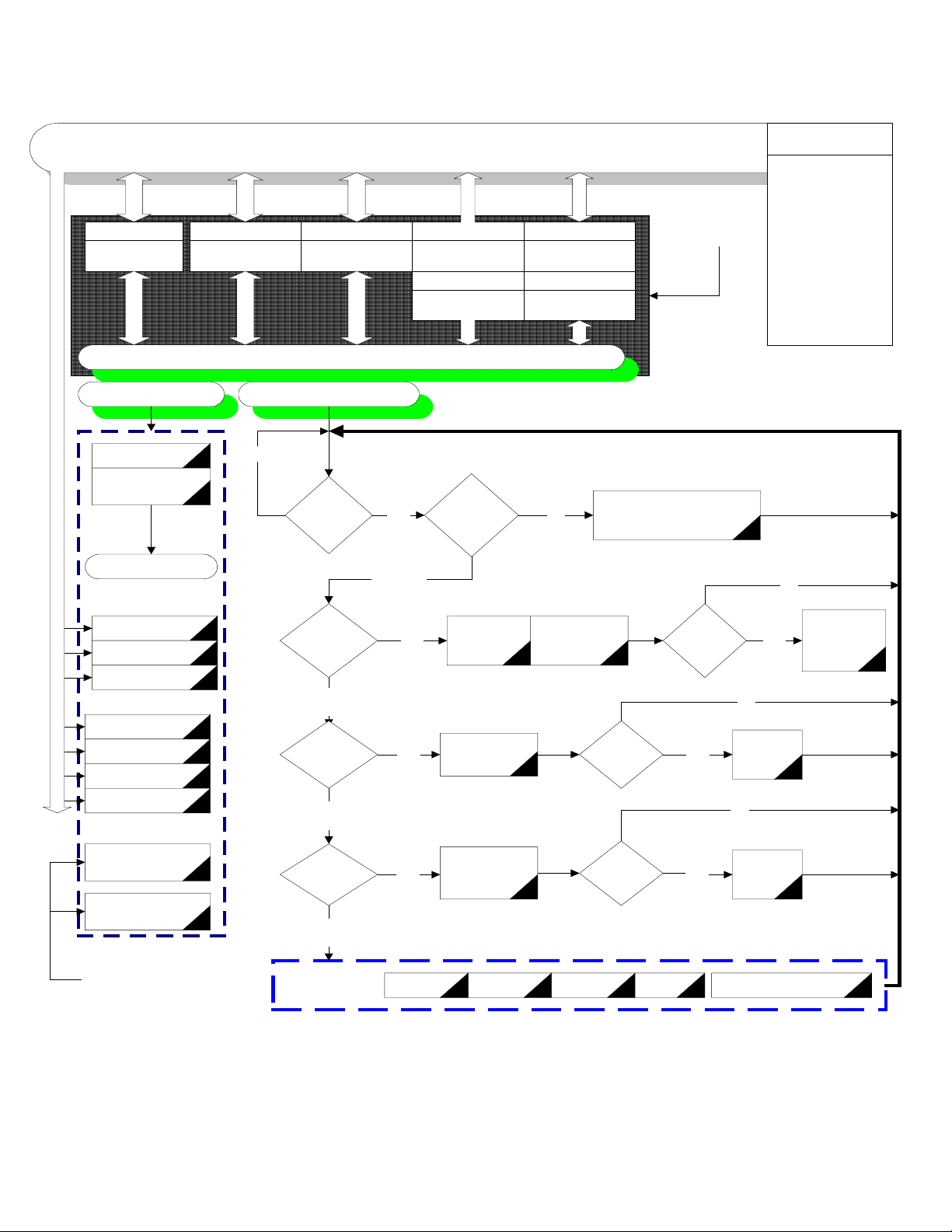
ACR-MOTIONMAX interfaces to the Parker-Acroloop Motion Card with 32bit Signal Banks provided on
the Motion Card. The Control system communicates with AcroBasic through the Matrix of 5 signal Banks
as shown in the following Chart. The Key bank of signals is the “Control Signals” (Bits 128 to 255) these
Signals are the Main interface between ACR-MOTIONMAX and the users AcroBasic programs.
The Strategy of the ACR-MOTIONMAX Software System is, “ACR-MOTIONMAX is a Core System
that’s designed to stay the same…you simply edit the AcroBasic programs and ACR-MOTIONMAX’s
Parameters to accommodate your particular application.
ACR-MOTIONMAX Control System Bit Signal Banks
Table 1:
Signal Bank Name Acroloop Bit Address’s Description
ControlSignals 128 to 255 Bit Addresses Reserved by ACR-MOTIONMAX
MCode Bits 1920 to 2047 MCodes … M00 to M127 Respectively
Master flags 512 to 544 Servo Motion State Flags
Inputs 0 to 31 …256 to 287 [Default … Ext. I/O Bank 1]
Outputs 32 to 63 … 288 to 319 [Default … Ext. I/O Bank 1]
M S & T Code Sequencing
ACR-MOTIONMAX Executes M S or T Codes by setting an M/S or T Code bit (1920-2047… M00-
M127) and an associated M/S or T Strobe Signal Bit. These bits are picked up by a looping P
and serviced.
rogram 1
5
All M S and T Codes Sent by ACR-MOTIONMAX are accompanied with a following M S or T
Strobe Signal.
The AcroBasic Program1 Intercepts M, S, T Codes and acts on them if its Strobe Signal is =1.
When the AcroBasic MS or T Code Function completes it must! set the associated Done Bit signaling
ACR-MOTIONMAX to continue.
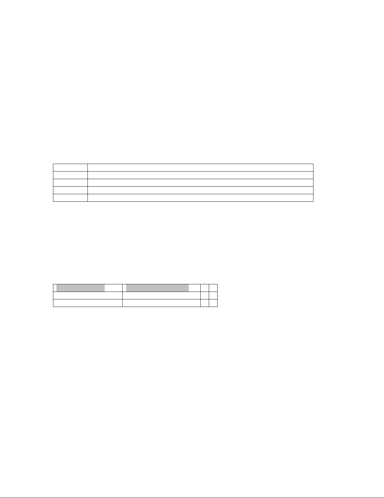
Strobe & Done Signals Table:
Signal Name Address Function
M Done 147 Set by AcroBasic when the M-Code is Completed
S Done 148 Set by AcroBasic when the S-Code is Completed
T Done 149 Set by AcroBasic when the T-Code is Completed
M Strobe 150 Set By ACR-MOTIONMAX along with MCode Bit Pointer of subroutine
to Execute
S Strobe 151 Set by ACR-MOTIONMAX along with the new Dac value in
DAC5(P6480)
T Strobe 152 Set by ACR-MOTIONMAX along with the new Tool code in
Counter5(P6775)
Jogging Functions
ACR-MOTIONMAX Handles all Jogging internally and uses parameters in the Parameters.Cfg file for
Normal and Fast Jog speed settings as shown below.
[JogSpeeds]
Acceleration=1
Deceleration=1
Velocity=100
Stp=1
[FastJogSpeeds]
Acceleration=1
Deceleration=1
Velocity=200
Stp=1
Page 6

ACR-MOTIONMAX Installation Guide
Homing & HandWheel
ACR-MOTIONMAX accomplishes two special machine functions Homing / HandWheel Step Mode
Functions by calling Subroutines in Prog0.8k Directly at assigned addresses, as shown in Diagram. 1.1
The user simply edits the AcroBasic code of the subroutines to accommodate their application. These
Functions are provided to facilitate the many types of homing a user may require. ACR-MOTIONMAX
simply calls the subroutines at dedicated address of prog0 to execute.
System Overview Diagram
6
Page 7
ACR-MOTIONMAX Installation Guide
7
Direct
Called
Functions
Control Signals
Bank 1
Bits 128 - 255
"User" AcroBasic Program Template Layout
(1-30)Initialazation
(40) Setup Gearing
Configuration
End of Prog
Bank 2
Bits 1920 to 2047
M Codes
No
Bits 512 to 544
Master Flags
Progam 1Program 0
Control
Ready
Bit 143
= 1 ?
MotionMax
Bank 3
Bits 0 to 31
Inputs Bank0
Bits 256 to 287
Inputs Bank 1
Line 5Line 4
Initialized
Yes
( Line 6 )
Bank 4
Control
Bit 145
=1 ?
Bank 5
Bits 32 to 63
Outputs Bank 0
Bits 288 to 319
Outputs Bank 1
NoYes
Parker
Acroloop
Controler
( 30000 )
Do Control Initialazation
MotionMax Internal
Functions
Operator Interface
GCode File Editor
G Code Processor
Graphics Engine
Overrides
ACR-MC Core Dll
ACR-MC
Parameters
Tool/Work Offsets
Diagnostics
MDI Functions
Jog/Homing
functions
No
(50) X1 Gearing
(60) X10 Gearing
(70) X100 Gearing
(100) X Homing
(200) Y Homing
(300) Z Homing
(400) 4 Homing
(1500) Move Z to
Tool Change Pos.
(1600) Spindle Orient
Program 1 Calls these
2 Functions
fot ToolChanges
ACR-MOTIONMAX to AcroBasic System Start up
MStrobe = 1
STrobe = 0
(Line 7)
No
SStrobe = 1
(Line 8)
No
TStrobe = 1
(Line 9)
No
( 10000 )
General Handler
(11 to 150 )
Yes
Yes
Yes
EStop Reset PB F-Hold PB
Parse
M-Code
( 8000-8999 )
Process
S-Code
( 9000 to 9999 )
Process
T-Code
(1000 to 7999 )
Do MCode
Functions
S Code
Process
Done ?
T Code
Process
Done ?
Over
Travels
M Code
Process
Done
?
Yes
Yes
Yes
No
Set S Done
No
Set T
Done
Error Msg. System
( 40500 )
Set M Done
Clear All M
Codes
Control Ready Bit (143) … This bit will Be Set =1 when ACR-MOTIONMAX initializes and is up
and running. This signal tells the AcroBasic program to start Looping as shown in figure 1.2.
Page 8
ACR-MOTIONMAX Installation Guide
Control Initialized bit (145)… Tells ACR-MOTIONMAX that the machine is initialized (Drives
Ready) and ready to Run. Insert your Drive Ready and any other initialization code in this function
(30000) to inform ACR-MOTIONMAX that initialization is complete and the machine is ready to run.
Program1 is the Main AcroBasic Program, all MS & T Codes are sent from ACR-MOTIONMAX and
processed in Program1 as shown.
ACR-MOTIONMAX AcroBasic Project Template Files
When ACR-MOTIONMAX is installed it will install an AcroBasic Template Project so the end user can
insert AcroBasic code into ACR-MOTIONMAX’s Predefined Structure of programs and subroutines to
form a repeatable control system. This Project is located in…
“C:\Program files\Parker\ACR-MOTIONMAX\AcroBasicFiles”
…and contains 5 files. Copy these files to your Acroview Default Project Folder.
AcroBasic Template Files list:
Prog0.8k: Sets Axis and Variable Definitions and Axis Homing and Spindle Orient Subroutines.
Prog1.8k: Contains the M S T Code Processing Code, and all other General Machine Functions.
PLC0.8k: Contains a Sample Lube System Code Ladder Program.
Sys.8k Defines System Memory Allocations on the Acroloop Card
Gains.8k Defines All initial Axis Gains.
8
Note: The Gains are overwritten when ACR-MOTIONMAX loads as ACR-MOTIONMAX uses the Gain
Settings
Defined in the Parameters.Cfg file so be sure to duplicate them in the Parameters.Cfg file.
Setting the Sys.8k file for Programs & Variable Memory Allocation
ACR-MOTIONMAX must be configured with enough memory in the SYS. 8k file, for the type of card
used.
PCI buss type cards use DPCB (Dual Port Cache Buffer), ISA buss type cards use FIFO (First in First Out)
Edit the 2 parameters of the SYS.8k file depending on the type of card your using (PCI is Default).
If using PCI Card If using ISA Type Card
Clear DPCB Clear FIFO
Dim DPCB (4096) Dim FIFO (4096)
Sys.8k File listing for PCI Type Controller
REM-----Clear out old allocations----SYS
HALT ALL
NEW ALL
CLEAR
DETACH ALL
REM-----Allocate system memory----DIM PROG0 (35000)
DIM PROG1 (35000)
DIM PROG2 (5000)
DIM PLC0 (5000)
DIM P (24)
DIM DEF (300) : REM Allocate Bit Variable Space for 300 Variables
CLEAR DPCB : REM Clear PCI Buss Type Cache Buffer
DIM DPCB (4096) : Rem Allocate for PCI Type Cache Buffer
REM - USER DEFINED AREA
:
Defining Bit Variables in AcroBasic
Page 9

ACR-MOTIONMAX Installation Guide
9
The Dim DEF (300) parameter in the
progo.8k to allow all bits to called with a Variable Name. No Punctuation is allowed in the variable name
and must be proceeded with #Define statement as shown. See Prog0.8k header.
Example & Format:
REM Input Bit Definitions
#DEFINE INPResetButton BIT0
#DEFINE INPFeedHoldButton BIT1
Sys.8k
should not be changed and is used in the AcroBasic file
M Code Sequence Examples:
ACR-MOTIONMAX MCodes (Bits 1920 to 2047) = M00 to M127
ACR-MOTIONMAX uses these bits to tell the AcroBasic Program which MCode Subroutine to Call.
Do not use any of these bits in your AcroBasic Programs they are reserved for ACR-MOTIONMAX
MCodes.
MCodes are triggered by Setting a MCode Bit (Bits 1920 to 2047) and an M Strobe Bit (150) signal bit.
Then the AcroBasic Program Prog1 will parse and call the appropriate MCode subroutine for execution and
return setting the MDone (Bit 147) Signal. ACR-MOTIONMAX will not execute another MCode or Gcode
if MDone = 0. See Prog1.8k line 6
M Code Sequence: M08 … Coolant On
[ACR-MOTIONMAX Sequence] [AcroBasic Action]
1) Sets bit 1928 M08 does nothing
2) Sets Bit 150 M Strobe 3) Parses the MCode bit and Calls Subroutine to be serviced
4) Returns with Mdone=1 and the Mstrobe=0 and Bit 1928=0
5) Continues
S Code Sequence: S2000
[ACR-MOTIONMAX Sequence] [AcroBasic S Code Handler Action]
1) Writes Dac5 Val to P6480 does nothing
2) Sets the Gear Range Bits
3) Sets the S Strobe Bit 151 4) Processes gear change if required
5) Enables Axis if was running previously with new Dac Value
6) Waits for Spindle to get up to Speed
7) Returns with S Done=1 and the S Strobe=0
T Code Sequence: M6 T2
[ACR-MOTIONMAX Sequence] [AcroBasic T Code Handler Action]
1) If new T Code is different Does nothing
From the Current tool then
Set 159 (ToolChangeRequest)
2) Set 1926 (M6 bit)
3) Set new Target into P6775
4) Set M Strobe ( Bit 150)
5) Set T Strobe (Bit 152) 7) Service M6 Code if ToolChangeRequest = 1
8) Clear ToolChangeRequest and M/T Strobe =0
9) Return with M/T Done Bits = 0.
Chapter 2 Setting up Installing ACR-MOTIONMAX
Install ACR-MOTIONMAX with the Install Program. (Install_ACR-MOTIONMAX.exe)
Page 10

ACR-MOTIONMAX Installation Guide
Print the following 2 Files for Reference after ACR-MOTIONMAX has been installed:
10
Reference Files
Print the following 2 files for reference:
“C:\Program Files\Parker\ACR-MOTIONMAX\Docs\Default Bit Definitions.xls.”
This file contains a Complete Bit Map of the ACR-MOTIONMAX System. This file is an Excel
spreadsheet for your reference and is your best resource to understanding how ACR-MOTIONMAX
communicates with the Parker-Acroloop Controller and AcroBasic.
“C:\Program Files\Parker\ACR-MOTIONMAX\Docs\Parameter_Definitionst.xls” in the ACRMOTIONMAX/Docs Sub Folder. This file describes the functions of all Parameters in the Parameters.Cfg
file that ACR-MOTIONMAX uses at runtime
ACR-MOTIONMAX Directory & File Structure:
Default Location … C:\Program Files\Parker\ACR-MOTIONMAX
ACR-MOTIONMAX.exe GUI Interface Program (The Graphical Operator Interface)
Core.Dll API Driven Core of ACR-MOTIONMAX (low level functions DLL File)
Parameter & Log files
Default Location … C:\Program Files\Parker\ACR-MOTIONMAX\Parfiles
Parameters.mdb Contains Machine Parameters (Used by ACR-MOTIONMAX Only)
Parameters.Cfg Contains Machine Parameters
I/O.Cfg Contains Control I/O Map
UserDefined.Err Contains User Defined Error Strings
ToolTables.Mdb Contains Tool Tables Database (Used by ACR-MOTIONMAX Only)
Tool.tbl Contains Current Runtime Tool & Offset Information
ViewPorts.Cfg Used By DLL to Define Zooming and Viewport Options at runtime.
MoveLog.txt Text file listing of all moves and Mcodes that ACR-MOTIONMAX executes.
User.txt Text log file of all functions that the operator does.
Sample Part files
Default Location … C:\Program Files\Parker\ACR-MOTIONMAX\Partfiles
Looping.nc
NestedLooping.nc
NestedSubProgramming.nc
SubProgramming.nc
Mold.nc
Pocket.nc
Manuals & Reference Documents
Default Location … C:\Program Files\Parker\ACR-MOTIONMAX\Docs
ACR-MOTIONMAX_Install_Guide.pdf This Manual
Programmers Reference Manual.pdf G-Code Reference Manual
ControlSignalsDef.doc Control Signals Reference Manual
Default Bit Definitions.xls The ACR-MOTIONMAX I/O Map Reference
MasterVectorInstructions.txt Servo Firmware upgrade instructions
Parameter_Definitionst.XLS Listing of all ACR-MOTIONMAX User Parameters
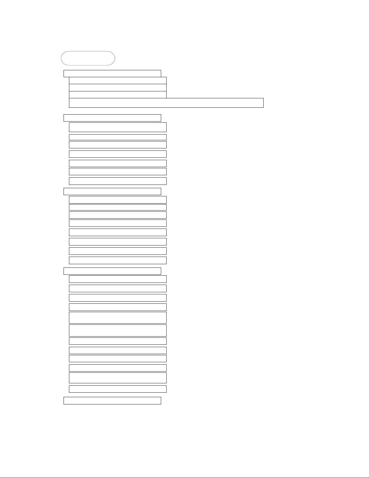
ACR-MOTIONMAX System Setup Diagram
Page 11
ACR-MOTIONMAX Installation Guide
Getting Started
Install AcroBasic SDK Software
Install MotionMax Software
Print Reference Manuals
Edit & Print Usert I/0 Map
Copy MotionMax AcroBasic Template Project to Acroview folder
Edit Acrobasic Program 0
Set Encoder Resolutions PPU
Set Encoder Multipliers MULT
Download to Servo Flash
Test & Phase Basic Servo Motion
Tune Servo Drives (Set Gains)
Configure Homing Functions
Configure I/0 Bit Variable Assignments
Save Setting to the Flash
Edit Acrobasic Program 1
Edit Initialzation Code
Edit MCode Functions M00 to M127
Edit S Code Function
Edit T Code Function
Edit Estop Function
Setup Error Msg System Strings
Test MCodes
Save Setting to the Flash
11
Edit MotiomMax Parameters.cfg
Configure #Encoder Resolutions
Configure #of Axis
Configure Gains
Configure Encoder Multipliers
Setup Speeds & Acceleration/
Deceleration
Setup Jog Speeds & Acceleration/
Deceleration
Configure ToolChanger
Configure Spindle Gear Ranges
Configure Inposition Bands
Configure Axis Backlash Values
Configure Axis Travel for Graphics
Display
Configure Overrides
Start Using MotionMax
Page 12
ACR-MOTIONMAX Installation Guide
Step 1. Install the Parker-Acroloop SDK (Software Development Kit)
Install the Parker-Acroloop SDK to your PC with the CD shipped with your Controller Card.
Important! When installing the SDK be sure to select the Type of Controller you’re using.
Step 2. Install ACR-MOTIONMAX to your PC
12
Install ACR-MOTIONMAX with the Install Program. (
Important!
Do not attempt to run ACR-MOTIONMAX attached to your machine until you have
Install_ACR-MotionMax.exe
)
completed the following tests in AcroBasic!
Disconnect all ServoMotors from any leadscrews or mechanism in case of axis runaway for the initial
setup phase.
Test Emergency Stop Circuitry & OverTravels
Emergency Stop Must Stop all Axis’s & (Spindle/Laser if equipped)
OverTravels Must Stop all Axis’s & (Spindle/Laser if equipped)
Set And Confirmed Encoder Resolutions and Multipliers
Phased the Motors Directionally
Set Axis Gains and can control Motors at the AcroView Command Line.
Duplicate the Encoder PPU / Gains Setting to the Parameters.Cfg file for ACR-MOTIONMAX
Important!
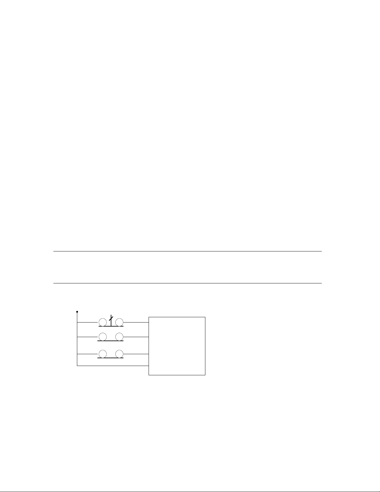
When handling OverTravels, most drives have 3 enables to aid in stopping an axis, Drive Enable,
Forward Enable and Reverse Enable.
Never simply cut main power to the drive in case of Emergency Stop or OverTravel.
Most Drives use Regenitive braking that is disabled if you cut power to the Drives.
If you simply cut the Power to the Drives they will just coast to zero speed and may destroy an Axis.
Instead of stopping the Machine in a Controlled Manner using the drives Internal Braking Power.
The idea here is “If your Amp can’t stop your Axis in a Controlled Manner, The Amp is to Small to
Control your Axis at Full Speed Accurately”.
Always Wire the OverTravels & Estop System into the Drive Enables as shown
Emergency Stop
Fwd. Over Travel Switch
Rev. Over Travel Switch
Servo Drive
Enable
Fwd. Enable
Rev. Enable
Signal Comm.
.
Page 13

ACR-MOTIONMAX Installation Guide
Step 3. Print Reference Files
Print the following 2 files for reference:
“
C:\Program Files\Parker\ACR-MOTIONMAX\Docs\Default Bit Definitions.xls.”
This file is a Complete I/O Bit Map of the ACR-MOTIONMAX System Signal Banks. This file is an
Excel spreadsheet for your reference and is your best resource to understanding how ACR-MOTIONMAX
communicates with the Parker-Acroloop Controller and AcroBasic.
“
C:\Program Files\Parker\ACR-MOTIONMAX\Docs\Parameter_Definitionst.xls
Parker\ACR-MOTIONMAX\Docs Sub Folder. This file describes the functions of all Parameters in the
Parameters.Cfg file that ACR-MOTIONMAX uses at runtime
” in the
Step 4. Load ACR-MOTIONMAX AcroBasic Project Template Files
Copy the 5 AcroBasic Template files
folder to C:\Program files\Parker\Acroloop\Acroview\Projects\Default folder. If you already have
code in the AcroView default folder it will be overwritten so back it up in necessary.
Open AcroView and Edit Prog0
Don’t Download to Card when prompted by Acroview yet.
Edit Prog0 @ 6 and configure the Axis Encoder Resolutions and Multipliers
Set the PPU Values (Encoder Resolution) for your application… Units = XXXX Counts per 1” of
travel.
Example: PPU X4000 Y4000 Z4000
Mult X1 Y1 Z1
contained in the ACR-MOTIONMAX\AcroBasic sub
13
Step 5. Download Project to Controller Flash.
Download All AcroBasic Programs to the Servo Cards Flash and save it with (No Errors).
Note: to enable error checking … right click in the lower window and select “Logging”. Next
download the file to the card. AcroView writes a log file that resides in the AcroView folder.
Open this file with notepad or create a shortcut to it on your desktop, as you will probably look at
this file hundreds of time to check the program for errors.
When all Programs are Downloaded Error Free. Type the Following at the Command line.
Flash Save
ESave
Step 6. Test & Phase the Motor/Encoders
Phasing is correct when the Axis Readout Increments when moved in a positive direction on your machine.
Enable your Drives manually and type the following at the Command line:
While watching the Readouts on the Top Upper left of the AcroView Screen.
Repeat for All Attached Axes.
Prog0
X1
The X Axis Motor should move 1 inch positive, and in a direction you consider to be Forward on your
Machine. If it doesn’t the Motor is Out of Phase and the Mult Parameter/Encoder or DAC lines will need to
be changed.
To Change Motor Direction using Parameters:
Set the MULT Parameter to –1 for the Axis Axis0 MULT –1
Reverse the Dac Gain for the Axis Dac0 Gain -3276.8
Page 14

ACR-MOTIONMAX Installation Guide
Down load Program0 again and test.
Step 7. Tune Axis Gains
Keys: Load Encoder Parameters in the AcroView watch window [Actual Position]
Do a Series of moves to a safe Distance and back to Zero observing the Encoder Feed back while Setting
the Gains to it finishes at +/- 1 Encoder Pulse from it Trajectory Target.
Set PGain in the AcroView Gains Parameters
PGAIN AXIS0 0.002441 (Default Value)
Set all other Gain Parameters to 0 for the axis under test.
Slowly increase PGAIN till Axis oscillates then back down till Oscillation stops and go a little extra.
Move the Axis 5 inches … Example: X/10
Observe the Actual Encoder Position it should be Short at this point.
14
Next Increase IGAIN to by factors of .1 and index in the Axis to X10 and then back to X0.
The Actual Position should start to get closer to the Target in the upper Top Left Readout Target.
Next Increase ILIMIT to by factors of .1 and index in the Axis to X10 and then back to X0.
The Actual Position should start to get to +/-1 Counts of the Target in the upper Top Left Readout Target.
Next Increase DGAIN in small increments to dampen the move if it is slamming into position.
Note: XY Systems must have the Gains Set Exactly the Same for Coordinated Motion to be precise.
The Preceding is a general format for tuning and not by any means the only way to tune an axis.
Repeat For All Attached Axes’.
Page 15

ACR-MOTIONMAX Installation Guide
Step 8. Update ACR-MOTIONMAX Parameters with the Current PPU
/ Gains Settings
ACR-MOTIONMAX uses the following text file for its parameters.
“C:\Program Files\Parker\ACR-MOTIONMAX\Parfiles\Parameters.Cfg”.
Open this file with Notepad and edit the following 2 Sections
1). Edit “SystemResolution” Values to be the same as the PPU Value you have in Program 0.
This value must be in Pulses per Inch/Millimeter of Axis Travel.
[SystemResolution]
0PulsesPerUnit=4000
1PulsesPerUnit=4000
2PulsesPerUnit=4000
3PulsesPerUnit=0
4PulsesPerUnit=0
5PulsesPerUnit=4096
6PulsesPerUnit=0
7PulsesPerUnit=0
2). Edit “Gain” Values to be the same as the Gains values you have in AcroView for all Axes.
Note: Make sure you Edit the gains for all attached axes you will be using for you application.
15
[Gains0] Axis0 Gains Sample Values
PGAIN=0.02
IGAIN=0.01
ILIMIT=0.01
IDELAY=0
DGAIN=0.000001
DWIDTH=0
FFVEL=0
FFACC=0
TLM=10
Repeat for Gains1/Gains2/Gains3 Sections etc.
Save the File and Exit notepad.
Page 16

ACR-MOTIONMAX Installation Guide
Step 9. Configure Homing Functions
Homing is accomplished by program0 at dedicated Address that ACR-MOTIONMAX will call
directly behind the scenes. The user simply inserts his actual homing code into the appropriate
Function as follows.
ACR-MOTIONMAX reads the Homing Status bits to disallow other functions while homing is Active.
A homing Sequence shall
1) Set the Axis Homing bit when started. Ex: Set 144 … sets the Homing Active bit to ACR-
MOTIONMAX.
2) Clear the Axis Home bit when started Ex: Clr 170 … Clears the X home Done Bit to ACR-
MOTIONMAX.
3) When Homing is complete … Ex: Set 170 … Sets the Axis Homed Bit to ACR-MOTIONMAX.
Homing Direct Called Subroutine Address’s in Program0
Function Called Address in Program 0
Axis0 Homing “X” 100 to 199
Axis1 Homing “Y” 200 to 299
Axis2 Homing “Z” 300 to 399
Axis3 Homing “4
Th Axis
” 400 to 499
16
Homing Status Bits of the Control Signals
Function Control Signals Bit
Homing Active Bit 144
Axis0 Home Done “X” 170
Axis1 Homing “Y” 172
Axis2 Homing “Z” 173
Axis3 Homing “4
Axis 0 Homing Example Code:
REM ***[ X HOMING FUNCTION ]*****************************************************
REM BIT 170 = X HOME DONE
REM BIT 15 = X HOME LIMIT SWITCH (NORMALY Closed SWITCH)
100 SET 144: GEAR RES X: JOG RES X: vector 0: REM Set the Homing Active Control Bit
101 ACC 10 : REM Set Acceleration ramp value
102 DEC 10 : REM Set Deceleration ramp value
103 STP 10 : REM Set stop ramp value
104 CLR 170 : REM CLEAR THE X REFRENCE DONE BIT TO->CNC
105 VEL 3: CLR 2053: ROV 1: FOV 1 : REM Set velocity toward home switch
106 INT -15 X (100,0) : REM *START MOVING TILL LIMIT SW. GOES
107 INH -516
109 VEL .2 : REM
130 INT 15 X (-12,0) : REM *GO TILL OFF LIMIT SWITCH AND STOP
131 INH -516
140 VEL .25 : REM *SET VEL TO SEEK THE MARKER PULSE
141 JOG RES X
145 MSEEK X (-12,0) : REM *Initiate a marker seek operation AND ZERO CONTROLLER
151 RES X : REM *MARKER FOUND, ZERO X POS REGISTERS
153 REN X : REM *MAKE CURRENT X POS ZERO
154 VEL 1: MOV X -. 5 : REM THIS ISTHE HOME OFFSET VALUE
155 INH –516 : REM WAIT FOR MOTION TO STOP
156 JOG RES X: RES X: REN X : REM ZERO POSITION TO ABS 0
Th Axis
” 174
Page 17

ACR-MOTIONMAX Installation Guide
157 MOV X 0 : REM SET 0 AS TARGET and Zero Readout
180 SET 170 : REM SET X REFRENCE DONE BIT TO->CNC (!! HOME NOW DONE !!)
185 CLR 144: SET 2053 : REM Clear the Homing Active Control bit
199 GOTO 10000 : REM EXIT PROGRAM 0
Step 10. Configure I/0 Labels for ACR-MOTIONMAX Diagnostics
Open the file “C:\Program Files\Parker\ACR-MOTIONMAX\Parfiles\IO.Cfg”.
This File is used for the ACR-MOTIONMAX Diagnostics Feature, it allows the user to Define their i/o for
viewing in ACR-MOTIONMAX Diagnostics.
Fill in the Values to Right of the Equals Sign Only!
Do not edit anything to the Left of the Equals Sign.
Edit these sections to Create Labels for your I/O in ACR-MOTIONMAX Diagnostics.
IO.Cfg File Excerpt:
[CncInputsConfig]
INP0 =Reset PB
INP1 =Feedhold PB
INP2 =Cycle Start PB
INP3 =Estop PB
17
INP63 = Open Input
[CncOutputsConfig]
Out0 =PC On Lamp
Out1 =Cycle Start Lamp
Out2 =Feed Hold Lamp
Out3 =Reset Lamp
Out63 = Open Output
Page 18

ACR-MOTIONMAX Installation Guide
Step 11. Edit the Control Initialization Subroutine
When Program 1 starts, it looks at the Control Signal bit 145 (Control Initialized) to see if the machine
has been initialized. If this Bit = 0 Program 0 will call the Subroutine at Line 3000 and set the bit when it
Exits.
The User should place any initialization Code in this function to tell ACR-MOTIONMAX the Machine is
Ready to Run. As the Diagram below shows the program will not start until the following 2 conditions are
met.
1). ACR-MOTIONMAX is up and running Bit 143 =1 (Control Ready).
2). The AcroBasic Has initialized Bit 145 =1 (Control Initialized)
Progam 1
No
Line 5Line 4
Control
Ready
Bit 143
= 1 ?
Control
Initialized
Bit 145
=1 ?
NoYes
( 30000 )
Do Control Initialazation
18
Yes
Example:
REM ***************************************
REM *** CONTROL INITIALIZATION FUNCTION ***
REM ***************************************
30000 SET OUTSpindleReady: PON
30001 SET OUTDrivesReady
30002 SET OUTSpindleEStop: P6480= 0: AXIS5 OFF: CLR 190
30003 SET CTLInitialization
Insert Your Machine Initialization Code Here
30086 CLR 170: CLR 171: CLR 172: CLR 173: CLR 174: CLR 175: Rem Clear Strobes & Done bits
30087 P4156= 0: P4157= 0: P4158= 0: P4159= 0: REM CLR MCODES
30088 SET CTLMDone: SET CTLSDone: SET CTLTDone: CLR CTLMStrobe: P10= 0
30089 CLR CTLSStrobe: CLR CTLTStrobe: CLR CTLUserErrorReq
30090 RETURN
Page 19

ACR-MOTIONMAX Installation Guide
19
Step 12. Edit the M Code Functions
ACR-MOTIONMAX is set up to Provide 128 User definable MCodes.
They are set By ACR-MOTIONMAX via the MCode bits Bank of Signals (Bits 1920-2047)
When ACR-MOTIONMAX encounters A MCode it Parses the Code and sets a corresponding Bit of the
MCode Signals to Tell AcroBasic which Subroutine to Call.
For Example M00 = Bit 1920 … Bit 1921 = M01 and so on.
Also ACR-MOTIONMAX will set the MStrobe Bit (Bit 150).
Program 1 will see the Strobe Signal = 1 and Parse the MCode Bit and call the proper subroutine to execute
the desired MCode Function.
Rules of operation:
All MCode functions are executed at Dedicated Address of
All MCode functions are called from the MCode Parsing function Starting at line 11.
The Template Provides 128 MCode Subroutines.
These subroutines are 50 lines long.
Do not Exceed this limit of 50 lines or the parser will call the wrong function.
For Example: M00 subroutine is at Address 1000 to 1049 as shown in the Code Below.
REM ***********************************
REM *** MCode EXECUTION SUBROUTINES ***
REM ***********************************
Program 1
Starting at Address 1000.
REM ~ M00
1000 CLR CTLInCycle: REM Set program stop
1001 GOSUB 40500 :REM CLEANUP MCODES
1049 RETURN
REM ~ M01
1050 IF (CTLOptStopActive) THEN CLR CTLInCycle: REM set optional program stop if active
1096 GOSUB 40500: REM CLEANUP MCODES
1099 RETURN
Progam 1
No
Line 5Line 4
Control
Ready
Bit 143
= 1 ?
MStrobe = 1
STrobe = 0
Yes
( Line 6 )
Yes
Control
Initialized
Bit 145
=1 ?
(11 to 150 )
Parse
M-Code
NoYes
(1000 to 7999 )
Do MCode
Functions
( 30000 )
Do Control Initialazation
M Code
Process
Done
?
Yes
No
( 40500 )
Set M Done
Clear All M
Codes
Page 20

ACR-MOTIONMAX Installation Guide
20
Step 13. Editing the S Code Function
When ACR-MOTIONMAX Encounters a SCode … Example: S2000.
It will do the following Steps.
1). Check if the Requested Spindle Speed is different from the Current Spindle Speed.
2). If it is it then checks if the Speed is within the current Gear Range as defined in the Parameters.
3). If the new Speed requires a different Gear, ACR-MOTIONMAX will set the Binary code of the Gear
Range to be in.
4). If Gear Change is Required then the AcroBasic shall stop the spindle and switch to the new Gear Range.
5). If the spindle was previously running (SpindleRunning Bit 190 =1) then the function will restart the
spindle and wait till its running at the commanded speed.
6). If the spindle wasn’t previously running (SpindleRunning Bit 190 =0) the function should write the
Dac value but not restart the spindle.
7). The function then Clears the S Strobe and sets the S Done bits to Signal ACR-MOTIONMAX to
continue.
Parameters Gear Range Section of the Parameters File
[SpindleOptions]
SpindleGears=3
SpindleMaxRPMGearRange0=1000
SpindleMaxRPMGearRange1=2000
SpindleMaxRPMGearRange2=4000
SpindleMaxRPMGearRange3=4000
Control Signals used with S Codes:
S Strobe Bit 151 Set by ACR-MOTIONMAX to Trigger the SCode
Handler Function
S Done Bit 148 Set by AcroBasic when S function is completed
SpindleRunning Bit 190 Tells AcroBasic if spindle was Previously Running
GearChangeActive Bit 176 Set in AcroBasic to Signal a Gear change is occurring
GearRangeBit0 Bit 177 LSB of 3 bit Binary code of Gear Range
GearRangeBit1 Bit 178 Binary code of Gear Range
GearRangeBit2 Bit 179 MSB of 3 bit Binary code of Gear Range
Axis5 Dac (Spindle Axis) P6480 ACR-MOTIONMAX Writes this as the Spindle
Speed
REM ********************
REM *** S Strobe Sub ***
REM ********************
8000 IF (NOT CTLMDone) THEN GOTO 8990
8010 IF (NOT CTLTDone) THEN GOTO 8990
8011 IF (CTLTStrobe) THEN GOTO 8990
REM ~ STORE D/A, CLR SPINDLE ORIENTED SIGNAL, SAVE STATE OF SFWD/SREV
8013 P3 =P6480: P4= OUTSpindleForward: P5= OUTSpindleReverse: AXIS5 OFF
Insert Your S Code & Gear Change Logic Code Here
REM IF SPINDLE WAS RUNNING, RESTORE D/A AND DIRECTIONS & WAIT FOR UPTOSPEED
8351 IF (BIT 190) THEN P6480= P3: OUTSpindleForward= P4: OUTSpindleReverse= P5: INH 259:
GOTO 8420
REM ~ ELSE CLR FWD & REV ENABLES & reset D/A
8352 OUTSpindleForward: OUTSpindleReverse: P6480= P3
REM ~CLEAN UP
8420 SET CTLSDone: CLR 183 : REM Set SDONE, clear spindle oriented bit
Page 21

ACR-MOTIONMAX Installation Guide
8430 CLR CTLSStrobe : REM Clear SSTROBE
8440 CLR CTLGearChgActive : REM Clear the Gear Change Request bit
8990 RETURN
21
Page 22

ACR-MOTIONMAX Installation Guide
Step 14. Edit the T Code Function
ACR-MOTIONMAX Handles Tool Codes by loading the AcroBasic Counter 7 (P6775) with the
Requested Tool number. If The Requested Tool is different From the Current then ACR-MOTIONMAX
will Set the ToolChangeRequest bit (159) to tell the ToolChange function to effect a Tool Change.
ACR-MOTIONMAX is designed to accommodate 3 types of tool Changers:
Type 1) Basic Knee Mill with no Tool Changer
Type 2) Standard Tool arm No Pre-Stage Arm
Type 3) Pre Staging with Virtual Tool Lookup
If using a Type 1 note: You must post a User Message to the system from inside the T Strobe Handler
that prompts the Machine Operator to “Please Change to Tool Number ”. See Error Message System
ACR-MOTIONMAX will see that a Tool change is in progress and will append the new Tool number
to the end of your Message, with a “Press Ok to continue”. This allows you to Change tools even
though you have no tool changer … except for the machine operator.
Type 2 & 3 are handled by ACR-MOTIONMAX, all the machine builder needs to do is write his M06
Code and T Code Handler.
22
T Strobe Bit 152
T Done Bit 149
ToolChangeRequest Bit 159
RequestedToolPositon
CurrentToolPosition in Magazine P6759 Holds the Current Magazine Position in Pockets
TooChangeDone Bit 154 Set by AcroBasic to signal Tool Change Completion
ToolChangeActive Bit 153 Set by AcroBasic to Signal Tool Change in progress
Note: M06 TXX Code ACR-MOTIONMAX will Set the M6 code first then the Tcode to allow
the M6 to Be processed first. See M06 function for Details and logic.
The Main purpose of the Tcode is to Rotate the Magazine to the New Tool Pocket for Changing to the
Spindle.
Example: This example is using the Type3 ToolChanger (Virtual Pockets with Pre-Stage arm)
REM ********************
REM *** T Strobe Sub ***
REM ********************
REM TOOL POCKET HANDLER
REM USES PLC COUNTER # 7 @ ADDRESS 6775
9000 IF (NOT INPConsoleEstop OR INPResetButton) THEN GOTO 10000
9001 IF (CTLMagRefDone) THEN GOTO 9020
9010 IF (NOT CTLMagRefDone) THEN SET OUTRotateMagazine: SET 152: CLR 149
9011 IF (INPMagazineHome) THEN P6759= 1: SET CTLMagRefDone
9012 CLR OUTRotateMagazine: DWL 1
9012 GOTO 9390
P6775 Loaded by ACR-MOTIONMAX with the Target in
Set by ACR-MOTIONMAX to trigger Tcode Handler
function
Cleared by AcroBasic when ToolChange is Done
Set by ACR-MOTIONMAX to Indicate a Tool
Change is Required
Pockets
9020 SET OUTRotateMagazine: SET 156: SET 152: CLR 149
9025 IF (P6759 <> P6775) THEN SET OUTRotateMagazine: GOTO 9390
9027 CLR OUTRotateMagazine
9326 CLR CTLTStrobe
9328 CLR OUTRotateMagazine
Page 23

ACR-MOTIONMAX Installation Guide
9330 SET CTLTDone: REM Set TDone
9390 RETURN
Step 15. Edit the Emergency Stop Function
23
This Subroutine is called by the
Estop Button is Pressed.
KeyBit = Estop (Bit 129) of the Control Signals
The ACR-MOTIONMAX GUI uses this signal for Emergency Stop Status display to the
Operator
If this bit = 1 then the Emergency Stop Indicator at the bottom of ACR-MOTIONMAX will
blink.
If this bit = 0 then the Emergency Stop Indicator at the bottom of ACR-MOTIONMAX will
clear.
Program1:
REM ****************************
REM ***
REM ****************************
REM ~ Set EMERGENCY STOP
10000 IF (NOT INPConsoleEstop AND NOT CTLEStop) THEN GOSUB 40000
REM ~ Clear EMERGENCY STOP
10010 IF (INPConsoleEstop AND CTLEStop) THEN CLR CTLEStop: CLR 522: DWL 1
General Control Loop
General Handler of Program 1, Line 10000 & 10012
***
when the
REM *******************************
REM *** EMERGENCY STOP FUNCTION ***
REM *******************************
40000 SET CTLEStop: AXIS5 OFF: P6480= 0: CLR 190: SET 523
40001 CLR 150: CLR 151: CLR 152: SET 147: SET 148: SET 149
40002 SET CTLReset: CLR CTLHomeXDone: CLR CTLHomeYDone: CLR CTLHomeZDone: CLR
CTLHomeADone
40003 RES AXIS0 AXIS1 AXIS2 AXIS3 AXIS4: P10= 0
40005 P4156= 0: P4157= 0: P4158= 0: P4159= 0
40006 P10= 0
40007 CLR CTLUserErrorReq: P4156= 0: P4157= 0: P4158= 0 : P4159= 0
Insert Your Emergency Stop Code Here
40008 RETURN
Page 24

ACR-MOTIONMAX Installation Guide
Step 16. Configure the AcroBasic to ACR-MOTIONMAX User Error
Msg. System
ACR-MOTIONMAX is Capable of Posting Error Messages generated from AcroBasic using the
following bits of the Control Signals.
Error System bits of the Control Signals:
Error Message Pending Bit 249
User Error Request Bit 250
User Error Bit 1 Bit 251
User Error Bit 2 Bit 253
User Error Bit 3 Bit 254
User Error Bit 4 Bit 255
User Error Bit 5 Bit 256
ACR-MOTIONMAX Contains a Text File called UserDefinedError.txt that Contains Error Messages
to be sent to the Control Display. User Error System Works by Setting the Desired User Error Code
Bits, and then Setting Bit (250) User Error Request to Signal ACR-MOTIONMAX to Decode the
Message.
When ACR-MOTIONMAX Finds Bit 250 =1 it will decode the 5 User Error bits and Display the
Message on the ACR-MOTIONMAX Screen with and OK button. Next the user must acknowledge
the Error by pressing OK. When the User Presses OK, ACR-MOTIONMAX will clear the Error
Request Bit 250. If another error is pending it will be displayed.
Reserved (Used by DLL for G Code Error Messages )
Set by AcroBasic to Trigger GUI to Display ERR. MSG.
LSB of binary bit code of Error messages
LSB of binary bit code of Error messages
24
Example: To set A lube Alarm
The Lube Alarm Message is at Position 3 in our file, so we need to set the Error Bit Code to Binary 3
as shown.
Set 251: Set 252 : Rem Set Error Pointer to Message 3
Set 250 : Rem Trigger GUI to Display Error Message 3
Note: UserDefinedError.err found in
C:\Program Files\ACR-MOTIONMAX/Parfiles\UserDefinedError.txt
Sample UserDefinedError.txt for reference
User ALARM: Spindle Chiller Fault! Please check.
User ALARM: Low or No Air Pressure! CNC can’t run without 60psi min.
User Alarm: Lube Level Low!
User ALARM: Z Not @ T-Change Position for Pending M6
Page 25

ACR-MOTIONMAX Installation Guide
Step 17. Configure Valid Mcodes List for ACR-MOTIONMAX
Mcodes Are Validated in ACR-MOTIONMAX to prevent erroneous Mcodes from running in a G Code
Program.
All Valid Mcodes must be Edited/Set in the Parameters [MCodes] section of the Parameters.Cfg file.
Set to 1 to enable Mcode … Set to 0 to disable Mcode
Enter Mcode Description
Sample Parameters.Cfg file
[
MCodes
M0=1
DESC0=OPTIONAL PROGRAM STOP
M1=1
DESC1=PROGRAM STOP
M2=1
DESC2=PROGRAM STOP
M3=1
DESC3=SPINDLE FWD
M4=1
DESC4=SPINDLE REV
M5=1
DESC5=SPINDLE STOP
M6=1
DESC6=TOOL CHANGE
M7=0
DESC7=
M8=1
DESC8=COOLANT ON
M9=1
DESC9=COOLANT OFF
]
25
M126=1
DESC126=TURN ON TAPPING MODE
M127=1
DESC127=TURN OFF TAPPING MODE
Important: if ACR-MOTIONMAX encounters an invalid Mcode in a G Code
program an Error will be displayed as to which Mcode is invalid.
A Gcode program must contain all valid MCodes to be run.
Page 26

ACR-MOTIONMAX Installation Guide
26
Step 18. Configure Key ACR-MOTIONMAX Parameters
ACR-MOTIONMAX uses a File for all Machine Parameters… Filename Parameters.Cfg
For Initial Start Up several key parameters Sections need editing. The Following is a list of the key
parameters needed to initially get ACR-MOTIONMAX up and running. After completing the edits save the
file and Start ACR-MOTIONMAX for the first time.
Section Name
[CNC_CONFIG] Description Default
Mill=1 Set to 1 for Mill or 0 for Lathe 1
NumberOfAxis=3 Sets the Number of Axis ACR-MOTIONMAX is to
Control
InchMetricMode=1 Set to 1 Inch or 0 for Metric 1
[SoftwareOptions] Default
AxesDisplayOn=1,1,1,0,0 Set to 1 to Make Axis Visible in ACR-
MOTIONMAX
AxisDesignation0=X Axis Letter X
AxisDesignation1=Y Axis Letter Y
AxisDesignation2=Z Axis Letter Z
AxisDesignation3=C Axis Letter B
3
1,1,1,0,0
[SoftwareOptions] Default
AxesDisplayOn=1,1,1,0,0 Set to 1 to Make Axis Visible in ACR-
MOTIONMAX
AxisDesignation0=X Axis Letter X
AxisDesignation1=Y Axis Letter Y
AxisDesignation2=Z Axis Letter Z
AxisDesignation3=C Axis Letter B
UseADCChanelForOverrides=0 Specifies to Control System that
Overrides are Derived From the ADC
channels
RapidOverrideMax=100 Sets the Max that the Override can be
set to
FeedrateOverrideMax=200 200
SpindleSpeedOverrideMax=150 150
RapidOverridePotVoltage=5 Specifies to Control Max DC Voltage
Derived From the ADC channels
FeedrateOverridePotVoltage=5 5
SpindleSpeedOverridePotVoltage=5 5
FeedOverrideType=98 Specifies the Type of Override used
0=Analog POT 1=4bit POT 98=Use
Screen Sliders Only 99=Hardcode to
Overrides Max values
RapidOverrideType=98 98
SpindleOverrideType=98 98
MachineXLength=60 Set X Length of your Machine Travel 24
MachineYLength=30 Set Y Length of your Machine Travel 24
MachineZLength=30 Set Z Length of your Machine Travel 24
1,1,1,0,0
0
100
5
98
Page 27

ACR-MOTIONMAX Installation Guide
[SpindleOptions] Parameter Description Default
SpindleEncoderInstalled=0 Set to 1 if Spindle Encoder Equipped 0
SpindleDAMaxVoltage=9 Max Voltage for controller to Output to
spindle Drive
RigidTappingInstalled=0 Set to 1 if Machine Has Spindle Encoder
for Rigid Tapping
OrientBeforeTap=1 Set to 1 to Force an M19 on every Tap
Cycle
SpindleGears=2 Set to The Number of Gears on the
Spindle
SpindleMaxRPMGearRange0=1050 Sets Max. Speed of Gear Range 1000
SpindleMaxRPMGearRange1=4100 Sets Max. Speed of Gear Range 4000
SpindleMaxRPMGearRange2=4100 Sets Max. Speed of Gear Range 4000
27
9
0
1
2
SpindleMaxRPMGearRange3=4100 Sets Max. Speed of Gear Range 4000
[ToolChanger] Parameter Description Default
ChangerInstalled=0 Specifies that Machine is Equipped with a
ToolChanger
NumberOfToolPockets=24 Specifies Total Number of Pockets in Magazine 24
BiDirectionaMagazine=0 Set to 1 if Magazine is Bi-directional…. Used for
Shortest Path to Tool Lookup
VirtualPockets=0 Set to 1 for Virtual Tool Pocket Lookup Strategy
Type
[Speeds] Parameter Description Default
Acceleration=10 Sets Machine Acceleration 10
Deceleration=10 Set the Same as Acceleration 10
Velocity=450 Sets Machine Max Speed in inches per min. 400
Stp=10 Set the Same as Acceleration (For Trap Profile) 10
[JogSpeeds] Parameter Description Default
Acceleration=1 Sets Machine Acceleration 1
Deceleration=1 Set the Same as Acceleration 1
Velocity=100 Sets Normal Jog Speeds 100
Stp=1 Set the Same as Acceleration 1
0
0
0
[FastJogSpeeds] Parameter Description Default
Acceleration=1 Sets Machine Acceleration 1
Deceleration=1 Set the Same as Acceleration 1
Page 28

ACR-MOTIONMAX Installation Guide
Velocity=150 Sets Fast Jog Speeds 150
Stp=1 Set the Same as Acceleration 1
Step 19) Configure the Overrides
Note: These Parameters are set from Parameters Section [SoftwareOptions]
____________________________________________________________________
To Configure for Type 0 Override (Using Analog 10k Pot’s on Control Panel)
1. Set UseADCChanelForOverrides = 1
2. Set all 3 Override Types to = 0
3. Set all 3Max Override Value Parameters
4. Set all 3 OverridePotMaxVoltage Parameters
____________________________________________________________________
To Configure for Type 1 Override (Using Digital 4 Bit Pots on Control Panel)
1. Set UseADCChanelForOverrides = 0
2. Set All 3 Override Types to = 1
3. Set Max Override Value Parameters
4. Write code in AcroBasic that Sets the Digital_OVR bits of the Control Signals when digital pots
are rotated.
_____________________________________________________________________
(Default Mode)
To Configure for Type 98 Override (Using VB Screen sliders Exclusively for Overrides)
28
1. Set UseADCChanelForOverrides = 0
2. Set All 3 Override Types to = 98
3. Set Max Override Value Parameters
_____________________________________________________________________
To Configure for Type 99 Override (Hardcode Overrides to Max Values)
1. Set UseADCChanelForOverrides = 0
2. Set All 3 Override Types to = 99
3. Set Max Override Value Parameters (These Values will Be Constant for the Overrides)
Page 29

ACR-MOTIONMAX Installation Guide
Step 20. Starting ACR-MOTIONMAX for the First Time
When ACR-MOTIONMAX starts it will display several messages as follows:
29
Card not found
but motion is not possible.
Parameter Error “Parameter XXX Has Failed” … a parameter has failed its type check…. Edit the
Parameters.Cfg file to correct and try again.
Demo Version you have XX Days to register this software
MOTIONMAX is shipped as a Demo Version that the User will Call Axuim controls to Register it for
unlimited use. If you don’t Register ACR-MOTIONMAX it will disable at the end of its Term of Demo.
Demo Version has expired
must Call Axuim controls to Register it for unlimited use. If you don’t Register ACR-MOTIONMAX it
will disable at the end of its Term of Demo.
… this happens is if no Servo Controller is found in the PC, the software will still run
. …
This is normal
. … This means the Demo has expired and the software is unusable. You
, ACR-
Important
To Register the Software
option.
This will display a Dialog with a Code number. Call or email Parker-Hannifin with this Code Number to
Unlock your Demo Version or Enable new Features as you purchase them.
Goto the “Help” PullDown Menu and select the Register Software
Running ACR-MOTIONMAX for the First Time
Step 1) Test Jogging
Release Estop and select Jog Mode and Jog all Axis + and minus to confirm Machine Axis
Operation.
Step 2) Test Homing
Home each individual Axis first before selecting HomeAll. This confirms that the homing
functions are working correctly. Close the Jog Screen.
Step 3) Test Inputs and Outputs in Diagnostics
Select Diagnostics mode and Set and clear each Output to confirm outputs operation using the
On off buttons in the upper left of the Diagnostics Screen. Also watch and confirm the associated
Inputs as the Outputs are toggled for correctness.
Step 4) Select MDI Mode Test Mcodes
Enter some basic Mcodes such as M08 (Coolant On) and M09 Coolant Off. This will test your
AcroBasic Mcode functions. Correct Errors as required and try again. Remember ACR-
MOTIONMAX must be closed to Open Acroview.
Step 5) Test Basic G Code Motion from MDI Mode Screen G0 & G01
Enter the Following in the MDI Screen command line:
G01 X5 F10 … Press Enter … the axis should move to X5 at a feedrate of 10 inches per min.
G00 X0 … Press Enter the X axis should Rapid to X0 at the Feedrate specified in the Speeds Parameter
Velocity (This is the Rapid and Max Feedrate for all Axis)
Page 30

ACR-MOTIONMAX Installation Guide
Appendix A. ACR-MOTIONMAX Parameters
This is the Complete Parameter List for reference.
[CNC_CONFIG] Description Default
ParameterPassword=CNC Used for Parameter & Diagnostics Password CNC
Mill=1 Set to 1 for Mill or 0 for Lathe 1
NumberOfAxis=3 Sets the Number of Axis ACR-MOTIONMAX is to
Control
InchMetricMode=1 Set to 1 Inch or 0 for Metric 1
HandWheelInstalled=0 Set to 1 in using Remote Pendant 0
UserEditorPath=notepad.exePointer to the User configurable Editor Path
30
3
ConversationalProgPath=n
otepad.exe
AbsoluteArcCenters=1 Set to 1 if using ABS Arc Centers else set to 1 for
PartFilesPath=C:\Program
Files\ACRMOTIONMAX\Partfiles
LastFile= Pointer to the Last File Opened by ACR-
OpenProgWithLastFile=0 Set to 1 to Force ACR-MOTIONMAX to Auto Load
DefaultFileExt=ALL Sets the Default file extension to use in Browser
[SoftwareOptions]
AxesDisplayOn=1,1,1,0,0 Set to 1 to Make Axis Visible in ACR-MOTIONMAX 1,1,1,0,0
AxisDesignation0=X Axis Letter X
AxisDesignation1=Y Axis Letter Y
AxisDesignation2=Z Axis Letter Z
AxisDesignation3=C Axis Letter B
AxisDesignation4=B Axis Letter (not used)
AxisDesignation5=S Axis Letter (not used)
ExactStopRequired=0 Forces Control to Stop Moton at End of Every Rapid
UseADCChanelForOverrid
es=0
RapidOverrideMax=100 Sets the Max that the Override can be set to 100
FeedrateOverrideMax=200 Sets the Max that the Override can be set to 200
SpindleSpeedOverrideMax
=150
RapidOverridePotVoltage=5Specifies to Control Max DC Voltage Derived From
FeedrateOverridePotVoltag
e=5
SpindleSpeedOverridePotV
oltage=5
Pointer to the User configurable Cam Program Path notepad.exe
1
incremental
Pointer to Partfiles Folder used by ACR-
MOTIONMAX
MOTIONMAX
the last opened Program
window
Move
Specifies to Control System that Overrides are
Derived From the ADC channels
Sets the Max that the Override can be set to 150
the ADC channels
C:\Program
Files\ACR-
MOTIONMA
X\Partfiles
0
ALL
0
0
5
5
5
Page 31

ACR-MOTIONMAX Installation Guide
31
RemoveRapidRotMove=0 Set to Remove Rapid Rotary Moves ( Makes All
Rapids Feed moves @ max feed)
Axis4RadiusCalcMethod=1 Sets plane to Calculate 4th axis Feedrate on …
0=XZ 1=YZ 2=XY
FeedOverrideType=98 Specifies the Type of Override used 0=Analog POT
1=4bit POT 98=Use Screen Sliders Only
99=Hardcode to Overrides Max values
RapidOverrideType=98 98
SpindleOverrideType=98 98
MachineXLength=60 Set X Length of your Machine Travel 30
MachineYLength=30 Set Y Length of your Machine Travel 30
MachineZLength=30 Set Z Length of your Machine Travel 30
UseMachWindow=1 Set to 1 to use Machine Limits for graphics window 1
CannedCycleInitialPlaneMo
de=98
OptimizeGCode=0
OptimizationDeviation=0.007
CorneringCheck=0
CorneringAngle=25.0
CorneringStopAngle=50.0
CornerStopVelocity=10.0
CornerAccelerationMult=.1
CornerAccelerationDist=0.125NOT USED
Set to G98 98
Turn on Arc Optimization if =1
If Arc Optimization is on, how close does the arcs follow
the original code
Turn On Corner velocity checker. This will look for
sharp corners to apply a final velocity to the move.
If Corner checking is on, this will make the final velocity
10% of the original if over this angle
If Corner checking is on, this will make the final velocity
= CornerStopVelocity if over this angle
If Corner checking is on, this will be the final velocity if
over the CornerStopAngle
If Corner checking is on, this multiplier is given to the
default acceleration and used in its place if over
0
1
98
0
.007
0
25.0
50.0
10.0
.1
0.125
CoreCheckSWK=0 Intentionally left Blank
[SpindleOptions]
SpindleEncoderInstalled=0 0
SpindleDAMaxVoltage=9 Max Voltage for controller to Output to spindle Drive 9
RigidTappingInstalled=0 Set to 1 if Machine Has Spindle Encoder for Rigid
Tapping
OrientBeforeTap=1 Set to 1 to Force an M19 on every Tap Cycle 1
SpindleGears=2 Set to The Number of Gears on the Spindle 2
SpindleMaxRPMGearRang
e0=1050
SpindleMaxRPMGearRang
e1=4100
SpindleMaxRPMGearRang
e2=4100
SpindleMaxRPMGearRang
e3=4100
SpindleFwdVoltage=1 Specifies to ACR-MOTIONMAX to Invert Spindle
SpindleRevVoltage=1 Specifies to ACR-MOTIONMAX to Invert Spindle
Sets Max. Speed of Gear Range 1000
Sets Max. Speed of Gear Range 4000
Sets Max. Speed of Gear Range 4000
Sets Max. Speed of Gear Range 4000
voltage for M03 if = 0
voltage for M04 if = 0
0
0
1
1
Page 32

ACR-MOTIONMAX Installation Guide
32
SpindleActualSpeedMult=1 Specifies a Ratio of the Analog Spindle speed feed
back to the On screen Display
[ToolChanger]
ChangerInstalled=0 Specifies that Machine is Equipped with a
ToolChanger
NumberOfToolPockets=24 Specifies Total Number of Pockets in Magazine 24
BiDirectionaMagazine=0 Set to 1 if Magazine is Bidirectional …. Used for
Shortest Path to Tool Lookup
VirtualPockets=0 Set to 1 Virtual Tool Pocket Lookup Stategy is
Desired
CheckCurrentPocket=1 tells the DLL to check a tool change to see if its
already in that tool so that it ignores the tool change
instruction.see if its already in that tool so that it
ignores the tool change instruction. Setting this to
=0 tells the system to always execute a tool change
even if it is already at that tool number.(Special
Feature for Customer)
[HomeOffsets]
0AxisHomeOffset=0.0 Not Used at this Time
1AxisHomeOffset=0.0
2AxisHomeOffset=0.0
3AxisHomeOffset=0.0
4AxisHomeOffset=0.0
SpindleOrientOffset=0
1
0
0
0
1
[SoftLimits]
0PlusSoftLimit=36 Not Used at this Time
0MinusSoftLimit=-.5
1PlusSoftLimit=24.5
1MinusSoftLimit=-.5
2PlusSoftLimit=12.5
2MinusSoftLimit=-.5
3PlusSoftLimit=3600
3MinusSoftLimit=-3600
4PlusSoftLimit=125.5
4MinusSoftLimit=-125.5
[Speeds]
0AxisMaxFeedrate=300 Not Used at this Time
1AxisMaxFeedrate=300 Not Used at this Time
2AxisMaxFeedrate=300 Not Used at this Time
3AxisMaxFeedrate=400 Not Used at this Time
4AxisMaxFeedrate=1000 Not Used at this Time
Acceleration=10 Sets Machine Acceleration & Deceleration 10
Deceleration=10 Not Used at this Time 10
Velocity=400 Sets Machine Max Speed in inches per min. 400
Page 33

ACR-MOTIONMAX Installation Guide
Stp=10 Don’t change this Value 10
[JogSpeeds]
Acceleration=1 Not Used 1
Deceleration=1 Not Used 1
Velocity=100 Sets Normal Jog Speeds 100
Stp=1 Don’t change this Value 1
[FastJogSpeeds]
Acceleration=1 Not Used 1
Deceleration=1 Not Used 1
Velocity=200 Sets Fast Jog Speeds 200
Stp=1 Don’t change this Value 1
[SystemResolution]
0PulsesPerUnit=4000 Encoder Pulses Per Inch of Travel 1000
1PulsesPerUnit=4000 Encoder Pulses Per Inch of Travel 1000
2PulsesPerUnit=4000 Encoder Pulses Per Inch of Travel 1000
3PulsesPerUnit=4000 Encoder Pulses Per Degree of Travel (Rotary Axis) 1000
4PulsesPerUnit=4000 Encoder Pulses Per Inch of Travel 1000
5PulsesPerUnit=400 Encoder Pulses Per Inch of Travel 1000
6PulsesPerUnit=0 Encoder Pulses Per Inch of Travel 1000
7PulsesPerUnit=0 Encoder Pulses Per Inch of Travel 1000
33
[InPositionBand]
0AxisIPB=0.01 Sets the tolerance(In Position Band) of a Completed
move before another starts
1AxisIPB=0.01 Sets the tolerance(In Position Band) of a Completed
move before another starts
2AxisIPB=0.01 Sets the tolerance(In Position Band) of a Completed
move before another starts
3AxisIPB=1 Sets the tolerance(In Position Band) of a Completed
move before another starts
4AxisIPB=1 Sets the tolerance(In Position Band) of a Completed
move before another starts
5AxisIPB=1 Sets the tolerance(In Position Band) of a Completed
move before another starts
6AxisIPB=1000 Sets the tolerance(In Position Band) of a Completed
move before another starts
7AxisIPB=1000 Sets the tolerance(In Position Band) of a Completed
move before another starts
[BackLashComp]
0AxisBackLash=0.0 Sets Backlash Compensation for the axis 0
1AxisBackLash=0.0 Sets Backlash Compensation for the axis 0
2AxisBackLash=0.0 Sets Backlash Compensation for the axis 0
3AxisBackLash=0.0 Sets Backlash Compensation for the axis 0
4AxisBackLash=0 Sets Backlash Compensation for the axis 0
0.01
0.01
0.01
1
1
1
1
1
Page 34

ACR-MOTIONMAX Installation Guide
5AxisBackLash=0 Sets Backlash Compensation for the axis 0
6AxisBackLash=0 Sets Backlash Compensation for the axis 0
7AxisBackLash=0 Sets Backlash Compensation for the axis 0
[Gains0]
PGAIN=00.001 Proportional Gain 0.002
IGAIN=00.002 Integral Gain 0.002
ILIMIT=00.009 I Limit Delay 0.001
IDELAY=2 I Delay 0
DGAIN=0 Derivative Gain 0
DWIDTH=0 Derivative Gain Bandwidth 0
FFVEL=0 Feed Forward Velocity 0
FFACC=0 Feed Forward Acceleration 0
TLM=10 Torque Limit in Volts 10
[Gains1]
PGAIN=00.001 Proportional Gain 0.002
IGAIN=00.002 Integral Gain 0.002
ILIMIT=00.009 I Limit Delay 0.001
IDELAY=2 I Delay 0
DGAIN=0 Derivative Gain 0
DWIDTH=0 Derivative Gain Bandwidth 0
FFVEL=0 Feed Forward Velocity 0
FFACC=0 Feed Forward Acceleration 0
TLM=10 Torque Limit in Volts 10
34
[Gains2]
PGAIN=0.00165 Proportional Gain 0.002
IGAIN=0.045 Integral Gain 0.002
ILIMIT=0.05 I Limit Delay 0.001
IDELAY=.01 I Delay 0
DGAIN=0 Derivative Gain 0
DWIDTH=0 Derivative Gain Bandwidth 0
FFVEL=0 Feed Forward Velocity 0
FFACC=0 Feed Forward Acceleration 0
TLM=10 Torque Limit in Volts 10
[Gains3]
PGAIN=0.002441406 Proportional Gain 0.002
IGAIN=0.001 Integral Gain 0.002
ILIMIT=0.001 I Limit Delay 0.001
IDELAY=00.000000000 I Delay 0
DGAIN=00.000000000 Derivative Gain 0
DWIDTH=00.000000000 Derivative Gain Bandwidth 0
FFVEL=00.000000000 Feed Forward Velocity 0
FFACC=00.000000000 Feed Forward Acceleration 0
TLM=10.000000000
[Gains4]
Page 35

ACR-MOTIONMAX Installation Guide
PGAIN=00.002441406 Proportional Gain 0.002
IGAIN=00.000000000 Integral Gain 0.002
ILIMIT=00.000000000 I Limit Delay 0.001
IDELAY=00.000000000 I Delay 0
DGAIN=00.000000000 Derivative Gain 0
DWIDTH=00.000000000 Derivative Gain Bandwidth 0
FFVEL=00.000000000 Feed Forward Velocity 0
FFACC=00.000000000 Feed Forward Acceleration 0
TLM=10.000000000 Torque Limit in Volts 10
Spindle Axis [Gains5]
PGAIN=0.0004 Proportional Gain 0.002
IGAIN=2.0 Integral Gain 0.002
ILIMIT=0.009 I Limit Delay 0.001
IDELAY=0 I Delay 0
DGAIN=0.00005 Derivative Gain 0
DWIDTH=0.0001 Derivative Gain Bandwidth 0
FFVEL=0 Feed Forward Velocity 0
FFACC=0 Feed Forward Acceleration 0
TLM=10.000000000 Torque Limit in Volts 10
35
[Gains6]
PGAIN=00.002441406 Proportional Gain 0.002
IGAIN=00.000000000 Integral Gain 0.002
ILIMIT=00.000000000 I Limit Delay 0.001
IDELAY=00.000000000 I Delay 0
DGAIN=00.000000000 Derivative Gain 0
DWIDTH=00.000000000 Derivative Gain Bandwidth 0
FFVEL=00.000000000 Feed Forward Velocity 0
FFACC=00.000000000 Feed Forward Acceleration 0
TLM=10.000000000 Torque Limit in Volts 10
[Gains7]
PGAIN=00.002441406 Proportional Gain 0.002
IGAIN=00.000000000 Integral Gain 0.002
ILIMIT=00.000000000 I Limit Delay 0.001
IDELAY=00.000000000 I Delay 0
DGAIN=00.000000000 Derivative Gain 0
DWIDTH=00.000000000 Derivative Gain Bandwidth 0
FFVEL=00.000000000 Feed Forward Velocity 0
FFACC=00.000000000 Feed Forward Acceleration 0
TLM=10.000000000 Torque Limit in Volts 10
[Aux_Functions]
Aux1Text=[M101]
HP/WashDown On
Aux1Mcode=2021 User Aux Function MCode Bit 2021
Aux2Text=[M102]
HP/WashDown Off
Aux2Mcode=2022 2022
User Aux Function Description Text
Page 36

ACR-MOTIONMAX Installation Guide
Aux3Text=[M103] Chip
Conveyer On
Aux3Mcode=2023 2023
Aux4Text=[M104] Chip
Conveyer Off
Aux4Mcode=2024 2024
Aux5Text=User5
Aux5Mcode=0
Aux6Text=User6
Aux6Mcode=0
Aux7Text=User7
Aux7Mcode=0
Aux8Text=User8
Aux8Mcode=0
Aux9Text=User9
Aux9Mcode=0
Aux10Text=User10
Aux10Mcode=0
Don’t change the grayed parameters
[ScreenColors]
EditorBackColor=16777215 Editor background Color
InCycleEditorBackColor=12
632256
ReadoutsOffsetInfo=0 Tool Offsets Display Text Color
ProgReadouts=255 ABS/Program Coordinates Text Color
DTGReadouts=0 Distance to Go Readouts Text Color
InCycle Editor background Color
36
[EditorFontFeatures]
FontSize=9 Editor Font Size
FontName=MS Sans Serif Editor Font Name
[MCODES]
M0=1 Enable Mcode MXX (1=Enabled 0=Disabled )
DESC0=OPTIONAL
PROGRAM STOP
M1=1
DESC1=PROGRAM STOP
M2=1
DESC2=PROGRAM STOP
M3=1
DESC3=SPINDLE FWD
M4=1
DESC4=SPINDLE REV
M5=1
DESC5=SPINDLE STOP
M6=1
DESC6=TOOL CHANGE
M7=0
DESC7=
M8=1
Mcode MXX Description Text
Page 37

ACR-MOTIONMAX Installation Guide
DESC8=FLOOD
COOLANT ON
M9=1
DESC9=ALL COOLANTS
OFF
M10=1
DESC10=LOCK 4TH AXIS
M11=1
DESC11=UNLOCK 4TH
AXIS
M12=0
DESC12=
M13=0
DESC13=
M14=0
DESC14=
M15=0
DESC15=
M16=0
DESC16=
M17=0
DESC17=
M18=1
DESC18=ORIENT
MAGAZINE
M19=1
DESC19=ORIENT
SPINDLE
M20=0
DESC20=
M21=0
DESC21=
M22=0
DESC22=
M23=0
DESC23=
M24=0
DESC24=
M25=0
DESC25=
M26=0
DESC26=
M27=0
DESC27=
37
M28=0
DESC28=
M29=1
DESC29=INITIATE RIGID
TAPPING
M30=1
DESC30=END PROGRAM
Page 38

ACR-MOTIONMAX Installation Guide
M31=0
DESC31=
M32=0
DESC32=
M33=0
DESC33=
M34=0
DESC34=
M35=0
DESC35=
M36=0
DESC36=
M37=0
DESC37=
M38=0
DESC38=
M39=0
DESC39=
M40=0
DESC40=
M41=0
DESC41=
M42=0
DESC42=
M43=0
DESC43=
M44=0
DESC44=
M45=0
DESC45=
M46=0
DESC46=
M47=0
DESC47=
M48=0
DESC48=
M49=0
DESC49=
M50=0
DESC50=
M51=0
DESC51=
M52=0
DESC52=
M53=0
DESC53=
M54=0
DESC54=
M55=0
DESC55=
38
Page 39

ACR-MOTIONMAX Installation Guide
M56=0
DESC56=
M57=0
DESC57=
M58=0
DESC58=
M59=0
DESC59=
M60=0
DESC60=
M61=0
DESC61=
M62=0
DESC62=
M63=0
DESC63=
M64=0
DESC64=
M65=0
DESC65=
M66=0
DESC66=
M67=0
DESC67=
M68=0
DESC68=
M69=1
DESC69=ZERO 4TH AXIS
ENCODER
M70=0
DESC70=
M71=0
DESC71=
M72=0
DESC72=
M73=0
DESC73=
M74=0
DESC74=
M75=0
DESC75=
M76=0
DESC76=
M77=0
DESC77=
M78=0
DESC78=
M79=0
DESC79=
M80=0
DESC80=
39
Page 40

ACR-MOTIONMAX Installation Guide
M81=0
DESC81=
M82=0
DESC82=
M83=0
DESC83=
M84=0
DESC84=
M85=0
DESC85=
M86=0
DESC86=
M87=0
DESC87=
M88=0
DESC88=
M89=0
DESC89=
M90=0
DESC90=
M91=0
DESC91=
M92=0
DESC92=
M93=0
DESC93=
M94=0
DESC94=
M95=0
DESC95=
M96=0
DESC96=
M97=0
DESC97=
M98=0
DESC98=
M99=0
DESC99=
M100=0
DESC100=
M101=1
DESC101=HI-PRES
COOLANT ON
M102=1
DESC102=HI-PRES
COLLANT OFF
M103=1
DESC103=CHIP
CONVEYER ON
M104=1
40
Page 41

ACR-MOTIONMAX Installation Guide
DESC104=CHIP
CONVEYER OFF
M105=0
DESC105=
M106=0
DESC106=
M107=0
DESC107=
M108=0
DESC108=
M109=0
DESC109=
M110=0
DESC110=
M111=0
DESC111=
M112=0
DESC112=
M113=0
DESC113=
M114=0
DESC114=
M115=0
DESC115=
M116=0
DESC116=
M117=0
DESC117=
M118=0
DESC118=
M119=0
DESC119=
M120=0
DESC120=
M121=0
DESC121=
M122=0
DESC122=
M123=0
DESC123=
M124=0
DESC124=
M125=0
DESC125=
M126=1
DESC126=TURN ON TAPPING MODE
41
M127=1
DESC127=TURN OFF TAPPING MODE
Page 42

ACR-MOTIONMAX Installation Guide
End of Parameters
42
 Loading...