

Page 1

aerospace
climate control
electromechanical
filtration
fluid & gas handling
hydraulics
pneumatics
process control
sealing & shielding
Accumulators and Receivers
Catalog C-1, May 2016
Page 2

Page 2 / Catalog C-1, Accumulators and Receivers
Table of Contents
Accumulators and Receivers
Typical Piping Diagram ......................................................3
Steel Suction Line Accumulators ..............................................4
Copper Vertical, Horizontal, and Stand-Pipe Accumulators - OEM only ............11
Steel Receivers............................................................13
Terms of Sale with Warranty Limitations ......................................16
⚠WARNING – USER RESPONSIBILITY
Failure or improper selection or improper use of the products described herein or related items can cause death, personal injury and property damage.
This document and other information from Parker Hannin Corporation, its subsidiaries and authorized distributors provide product or system options for further investigation
by users having technical expertise.
The user, through its own analysis and testing, is solely responsible for making the nal selection of the system and components and assuring that all performance, endurance,
maintenance, safety and warning requirements of the application are met. The user must analyze all aspects of the application, follow applicable industry standards, and follow
the information concerning the product in the current product catalog and in any other materials provided from Parker or its subsidiaries or authorized distributors.
To the extent that Parker or its subsidiaries or authorized distributors provide component or system options based upon data or specications provided by the user, the user
is responsible for determining that such data and specications are suitable and sufcient for all applications and reasonably foreseeable uses of the components or systems.
OFFER OF SALE
The items described in this document are hereby offered for sale by Parker Hannin Corporation, its subsidiaries or its authorized distributors. This offer and its acceptance are
governed by the provisions stated in the detailed “Offer of Sale” elsewhere in this document or available at www.parker.com.
Page 3
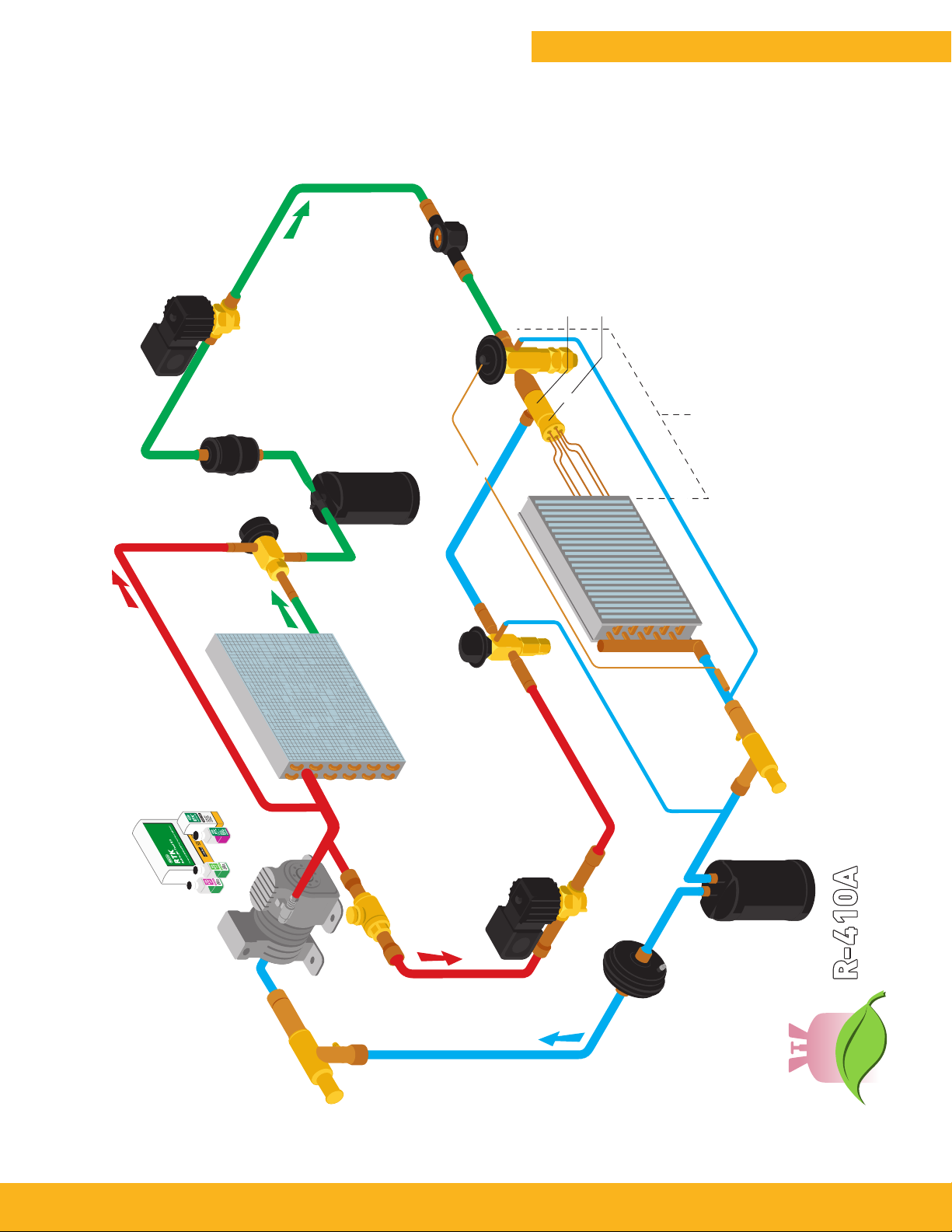
Typical Piping Diagram
Suction Line
Filter-Drier
Accumulator
*
Liquid Line
Solenoid
Valve
*
Liquid
*
Liquid Line
Filter-Drier
*
Receiver
Moisture &Liquid
Indicator
Liquid
Catalog C-1, Accumulators and Receivers / Page 3
Thermostatic
Expansion Valve
ASC Auxiliary
Side Connector
Refrigerant
Distributor
*
TEVs,
Assemblies
Saturated Liquid &
Vapor at TEV Outlet
Distributors, Tube
This schematic is for component location
only, not a typical piping recommendation.
LAC
Head
Pressure
Control
ETK/RTK
Acid Test Kit
Valve
*
Condensed
Liquid
Discharge Gas Bypassed
External Equalizer Connection
EVAPORATOR
*
HGBE
Discharge
Bypass
CONDENSER
Condenser Bypass Discharge Gas
*
EBV
Ball Valve
Valve
Hot Gas
Solenoid
*
ORIT
Evaporator Pressure
Regulating Valve
External Equalizer
Connection
Valve
*
COMPRESSOR
CROT
Crankcase
Pressure
Regulating
*
Valve
Suction Line
Models Available
*
Superheated Suction Gas
Page 4
Page 4 / Catalog C-1, Accumulators and Receivers
Steel Suction Line Accumulators
Design
The function of a suction line accumulator in a heat pump or refrigeration system
is to catch and hold any unused portion of
the system charge. The device must also
prevent liquid slugging of the compressor and excessive refrigerant dilution of
the compressor oil.
The accumulator must return refrigerant
and oil to the compressor at a sufficient
rate to maintain both system operating
efficiency and proper crankcase oil level.
To make sure these tasks are accomplished, system designers must consider
the following items:
■ A properly sized and protected oil re-
turn orifice is required to ensure positive oil (and refrigerant) return to the
compressor
■ The accumulator must have sufficient in-
ternal volume
■ The pressure drop across the accumula-
tor should be as low as possible
Oil return at a minimum flow rate is
controlled by the outlet U-tube size.
Refrigerant and oil will be returned to
the compressor by pressure drop across
the orifice metering area and the liquid
head above the orifice. Other design
requirements include safe working pressure, agency approvals and corrosion
resistance.
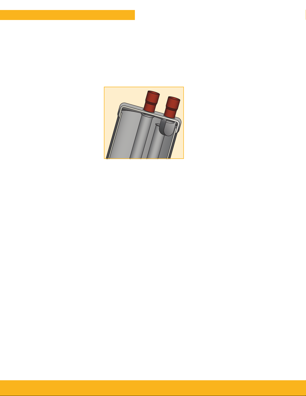
Figure 1 illustrates a typical accumulator with an inlet defector. The shape of
the deflector directs the inlet flow in a
slightly downward tangential direction.
The inlet to the U-tube is located behind
the inlet deflector to prevent liquid carryover and is bell-shaped to reduce the
sudden contraction loss of the highvelocity gas. The U-tube diameter is
selected to minimize pressure drop at
high flow rates yet provide adequate oil
return at low flow rates.
Other features include a 50 x 60 mesh
screen to protect the oil return orifice,
an anti-siphon hole and a fusible alloy
plug in the accumulator. The anti-siphon
hole located near the outlet of the U-tube
prevents liquid from siphoning into the
outlet tube and compressor during an offcycle. The fusible alloy plug is generally
a U.L. requirement since it is a safety
device to protect against excessive pressure in the event of a fire.
Figure 1
Typical accumulator with inlet deflector baffle.
Selection
Accumulator selection can be fine-tuned
for best performance. This involves the
sizing of the accumulator and the sizing
of the orifice. The controlling factor for
both types is the type of metering device
used in the system. In systems using a
fixed orifice, the accumulator holding
capacity should be about 70% of the
system charge. This provides adequate
holding capacity during operation with
blocked or fouled heat exchanger coils.
The resulting high discharge/low suction
pressure condition will result in more
liquid refrigerant in the accumulator. The
oil return orifice size should be small to
prevent excess liquid refrigerant being
returned to the compressor. For these
systems, a 0.040 inch (1.02 mm) diameter orifice is the recommended starting
point.
For systems with a thermostatic expan-
sion valve (TEV), the accumulator holding capacity should be approximately
50% of the system charge. At startup
and after defrost the bulb of the TEV is
warm. Until the valve regains control,
the accumulator plays a role in preventing liquid slugging of the compressor.
The accumulator must also contend with
off cycle refrigerant migration. At shut-
down, the accumulator is the coldest
component in the system. This results
in migration of liquid refrigerant to the
device. This type of system needs to
return the refrigerant to circulation more
quickly than the fixed orifice system.
For these systems, a 0.055 inch (1.4 mm)
diameter orifice allows quick return of
the liquid refrigerant. The recommended
sizes of the orifices can be further tested
for optimum results. Other size orifices
are possible to satisfy the characteristics
required by the system designer.
New Refrigerants
The introduction of alternative refrigerants and oils requires reviewing the
design of components within the system, including suction accumulators. As
previously stated, the accumulator is the
coldest component in the system. The
new refrigerants and oils may or may
not be fully miscible in the temperature
range the accumulator normally operates. The oil and refrigerant can separate
into oil rich and refrigerant rich layers
in the accumulator, with the refrigerant
rich layer at the bottom. The oil return
orifice would be located in the refrigerant rich layer.
The solution to this problem is to provide
active mixing of the layers in the accumulator. This is accomplished by the
shape and position of the inlet deflector
and outlet U-tube. The inlet flow stream
is directed tangentially into the liquid
layers in the bottom of the accumulator.
The resulting circulation of the liquid
past the off center U-tube forces a mixing of the oil and refrigerant layers.
Field Replacement
The accumulator should be changed
when a compressor is replaced. The
old accumulator may contain contaminants from the problem that caused the
compressor failure. There may also be
considerable oil remaining from the first
compressor if a gradual loss of refrigerant caused the failure. This amount
coupled with the oil in the replacement
compressor may create an oil overcharge
condition.
Page 5
Catalog C-1, Accumulators and Receivers / Page 5
Steel Suction Line Accumulators
U-Tube Style Accumulators – VA, PA and VPA Series
The U-tube accumulator design is a result of extensive laboratory testing of
various designs. It takes into account essential requirements such as safe holding
volume (relative to the system’s total charge), protected flow control for positive
refrigerant and oil return, and minimum pressure drop across the accumulator.
Parker offers standard accumulator models designed for application on heat pump and
refrigeration systems from 1/4 ton (.88 kW) through 28.5 tons (100.2 kW). Liquid
refrigerant holding requirements of suction accumulator may vary by application.
Features and Benefits
■ Solid copper connections (except where noted in the following tables)
■ U-tube design for maximum flow of refrigerant and minimum oil entrapment
■ Inlet flow deflector guides refrigerant toward wall for smooth tangential flow and gradual
expansion
■ Baffled U-tube entrance is positioned behind the inlet flow deflector to prevent unwanted
liquid refrigerant from entering and damaging compressor at all rated conditions
■ Metering orifice matched to system capacity which optimizes liquid refrigerant and oil
flow return back to compressor at all rated conditions
■ Protective screen and orifice assembly on U-tube protects against contaminants affecting
metering function
■ Minimum pressure drop and Maximum refrigerant flow
■ VA and VPA models are U.L. Listed for USA and Canada for 300 psig (20.7 bar) maximum
working pressure under SA5764-SKXY/SKXY7
■ PA models are U.L. Listed for USA and Canada for 355 psig (24.5 bar) maximum working
pressure under SA5764-SKXY/SKXY7
■ Powder coating surpasses 500 hour ASTM salt spray
■ Integral 430°F (221°C) fuse plugs on larger models
■ Compatible with CFC, HCFC and HFC refrigerants including R-22, R-134a, R-404A, R-407C,
R-410A, R-500, R-502 and R-507
Dimensions and Flow Data
Refer to pages 6 through 10 for dimension values and flow data.
Page 6

Page 6 / Catalog C-1, Accumulators and Receivers
Dimensions
IN
“VA” Series
“E”
OUT
“A”
“D”
“C”
“B”
“PA” and “VPA” Series
“E”
“D”
IN
OUT
“A”
“B”
“C”
Page 7

Dimensions
Catalog C-1, Accumulators and Receivers / Page 7
Catalog
Number
VA304S
Unit
Item
Number
Weight
lbs.
(KG)
1
470043 1.7 (0.8) 3 (76.0) 8-1/4 (210.0) 7-1/2 (191.0) 1/2 (12.7) 1-5/8 (41.0) 0.060 (1.5) 0.030 (0.85) 35 (1.02)
“A”
Diameter
Inches
(mm)
“B”
Overall Length
Inches
(mm)
“C””C”
Vessel Length
Inches
(mm)
“D”
Connection
Inches
(mm)
“E”
Fitting
Inches
(mm)
“F”
Oil Orifice
Inches
(mm)
Internal
Volume
Cu. Ft.
(liters)
Capacities
VA314S 470106 1.9 (0.9) 3 (76.0) 10-3/8 (264.0) 9-3/8 (238.0) 1/2 (12.7) 1-3/4 (44.0) 0.055 (1.4) 0.034 (0.96) 1.16 (39)
VA315S 470107 1.9 (0.9) 3 (76.0) 10-3/8 (264.0) 9-3/8 (238.0) 5/8 (15.9) 1-3/4 (44.0) 0.055 (1.4) 0.034 (0.96) 1.16 (39)
VA325S 470048 2.1 (1.0) 3 (76.0) 12-1/4 (311.0) 11-1/2 (292.0) 5/8 (15.9) 1-5/8 (41.0) 0.060 (1.5) 0.040 (1.13) 46 (1.36)
1
VA326S
470136 2.1 (1.0) 3 (76.0) 12-5/8 (321.0) 11-1/2 (292.0) 3/4 (19.1) 1-5/8 (41.0) 0.060 (1.5) 0.040 (1.13) 46 (1.36)
VA355S 470049 2.7 (1.2) 3 (76.0) 15-1/16 (383.0) 13-3/4 (349.0) 5/8 (15.9) 1-5/8 (41.0) 0.055 (1.4) 0.051 (1.44) 59 (1.74)
VA356S 470093 2.7 (1.2) 3 (76.0) 15-1/16 (383.0) 13-3/4 (349.0) 3/4 (19.1) 1-5/8 (41.0) 0.055 (1.4) 0.051 (1.44) 59 (1.74)
1
VA445SRD
VA446SRD
470051 4.3 (2.0) 4 (102.0) 10-3/4 (273.0) 9-15/16 (252.0) 5/8 (15.9) 2-1/2 (64.0) 0.035 (0.9) 0.072 (2.04) 83 (2.45)
1
470094 4.3 (2.0) 4 (102.0) 10-5/8 (270.0) 9-3/4 (248.0) 3/4 (19.1) 2-1/2 (64.0) 0.055 (1.4) 0.072 (2.04) 83 (2.45)
PA4065-9-5C 960119 4.3 (2.0) 4 (102.0) 9-5/8 (244.0) 8-1/2 (216.0) 5/8 (15.9) 1-3/4 (44.0) 0.055 (1.4) 0.061 (1.73) 70 (2.08)
PA4065-9-6C 960120 4.3 (2.0) 4 (102.0) 9-5/8 (244.0) 8-1/2 (216.0) 3/4 (19.1) 1-3/4 (44.0) 0.055 (1.4) 0.061 (1.73) 70 (2.08)
VA546SRD 470052 5.2 (2.4) 5 (127.0) 9-5/8 (244.0) 8-1/2 (216.0) 3/4 (19.1) 2-3/4 (70.0) 0.063 (1.6) 0.09 (2.55) 104 (3.07)
VA547SRD 470054 5.2 (2.4) 5 (127.0) 9-3/4 (248.0) 8-1/2 (216.0) 7/8 (22.2) 2-3/4 (70.0) 0.063 (1.6) 0.09 (2.55) 104 (3.07)
VA557SRD 470055 7.0 (3.2) 5 (127.0) 10-3/4 (273.0) 9-1/2 (241.0) 7/8 (22.2) 3.0 (76.0) 0.055 (1.4) 0.11 (3.11) 127 (3.75)
VA566SRD 470056 7.9 (3.6) 5 (127.0) 12-3/4 (324.0) 11-5/8 (295.0) 3/4 (19.1) 2-3/4 (70.0) 0.063 (1.6) 0.13 (3.68) 150 (4.43)
VA567SRD 470058 7.9 (3.6) 5 (127.0) 13 (330.0) 11-3/4 (298.0) 7/8 (22.2) 2-3/4 (70.0) 0.063 (1.6) 0.13 (3.68) 150 (4.43)
VA577SRD 470059 8.1 (3.7) 5 (127.0) 14-5/8 (371.0) 13-3/8 (340.0) 7/8 (22.2) 2-3/4 (70.0) 0.063 (1.6) 0.14 (3.96) 161 (4.77)
VA579SRD 470060 8.1 (3.7) 5 (127.0) 14-13/16 (376.0) 13-3/8 (340.0) 1-1/8 (28.6) 2-3/4 (70.0) 0.063 (1.6) 0.14 (3.96) 161 (4.77)
VPA5896SRD 470110 5.1 (2.3) 5 (127.0) 9-5/8 (244.0) 8-5/16 (211.0) 3/4 (19.1) 1-3/4 (44.0) 0.055 (1.4) 0.085 (2.41) 98 (2.90)
VPA5897SRD 470111 4.9 (2.2) 5 (127.0) 9-5/8 (244.0) 8-1/8 (206.0) 7/8 (22.2) 1-3/4 (44.0) 0.055 (1.4) 0.083 (2.35) 96 (2.83)
VPA58116SRD 470112 6.8 (3.1)
5 (127.0) 11-5/16 (287.0) 10 (254.0) 3/4 (19.1) 1-3/4 (44.0) 0.055 (1.4) 0.103 (2.91) 119 (3.51)
VPA58117SRD 470069 6.0 (2.7) 5 (127.0) 11-5/16 (287.0) 9-13/16 (249.0) 7/8 (22.2) 1-3/4 (44.0) 0.055 (1.4) 0.101 (2.86) 116 (3.44)
VPA58127SRD 470070 7.7 (3.5) 5 (127.0) 12-7/8 (327.0) 11-3/8 (289.0) 7/8 (22.2) 1-3/4 (44.0) 0.055 (1.4) 0.117 (3.31) 135 (3.99)
VPA58157SRD 470115 8.4 (3.8) 5 (127.0) 15-3/8 (391.0) 13-13/16 (351.0) 7/8 (22.2) 1-3/4 (44.0) 0.055 (1.4) 0.143 (4.05) 165 (4.88)
VPA58177SRD 470116 9.6 (4.4) 5 (127.0) 17-1/4 (438.0) 15-3/4 (400.0) 7/8 (22.2) 1-3/4 (44.0) 0.055 (1.4) 0.163 (4.61) 188 (5.56)
VA599SRD 470062 8.4 (3.8) 5 (127.0) 18-3/8 (467.0) 16-15/16 (430.0) 1-1/8 (28.6) 2-3/4 (70.0) 0.063 (1.6) 0.18 (5.09) 207 (6.14)
VA5911SRD 470061 8.4 (3.8) 5 (127.0) 18-7/16 (468.0) 16-15/16 (430.0) 1-3/8 (34.9) 2-3/4 (70.0) 0.063 (1.6) 0.18 (5.09) 207 (6.14)
VA6107SRD
VA6109SRD
1
470117 11.8 (5.4) 6 (152.0) 13-7/8 (352.0) 12-5/8 (321.0) 7/8 (22.2) 2-15/16 (75.0) 0.040 (1.0) 0.18 (5.09) 207 (6.14)
1
470118 11.8 (5.4) 6 (152.0) 14 (356.0) 12-5/8 (321.0) 1-1/8 (28.6) 2-15/16 (75.0) 0.040 (1.0) 0.18 (5.09) 207 (6.14)
VA6119SRD 470065 12.4 (5.6) 6 (152.0) 15-1/4 (387.0) 13-3/4 (349.0) 1-1/8 (28.6) 2-15/16 (75.0) 0.075 (1.9) 0.20 (5.66) 230 (6.82)
VA61111SRD
1
470063 12.4 (5.6) 6 (152.0) 15-1/4 (387.0) 13-3/4 (349.0) 1-3/8 (34.9) 2-15/16 (75.0) 0.060 (1.5) 0.20 (5.66) 230 (6.82)
VA61511SRD 470066 15.9 (7.2) 6 (152.0) 19-1/2 (495.0) 18 (457.0) 1-3/8 (34.9) 2-15/16 (75.0) 0.075 (1.9) 0.29 (8.21) 334 (9.89)
VA61613SRD
1
470068 16.3 (7.4) 6 (152.0) 21-7/8 (556.0) 20-1/4 (514.0) 1-5/8 (41.3) 2-15/16 (75.0) 0.060 (1.5) 0.30 (8.49) 346 (10.23)
Holding capacities stated for R-410A at 40°F (4°C).
Multiply holding capacity by 1.1 to obtain R-22 data at 40°F (4°C).
Multiply total system charge by 0.7 to obtain recommended maximum holding capacity for fixed orifice systems.
Multiply total system charge by 0.5 to obtain recommended maximum holding capacity for systems with TEVs.
Catalog numbers in bold font are available as standard wholesale offering.
1
These models have copper-plated steel connections. All other models have solid copper connections.
Holding
Ounces
(liters)
Page 8

Page 8 / Catalog C-1, Accumulators and Receivers
Flow Capacity
Catalog
Number
1
VA304S
VA314S 2.0 (7.0) 1.3 (4.6) 0.9 (3.1)
VA315S 3.0 (10.6) 2.0 (6.9) 1.3 (4.7)
VA325S 3.0 (10.6) 2.0 (6.9) 1.3 (4.7)
1
VA326S
VA355S 3.0 (10.6) 2.0 (6.9) 1.3 (4.7)
VA356S 4.0 (14.1) 2.6 (9.2) 1.8 (6.2)
1
VA445SRD
1
VA446SRD
PA4065-9-5C 3.0 (10.6) 2.4 (8.4) 1.9 (6.7)
PA4065-9-6C 3.0 (10.6) 2.5 (8.8) 2.0 (7.0)
VA546SRD 4.0 (14.1) 2.6 (9.2) 1.8 (6.2)
VA547SRD 7.3 (25.7) 4.8 (16.7) 3.2 (11.4)
VA557SRD 7.3 (25.7) 4.8 (16.7) 3.2 (11.4)
VA566SRD 4.0 (14.1) 2.6 (9.2) 1.8 (6.2)
VA567SRD 7.3 (25.7) 4.8 (16.7) 3.2 (11.4)
VA577SRD 7.3 (25.7) 4.8 (16.7) 3.2 (11.4)
VA579SRD
VPA5896SRD 4.0 (14.1) 2.6 (9.1) 1.8 (6.3)
VPA5897SRD 7.3 (25.7) 4.8 (16.7) 3.2 (11.4)
VPA58116SRD 7.5 (26.4) 5.0 (17.6) 3.4 (12.0)
VPA58117SRD 7.3 (25.7) 4.8 (16.9) 3.2 (11.3)
VPA58127SRD 6.3 (22.2) 4.5 (15.8) 3.0 (10.6)
VPA58157SRD 10.4 (36.6) 6.9 (24.3) 3.7 (13.0)
VPA58177SRD 11.2 (39.4) 7.4 (26.0) 4.9 (17.2)
VA599SRD 11.8 (41.5) 7.7 (27.0) 5.2 (18.4)
VA5911SRD 18.8 (66.1) 12.3 (43.1) 8.3 (29.3)
VA6107SRD
VA6109SRD
VA61111SRD
VA61511SRD 18.8 (66.1) 12.3 (43.1) 8.3 (29.3)
VA61613SRD
1
1
1
1
+40°F (+4°C) +20°F (-6°C) 0°F (-17°C)
2.0 (7.0) 1.3 (4.6) 0.9 (3.1)
4.0 (14.1) 2.6 (9.2) 1.8 (6.2)
3.0 (10.6) 2.0 (6.9) 1.3 (4.7)
4.0 (14.1) 2.6 (9.2) 1.8 (6.2)
11.8 (41.5) 7.7 (27.0) 5.2 (18.4)
7.3 (25.7) 4.8 (16.7) 3.2 (11.4)
11.8 (41.5) 7.7 (27.0) 5.2 (18.4)
18.8 (66.1) 12.3 (43.1) 8.3 (29.3)
28.5 (100.2) 18.6 (65.3) 12.6 (44.5)
Flow Capacity in Tons (kW)
Refrigerant 22
Factors For Other Ratings
Evaporator Temperature -20°F (-28°C) -40°F (-40°C)
X Factor 0.28 0.18
To find the capacity for -20°F (-28°C) and -40°F (-40°C) evaporator temperatures in tons, multiply the 40°F (4°C) evaporator
temperature by the X factor.
To find the minimum capacity in tons, multiply the 40°F (4°C)
rating by 0.15.
Maximum recommended tons based on pressure drop through
the accumulator equal to 1.0°F (-17°C) temperature drop.
Notes:
1. Minimum recommended tons should be no less than 15%
of recommended tons to ensure positive oil return.
2. All data based on actual tons and is not related to horsepower.
3. Minimum evaporator temperature: -40°F (4°C). Minimum
suction gas temperature through the accumulator: +10°F
(-12°C). For operating conditions not within the rating data,
please contact Parker before proceeding with installation.
Page 9

Flow Capacity
Catalog C-1, Accumulators and Receivers / Page 9
Catalog
Number
1
VA304S
VA314S 1.3 (4.5) 0.8 (2.9) 0.5 (1.9) 1.3 (4.5) 0.9 (3.0) 0.5 (1.8)
VA315S 1.9 (6.8) 1.2 (4.3) 0.8 (2.8) 1.9 (6.7) 1.3 (4.5) 0.8 (2.8)
VA325S 1.9 (6.8) 1.2 (4.3) 0.8 (2.8) 1.9 (6.7) 1.3 (4.5) 0.8 (2.8)
1
VA326S
VA355S 1.9 (6.8) 1.2 (4.3) 0.8 (2.8) 1.9 (6.7) 1.3 (4.5) 0.8 (2.8)
VA356S 2.6 (9.1) 1.6 (5.7) 1.1 (3.8) 2.5 (8.9) 1.7 (6.0) 1.0 (3.7)
VA445SRD
VA446SRD
PA4065-9-5C 2.2 (7.7) 1.8 (6.3) 1.6 (5.6) 2.5 (8.8) 1.6 (5.6) 1.4 (4.9)
PA4065-9-6C 2.2 (7.7) 1.9 (6.7) 1.7 (5.9) 2.5 (8.8) 1.7 (5.9) 1.5 (5.3)
VA546SRD 2.6 (9.1) 1.6 (5.7) 1.1 (3.8) 2.5 (8.9) 1.7 (6.0) 1.0 (3.7)
VA547SRD 4.7 (16.5) 3.0 (10.5) 2.0 (6.9) 4.6 (16.3) 3.1 (11.0) 1.9 (6.7)
VA557SRD 4.7 (16.5) 3.0 (10.5) 2.0 (6.9) 4.6 (16.3) 3.1 (11.0) 1.9 (6.7)
VA566SRD 2.6 (9.1) 1.6 (5.7) 1.1 (3.8) 2.5 (8.9) 1.7 (6.0) 1.0 (3.7)
VA567SRD 4.7 (16.5) 3.0 (10.5) 2.0 (6.9) 4.6 (16.3) 3.1 (11.0) 1.9 (6.7)
VA577SRD 4.7 (16.5) 3.0 (10.5) 2.0 (6.9) 4.6 (16.3) 3.1 (11.0) 1.9 (6.7)
VA579SRD 7.6 (26.7) 4.8 (16.9) 3.2 (11.1) 7.5 (26.4) 5.0 (17.7) 3.1 (10.9)
VPA5896SRD 2.6 (9.1) 1.6 (5.6) 1.1 (4.0) 2.5 (8.8) 1.7 (6.0) 1.0 (3.5)
VPA5897SRD 4.7 (16.5) 3.0 (10.5) 2.0 (6.9) 4.6 (16.3) 3.1 (11.0) 1.9 (6.7)
VPA58116SRD 4.7 (16.5) 3.0 (10.6) 2.0 (7.0) 4.6 (16.2) 3.1 (10.9) 1.9 (6.7)
VPA58117SRD 4.5 (15.8) 2.8 (9.8) 1.8 (6.3) 4.4 (15.5) 2.8 (9.8) 1.7 (6.0)
VPA58127SRD 4.6 (16.2) 2.9 (10.2) 1.9 (6.7) 4.5 (15.8) 2.9 (10.2) 1.8 (6.3)
VPA58157SRD 4.8 (16.9) 3.2 (11.3) 2.2 (7.7) 4.7 (16.5) 3.2 (11.3) 2.0 (7.0)
VPA58177SRD 6.6 (23.2) 4.8 (16.9) 3.2 (11.3) 7.5 (26.4) 5.0 (17.6) 3.1 (10.9)
VA599SRD 7.6 (26.7) 4.8 (16.9) 3.2 (11.1) 7.5 (26.4) 5.0 (17.7) 3.1 (10.9)
VA5911SRD 12.1 (42.6) 7.7 (27.0) 5.1 (17.8) 12.0 (42.1) 8.0 (28.2) 4.9 (17.3)
VA6107SRD
VA6109SRD
VA61111SRD
VA61511SRD 12.1 (42.6) 7.7 (27.0) 5.1 (17.8) 12.0 (42.1) 8.0 (28.2) 4.9 (17.3)
VA61613SRD
+40°F (+4°C) +20°F (-6°C) 0°F (-17°C) +40°F (+4°C) +20°F (-6°C) 0°F (-17°C)
1.3 (4.5) 0.8 (2.9) 0.5 (1.9) 1.3 (4.5) 0.9 (3.0) 0.5 (1.8)
2.6 (9.1) 1.6 (5.7) 1.1 (3.8) 2.5 (8.9) 1.7 (6.0) 1.0 (3.7)
1
1
1
1
1.9 (6.8) 1.2 (4.3) 0.8 (2.8) 1.9 (6.7) 1.3 (4.5) 0.8 (2.8)
2.6 (9.1) 1.6 (5.7) 1.1 (3.8) 2.5 (8.9) 1.7 (6.0) 1.0 (3.7)
4.7 (16.5) 3.0 (10.5) 2.0 (6.9) 4.6 (16.3) 3.1 (11.0) 1.9 (6.7)
7.6 (26.7) 4.8 (16.9) 3.2 (11.1) 7.5 (26.4) 5.0 (17.7) 3.1 (10.9)
1
12.1 (42.6) 7.7 (27.0) 5.1 (17.8) 12.0 (42.1) 8.0 (28.2) 4.9 (17.3)
1
18.4 (64.6) 11.6 (40.9) 7.7 (26.9) 18.1 (63.8) 12.2 (42.8) 7.5 (26.2)
Refrigerant 502 Refrigerant 134a
Flow Capacity in Tons (kW)
Factors For Other Ratings
Evaporator Temperature -20°F (-28°C) -40°F (-40°C)
X Factor 0.28 0.18
To find the capacity for -20°F (-28°C) and -40°F (-40°C) evaporator temperatures in tons, multiply the 40°F (4°C) evaporator
temperature by the X factor.
To find the minimum capacity in tons, multiply the 40°F (4°C)
rating by 0.15.
Maximum recommended tons based on pressure drop through
the accumulator equal to 1.0°F (-17°C) temperature drop.
Notes:
1. Minimum recommended tons should be no less than 15%
of recommended tons to ensure positive oil return.
2. All data based on actual tons and is not related to horsepower.
3. Minimum evaporator temperature: -40°F (4°C). Minimum
suction gas temperature through the accumulator: +10°F
(-12°C). For operating conditions not within the rating data,
please contact Parker before proceeding with installation.
Page 10

Page 10 / Catalog C-1, Accumulators and Receivers
Flow Capacity
Catalog
Number
1
VA304S
VA314S 1.9 (6.7) 1.2 (4.2) 0.8 (2.8) 1.4 (4.8) 0.8 (2.9) 0.6 (1.9)
VA315S 2.8 (10.0) 1.8 (6.4) 1.2 (4.2) 2.0 (7.2) 1.3 (4.4) 0.8 (2.9)
VA325S 2.8 (10.0) 1.8 (6.4) 1.2 (4.2) 2.0 (7.2) 1.3 (4.4) 0.8 (2.9)
1
VA326S
VA355S 2.8 (10.0) 1.8 (6.4) 1.2 (4.2) 2.0 (7.2) 1.3 (4.4) 0.8 (2.9)
VA356S 3.8 (13.4) 2.4 (8.5) 1.6 (5.6) 2.7 (9.6) 1.7 (5.9) 1.1 (3.9)
VA445SRD
VA446SRD
PA4065-9-5C 2.9 (10.2) 2.5 (8.8) 2.3 (8.0) 3.0 (10.6) 2.4 (8.4) 1.9 (6.7)
PA4065-9-6C 2.9 (10.2) 2.6 (9.1) 2.3 (8.0) 3.0 (10.6) 2.5 (8.8) 2.0 (7.0)
VA546SRD 3.8 (13.4) 2.4 (8.5) 1.6 (5.6) 2.7 (9.6) 1.7 (5.9) 1.1 (3.9)
VA547SRD 6.9 (24.4) 4.4 (15.5) 2.9 (10.3) 5.0 (17.5) 3.0 (10.7) 2.0 (7.1)
VA557SRD 6.9 (24.4) 4.4 (15.5) 2.9 (10.3) 5.0 (17.5) 3.0 (10.7) 2.0 (7.1)
VA566SRD 3.8 (13.4) 2.4 (8.5) 1.6 (5.6) 2.7 (9.6) 1.7 (5.9) 1.1 (3.9)
VA567SRD 6.9 (24.4) 4.4 (15.5) 2.9 (10.3) 5.0 (17.5) 3.0 (10.7) 2.0 (7.1)
VA577SRD 6.9 (24.4) 4.4 (15.5) 2.9 (10.3) 5.0 (17.5) 3.0 (10.7) 2.0 (7.1)
VA579SRD 11.2 (39.4) 7.1 (25.0) 4.7 (16.6) 8.1 (28.3) 4.9 (17.3) 3.3 (11.5)
VPA5896SRD 3.8 (13.4) 2.4 (8.4) 1.6 (5.6) 2.7 (9.5) 1.7 (6.0) 1.1 (3.9)
VPA5897SRD 6.9 (24.4) 4.4 (15.5) 2.9 (10.3) 5.0 (17.5) 3.0 (10.7) 2.0 (7.1)
VPA58116SRD 6.9 (24.3) 4.4 (15.5) 2.9 (10.2) 5.0 (17.6) 3.0 (10.6) 2.0 (7.0)
VPA58117SRD 6.5 (22.9) 4.2 (14.8) 2.5 (8.8) 4.7 (16.5) 2.8 (9.8) 1.8 (6.3)
VPA58127SRD 6.8 (23.9) 4.3 (15.1) 2.8 (9.8) 4.8 (16.9) 2.8 (9.8) 1.8 (6.3)
VPA58157SRD 7.0 (24.6) 4.6 (16.2) 3.2 (11.3) 5.2 (18.3) 3.2 (11.3) 2.2 (7.7)
VPA58177SRD 12.1 (42.6) 8.0 (28.1) 5.6 (19.7) 9.0 (31.7) 5.8 (20.4) 4.1 (14.4)
VA599SRD 11.2 (39.4) 7.1 (25.0) 4.7 (16.6) 8.1 (28.3) 4.9 (17.3) 3.3 (11.5)
VA5911SRD 17.8 (62.7) 11.3 (39.9) 7.5 (26.4) 12.8 (45.2) 7.8 (27.6) 5.2 (18.3)
VA6107SRD
VA6109SRD
VA61111SRD
VA61511SRD 17.8 (62.7) 11.3 (39.9) 7.5 (26.4) 12.8 (45.2) 7.8 (27.6) 5.2 (18.3)
VA61613SRD
+40°F (+4°C) +20°F (-6°C) 0°F (-17°C) +40°F (+4°C) +20°F (-6°C) 0°F (-17°C)
1.9 (6.7) 1.2 (4.2) 0.8 (2.8) 1.4 (4.8) 0.8 (2.9) 0.6 (1.9)
3.8 (13.4) 2.4 (8.5) 1.6 (5.6) 2.7 (9.6) 1.7 (5.9) 1.1 (3.9)
1
1
1
1
2.8 (10.0) 1.8 (6.4) 1.2 (4.2) 2.0 (7.2) 1.3 (4.4) 0.8 (2.9)
3.8 (13.4) 2.4 (8.5) 1.6 (5.6) 2.7 (9.6) 1.7 (5.9) 1.1 (3.9)
6.9 (24.4) 4.4 (15.5) 2.9 (10.3) 5.0 (17.5) 3.0 (10.7) 2.0 (7.1)
11.2 (39.4) 7.1 (25.0) 4.7 (16.6) 8.1 (28.3) 4.9 (17.3) 3.3 (11.5)
1
17.8 (62.7) 11.3 (39.9) 7.5 (26.4) 12.8 (45.2) 7.8 (27.6) 5.2 (18.3)
1
27.0 (95.1) 17.2 (60.4) 11.4 (40.1) 19.5 (68.4) 11.9 (41.8) 7.9 (27.7)
Refrigerant 407C Refrigerant 404A/507C
Flow Capacity in Tons (kW)
Factors For Other Ratings
Evaporator Temperature -20°F (-28°C) -40°F (-40°C)
X Factor 0.28 0.18
To find the capacity for -20°F (-28°C) and -40°F (-40°C) evaporator temperatures in tons, multiply the 40°F (4°C) evaporator
temperature by the X factor.
To find the minimum capacity in tons, multiply the 40°F (4°C)
rating by 0.15.
Maximum recommended tons based on pressure drop through
the accumulator equal to 1.0°F (-17°C) temperature drop.
Notes:
1. Minimum recommended tons should be no less than 15%
of recommended tons to ensure positive oil return.
2. All data based on actual tons and is not related to horsepower.
3. Minimum evaporator temperature: -40°F (4°C). Minimum
suction gas temperature through the accumulator: +10°F
(-12°C). For operating conditions not within the rating data,
please contact Parker before proceeding with installation.
Page 11

Catalog C-1, Accumulators and Receivers / Page 11
Copper Vertical, Horizontal and Stand-Pipe
Accumulators - OEM only
Parker's Vertical, Horizontal, and Stand-Pipe Copper Accumulators hold unused
system charge to prevent liquid slugging of the compressor and excessive refrigerant
dilution of the compressor oil.
Applications
■ Low temperature refrigeration and heat-pump applications
■ Residential air conditioning systems
Features and Benefits
■ Accumulators available in vertical (inlet and outlet on same end), horizontal (inlet and out-
let on opposite ends), and stand-pipe designs
■ Stand-pipe design can be made with or without an orifice to meter oil return to the compressor
■ Systems using a rotary compressor should use a stand-pipe accumulator including a
screened baffle and an oil-return orifice for maximum system performance
■ A wide variety of O.D. and volume sizes are designed to meet the unique requirements of
a system
■ Bifurcated ODF solder in a variety of sizes provide for easy installation
■ Copper Accumulator models are UL recognized for maximum working pressures listed under
SA5764-SKXY/SKXY7
1-1/8" Copper Accumulator
Maximum
Part
Number
032185-00 450 31.0 3/8 1/4 8.25 210 1.97 32.3 1.13 28.7
Rated
Pressure
PSIG bar Inlet (A) Outlet (B) Inches mm Cu. In. cm3Inches mm
Standard Nominal
Sizes (Inches)
Overall Length
(C)
Internal Volume Diameter (D)
1-3/16" Copper Accumulator
Maximum
Part
Number
056268-00 450 31.0 3/8 3/8 5 127 4.75 77.8 1.19 30.2
051639-03 450 31.0 3/8 3/8 6.5 165 4.75 77.8 1.19 30.2
056039-01 450 31.0 3/8 5/16 6.5 165 4.75 77.8 1.19 30.2
056039-02 450 31.0 5/16 5/16 6.5 165 4.75 77.8 1.19 30.2
Rated
Pressure
PSIG bar Inlet (A) Outlet (B) Inches mm Cu. In. cm3Inches mm
Standard Nominal
Sizes (Inches)
Overall Length
(C)
Internal Volume Diameter (D)
Dimensions
BA
C
1-3/8" Copper Accumulator
Maximum
Part
Number
057375-00
056380-01 450 31.0 3/8 3/8 6 152 6.86 112 1.38 35.1
Rated
Pressure
PSIG bar Inlet (A) Outlet (B) Inches mm Cu. In. cm3Inches mm
450 31.0
Standard Nominal
Sizes (Inches)
3/8 3/8 7.06 179 2.52 41.3 1.38 35.1
Overall Length
(C)
Internal Volume Diameter (D)
1-5/8" Copper Accumulator
Maximum
Part
Number
056238-01 450 31.0 5/16 1/4 4 102 5.41 88.7 1.63 41.4
056689-02 450 31.0 3/8 3/8 4 102 5.41 88.7 1.63 41.4
057337-00 450 31.0 1/2 1/2 5 127 7.29 119.5 1.63 41.4
058489-01 450 31.0 5/16 5/16 5 127 7.29 119.5 1.63 41.4
057995-00 450 31.0 3/8 3/8 5.5 140 2.59 42.4 1.63 41.4
056326-03 450 31.0 1/4 1/4 7 178 11.15 182.7 1.63 41.4
056472-01 450 31.0 3/8 3/8 8 203 12.902 211.4 1.63 41.4
056463-03 450 31.0 1/2 1/2 10 254 16.55 271.2 1.63 41.4
056463-02 450 31.0 3/8 3/8 10 254 16.55 271.2 1.63 41.4
Rated
Pressure
PSIG bar Inlet (A) Outlet (B) Inches mm Cu. In. cm3Inches mm
Standard Nominal
Sizes (Inches)
Overall Length
(C)
Internal Volume Diameter (D)
D
Page 12

Page 12 / Catalog C-1, Accumulators and Receivers
1-7/8" Copper Stand Pipe Accumulator
Maximum
Part
Number
071442-00 450 31.0 3/8 3/8 10.2 259 13.44 220.2 1.88 47.6
Rated
Pressure
PSIG bar Inlet (A) Outlet (B) Inches mm Cu. In. cm3Inches mm
Standard Nominal
Sizes (Inches)
Overall Length
(C)
Internal Volume
Diameter
(D)
2-1/4" Copper Stand Pipe Accumulator
Maximum
Part
Number
032236-00 450 31.0 1/2 0.616 8.19 208 12.63 207.0 2.25 57.2
Rated
Pressure
PSIG bar Inlet (A) Outlet (B) Inches mm Cu. In. cm3Inches mm
Standard Nominal
Sizes (Inches)
Overall Length
(C)
Internal Volume
Diameter
(D)
Dimensions
A
C
B
D
A
C
B
D
Page 13

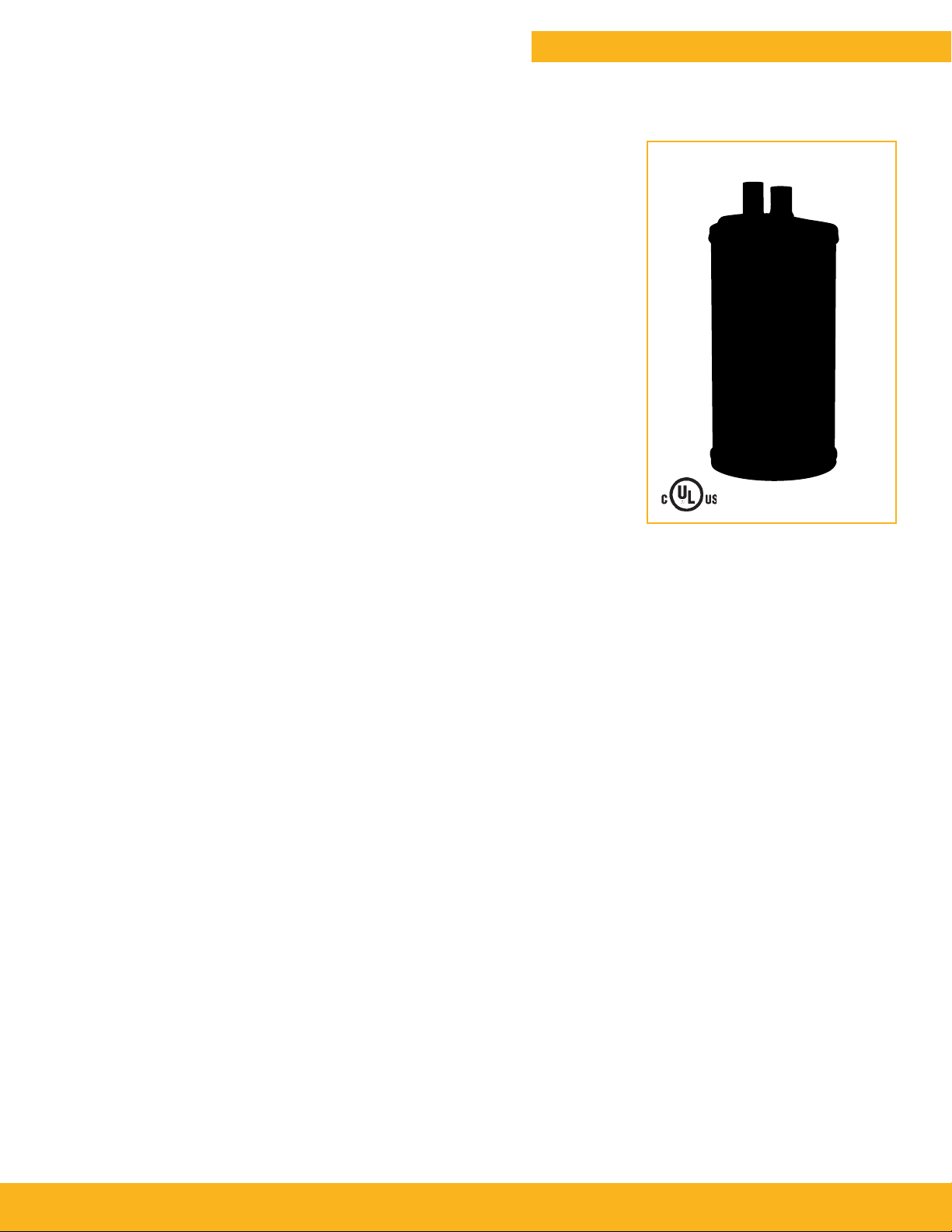
Steel Receivers
Catalog C-1, Accumulators and Receivers / Page 13
Design
The RT series receiver tanks are multifunctional in a refrigeration system. It
provides a reservoir for refrigerant during normal operation of a refrigeration
system, ensures availability of a reserve
quantity of refrigerant during periods of
high load demands and provides a place
to store the refrigerant charge during either automatic or service pump downs.
Receiver tank storage capacities are
based on 80% of the internal volume
of the tank when the temperature of the
refrigerant is 90°F (32°C) per ARI standard 495. Receiver selection should be
based on the vessels ability to hold 100%
of the total system refrigerant charge.
Four different styles of receiver connections are available: one with a sweat inlet and a rotolock outlet spud, one with
sweat by sweat connections, one with a
sweat inlet with a sweat outlet service
valve brazed onto the top closure and
one with a sweat inlet with a sweat outlet service valve brazed onto body tube.
Additionally, Parker offers vertical and
horizontal models to provide greater
flexibility in different applications.
Applications
Designed for installation in the liquid
line of any refrigeration or air conditioning application which requires a storage
vessel for liquid refrigerant either for
system pump downs or as a safeguard to
ensure that a solid column of liquid is in
the liquid line.
CAUTION: Do not exceed design pressure. Fasten receiver and piping securely
before use.
Features and Benefits
■ Available with 1/4” - 5/8” ODF sweat
solid copper connections
■ Vertical, horizontal and custom designed
models available
■ Models from 2-1/2” through 6” diameters
with maximum lengths of 35”
■ Vertical models are provided with
3 different types of connections
■ Horizontal models have sweat
connections
■ 500 psig (35 bar) maximum working
pressure
■ Compatible with CFC, HCFC, HFC
refrigerants, mineral oils, alkylbenzene
(AB), polyolester (POE) and polyalkylene
glycol (PAG) lubricants.
■ Integral 430°F (221°C) fuse plug in 5”
and 6” diameter models
■ Valve is shipped unassembled
■ PTFE gasket seal for valve
■ UL listed for USA and Canada under
SA5915-SOJV/SOJV7
■ Manufactured in ISO 9001/ISO 14001
registered facility
■ Valves can be brazed to the body or
connected via rotolock stub with
PTFE seal
■ Receivers available with or without
isolation valves
■ Powder coating surpasses 500 hour
ASTM salt spray
Page 14

Page 14 / Catalog C-1, Accumulators and Receivers
Dimensions
OUT
OUT
OUT
OUT
OUT
OUT
“A”
“A”
“C”
“C”
TYPE 1
Type 1
“B”
OUT
OUT
Type 4
TYPE 4
“B”
IN
IN
“A”
“C”
IN
“D”
TYPE 2
Type 2
IN
IN
“D” “D”
“B”
“D”
Type 5
TYPE 5
IN
OUT IN
OUT
“C” “C”
IN
“A”
“C”
OUT
OUT
TYPE 3
Type 3
“B”
Type 6
TYPE 6
IN
IN
“D”
IN
IN
“D”
“B”
“B”
Page 15

Dimensions
Catalog C-1, Accumulators and Receivers / Page 15
Type
Holding
Capacity
Catalog
Number
RT256V 469988 1/4 (6.0) Solder x 1/4 (6.0) Solder 6-3/4 (171) 2-1/2 (64) 5-7/8 (149) 2 (51) 29.4 (0.482) 1 1.1 (0.52)
RT306V-TS 470122 1/4 (6.0) Solder x 1/4 (6.0) Solder 6-3/4 (171) 3 (76) 5-7/8 (149) 2 (51) 43.2 (0.708) 1 1.6 (0.76)
RT306V-TR 469993 1/4 (6.0) Solder x 3/4 (19.0) Rotolock 6-3/4 (171) 3 (76) 5-7/8 (149) 2 (51) 43.2 (0.708) 2 1.6 (0.76)
RT308V-TR 469996 1/4 (6.0) Solder x 3/4 (19.0) Rotolock 8-3/8 (213) 3 (76) 7-1/2 (191) 2 (51) 51.9 (0.851) 2 1.9 (0.91)
RT308V-TS 470137 3/8 (10.0) Solder x 3/8 (10.0) Solder 8-3/8 (213) 3 (76) 7-1/2 (191) 2 (51) 51.9 (0.851) 1 1.9 (0.91)
RT312V-TS 470139 3/8 (10.0) Solder x 3/8 (10.0) Solder 14 (356) 3 (76) 13-1/8 (333) 2 (51) 82.9 (1.360) 1 3.1 (1.45)
RT3510V2S-KS 470123 3/8 (10.0) Solder x 1/4 (6.0) Valve 11-1/8 (283) 3-1/2 (89) 10 (254) 2 (51) 84.7 (1.389) 4 3.1
RT3510V2S 450220 3/8 (10.0) Solder x 1/4 (6.0) Solder — 3-1/2 (89) 10 (254) 2-1/2 (64) 84.7 (1.389) 5 3.1 (1.48)
RT3510V3S 469999 3/8 (10.0) Solder x 3/8 (10.0) Valve 11-1/8 (283) 3-1/2 (89) 10 (254) 2 (51) 84.7 (1.389) 4 3.1 (1.48)
RT3510V 470087 3/8 (10.0) Solder x 3/8 (10.0) Solder — 3-1/2 (89) 10 (254) 2-1/2 (64) 94.2 (1.545) 5 3.5 (1.65)
RT507V 470002 1/4 (6.0) Solder x 3/4 (19.0) Rotolock 8-5/8 (219) 5 (127) 7-3/4 (197) 2-1/2 (64) 136.5 (2.239) 3 5.1 (2.39)
RT508V3S 470000 3/8 (10.0) Solder x 3/8 (10.0) Valve — 5 (127) 8 (203) 2-1/2 (64) 126.6 (2.076) 6 4.7 (2.22)
RT510V3S 470124 3/8 (10.0) Solder x 3/8 (10.0) Valve 11-1/8 (283) 5 (127) 10 (254) 2-1/2 (64) 177.9 (2.918) 4/6 6.6 (3.12)
RT510V3S-KS 470004 3/8 (10.0) Solder x 3/8 (10.0) Valve — 5 (127) 10 (254) 2-1/2 (64) 177.9 (2.918) 5 6.6 (3.12)
RT512V 470010 3/8 (10.0) Solder x 3/4 (19.0) Rotolock 12-7/8 (327) 5 (127) 12 (305) 2-1/2 (64) 214.3 (3.515) 3 7.9 (3.76)
RT512V3S 470008 3/8 (10.0) Solder x
RT612V 470019 3/8 (10.0) Solder x 3/4 (19.0) Rotolock 12-7/8 (327) 6 (152) 12 (305) 2-1/2 (64) 298.9 (4.902) 3 11.1 (5.24)
RT612V3S-KS 470125 3/8 (10.0) Solder x 3/8 (10.0) Valve — 6 (152) 12 (305) 4 (102) 298.9 (4.902) 6 11.1 (5.24)
RT612V3S 470013 3/8 (10.0) Solder x 3/8 (10.0) Valve 13-1/8 (333) 6 (152) 12 (305) 2-1/2 (64) 298.9 (4.902) 4/5 11.1 (5.24)
RT612V4S 470089 3/8 (10.0) Solder x 1/2 (13.0) Valve 13-1/8 (333) 6 (152) 12 (305) 2-1/2 (64) 298.9 (4.902) 4 11.1 (5.24)
RT615V 470022 3/8 (10.0) Solder x 1 (25.0) Rotolock 15-7/8 (403) 6 (152) 15 (381) 2-1/2 (64) 376.7 (6.178) 3 13.9 (6.60)
RT616V3S-KS 470126 3/8 (10.0) Solder x 3/8 (10.0) Valve 17-1/8 (435) 6 (152) 16 (406) 2-1/2 (64) 416.4 (6.829) 4 15.4 (7.30)
RT616V3S 470024 3/8 (10.0) Solder x 3/8 (10.0) Solder — 6 (152) 16 (406) 2-1/2 (64) 416.4 (6.829) 5 15.4 (7.30)
RT616V4S 470025 3/8 (10.0) Solder x 1/2 (13.0) Valve 17-3/8 (441) 6 (152) 16 (406) 2-1/2 (64)
RT616V4S 470138 1/2 (13.0) Solder x 1/2 (13.0) Valve 17-3/8 (441) 6 (152) 16-1/8 (410) 2-1/2 (64) 418.4 (6.862) 4 15.5 (7.33)
RT617V4S 470026 1/2 (13.0) Solder x 1/2 (13.0) Valve — 6 (152) 17-1/8 (435) 3-3/4 (95) 480.4 (7.879) 6 17.8 (8.42)
RT618V4S-KS 470127 1/2 (13.0) Solder x 1/2 (13.0) Valve 19-3/8 (492) 6 (152) 18 (457) 2-1/2 (64) 470.0 (7.708) 4 17.4 (8.24)
RT619V 470033 1/2 (13.0) Solder x 1 (25.0) Rotolock 20 (508) 6 (152) 19 (483) 2-1/2 (64) 480.4 (7.879) 3 17.8 (8.42)
RT623V4S-KS 470128 1/2 (13.0) Solder x 1/2 (13.0) Valve 24-3/8 (619) 6 (152) 23 (584) 2-1/2 (64) 601.3 (9.861) 4 22.2 (10.54)
RT623V5S 470034 1/2 (13.0) Solder x 5/8 (16.0) Valve 24-3/8 (619) 6 (152) 23 (584) 2-1/2 (64) 601.3 (9.861) 4 22.2 (10.54)
RT627V4S 470036 1/2 (13.0) Solder x 1/2 (13.0) Valve — 6 (152) 27-1/8 (689) 3-3/4 (95) 709.1 (11.629) 6 26.2 (12.43)
RT630V5S 470038 5/8 (16.0) Solder x 5/8 (16.0) Solder — 6 (152) 30 (762) 5 (127) 784.3 (12.863) 6 29.0 (13.74)
RT634V4S
Select receiver with holding capacity equal to or greater than 90% of system charge.
Holding capacities stated for R-410A at 90°F (32°C).
Multiply holding capacity by 1.1 to obtain R-22 data at 90°F (32°C).
Catalog numbers in bold font are available as standard wholesale offering.
Item
470040 1/2 (13.0) Valve x 1/2 (13.0) Valve — 6 (152) 35 (876) 4-1/8 (105) 915.0 (15.006) 6 33.9 (16.03)
No.
Inches
(mm)
Fitting
Type
Inches
(mm)
3/4 (19.0) Rotolock 13-1/8 (333) 5 (127) 12 (305) 2-1/2 (64) 214.3 (3.515) 4 7.9 (3.76)
Fitting
Type
“A” “B” “C” “D” Cu. In. (liters) lbs. (liters)
Dimensions: Inches (mm) Internal Volume
416.4 (6.829) 4 15.4 (7.30)
(1.48)
Page 16

Page 16 / Catalog C-1, Accumulators and Receivers
OFFER OF SALE
The goods, services or work (referred to as the “Products”) offered by Parker-Hannifin Corporation, its subsidiaries, groups, divisions, and authorized distributors (“Seller”)
are offered for sale at prices indicated in the offer, or as may be established by Seller. The offer to sell the Products and acceptance of Seller’s offer by any customer (“Buyer”) is
contingent upon, and will be governed by all of the terms and conditions contained in this Offer of Sale. Buyer’s order for any Products specied in Buyer’s purchase document
or Seller’s offer, proposal or quote (“Quote”) attached to the purchase order, when communicated to Seller verbally, or in writing, shall constitute acceptance of this offer.
1. Terms and Conditions. Seller’s willingness to
offer Products for sale or accept an order for Products
is subject to the terms and conditions contained in
this Offer of Sale or any newer version of the same,
published by Seller electronically at www.parker.com/
saleterms/. Seller objects to any contrary or additional
terms or conditions of Buyer’s order or any other
document or other communication issued by Buyer.
2. Price; Payment. Prices stated on Seller’s Quote
are valid for thirty (30) days, except as explicitly
otherwise stated therein, and do not include any sales,
use, or other taxes or duties unless specically stated.
Seller reserves the right to modify prices to adjust for
any raw material price uctuations. Unless otherwise
specied by Seller, all prices are F.C.A. Seller’s facility
(INCOTERMS 2010). Payment is subject to credit approval and payment for all purchases is due thirty (30)
days from the date of invoice (or such date as may
be specied by Seller’s Credit Department). Unpaid
invoices beyond the specied payment date incur
interest at the rate of 1.5% per month or the maximum
allowable rate under applicable law.
3. Shipment; Delivery; Title and Risk of Loss. All
delivery dates are approximate. Seller is not responsible for damages resulting from any delay. Regardless
of the manner of shipment, delivery occurs and title
and risk of loss or damage pass to Buyer, upon
placement of the Products with the shipment carrier
at Seller’s facility. Unless otherwise stated, Seller
may exercise its judgment in choosing the carrier and
means of delivery. No deferment of shipment at Buyers’ request beyond the respective dates indicated will
be made except on terms that will indemnify, defend
and hold Seller harmless against all loss and additional
expense. Buyer shall be responsible for any additional
shipping charges incurred by Seller due to Buyer’s
acts or omissions.
4. Warranty. Seller warrants that the Products sold
hereunder shall be free from defects in material or
workmanship for a period of twelve (12) months from
the date of delivery or 2,000 hours of normal use,
whichever occurs rst. All prices are based upon the
exclusive limited warranty stated above, and upon the
following disclaimer: DISCLAIMER OF WARRANTY:
THIS WARRANTY IS THE SOLE AND ENTIRE WARRANTY PERTAINING TO PRODUCTS PROVIDED.
SELLER DISCLAIMS ALL OTHER WARRANTIES,
EXPRESS AND IMPLIED, INCLUDING DESIGN,
MERCHANTABILITY AND FITNESS FOR A PARTICULAR PURPOSE.
5. Claims; Commencement of Actions. Buyer shall
promptly inspect all Products upon receipt. No claims
for shortages will be allowed unless reported to the
Seller within ten (10) days of delivery. No other claims
against Seller will be allowed unless asserted in writing within thirty (30) days after delivery. Buyer shall
notify Seller of any alleged breach of warranty within
thirty (30) days after the date the defect is or should
have been discovered by Buyer. Any claim or action
against Seller based upon breach of contract or any
other theory, including tort, negligence, or otherwise
must be commenced within twelve (12) months from
the date of the alleged breach or other alleged event,
without regard to the date of discovery.
6. LIMITATION OF LIABILITY. IN THE EVENT OF
A BREACH OF WARRANTY, SELLER WILL, AT ITS
OPTION, REPAIR OR REPLACE A DEFECTIVE PRODUCT, OR REFUND THE PURCHASE PRICE WITHIN
A REASONABLE PERIOD OF TIME. IN NO EVENT
IS SELLER LIABLE FOR ANY SPECIAL, INDIRECT,
INCIDENTAL OR CONSEQUENTIAL DAMAGES
ARISING OUT OF, OR AS THE RESULT OF, THE
SALE, DELIVERY, NON-DELIVERY, SERVICING,
USE OR LOSS OF USE OF THE PRODUCTS OR
ANY PART THEREOF, OR FOR ANY CHARGES OR
EXPENSES OF ANY NATURE INCURRED WITHOUT
SELLER’S WRITTEN CONSENT, WHETHER BASED
IN CONTRACT, TORT OR OTHER LEGAL THEORY.
IN NO EVENT SHALL SELLER’S LIABILITY UNDER
ANY CLAIM MADE BY BUYER EXCEED THE PURCHASE PRICE OF THE PRODUCTS.
7. User Responsibility. The user, through its own
analysis and testing, is solely responsible for making
the nal selection of the system and Product and assuring that all performance, endurance, maintenance,
safety and warning requirements of the application
are met. The user must analyze all aspects of the
application and follow applicable industry standards
and Product information. If Seller provides Product
or system options based upon data or specications provided by the user, the user is responsible for
determining that such data and specications are suitable and sufcient for all applications and reasonably
foreseeable uses of the Products or systems.
8. Loss to Buyer’s Property. Any designs, tools,
patterns, materials, drawings, condential information
or equipment furnished by Buyer or any other items
which become Buyer’s property, will be considered
obsolete and may be destroyed by Seller after two (2)
consecutive years have elapsed without Buyer ordering
the items manufactured using such property. Seller
shall not be responsible for any loss or damage to such
property while it is in Seller’s possession or control.
9. Special Tooling. A tooling charge may be imposed
for any special tooling, including without limitation, dies, xtures, molds and patterns, acquired to
manufacture Products. Such special tooling shall be
and remain Seller’s property notwithstanding payment
of any charges by Buyer. In no event will Buyer acquire
any interest in apparatus belonging to Seller which
is utilized in the manufacture of the Products, even
if such apparatus has been specially converted or
adapted for such manufacture and notwithstanding
any charges paid by Buyer. Unless otherwise agreed,
Seller has the right to alter, discard or otherwise dispose of any special tooling or other property in its sole
discretion at any time.
10. Buyer’s Obligation; Rights of Seller. To secure
payment of all sums due or otherwise, Seller retains a
security interest in all Products delivered to Buyer and
this agreement is deemed to be a Security Agreement under the Uniform Commercial Code. Buyer
authorizes Seller as its attorney to execute and le on
Buyer’s behalf all documents Seller deems necessary
to perfect its security interest.
11. Improper Use and Indemnity. Buyer shall
indemnify, defend, and hold Seller harmless from any
losses, claims, liabilities, damages, lawsuits, judgments and costs (including attorney fees and defense
costs), whether for personal injury, property damage,
patent, trademark or copyright infringement or any
other claim, brought by or incurred by Buyer, Buyer’s
employees, or any other person, arising out of: (a)
improper selection, application, design, specication
or other misuse of Products purchased by Buyer from
Seller; (b) any act or omission, negligent or otherwise,
of Buyer; (c) Seller’s use of patterns, plans, drawings,
or specications furnished by Buyer to manufacture
Products; or (d) Buyer’s failure to comply with these
terms and conditions. Seller shall not indemnify Buyer
under any circumstance except as otherwise provided.
12. Cancellations and Changes. Buyer may not
cancel or modify or cancel any order for any reason,
except with Seller’s written consent and upon terms
that will indemnify, defend and hold Seller harmless
against all direct, incidental and consequential loss or
damage. Seller may change Product features, specications, designs and availability.
13. Limitation on Assignment. Buyer may not
assign its rights or obligations under this agreement
without the prior written consent of Seller.
14. Force Majeure. Seller does not assume the risk
and is not liable for delay or failure to perform any of
Seller’s obligations by reason of events or circumstances beyond its reasonable control (hereinafter
“Events of Force Majeure”). Events of Force Majeure
shall include without limitation: accidents, strikes or
labor disputes, acts of any government or government
agency, acts of nature, delays or failures in delivery
from carriers or suppliers, shortages of materials, or
any other cause beyond Seller’s reasonable control.
15. Waiver and Severability. Failure to enforce any
provision of this agreement will not invalidate that provision; nor will any such failure prejudice Seller’s right
to enforce that provision in the future. Invalidation of
any provision of this agreement by legislation or other
rule of law shall not invalidate any other provision
herein. The remaining provisions of this agreement will
remain in full force and effect.
16. Termination. Seller may terminate this agreement
for any reason and at any time by giving Buyer thirty
(30) days prior written notice. Seller may immediately
terminate this agreement, in writing, if Buyer: (a)
breaches any provision of this agreement (b) appoints
a trustee, receiver or custodian for all or any part of
Buyer’s property (c) les a petition for relief in bankruptcy on its own behalf, or one if led by a third party
(d) makes an assignment for the benet of creditors; or
(e) dissolves its business or liquidates all or a majority
of its assets.
17. Governing Law. This agreement and the sale and
delivery of all Products are deemed to have taken place
in, and shall be governed and construed in accordance
with, the laws of the State of Ohio, as applicable to
contracts executed and wholly performed therein and
without regard to conicts of laws principles. Buyer
irrevocably agrees and consents to the exclusive jurisdiction and venue of the courts of Cuyahoga County,
Ohio with respect to any dispute, controversy or claim
arising out of or relating to this agreement.
18. Indemnity for Infringement of Intellectual
Property Rights. Seller is not liable for infringement
of any patents, trademarks, copyrights, trade dress,
trade secrets or similar rights except as provided in
this Section. Seller will defend and indemnify Buyer
against allegations of infringement of U.S. patents, U.S.
trademarks, copyrights, trade dress and trade secrets
(“Intellectual Property Rights”). Seller will defend at
its expense and will pay the cost of any settlement or
damages awarded in an action brought against Buyer
based on an allegation that a Product sold pursuant
to this agreement infringes the Intellectual Property
Rights of a third party. Seller’s obligation to defend and
indemnify Buyer is contingent on Buyer notifying Seller
within ten (10) days after Buyer becomes aware of
such allegations of infringement, and Seller having sole
control over the defense of any allegations or actions
including all negotiations for settlement or compromise. If a Product is subject to a claim that it infringes
the Intellectual Property Rights of a third party, Seller
may, at its sole expense and option, procure for Buyer
the right to continue using the Product, replace or
modify the Product so as to make it noninfringing, or
offer to accept return of the Product and refund the
purchase price less a reasonable allowance for depreciation. Notwithstanding the foregoing, Seller is not
liable for claims of infringement based on information
provided by Buyer, or directed to Products delivered
hereunder for which the designs are specied in whole
or part by Buyer, or infringements resulting from the
modication, combination or use in a system of any
Product sold hereunder. The foregoing provisions
of this Section constitute Seller’s sole and exclusive
liability and Buyer’s sole and exclusive remedy for
infringement of Intellectual Property Rights.
19. Entire Agreement. This agreement contains the
entire agreement between the Buyer and Seller and
constitutes the nal, complete and exclusive expression of the terms of sale. All prior or contemporaneous
written or oral agreements or negotiations with respect
to the subject matter are herein merged. The terms
contained herein may not be modied unless in writing
and signed by an authorized representative of Seller.
20. Compliance with Laws. Buyer agrees to comply
with all applicable laws, regulations, and industry and
professional standards of care, including those of the
United Kingdom, the United States of America, and
the country or countries in which Buyer may operate,
including without limitation the U. K. Bribery Act,
the U.S. Foreign Corrupt Practices Act (“FCPA”), the
U.S. Anti-Kickback Act (“Anti-Kickback Act”) and the
U.S. Food Drug and Cosmetic Act (“FDCA”),each as
currently amended, and the rules and regulations promulgated by the U.S. Food and Drug Administration
(“FDA”), and agrees to indemnify and hold harmless
Seller from the consequences of any violation of such
provisions by Buyer, its employees or agents. Buyer
acknowledges that it is familiar with the provisions
of the U. K. Bribery Act, the FCPA, the FDA, and the
Anti-Kickback Act, and certies that Buyer will adhere
to the requirements thereof. In particular, Buyer
represents and agrees that Buyer will not make any
payment or give anything of value, directly or indirectly
to any governmental ofcial, any foreign political party
or ofcial thereof, any candidate for foreign political
ofce, or any commercial entity or person, for the purpose of inuencing such person to purchase Products
or otherwise benet the business of Seller.
Page 17

Parker Hannin Corporation
A/C & Refrigeration Aftermarket
206 Lange Drive, Washington, MO 63090 USA
phone 800 742 2681 • fax 800 241 2872
www.parker.com/coolparts
Catalog C-1 / 52016 © 2016 Parker Hannin Corporation
 Loading...