

Page 1
p/n 88-020292-01 A
Automation
E-AC Drive
Hardware Installation
Guide
Effective: April 9, 2002
Page 2
User Information
!!
WARNING
E Series products are used to control electrical and mechanical
components of motion control systems. You should test your motion
system for safety under all potential conditions. Failure to do so can result
in damage to equipment and/or serious injury to personnel.
E Series products and the information in this user guide are the proprietary property of Parker Hannifin Corporation or its licensers, and may
not be copied, disclosed, or used for any purpose not expressly authorized by the owner thereof.
Since Parker Hannifin constantly strives to improve all of its products, we reserve the right to change this user guide and software and
hardware mentioned therein at any time without notice.
In no event will the provider of the equipment be liable for any incidental, consequential, or special damages of any kind or nature
whatsoever, including but not limited to lost profits arising from or in any way connected with the use of the equipment or this user guide.
© 2002 Parker Hannifin Corporation
All Rights Reserved
Technical Assistance
North America and Asia:
Compumotor Division of Parker Hannifin
5500 Business Park Drive
Rohnert Park, CA 94928
Telephone: (800) 358-9070 or (707) 584-7558
Fax: (707) 584-3793
FaxBack: (800) 936-6939 or (707) 586-8586
e-mail: tech_help@cmotor.com
Internet: http://www.compumotor.com
Automation
Contact your local automation technology center (ATC) or distributor, or ...
Europe (non-German speaking):
Parker Digiplan
21 Balena Close
Poole, Dorset
England BH17 7DX
Telephone: +44 (0)1202 69 9000
Fax: +44 (0)1202 69 5750
Germany, Austria, Switzerland:
HAUSER Elektronik GmbH
Postfach: 77607-1720
Robert-Bosch-Str. 22
D-77656 Offenburg
Telephone: +49 (0)781 509-0
Fax: +49 (0)781 509-176
Technical Support Email
tech_help@cmotor.com
Page 3

Table of Contents
Chapter 1 – Introduction................................................................................................................................ 5
E-AC Drive – Description .................................................................................................................... 6
E-AC Drive – Compatible Motors .........................................................................................................7
Chapter 2 – Installation.................................................................................................................................. 9
What You Should Have (ship kit) ........................................................................................................10
Precautions ....................................................................................................................................... 10
Installation Overview ......................................................................................................................... 10
Automatic Test ....................................................................................................................................12
Installation ......................................................................................................................................... 14
ELECT A MOTOR ......................................................................................................................14
1 – S
2 – CONNECT THE MOTOR TO THE DRIVE – WIRING...............................................................................18
3 – SET DIP SWITCHES .................................................................................................................. 20
4 – CONNECT A CONTROLLER – INPUTS & OUTPUTS .............................................................................22
5 – M
OUNT THE DRIVE .....................................................................................................................25
6 – MOUNT THE MOTOR ....................................................................................................................26
7 – CONNECT THE MOTOR TO THE LOAD – COUPLERS ...........................................................................28
8 – CONNECT AC POWER ................................................................................................................29
9 – TEST THE INSTALLATION ...............................................................................................................30
Chapter 3 – Troubleshooting........................................................................................................................31
Troubleshooting Basics ......................................................................................................................32
Diagnostic LEDs................................................................................................................................ 32
Protective Circuits ..............................................................................................................................32
OVERTEMPERATURE PROTECTION ........................................................................................................32
SHORT CIRCUIT PROTECTION .............................................................................................................33
Automatic Test ....................................................................................................................................33
Anti-Resonance Disable.....................................................................................................................33
Technical Support ..............................................................................................................................33
Product Return Procedure ................................................................................................................ 34
Appendix A – Using Non-Compumotor Motors .........................................................................................35
Appendix B – Regulatory Compliance: UL and CE....................................................................................41
Index.............................................................................................................................................................. 47
E-AC Drive Hardware Installation Guide
3
Page 4

4
E-AC Drive Hardware Installation Guide
Page 5

CHAPTER ONE
Introduction
1
• E-AC Drive Description
• Compumotor Products
E-AC Drive Hardware Installation Guide
IN THIS CHAPTER
Chapter 1 – Introduction
5
Page 6
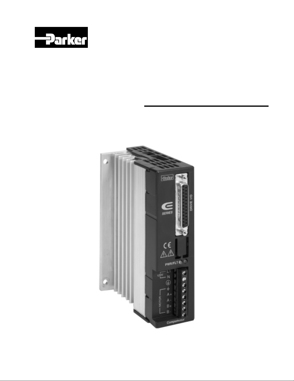
E-AC DRIVE – DESCRIPTION
C
r
e
or
or
C
s
p
ses
l
C
s
r
o
e
C
r
The E-AC Drive is a microstepping drive that runs two-phase step motors.
It operates directly from 120VAC power; no separate DC power supply or
transformer is required.
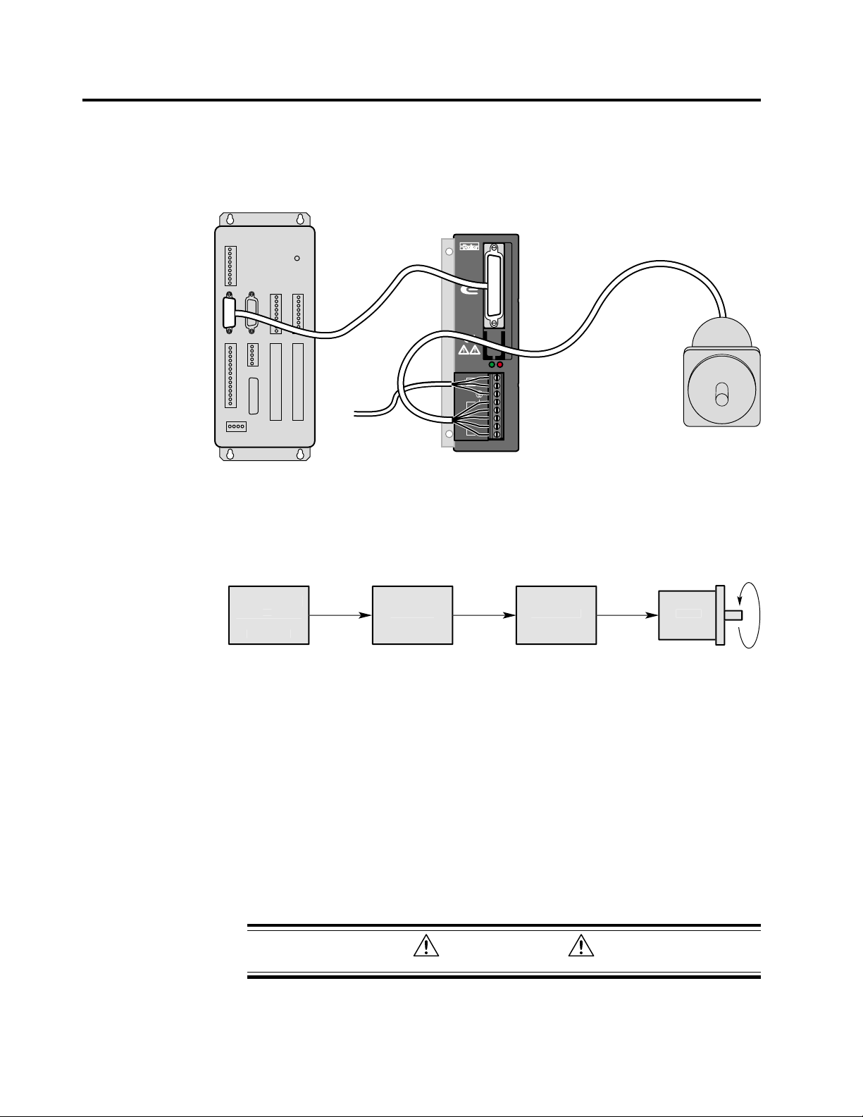
A typical system is shown below.
L1
N
A +
A -
MOTOR
B +
B -
Compumotor
DRIVE I/O
Motor
Controller
To AC
Power Source
SERIES
PWR/FLT
120V
E-AC Drive
System Components
The controller sends step and direction signals to the drive. For each step
pulse it receives, the drive will commutate the motor to increment rotor
position. This is shown in the next drawing.
Host Compute
r
Programmabl
ontrolle
High Leve
ommand
ontrolle
Pul
Ste
E-AC Driv
Mot
urrent
Mot
Block Diagram of E-AC Drive System
The host computer or programmable controller may or may not be necessary, depending upon the controller’s capabilities.
The motor can be wired in series or parallel; the amount of current the
drive sends to the motor is set by DIP switches.
DIP SWITCHES
DIP switches are located on top of the E-AC Drive, accessible through an
opening in the top of the cover. During the installation procedure, the
user sets these DIP switches to configure the drive for motor current,
resolution, waveform, and other functions.
CAUTION
Remove power before changing DIP switches
6
E-AC Drive Hardware Installation Guide Chapter 1 – Introduction
Page 7

INPUTS & OUTPUTS
All communications with the controller take place through the
E-AC Drive’s 25-pin D-connector. Available inputs and outputs are:
• Step Input
• Direction Input
• Shutdown Input
• Fault Output
• Reset Input
ANTI-RESONANCE
All step motors are subject to resonance, and to ringing after quick transient moves. The E-AC Drive has an anti-resonance circuit. This is a
general purpose damping circuit that provides aggressive and effective
damping. Anti-resonance can be disabled with a DIP switch.
E-AC DRIVE – COMPATIBLE MOTORS
Compumotor offers a wide range of motors that are compatible with the
E-AC Drive. See Chapter 2 – Installation for recommended motors.
COMPUMOTOR FAMILY OF PRODUCTS
The E-AC Drive is compatible with Compumotor’s broad range of
microstepper controllers (single-axis and multi-axis) and motion control
products.
E-AC Drive Hardware Installation Guide
Chapter 1 – Introduction
7
Page 8

8
E-AC Drive Hardware Installation Guide Chapter 1 – Introduction
Page 9

CHAPTER TWO
Installation
2
• Product Ship Kit
• Quick T est
• Motor Selection and Wiring
• Drive Configuration – DIP Switches and I/O
• Mounting the Drive and Motor; Attaching the Load
• Connecting AC Power
• Testing the Installation
E-AC Drive Hardware Installation Guide
IN THIS CHAPTER
Chapter 2 – Installation
9
Page 10

WHAT YOU SHOULD HAVE
Inspect your shipment carefully. You should have received one or more of
the following:
Part Part Number
E-AC Drive E-AC
E-AC Drive Quick Reference Guide 88-020290-01
You may have ordered a motor from one of the following families of
Compumotor motors:
OS Motors
VS Motors
PRECAUTIONS
To prevent injuries to personnel and damage to equipment, observe the
following guidelines:
• Never probe the drive. Hazardous voltages are present within the drive.
• Never open the drive. Opening the drive will void the warranty.
• Never increase the current setting to a value greater than that specified for
the motor you are using. Excessive current may cause motor overheating
and failure.
• Always remove AC power before changing or reconfiguring DIP switches.
(
SHIP KIT
)
INSTALLATION OVERVIEW
Topics in this chapter are arranged to lead you through the installation
process in a step–by–step manner. Complete each step before proceeding
to the next.
The order of topics in the installation procedure is:
• Quick Test
• Motor selection: specifications, speed/torque curves and dimensions
• Motor wiring—series vs. parallel
• DIP switch configuration
• Controller connections and 25 pin D-connector input/output schematic
• Drive mounting
• Motor mounting
• Connecting the load
• Connecting AC power
• Testing the installation
10
E-AC Drive Hardware Installation Guide Chapter 2 – Installation
Page 11
INSTALLATION PROCEDURE
11
23
21
17
16
15
14
RESET+
RESET
FLT C
FLT E
SD
SD +
DIR
DIR +
STEP
STEP +
In the following installation procedure, we assume you are using a
Compumotor motor with your E-AC Drive. If you are using a nonCompumotor motor, consult Appendix A – Using Non-Compumotor Motors
for information you may need during the following installation steps.
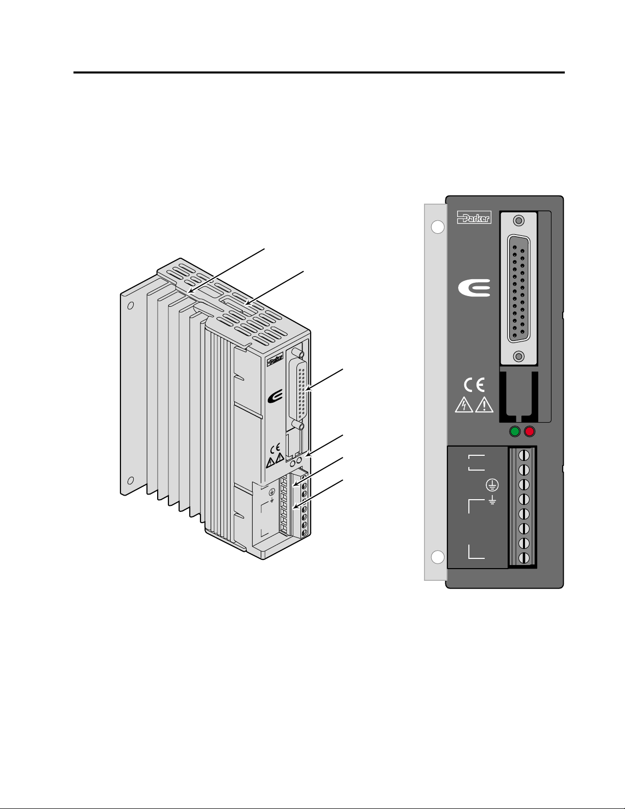
The next drawing shows locations and names of the various connectors,
switches and LEDs that you will encounter during the installation procedure.
Heatsink
DIP Switches
RESET+
RESET
FLT C
FLT E
SD
–
SD +
DIR
–
DIR +
STEP
STEP +
11
–
23
9
21
17
16
15
2
–
14
1
SERIES
DRIVE I/ O
I/O Connections
SERIES
Status LEDs
AC Power
PWR/FLT
V
N
120
A +
A -
MOTOR
B +
B -
otor
m
pu
om
C
Motor Power
PWR/FLT
120V
A +
MOTOR
B +
L1
N
A -
B -
Compumotor
Component Locations
E-AC Drive Hardware Installation Guide
Chapter 2 – Installation
11
Page 12
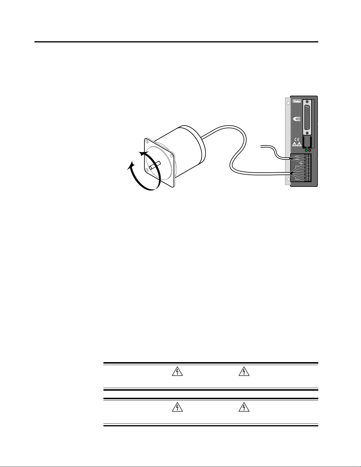
AUTOMATIC TEST
Follow this procedure to have your E-AC Drive perform its automatic test
function. Once you set DIP switches, connect the motor, and connect AC
power, the automatic test will begin—the motor shaft will turn at one
revolution per second in an alternating mode until you remove power.
This will verify that the drive, motor, and motor cable work properly as a
system.
Alternating
Shaft Rotation
Motor
Automatic Test Setup
This is a bench top procedure—as the drawing shows, you can perform it
before you connect a controller, mount the drive, or mount the motor. Full
installation instructions follow this Automatic Test section.
1. SET DIP SWITCHES FOR Motor Current
Two 8-position DIP switches are located on top of the E-AC Drive.
NOTE: if you are testing a drive that has already been configured for an
application, make note of the original DIP switch settings.
Set DIP switches SW2-#4 — SW2-#8 for the current for your motor,
according to the table. (For non-Compumotor motors, see Appendix A.)
To AC
Power Source
SERIES
PWR/FLT
L1
120V
N
A +
A -
MOTOR
B +
B -
Compumotor
E-AC Drive
DRIVE I/O
12
2. SET DIP SWITCHES FOR THE A utomatic Test Function
Set DIP switch SW1-#1 to the on position. This selects the automatic test
function.
3. CONNECT THE MOTOR
Connect your motor cable to the drive’s MOTOR terminals. Motor wiring
instructions are presented later in this chapter. (For non-Compumotor
motors, see Appendix A.) Always observe the following two warnings:
WARNING
POWER MUST BE OFF when you connect or disconnect the motor connector. Lethal
voltages are present on the screw terminals!
WARNING
You must ground the motor case. Large potentials can develop at the motor case that can
create a lethal shock hazard if the motor case is not grounded.
E-AC Drive Hardware Installation Guide Chapter 2 – Installation
Page 13
Default Position:
Drive ships from factory
with all DIP switches in
the OFF position.
Edge of
Circuit Board
Auto Test
1 rps for 2 revs in each
direction until disabled
Disabled
Enabled
1
off
on
Resolution
25,000
50,800
50,000
36,000
25,600
25,400
21,600
20,000
18,000
12,800
10,000
5,000
2,000
1,000
400
200
200 & 400 not affected by
waveform settings
Waveform
Auto Standby
Remove power before
changing DIP switches
SW1
12345678 12345678
4
2
off
on
off
on
off
on
off
on
off
on
off
on
off
on
off
on
Pure sine
-4% 3
-6% 3
-8% 3
5
3
off
off
off
off
off
off
off
off
on
off
off
on
on
off
off
on
off
off
on
off
on
on
off
on
off
on
off
off
on
off
off
on
on
off
on
on
on
on
off
on
on
off
on
on
on
on
on
on
76
off
rd
harmonic
rd
harmonic
rd
harmonic
Full Current
50% Current Reduction
on
off
off
on
off
on
on
8
off
on
1
off
on
off
on
off
on
Disabled
Enabled
SW2
off
54
off
off
off
off
off
off
off
off
on
on
on
on
on
on
on
on
off
off
off
off
off
off
off
off
on
on
on
on
on
on
on
on on
off
off
off
off
on
off
on
off
off
on
off
on
on
on
on
on
off
off
off
off
on
off
on
off
off
on
off
on
on
on
on
on
off
off
off
off
on
off
on
off
off
on
off
on
on
on
on
on
off
off
off
off
on
off
on
off
off
on
off
on
on
on
on
off
off
off
off
off
off
off
off
off
off
off
off
off
off
off
off
on
on
on
on
on
on
on
on
on
on
on
on
on
on
on
32
on
< 32 mH (all VS, OS motors)
off
32 – 64 mH
off
> 64 mH
on
> 64 mH
on
Edge of
Circuit Board
876
(amps)
Current
0.02
off
0.13
on
0.24
off
0.35
on
off
on
off
on
off
on
off
on
off
on
off
on
off
on
off
on
off
on
off
on
off
on
off
on
off
on
off
on
Select a setting based on
motor inductance (in mH).
Series = S
0.46
Parallel = P
0.58
0.69
0.80
0.91
1.03
VS12BS, VS13BS
1.14
1.25
1.36
1.48
1.59
1.70
OS2HBS
1.82
OS21BS
1.93
VS12BP, VS13BP
2.04
VS22BS, VS23BS
2.15
2.27
VS21BS
2.38
OS22BS
2.49
2.60
2.72
2.83
2.94
3.05
VS31BS
3.16
VS32BS
3.28
3.39
OS2HBP VS2xBP, VS3xBP
3.50
OS21BP, OS22BP
Gain
Anti-Resonance
NOTE: This drawing is duplicated in
4. CONNECT AC POWER
The E-AC Drive does not have an ON/OFF switch. When you connect
power, the automatic test will begin—the drive will turn on and the motor
will start turning. Therefore, before you apply power to the E-AC Drive:
• Properly secure the motor.
• Do not attach a load to the motor shaft.
To apply power, connect one end of your power cable to the drive’s 120V
and terminals. Connect the other end to a grounded 120VAC power
source. (Further instructions are presented later in this chapter.)
5. OBSERVE THE AUTOMATIC TEST
Your E-AC Drive should now be running in the automatic test mode.
• The motor shaft should rotate at approximately one revolution per second
(1 rps) in an alternating mode, until you remove power.
• LED Operation – observe the LEDs on the front panel:
6. STOP THE AUTOMATIC TEST
Disconnect power to stop the motor. Set DIP SW1-#1 to off. (Return DIP
switches of previously configured drives to original settings, if desired.)
E-AC Drive Hardware Installation Guide
Installation – Step 3: DIP Switches
PWR LED (power; green) should illuminate
FLT LED (fault; red) should be off
Chapter 2 – Installation
, later in this chapter.
13
Page 14
INSTALLATION
00
0
00
0
0
84
OS
e
q
(
)
(
)
OS
e
q
(
)
OS
e
(
)
0
3040
50
0
8
35
01020
3040
50
0
0
80
0
35
9
56
0
3040
50
8.56.70
01020
3040
50
200
0
1.05
1.40
8001000
5.607.01
e
)
(
)
e
)
q
(
)
(
)
e
)
(
)
e
)
q
(
)
(
)
e
q
(
)
e
e
q
(
)
(
)
00
300
The procedures in the rest of this chapter will lead you through the steps
required to permanently install your E-AC Drive and motor.
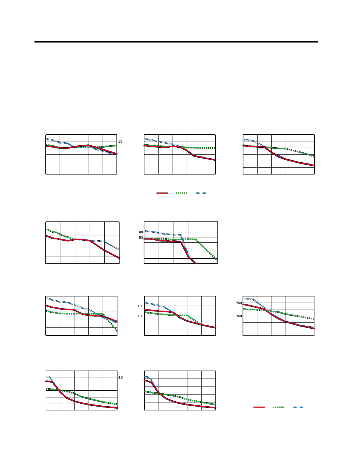
1 – SELECT A MOTOR
Speed/Torque curves, specifications, and motor dimensions for
Compumotor motors are shown below.
SPEED/TORQUE CURVES
2HB/E-AC Driv
60
50
40
30
Torque (oz-in)
20
10
0
0 1020304050
Speed (RPS)
21B/E-AC Driv
12
Torque
.35
.28
.21
.14
.07
0
1
oz-in
80
Nm
ue
60
or
40
20
0
0 1020304050
Speed (RPS)
.
.7
.56
.42
.28
.14
0
24
Torque
2
oz-in
160
Nm
ue
120
or
80
40
0
0 1020304050
22B/E-AC Driv
Speed (RPS)
1.68
1.40
1.12
.84
.56
.28
0
Torque (Nm)
VS12B/E-AC Driv
60
50
40
30
Torque (oz-in)
20
10
0
0102
Speed (RPM
VS21B/E-AC Driv
100
80
60
40
Torque (oz-in)
20
0
0102
Speed (RPM
VS31B/E-AC Driv
600
500
400
300
Torque (oz-in)
200
100
0
0 1020304050
Speed (RPM)
.
.2
.21
.14
.07
.2
.14
0
3.5
2.8
2.1
1.4
.70
0
Series
Parallel
VS13B/E-AC Driv
7
Torque
oz-in
Nm
ue
40
or
30
20
10
Speed (RPM
VS22B/E-AC Driv
Torque
oz-in
Nm
ue
or
50
0
Speed (RPM
VS32B/E-AC Driv
Torque (Nm)
oz-in
600
ue
or
400
200
0
0 1020304050
Speed (RPM)
Full Step
.7
.35
0
4.20
2.80
1.40
0
.
.4
.
.28
.21
.14
.07
Torque
Nm
VS23B/E-AC Driv
Torque
oz-in
2
Nm
ue
or
100
50
0
0 1020304050
Speed (RPM)
Torque
Nm
Series
Parallel
Full Step
2.10
1.75
1.40
1.05
.70
.35
0
Torque (Nm)
14
E-AC Drive Hardware Installation Guide Chapter 2 – Installation
Page 15

MOTOR SPECIFICATIONS
OS Motors
Size 23 Frame
Parameters Units OS2HB OS21B OS22B
Static torque oz-in 61.35 126.5 238
Rotor inertia oz-in
Drive Current Series 1.76 (1.24) 1.88 (1.33) 2.38 (1.68)
(Apk)(Arms) Parallel 3.25 (2.48) 3.76 (2.66) 4.76 (3.36)
Phase Inductance Series 8.6 12 16.6
(mH) Parallel 2.2 3 4.2
Detent Tor que oz-in 2.5 4.0 7.0
Bearings
Information
Thrust Load lb 13 13 13
Radial Load lb 20 20 20
End Play in 0.001 0.001 0.001
(Reversing load (mm) (0.025) (0.025) (0.025)
equal to 1 lb)
Radial Play in 0.0008 0.0008 0.0008
(Per 0.5 lb load) (mm) (0.02) (0.02) (0.02)
Motor Weight lb 1 1.5 2.5
Certifications UL recognized Pending Pending Pending
(Nm) (0.43) (0.84) (1.68)
2
(kg-cm2) (0.07) (0.12) (0.25)
(N-m) (0.02) (0.03) (0.05)
(kg) (5.9) (5.9) (5.9)
(kg) (9.1) (9.1) (9.1)
(kg) (0.5) (0.7) (1.1)
CE (LVD) Yes Yes Yes
CE (EMC & LVD) No No No
0.39 0.66 1.39
VS Motors
Size 17 Frame Size 23 Frame Size 34 Frame
Parameters Units VS12B VS13B VS21B VS22B VS23B VS31B VS32B
Static torque oz-in 55.27 72.8 115.5 194.5 334.5 551.8 1269.67
Rotor inertia oz-in
Drive Current Series 1.00 (0.71) 1.01(0.71) 2.26 (1.6) 2.01 (1.42) 2.01 (1.42) 3.0 (2.12) 3.13 (2.21)
(Apk)(Arms) Parallel 2.00 (1.42) 2.02 (1.43) 4.52 (3.2) 4.02 (2.84) 4.02 (2.84) 6.0 (4.24) 6.26 (4.42)
Phase Inductance Series 12.8 11.2 5.0 12.0 15.4 15.8 25
(mH) Parallel (3.2) (2.8) (1.2) (3.0) (3.8) 4.0 6.25
Detent Tor que oz-in 2.5 4.0 7.0 8.8 18.0 27.0 50
Bearings
Information
Thrust Load lb 11.0 11.0 17.6 17.6 17.6 35.3 35.3
Radial Load lb 7.7 7.7 15.0 15.0 15.0 30.9 30.9
End Play in 0.003 0.003 0.003 0.003 0.003 0.0032 0.0032
(with 2.2 lbs axial (mm) (0.075) (0.075) (0.075) (0.075) (0.075) (0.080) (0.080)
load)
Radial Play (with in 0.001 0.001 0.001 0.001 0.001 0.0008 0.0008
1.1 lb radial load) (mm) (0.025) (0.025) (0.025) (0.025) (0.025) (0.020) (0.020)
Motor Weight lb 0.55 0.77 1.03 1.54 2.2 3.86 6.18
(Nm) (0.39) (0.51) (0.82) (1.37) (2.36) (3.90) (8.97)
2
2
(kg-cm
) (0.054) (0.068) (0.12) (0.3) (0.48) (1.4) (2.7)
(N-m) (0.02) (0.03) (0.05) (0.06) (0.13) (0.19) (0.35)
(kg) (5) (5) (8) (8) (8) (16) (16)
(kg) (3.5) (3.5) (6.8) (6.8) (6.8) (14) (14)
(kg) (0.25) (0.35) (0.47) (0.7) (1.0) (1.75) (2.8)
0.3 0.37 0.66 1.64 2.62 7.65 4.8
E-AC Drive Hardware Installation Guide
Chapter 2 – Installation
15
Page 16

MOTOR DIMENSIONS
Dimensions in inches (mm)
0.200 (5.08) dia (4)
(66.68) BC
on 2.625
1.86
2.25
(47.2)
(57.2)
1.502
(38.15)
1.498
(38.05)
Model
OS2HA, OS2HB
OS21A, OS21B
OS22A, OS22B
OS Motors – Frame Size 23 – Dimensions
45°
A
1.60 (40.7)
2.06 (52.4)
3.10 (78.8)
0.2500
0.2495
Shaft Dia
0.81(20.6)
(6.350)
(6.337)
B
2.44 (62.0)
2.90 (73.7)
3.94 (100.1)
Flexible boot
may be bent as
(5.08)
shown. Nominal
height 1.0 (25.4).
1.0
(25.4)
Ø 0.02500
.75 ± 0.04
Optional rear
shaft
0.25
C
(6.4)
0.20
0.055(1.40)
A
C
For flying leads (FLY) – 13.5 (343) min.
For 10 ft cable (L10) – 120.0 (3048)
+.0000
-.0005
1.06
(26.9)
2.44
(62.0)
2X 2–56 UNC–2B
.170 MIN.
ON A Ø 1.812 B.C.
.84
(21.34)
1.50
(38.1)
B
RE/RC Encoder (optional)
VS Motors – Frame Size 17 – Dimensions
16
E-AC Drive Hardware Installation Guide Chapter 2 – Installation
Page 17

VS Motors – Frame Size 23 – Dimensions
VS Motors – Frame Size 34 – Dimensions
E-AC Drive Hardware Installation Guide
Chapter 2 – Installation
17
Page 18

2 – CONNECT THE MOTOR TO THE DRIVE – WIRING
Most Compumotor motor windings—phase A and phase B—are bifilar
windings made from double-stranded copper wire. Each phase has two
half-windings, which can be wired together in series or parallel.
These two alternatives—series and parallel—produce different speed/
torque characteristics, affect the motor’s current rating, and alter the
motor’s operating temperature. They are explained below.
GROUND THE MOTOR CASE
The motor case must be grounded, for safety purposes. On pre-cabled
Compumotor motors, one end of the cable shield is permanently wired to
the motor case; you should connect the other end to on the drive’s
motor connector. Inside the drive, connects directly to the ground pin
on the AC power terminals.
PRECAUTIONS
Follow these precautions when you wire the motor connector.
1. Turn off power to the drive before connecting or disconnecting the motor
leads.
2. Verify that no wire whiskers short out motor connections.
3. Do not apply power to the drive when the motor is not connected.
4. Never connect anything other than the motor to the motor terminals.
5. After wiring the motor connector, perform the Automatic Test, to verify that
the connector is wired correctly.
CONNECTING THE MOTOR: SERIES WIRING
For series motor current, connect a Compumotor motor as shown in the
following diagram.
OS Motors;
VS Motors
Compumotor Motor
Phase A
Windings
PM
Phase B
Windings
Shield is internally connected
to the motor’s case
(flying lead):
Red/White
Yellow/White
Red
Yellow
Orange
Black
Orange/White
Black/White
Shield
Motor Connector – Wired for SERIES Motor Current
Be sure to insulate the center tap connections; these are the wires shown
joined together in the drawing above, but not connected to the drive.
The operating temperature of a motor connected in series will be lower
than that of a motor connected in parallel. Therefore, you should operate
your motor in series, if your application permits. Typically, series connections work well in high torque/low speed applications.
VS Motors
(with cable):
Yellow
Blue
Red
Black
White
Green
Orange
Brown
A +
A -
B +
B -
18
E-AC Drive Hardware Installation Guide Chapter 2 – Installation
Page 19

CONNECTING THE MOTOR: PARALLEL WIRING
For parallel motor current, connect a Compumotor motor as shown in the
following diagram.
Compumotor Motor
Phase A
Windings
PM
Phase B
Windings
Shield
VS Motors
(flying lead):
Red
Yellow/White
Red/White
Yellow
Orange
Black/White
Orange/White
Black
OS Motors;
VS Motors
(with cable):
Red
Blue
Yellow
Black
White
Brown
Orange
Green
Shield is internally
connected to the
motor’s case
A+
AB+
B-
Motor Connector – Wired for PARALLEL Motor Current
At higher speeds, a motor connected in parallel will produce more torque
than the same motor connected in series. However, the operating temperature of the motor in parallel will be much higher.
If you operate your motor in parallel, you must measure motor temperature under actual operating conditions. If the motor exceeds its maximum
case temperature, reduce the duty cycle, or use automatic standby to
reduce current at rest, or use forced air cooling to limit motor heating.
Compumotor motors have maximum case temperature of 100°C (212°F).
CAUTION
High current in parallel connected motors may cause motor overheating. You may need to
reduce the duty cycle to 50% to decrease motor temperature, or use automatic standby.
SERIES VERSUS PARALLEL – SUMMARY
The following list summarizes the points discussed above.
1. Examine the speed/torque curves for your motor.
2. Use series connection, if possible. (The motor will run cooler.)
3. Use parallel connection, if you need more torque than series connection
provides. (Typically, at higher speeds.)
4. Parallel connection will cause the motor to run hotter, so measure motor
temperature under operating conditions.
5. If necessary, reduce duty cycle, use automatic standby or use forced air
cooling to keep motor temperature within acceptable limits.
E-AC Drive Hardware Installation Guide
Chapter 2 – Installation
19
Page 20

3 – SET DIP SWITCHES
Two 8-position DIP switches are located on top of the E-AC Drive. Configure these DIP switches for your motor and application. The table below
summarizes switch settings.
Default Position:
Drive ships from factory
with all DIP switches in
the OFF position.
Edge of
Circuit Board
Auto Test
1 rps for 2 revs in each
direction until disabled
Disabled
Enabled
1
off
on
Resolution
25,000
50,800
50,000
36,000
25,600
25,400
21,600
20,000
18,000
12,800
10,000
5,000
2,000
1,000
400
200
200 & 400 not affected by
waveform settings
Waveform
Auto Standby
Remove power before
changing DIP switches
SW1
12345678 12345678
4
2
off
on
off
on
off
on
off
on
off
on
off
on
off
on
off
on
Pure sine
-4% 3
-6% 3
-8% 3
5
3
off
off
off
off
off
off
off
off
on
off
off
on
on
off
off
on
off
off
on
off
on
on
off
on
off
on
off
off
on
off
off
on
on
off
on
on
on
on
off
on
on
off
on
on
on
on
on
on
76
off
rd
harmonic
rd
harmonic
rd
harmonic
Full Current
50% Current Reduction
on
off
off
on
off
on
on
8
off
on
1
off
on
off
off
off
on
on
off
on
on
Disabled
Enabled
SW2
off
54
off
off
off
off
off
off
off
off
on
on
on
on
on
on
on
on
off
off
off
off
off
off
off
off
on
on
on
on
on
on
on
on on
off
off
off
off
on
off
on
off
off
on
off
on
on
on
on
on
off
off
off
off
on
off
on
off
off
on
off
on
on
on
on
on
off
off
off
off
on
off
on
off
off
on
off
on
on
on
on
on
off
off
off
off
on
off
on
off
off
on
off
on
on
on
on
off
off
off
off
off
off
off
off
off
off
off
off
off
off
off
off
on
on
on
on
on
on
on
on
on
on
on
on
on
on
on
32
on
< 32 mH (all VS, OS motors)
32 – 64 mH
> 64 mH
> 64 mH
Edge of
Circuit Board
876 (amps)
off
on
off
on
off
on
off
on
off
on
off
on
off
on
off
on
off
on
off
on
off
on
off
on
off
on
off
on
off
on
off
on
Current
0.02
0.13
0.24
0.35
0.46
0.58
0.69
0.80
0.91
1.03
1.14
1.25
1.36
1.48
1.59
1.70
1.82
1.93
2.04
2.15
2.27
2.38
2.49
2.60
2.72
2.83
2.94
3.05
3.16
3.28
3.39
3.50
Select a setting based on
motor inductance (in mH).
Series = S
Parallel = P
VS12BS, VS13BS
OS2HBS
OS21BS
VS12BP, VS13BP
VS22BS, VS23BS
VS21BS
OS22BS
VS31BS
VS32BS
OS2HBP VS2xBP, VS3xBP
OS21BP, OS22BP
Gain
Anti-Resonance
20
NOTE: This drawing is duplicated in
Quick Test
, earlier in this chapter.
DIP Switch Location and Settings
DEFAULT SETTINGS
The factory default position is off for all switches. For the drive to operate
correctly, you must set the DIP switches for your application.
MOTOR CURRENT
Set DIP switches SW2-#4 — SW2-#8 for motor current. Verify that your
connector wiring (series or parallel) and motor current rating match the
current you set with these five switches.
E-AC Drive Hardware Installation Guide Chapter 2 – Installation
Page 21

DRIVE RESOLUTION
Set DIP switches SW1-#2 — SW1-#5 for drive resolution. There are sixteen settings, which range from 200 to 50,800 steps per revolution. The
default setting is 25,000 steps per revolution.
Be sure to set your controller to the same resolution as your E-AC Drive.
If the controller resolution and drive resolution do not match, commanded
accelerations and velocities will not be properly scaled.
WAVEFORM
Set SW1-#6 and SW1-#7 to select a current waveform. There are four
choices: one is a pure sine wave; the other three reduce the current
waveform’s 3rd harmonic by 4%, 6%, or 8%. In most applications, the
default setting (both switches off = -4% 3rd harmonic) provides the best
performance.
AUTOMATIC TEST
DIP switch SW1-#1 enables or disables the Automatic Test function. For
more information, see the Automatic Test section earlier in this chapter.
AUTOMATIC STANDBY
SW1-#8 should be off if you do not use automatic standby. Turn this
switch on to use automatic standby.
The automatic standby function allows the motor to cool when it is not
moving. Automatic standby reduces motor current by 50% if the drive
does not receive a step pulse for one second. Full current is restored upon
the first step pulse that the drive receives. Be aware that reduced current
results in reduced holding torque.
If you use the position maintenance feature of 6K or 6000 Series controllers, we recommend that you do not use automatic standby.
ANTI-RESONANCE DISABLE
SW1-#1 should be on for the anti-resonance circuit to be enabled. Normally, you will want anti-resonance enabled; therefore, this switch should
be on. If you must disable anti-resonance, turn this switch off.
CURRENT LOOP GAIN
Set SW2-#2 and SW2-#3 according to your motor’s small-signal inductance, in millihenries. The table shows the small-signal inductance range
that corresponds to each of the four settings.
Small-signal inductance is the value read on an ordinary inductance
bridge or meter.
NOTE: These two switches should be off for all Compumotor VS and OS
motors, or for any motor whose inductance is less than 32 mH.
E-AC Drive Hardware Installation Guide
Chapter 2 – Installation
21
Page 22

4 – CONNECT A CONTROLLER – INPUTS & OUTPUTS
Connect your controller cable to the DRIVE I/O connector, a 25 pin Dconnector on the front of the drive. The cable that comes with Compumotor controllers is prewired for compatibility with the E-AC Drive—you
can plug the cable directly into the E-AC Drive’s DRIVE I/O connector.
SERIES
PWR/FLT
L1
120V
N
A +
A -
MOTOR
B +
B -
Compumotor
Controller
E-AC Drive
Connecting a Compumotor Controller
If you make your own cable, or use a non-Compumotor controller, consult the drawing below when you wire your cable and connector.
Step+
Step–
Direction+
Direction–
Shutdown+
Shutdown–
Fault– (E)
Fault+ (C)
Reset–
Reset+
1
2
14
3
15
4
16
5
17
6
18
7
19
8
20
9
21
10
22
11
23
12
24
13
25
243Ω
243Ω
681Ω
681Ω
E-AC Drive – Internal Connections
HCPL2631
HCPL2631
ILD213
ILD223
ILD213
DRIVE I/O
22
Drive I/O Connector
Descriptions of each function on the 25 pin D-connector follow.
STEP INPUT
For every step pulse it receives on its step input, the drive will commutate
the motor to increment rotor position. To send a step pulse to the drive,
apply a positive voltage to STEP+ with respect to STEP–. The drive registers the pulse on the rising edge.
E-AC Drive Hardware Installation Guide Chapter 2 – Installation
Page 23

The input is optically isolated. You can drive the input differentially, or
from a single-ended source.
Step input specifications are:
Input Current: 6.5 mA minimum
15 mA maximum
Input Voltage: 3.5V minimum (min. required for on or high signal)
5.2V maximum*
Step Pulse: 200 nanosecond minimum pulse width
200 nanosecond minimum off time
2 MHz maximum pulse rate
Optically Isolated: Yes
*As a custom product, Compumotor can modify drive for higher input voltage
DIRECTION INPUT
While a positive voltage is applied to DIRECTION+ with respect to DIRECTION–, the drive will commutate the motor in the clockwise (positive)
direction as it receives step pulses on its step input.
While zero voltage (or a negative voltage) is applied to DIRECTION+ with
respect to DIRECTION–, the drive will commutate the motor in the counterclockwise (negative) direction as it receives step pulses.
The input is optically isolated. You can drive the input differentially, or
from a single-ended source.
Direction input specifications are:
Input Current: 6.5 mA minimum
15 mA maximum
Input Voltage: 3.5V minimum (min. required for on or high signal)
5.2V maximum*
Optically Isolated: Yes
Direction Change: Direction input may change polarity coincident with
first step pulse.
*As a custom product, Compumotor can modify drive for higher input voltage
SHUTDOWN INPUT
You can use the shutdown input to shutdown, or disable, the E-AC Drive.
To activate shutdown, apply a positive voltage to SHUTDOWN+ with respect
to SHUTDOWN– when the motor is not moving. During shutdown, the drive
turns off current to the motor. The current stays off as long as the voltage
is maintained on the shutdown input.
When you remove the voltage on the input, shutdown ends. The drive
restores current to the motor, in the same phase relationship that existed
before shutdown was invoked.
The shutdown input may also be differentially driven. Specifications are:
Input Current: 2.5 mA minimum
30 mA maximum
Input Voltage: 3.5V minimum (min. required for on or high signal)
13V maximum
5V maximum reverse voltage
Active Level: While voltage is applied, current to motor is shut down.
When voltage is removed, normal operations resume.
Time: 250 nanosecond minimum width
Optically Isolated: Yes
E-AC Drive Hardware Installation Guide
Chapter 2 – Installation
23
Page 24

FAUL T OUTPUT
The E-AC Drive can signal, through its fault output, that it has detected a
fault. Internally, the terminals FAULT+ (C) and FAULT- (E) connect to the
open collector and open emitter, respectively, of an optically isolated
transistor. The transistor acts like a switch: it conducts when the drive is
functioning normally; it does not conduct when any of the following
conditions exist.
• No power is applied to the drive
• AC line voltage is too low (less than 95VAC)
• Drive temperature is higher than 55°C (131°F)
• Drive detects a short circuit in motor or motor cable
Fault output specifications are:
VCE: 30VDC
V
CESAT
Collector Current: 40 mA minimum
Dissipation: 40 mW maximum
Optically Isolated: Yes
: 1 VDC
RESET INPUT
The reset input provides a means for you to reset the E-AC Drive, without
actually cycling power. To activate the reset input, apply a positive voltage
to RESET+ with respect to RESET– when the motor is not moving. The reset
will not be complete until 0.7 seconds after the voltage is removed. A reset
has the same effect on the drive as cycling power:
• DIP switch settings are loaded into the drive for configuration.
• Existing faults are cleared.
• Current to the motor is turned off while voltage is applied to the reset input.
• After voltage is removed from the reset input, the drive’s soft start procedure
will ramp current up to the startup state. The motor will move to the nearest
pole position.
• After voltage is removed from the reset input, there will be a 0.7 second
delay before reset is complete, and normal operations can continue.
Reset input specifications are:
Input Current: 2.5 mA minimum
30 mA maximum
Input Voltage: 3.5V minimum (min. required for on or high signal)
13V maximum
5V maximum reverse voltage
Reset Voltage Pulse: 250 nanosecond minimum pulse width
Active Level: While voltage is applied, reset occurs.
When voltage is removed, normal operations resume.
Reset Delay: 0.7 second delay until reset is complete, after voltage is
removed from input.
Optically Isolated: Yes
24
E-AC Drive Hardware Installation Guide Chapter 2 – Installation
Page 25

5 – MOUNT THE DRIVE
Dimensions of the E-AC Drive are shown below.
4.34
(110.1)
4.10
(104.1)
0.43
(10.8)
0.18
(4.6)
1.89
(48.1)
1.59
(40.5)
Dimensions in inches (mm)
Dimensions – E-AC Drive
ENVIRONMENTAL CONSIDERATIONS
TEMPERATURE SPECIFICATIONS
Maximum Ambient Temperature: 50°C (122°F)
Minimum Ambient Temperature: 0°C(32°F)
Overtemperature Shutdown Fault: 55°C (131°F)
The E-AC Drive has an internal temperature sensor, located near the
heatsink. If the sensor reaches 55°C (131°F), it will trigger an overtemperature fault, and the drive will shut down.
5.35
(135.9)
2x clearance for
#8 or M4 mounting screws
4.500
(114.3)
SERIES
PWR/FLT
120V
MOTOR
Compumotor
DRIVE I/ O
L1
N
A +
A -
B +
B -
FAN COOLING
Operating the E-AC Drive in high ambient temperatures may require fan
cooling to keep the drive from shutting down due to an overtemperature
fault.
HUMIDITY
Keep the relative humidity below 95%, non-condensing.
LIQUIDS
Do not allow liquids or fluids to come into contact with the E-AC Drive or
its cables.
AIRBORNE CONTAMINANTS
Particulate contaminants, especially electrically conductive material such
E-AC Drive Hardware Installation Guide
Chapter 2 – Installation
25
Page 26

as metal shavings or grinding dust, can damage the E-AC Drive and
motor. Do not allow contaminants to come into contact with the drive or
motor.
PANEL LAYOUT
Follow these minimum spacing and clearance requirements when you
mount multiple E-AC Drives.
2.39
(60.7)
Minimum
1.00
(25.4)
Minimum
Clearance
Panel Layout Dimensions
6 – MOUNT THE MOTOR
Use flange bolts to mount rotary step motors. The pilot, or centering flange
on the motor’s front face, should fit snugly in the pilot hole.
SERIES
120V
0.50
(12.7)
Minimum
Clearance
PWR/FLT
L1
N
A +
A -
MOTOR
B +
B -
Compumotor
DRIVE I/ O
SERIES
PWR/FLT
L1
120V
N
A +
A -
MOTOR
B +
B -
Compumotor
Dimensions in
inches (millimeters)
DRIVE I/ O
0.25
(6.4)
Minimum
Clearance
1.00
(25.4)
Minimum
Clearance
26
Do not use a foot-mount or cradle configuration, because the motor’s
torque is not evenly distributed around the motor case. When a foot
mount is used, for example, any radial load on the motor shaft is multiplied by a much longer lever arm.
Step Motors can produce very high torques and accelerations. If the
mounting is inadequate, this combination of high torque/high acceleration can shear shafts and mounting hardware. Because of shock and
vibration that high accelerations can produce, you may need heavier
hardware than for static loads of the same magnitude.
Under certain move profiles, the motor can produce low-frequency vibra-
E-AC Drive Hardware Installation Guide Chapter 2 – Installation
Page 27

tions in the mounting structure that can cause fatigue in structural
members. A mechanical engineer should check the machine design to
ensure that the mounting structure is adequate.
WARNING
Improper motor mounting can jeopardize personal safety, and
compromise system performance.
For Compumotor motor dimensions, see Select a Motor earlier in this
chapter.
MOTOR TEMPERATURE & COOLING
The motor’s face flange is used not only for mounting; it is also a heatsink.
Mount the face flange to a large thermal mass, such as a thick steel or
aluminum plate, which should be unpainted, clean, and flat. Heat will be
conducted from inside the motor, through the face flange, and dissipated
in the thermal mass. This is the best way to cool the motor. You can also
use a fan to blow air across the motor for increased cooling, if conduction
through the flange does not provide enough cooling.
MOTOR MODIFICATIONS
Modifying or machining the motor shaft will void the motor warranty.
Contact a Compumotor Applications Engineer (800-358-9070) about shaft
modifications as a custom product.
EXTENDING MOTOR CABLES
If you need to extend Compumotor motor cables beyond the standard
10 feet (3 m), consult the table below for recommended wire sizes. Cables
longer than 50 feet (15 m) may degrade system performance. Do not
extend cables beyond 200 feet (61 m).
Max. Current Less than 100 ft. (30 m) 100 – 200 ft. (30 – 60 m)
Motor Type (amps) Size: AWG mm
OS2HBS 1.70 22 0.34 20 0.50
OS2HBP 3.39 20 0.50 18 0.75
OS21BS 1.82 22 0.34 20 0.50
OS21BP 3.50 20 0.50 18 0.75
OS22BS 2.38 22 0.34 20 0.50
OS22BP 3.50 20 0.50 18 0.75
VS12BS 1.03 22 0.34 20 0.50
VS12BP 2.04 22 0.34 20 0.50
VS13BS 1.03 22 0.34 20 0.50
VS13BP 2.04 22 0.34 20 0.50
VS21BS 2.27 22 0.34 20 0.50
VS21BP 3.50 20 0.50 18 0.75
VS22BS 2.04 22 0.34 20 0.50
VS22BP 3.50 20 0.50 18 0.75
VS23BS 2.04 22 0.34 20 0.50
VS23BP 3.50 20 0.50 18 0.75
VS31BS 3.05 22 0.34 20 0.50
VS31BP 3.50 20 0.50 18 0.75
VS32BS 3.16 22 0.34 20 0.50
VS32BP 3.50 20 0.50 18 0.75
S: Series Configuration P: Parallel Configuration Rated current in wire sizes shown may result in a maximum
temperature rise of 10°C (18°F) above ambient.
2
AWG mm
2
E-AC Drive Hardware Installation Guide
Chapter 2 – Installation
27
Page 28

7 – CONNECT THE MOTOR TO THE LOAD – COUPLERS
Align the motor shaft and load as accurately as possible. In most applications, some misalignment is unavoidable, due to tolerance buildups in
components. However, excessive misalignment may degrade your system’s
performance. The three misalignment conditions, which can exist in any
combination, are illustrated and described below.
Aligned
Angular Misalignment
End Float
Parallel Misalignment
Combined Parallel & Angular Misalignment
Misalignment Condition
• Angular Misalignment: The center lines of two shafts intersect at an angle
other than zero degrees.
• Parallel Misalignment: The offset of two mating shaft center lines, although
the center lines remain parallel to each other.
• End Float: A change in the relative distance between the ends of two shafts.
The type of misalignment in your system will affect your choice of coupler.
SINGLE-FLEX COUPLING
Use a single-flex coupling when you have angular misalignment only.
Because a single-flex coupling is like a hinge, one and only one of the
shafts must be free to move in the radial direction without constraint. Do
not use a double-flex coupling in this situation: it will allow too much
freedom and the shaft will rotate eccentrically, which will cause large
vibrations and catastrophic failure. Do not use a single-flex coupling
with a parallel misalignment: this will bend the shafts, causing excessive bearing loads and premature failure.
DOUBLE-FLEX COUPLING
Use a double-flex coupling whenever two shafts are joined with parallel
misalignment, or a combination of angular and parallel misalignment (the
most common situation).
Single-flex and double-flex couplings may or may not accept end play,
depending on their design.
28
RIGID COUPLING
Rigid couplings are generally not recommended, because they cannot
compensate for any misalignment. They should be used only if the motor
or load is on some form of floating mounts that allow for alignment compensation. Rigid couplings can also be used when the load is supported
entirely by the motor’s bearings. A small mirror connected to a motor
shaft is an example of such an application.
COUPLING MANUFACTURERS
HUCO ROCOM CORP. HELI-CAL
70 Mitchell Blvd, Suite 201 5957 Engineer Drive P.O. Box1069
San Rafael, CA 94903 Huntington Beach, CA 92649 Santa Maria, CA 93456
(415) 492-0278 (714) 891-9922 (805) 928-3851
E-AC Drive Hardware Installation Guide Chapter 2 – Installation
Page 29

8 – CONNECT AC POWER
At this point in your installation procedure, you should have mounted
your drive and motor, coupled the motor to the load, and connected the
controller and motor cables to the drive.
The E-AC Drive does not have an on/off switch. When you apply power to
the drive, the drive will turn on. Therefore, before you apply power, verify
the following:
• Motor should be properly secured
• Motor cable should be connected to drive
• Drive should be properly mounted
• Controller cable should be connected to drive
• Controller cable should not be in close physical proximity to motor cable
APPLY POWER
To apply power, connect one end of your power cable to the drive’s L1, N
and
terminals.
95 – 132VAC,
50 – 60 Hz,
Single phase
L1
External Fuses:
N
Are not required for AC mains with
Line and Neutral designations.
For AC mains without Line and
Neutral designations:
1. Fuse both sides of the AC mains,
as shown at right.
2. Use 125VAC Time Delay, 10 amp,
type RK5 or better fuses.
95 – 132VAC
Fuses
L1
N
AC Input Connections
Connect the other end of your power cable to a grounded 120VAC power
source that meets the following specifications:
Specifications – AC Power Input
Input Power: 120VAC nominal
95VAC minimum
132VAC maximum
50 – 60 Hz
Inrush Current: 22.2 amps (peak) maximum
Fuses: No user serviceable fuses
Grounding: You must provide a proper AC power ground
Transformer: Not required for 120VAC operation; to size step-
down transformer, use Volt-Amp rating (see the
following table)
WARNING
The motor case and drive are grounded through the drive’s terminal.
You must provide a proper AC power ground for safety purposes.
E-AC Drive Hardware Installation Guide
Chapter 2 – Installation
29
Page 30

PEAK POWER RATINGS
The amount of power the E-AC Drive requires from your AC power source
depends upon the motor you use, whether you wire the motor in series or
parallel, and upon your specific application. The next table shows peak
power requirements. Power required for your application may be less.
Motor Type Current Cabinet Peak Motor Peak Shaft Peak Total Volt-Amp
OS2HBS 1.70 22.0 22 39 83 151
OS2HBP 3.39 32.0 76 82 190 314
OS21BS 1.82 24.0 30 65 119 205
OS21BP 3.50 55.0 86 129 270 432
OS22BS 2.38 18.0 41 87 146 247
OS22BP 3.50 29.0 93 161 283 451
VS12BS 1.02 17.0 29 32 78 141
VS12BP 2.04 24.0 87 33 144 266
VS13BS 1.02 18.0 25 38 81 147
VS13BP 2.04 39.0 93 32 164 280
VS21BS 2.27 18.0 60 100 178 300
VS21BP 3.50 37.0 105 137 279 438
VS22BS 2.04 13.0 46 93 152 258
VS22BP 3.50 36.0 95 149 280 452
VS23BS 2.04 14.0 39 113 166 281
VS23BP 3.50 24.0 99 202 325 531
VS31BS 3.05 19.0 45 135 199 339
VS32BS 3.16 22.0 57 121 200 334
S: Series Configuration P: Parallel Configuration
(Amps) Loss (W) Loss (W) Power (W) Power (W) Rating (VA)
9 – TEST THE INSTALLATION
System installation should be complete at this point. Perform the test
procedure below to verify that your system is functioning properly.
In the test procedure, you will command single revolution moves in the
clockwise and counterclockwise direction. If your mechanics do not
permit such moves, choose a move that allows you to easily verify correct
system response.
30
TEST PROCEDURE
1. Apply 120VAC power. The green LED labeled PWR should illuminate.
2. Command a slow move of one revolution in the clockwise direction. Verify
that the motor turns as commanded.
3. Command a slow move of one revolution in the counterclockwise direction.
Verify that the motor turns as commanded.
4. Test the shutdown input. With the motor stopped, activate the input. The
motor will have no torque when shutdown is activated. You should be able
to turn the motor manually (if your mechanics permit).
Successful completion of this procedure will verify that your controller
and motor are correctly connected to the E-AC Drive, and that the drive is
functioning properly.
If the test is unsuccessful, proceed to Chapter 3 Troubleshooting for
problem identification and solution procedures.
E-AC Drive Hardware Installation Guide Chapter 2 – Installation
Page 31

CHAPTER THREE
Troubleshooting
3
• Troubleshooting Basics
• Diagnostic LEDs
• Protective Circuits
• Automatic T est
• Anti-Resonance Disable
• Product Return Procedure
E-AC Drive Hardware Installation Guide
IN THIS CHAPTER
Chapter 3 – Troubleshooting
31
Page 32

TROUBLESHOOTING BASICS
When your system does not function properly (or as you expect it to
operate), the first thing that you must do is identify and isolate the problem. When you have accomplished this, you can effectively begin to
resolve the problem.
The first step is to isolate each system component and ensure that each
component functions properly when it is run independently. You may
have to dismantle your system and put it back together piece by piece to
detect the problem. If you have additional units available, you may want
to exchange them with existing components in your system to help identify the source of the problem.
Determine if the problem is mechanical, electrical, or software-related.
Can you repeat or re-create the problem? Random events may appear to
be related, but they are not necessarily contributing factors to your
problem.
You may be experiencing more than one problem. You must isolate and
solve one problem at a time. Log (document) all testing and problem
isolation procedures. You may need to review and consult these notes
later. This will also prevent you from duplicating your testing efforts.
Once you have isolated a problem, take the necessary steps to resolve it.
Refer to the problem solutions contained in this chapter.
DIAGNOSTIC LEDS
The E-AC Drive has two LEDs on its front panel. The following summary
of LED functions may help you isolate problems.
LED Name Color Function
PWR (POWER) Green Illuminates when AC power is applied
FLT (FAULT) Red Indicates short circuit in motor or cabling; or
PROTECTIVE CIRCUITS
The E-AC Drive has several protective circuits, some of which can indicate
fault conditions by illuminating one of the above LEDs.
OVERTEMPERATURE PROTECTION
To protect against damage from high temperatures, the E-AC Drive has an
internal temperature sensor. If the sensor reaches 55°C (131°F) it will
trigger an overtemperature fault. The red FAULT LED will illuminate, and
the drive will shut down. This is a latched fault. To restart the drive, first
allow it to cool, then cycle power or toggle the reset input.
Off if AC power is under voltage (<95VAC)
Drive overtemperature
32
E-AC Drive Hardware Installation Guide Chapter 3 – Troubleshooting
Page 33

SHORT CIRCUIT PROTECTION
The E-AC Drive has short circuit protection. When the drive detects a
short circuit in the motor or motor cabling, it illuminates the FAULT LED,
and stops producing motor current. This is a latched condition. To restart
the drive, first remove power to the drive; fix the short in the motor or
cable; then reapply power.
AUTOMATIC TEST
Often in diagnosing a problem, it is helpful to rule out possible causes. If
you disconnect the load and controller from the drive, four components
remain—the drive, motor, motor cable, and power cable.
You can then configure the drive to run the automatic test function. See
instructions near the beginning of Chapter 2 Installation. If the motor
turns as expected—in an alternating mode—then the drive, motor, and
cables are probably not the cause of the problem. The cause may lie with
the controller, software, mechanics, etc.
ANTI-RESONANCE DISABLE
If your mechanical system is highly resonant at precisely the wrong
frequency, anti-resonance might interpret the mechanical vibrations as
rotor position error. You would notice greater torque ripple, increased
audible noise, and possibly even stalling. To solve these problems, try
disabling anti-resonance (SW2-#1 off), and see if the problems improve.
TECHNICAL SUPPORT
If you cannot solve your system problems using this documentation,
contact your local Automation Technology Center (ATC) or distributor for
assistance. If you need to talk to our in-house application engineers,
contact Parker Compumotor’s Applications Department at (800) 358-
9070.
E-AC Drive Hardware Installation Guide
Chapter 3 – Troubleshooting
33
Page 34

PRODUCT RETURN PROCEDURE
If you must return your E-AC Drive for repairs, use the following steps:
1. Get the serial number and the model number of the defective unit,
and a purchase order number to cover repair costs in the event the
unit is determined to be out of warranty.
2. Before you return the unit, have someone from your organization
with a technical understanding of the E-AC Drive and its application
include answers to the following questions:
• What is the extent of the failure/reason for return?
• How long did the unit operate?
• Did any other items fail at the same time?
• What was happening when the unit failed (e.g., installing the unit,
cycling power, starting other equipment, etc.)?
• How was the unit configured (in detail)?
• What, if any, cables were modified and how?
• With what equipment is the unit interfaced?
• What was the application?
• What was the system environment (temperature, enclosure, spac-
ing, unit orientation, contaminants, etc.)?
• What upgrades, if any, are required (hardware, cables, etc.)?
3. In the USA, call your Automation Technology Center (ATC) for a
Return Material Authorization (RMA) number. Returned products
cannot be accepted without an RMA number. If you cannot obtain
an RMA number from your ATC, call Parker Compumotor’s Customer Service Department at (800) 722-2282.
Ship the unit to: Parker Hannifin Corporation
Compumotor Division
5500 Business Park Drive, Suite D
Rohnert Park, CA 94928
Attn: RMA # xxxxxxx
4. In the UK, call Parker Digiplan for a GRA (Goods Returned Authorization) number. Returned products cannot be accepted without a
GRA number. The phone number for Parker Digiplan Repair Department is 0202-690911. The phone number for Parker Digiplan Service/Applications Department is 0202-699000.
Ship the unit to: Parker Digiplan Ltd.,
21, Balena Close,
Poole, Dorset,
England. BH17 7DX
5. Elsewhere: Contact the distributor who supplied the equipment.
34
E-AC Drive Hardware Installation Guide Chapter 3 – Troubleshooting
Page 35

APPENDIX A
Using
Non-Compumotor
Motors
Α
• Wiring Configurations: 4-, 6- and 8-lead motors
• Terminal Connections: 4-, 6- and 8-lead motors
• Setting Motor Current: Series or Parallel
E-AC Drive Hardware Installation Guide
IN THIS APPENDIX
Unipolar or Bipolar
Appendix A – Non-Compumotor Motors
35
Page 36

USING NON-COMPUMOTOR MOTORS
We recommend that you use Compumotor motors with the E-AC Drive. If
you use a non-Compumotor motor, it must meet the following requirements:
• A minimum inductance of 2 mH, series or parallel, is required.
(Compumotor recommends a minimum inductance of 5 mH.)
• A minimum of 500VDC high-pot insulation rating from phase-to-phase and
phase-to-ground.
• The motor must be designed for use with a bipolar drive (no common center
tap).
• Motors with riveted rotors or stators are not recommended.
• Motors with solid rotors are not recommended.
• Test all motors carefully. Verify that the motor temperature in your applica-
tion is within the system limitations. The motor manufacturer’s maximum
allowable motor case temperature must not be exceeded. You should test the
motor over a 2-to-3 hour period. Motors tend to have a long thermal time
constant, but can still overheat, which results in motor damage.
Consult your motor vendor to verify that your motor meets the above specifications.
Consult your Automation Technology Center (ATC) if you have questions regarding the use
of a non-Compumotor motor with Compumotor equipment.
CAUTION
36
WIRING CONFIGURATIONS
Refer to the manufacturer’s motor specification document to determine
the motor’s wiring configuration. You can also determine the wiring
configuration with an ohmmeter using the procedures below (4-Lead
Motor, 6-Lead Motor, 8-Lead Motor). Once you determine the correct motor
wiring configuration, use the terminal connection diagram, shown at the
end of this section, that applies to your configuration.
4-LEAD MOTOR
1. Label one motor lead A+.
2. Connect one lead of an ohmmeter to the A+ lead and touch the other lead of
the ohmmeter to the three remaining motor leads until you find the lead
that creates continuity. Label this lead A–.
3. Label the two remaining leads B+ and B–. Verify that there is continuity
between the B+ and B– leads.
4. Proceed to the Terminal Connections section below.
6-LEAD MOTOR
1. Determine, with an ohmmeter, which three of the six motor leads are
common (one phase).
2. Label each one of these three motor leads A.
3. Using the ohmmeter, verify that the remaining three leads are common.
4. Label the remaining three leads B.
5. Set the ohmmeter range to the 100 ohm scale (approximately).
6. Connect the ohmmeter’s negative lead to one of the motor leads labeled A.
Alternately measure the resistance to the two remaining motor leads also
labeled A. The resistance measurements will reflect one of the following two
scenarios.
Scenario #1 — The resistance measurements to the two remaining motor
leads are virtually identical. Label the two remaining motor leads A+ and A–.
Label the motor lead connected to the negative lead of the ohmmeter
A CENTER TAP (this is the center tap lead for Phase A of the motor).
E-AC Drive Hardware Installation Guide Appendix A – Non-Compumotor Motors
Page 37

Scenario #2 — The resistance measurement to the second of the three
motor leads measures 50% of the resistance measurement to the third of
the three motor leads. Label the second motor lead A CENTER TAP (this is
the center tap lead for Phase A of the motor). Label the third motor lead A–.
Label the motor lead connected to the ohmmeter A+.
7. Repeat the procedure as outlined in step 6 for the three leads labeled B
(B CENTER TAP is the center tap lead for Phase B of the motor).
8. Proceed to the Terminal Connections section below.
8-LEAD MOTOR
Because of the complexity involved in phasing an 8-lead motor, you must
refer to the manufacturer’s motor specification document. Using the
manufacturer’s specifications, label the motor leads as shown in the next
drawing.
1
2
3
Phase A Windings
4
PM
21 43
Phase B Windings
8-Lead Motor – Labeling the Leads
You can configure the 8-lead motor in series or parallel.
Series Configuration Use the following procedure for series configura-
tions.
1. Connect A2 & A3 together and relabel this common point A CENTER TAP.
2. Connect B2 & B3 together and relabel this common point B CENTER TAP.
3. Relabel the A1 lead A+.
4. Relabel the A4 lead A–.
5. Relabel the B1 lead B+.
6. Relabel the B4 lead B–.
7. Proceed to the Terminal Connections section below.
Parallel Configuration Use the following procedure for parallel configurations.
1. Connect motor leads A1 & A3 together and relabel this common point A+.
2. Connect motor leads A2 & A4 together and relabel this common point A–.
3. Connect motor leads B1 & B3 together and relabel this common point B+.
4. Connect motor leads B2 & B4 together and relabel this common point B–.
5. Proceed to the Terminal Connections section below.
E-AC Drive Hardware Installation Guide
Appendix A – Non-Compumotor Motors
37
Page 38

TERMINAL CONNECTIONS
After you determine the motor’s wiring configuration, connect the motor
leads to the E-AC Drive’s MOTOR terminals according to the following
figure.
4-Lead Motor 6-Lead Motor
E-AC Drive
A +
A -
B +
B -
E-AC Drive
A +
A -
B +
B -
A+
A–
B+
B–
8-Lead Motor
Series
A1
A Center
Tap
B Center
Tap
A2
A3
A4
B1
B2
B3
B4
E-AC Drive
A +
A -
B +
B -
E-AC Drive
A +
A -
B +
B -
A+
A Center
Tap
B Center
Tap
A-CT
A–
B+
B-CT
B–
8-Lead Motor
Parallel
A1
A2
A3
A4
B1
B2
B3
B4
38
Non-Compumotor Motor Connections
WARNING
The E-AC Drive has no
Center Tap
terminals. You must insulate and
properly secure the ends of the motor’s center tap wires.
DIRECTION OF MOTOR ROTATION
The procedures above do not determine the direction of motor shaft
rotation. To find out which direction the shaft turns, you must power up
your system and command motion. If the shaft turns in the opposite
direction than you desire, exchange the motor leads connected to A+ and
A– to reverse the direction of rotation.
WARNING
Motor shaft rotation may be opposite than you expect. Do not connect a load to the shaft
E-AC Drive Hardware Installation Guide Appendix A – Non-Compumotor Motors
until you first determine the direction of shaft rotation.
Page 39

SETTING MOTOR CURRENT – NON-COMPUMOTOR MOTORS
To set motor current for a non-Compumotor motor, refer to the formulas
below that correspond to your motor (4-lead, 6-lead, 8-lead) and use the
current settings shown in the DIP switch table (in Chapter 2 Installation)
to set the motor’s current.
WARNING
Do not connect or disconnect the motor with the power on. Doing so will damage the
4-LEAD MOTORS
If you use a 4-lead motor, the manufacturer’s current specification will
translate directly to the values shown for current in the DIP switch table.
6-LEAD MOTORS
Manufacturers generally use either a bipolar rating or a unipolar rating
for motor current in 6-lead motors.
Bipolar Rating: If the manufacturer specifies the motor current as a
bipolar rating, you can use the DIP switch table’s current settings directly
to set motor current—no conversion is required.
Unipolar Rating: If the manufacturer specifies the motor current as a
unipolar rating:
contacts of the motor connector and may cause personal injury.
• Use the following formula to convert the unipolar current rating to the
correct bipolar rating:
Unipolar Current ∗ 0.707 = Bipolar Current
• Use the converted value and the DIP switch table’s current settings to set
the motor current.
8-LEAD MOTORS
Manufacturers generally use either a bipolar rating or a unipolar rating
for motor current in 8-lead motors.
Bipolar Rating: If the manufacturer specifies the motor current as a
bipolar series rating:
• If you wire the motor in series, use the DIP switch table’s current settings
directly.
• If you wire the motor in parallel, you must double the manufacturer’s rating
and then use the DIP switch table’s current settings to set the motor current.
Unipolar Rating: If the manufacturer specifies the motor current as a
unipolar rating:
• Use the following formula to convert the unipolar current rating to the
correct bipolar rating:
Unipolar Current ∗ 0.707 = Bipolar Current
• If you wire the motor in series, use the converted value and the DIP switch
table’s current settings to set the motor current.
• If you wire the motor in parallel, you must double the converted value and
use the DIP switch table’s current settings to set the motor current.
If you have questions about setting motor current, call Compumotor’s
Applications Engineering Department at the number shown inside the
front cover.
E-AC Drive Hardware Installation Guide
Appendix A – Non-Compumotor Motors
39
Page 40

40
E-AC Drive Hardware Installation Guide Appendix A – Non-Compumotor Motors
Page 41

APPENDIX B
Regulatory
Compliance:
UL and CE
B
IN THIS CHAPTER
• Installation Instructions
• Installation Guidelines
• System Installation Techniques
E-AC Drive Hardware Installation Guide Appendix B – Regulatory Compliance: UL and CE
41
Page 42

Regulatory Agencies
The E-AC Drive is designed to meet the requirements of global regulatory
agencies.
The E-AC Drive has shown compliance with the regulatory agencies in the
following list. The list also shows additional steps users must take to ensure
compliance.
Agency Additional Steps User Must Take
UL, cUL No additional steps are required. (The E-AC Drive is UL recognized, as
CE (LVD) Earth connection for drive and motor (if applicable), proper installation
CE (EMC) Varistors, mains filter, EMC cabling, EMC ready motor, proper installation
Installation Instructions
Although the E-AC Drive is technically considered a motion control component
and is therefore not within the scope of the European Union’s CE (Conformité
Européenne) directives, Compumotor has taken the initiative to provide its
customers with easy to integrate motion control products that meet global requirements.
The following constitutes what is typically required to install the E-AC Drive into
a CE compliant system. Additional installation measures may be required at some
locations. The machine builder has ultimate responsibility for machine compliance.
Low Voltage Directive (LVD) Installation Requirements:
• Drive safety earth conductor
• Motor safety earth
• Drive must be installed such that the hazardous live terminals (barrier strip) are not
accessible under normal operation
shipped from the factory.)
Electromagnetic Compatibility (EMC) Installation Requirements:
• Product does not need to be placed within an enclosure
• Mains filter (see filter recommendations)
• Transient suppressors (mains surge test)
• EMC cabling, braided and bonded as specified below
• EMC ready motor, or motor with EMC installation information
• Additional installation hardware as shown in drawings in this appendix
Additional Steps to Ensure Compliance
To meet the requirements of regulatory agencies, you must follow the installation
guidelines presented below.
EMC – Electromagnetic Compatibility Directive – 89/336/EEC
In order to meet the requirements of the Electromagnetic Compatibility Directive
89/336/EEC, the entire system must comply: motor, drive, cabling, and peripherals. The installation of the product must include the following items.
42
E-AC Drive Hardware Installation Guide Appendix B – Regulatory Compliance: UL and CE
Page 43

EMC Cabling
For electromagnetic compatibility, you must use cables shown to be usable in
EMC installations. Cables should have a minimum of 85% braid coverage, and be
360° bonded at both ends.
EMC Motor
For system CE compliance, you must use an EMC-ready motor, or a motor that
has demonstrated acceptable EMC performance.
NOTE: Motors may bear the CE mark. This mark indicates the motor meets the
requirements of construction and safety—not EMC compliance .
Motors with shielded cabling or pipe thread style cabling options allow the easiest
integration into machines required to bear the CE mark for EMC.
Varistors
You must install varistors or other voltage surge limiting devices in order to meet
the requirements of EN61000-4-5. Place a Littelfuse V140LA1Ø or equivalent
varistor from line to line, and from lines to earth before the mains filter, as shown
in the EMC Installation drawing later in this appendix. (Intersil, General Electric
and Littelfuse manufacture equivalent varistors.)
Mains Filter
You must install a mains filter. The next table lists recommended filters.
Filter: Current (amps)
1
6EP1
1, 3
10EP1
FN2070-10-06
1
Corcom; 2 Schaffner;
3
Available from Compumotor: 10 amp filter – part number 47-016140-01
Continuous
2
6
10
10
Installation Guidelines
The E-AC Drive is made available under “Restricted Distribution” for use in the
“Second Environment” as described in EN 61800-3: 1996, page 9.
Cabinet Mounting
For Electromagnetic Compatibility, cabinet mounting is not required. However,
the E-AC Drive has high voltage terminals—for safety purposes, the drive must
not be user accessible during normal operation.
Drive Mounting
The E-AC Drive is designed to be mounted to an earthed metal panel. For EMC
performance, mount the mains filter to the same panel, as close to the drive as
possible. See the EMC Installation drawing at the end of this appendix.
Cable Routing
Route high power cables (motor and mains) at right angles to low power cables
(communications and inputs/outputs). Never route high and low power cables
parallel to each other.
E-AC Drive Hardware Installation Guide Appendix B – Regulatory Compliance: UL and CE
43
Page 44

Cable Shielding
C
e
osure Panel
eak
p
eak
p
C
e
el
All cables must maintain high integrity 360 degree shielding, and be constructed
with at least 85% braid coverage. When you install inputs and outputs, you must
observe proper noise immunity standards. See the EMC Installation drawing at the
end of this appendix.
Ferrite Absorbers
To meet the requirements of the EMC directive, you must add clip-on ferrite
absorbers to all cables. Compumotor recommends a ferrite with at least 200 ohm
impedance at 100 MHz, such as:
Steward Ferrite part number 28A2024
Fair-Rite part number 0443164151
(These ferrites are available from Compumotor, part number 47-015956-01)
Enclosure Mounting the E-AC Drive
The enclosure must be properly earthed and paint must be removed from drive
mounting and RF earth bonding locations. Proper shield termination of all cables
entering and exiting the enclosure is required. The motor shield (braid) must be
fastened close to the drive’s heatsink. The shield must not make contact with other
conductors, as this will cause common mode drive generated PWM current to flow
where not expected. The shields of all other cables that enter or exit the enclosure
must be RF bonded to the enclosure entrance point via R-Clamp, bulkhead
clamshell clamp, or other 360° bonding technique. This ensures that no stray
noise will enter or exit the enclosure. The next drawing illustrates 360° bonding
techniques.
R-Clamp
Bulkh
Clamshell Clam
Encl
abl
Remove outer jacket only.
Do not cut braid.
Bulkh
Clamshell Clam
Enclosure Pan
360° Bonding Techniques
The following clamps and clamp kits are available from Compumotor.
Clamp Type: Compumotor Part Number:
R-Clamp 58-016050-01
R-Clamp Kit (10 per) R CLAMP KIT
Bulkhead Clamshell Clamp 53-016131-01
Clamshell Clamp Kit (2 per) CLAMSHELL KIT
abl
44
E-AC Drive Hardware Installation Guide Appendix B – Regulatory Compliance: UL and CE
Page 45

If you use a screw terminal cable breakout device, be sure to properly enclose all
exposed conductors to avoid contamination and to reduce the risk of electrostatic
discharge. I/O must utilize high quality shielded cabling (85% braid coverage
minimum), which must be RF earth bonded as shown above.
Panel Mounting the E-AC Drive
The mounting panel must be properly earthed and paint must be removed from
drive mounting locations. You must fasten the motor shield (braid) close to the
drive’s heatsink.
If you use a screw terminal cable breakout device, be sure to properly enclose all
exposed conductors to avoid contamination and to reduce the risk of electrostatic
discharge. I/O must utilize high quality shielded cabling (85% braid coverage
minimum), which must be RF earth bonded as shown above.
System Installation
If you mount the E-AC Drive in an enclosure, terminate cable braids (screens) at
the entrance of the enclosure. However, the motor braid must be returned only to a
location close to the drive’s heatsink.
The next figure shows a typical EMC installation.
VAC
L1
N
Earth
Varistor
(3 places)
P clip braid to mounting
surface; make loop
as short as possible
Mount to earthed metal
panel. Remove paint
from mounting locations.
Mains
Filter
Ferrite
absorber
EMC Installation
E-AC Drive
SERIES
PWR/FLT
L1
120V
N
A +
A -
MOTOR
B +
B -
Compumotor
Ferrite
absorber
DRIVE I/O
Motor
Cable
Drive I/O Cable
Motor
E-AC Drive Hardware Installation Guide Appendix B – Regulatory Compliance: UL and CE
45
Page 46

46
E-AC Drive Hardware Installation Guide Appendix B – Regulatory Compliance: UL and CE
Page 47

Index
Symbols
360° bonding 44
4-lead motor wiring 36
6-lead motor wiring 36
8-lead motor wiring 37
800-358-9070 Compumotor application support 33
A
AC power connection 29
ambient temperature limits 25
anti-resonance disable 33
application support 33
automatic standby 21
automatic test 12, 33
B
bipolar rating 39
bonding 45
C
cabinet mounting 43
CE 42
clearance requirements 26
connector
AC power 29
motor 18, 19
couplers 28
cUL 42
current
bipolar rating 39
unipolar rating 39
current, motor 20
current selection
non-Compumotor motors 39
current waveform 21
D
D-connector 22
diagnostic LEDs 32
dimensions
drive 25
motor 16
DIP switch settings 20
non-Compumotor motors 39
direction input 23
drive resolution 21
E
E-AC Drive
description 6
dimensions 25
drive only 10
electromagnetic compatibility 42
EMC 42
EMC installation 45
enclosure mounting 44
extending motor cables 27
F
fan cooling 25
fault output 24
filters 43
G
GRA (Goods Returned Authorization) number 34
grounding
AC power ground 29
motor case 18
H
humidity 25
I
inductance
large-signal 21
small-signal 21
input
direction 23
reset 24
shutdown 23
step 22
installation
overview 10
test 30
L
large-signal inductance 21
LED functions 32
losses (power) 30
LVD 42
M
motor
connector 18, 19
current selection
Compumotor motors 20
non-Compumotor motors 39
dimensions 16
extending cables 27
grounding 18
mounting 26
parallel wiring 19
selection 14
series wiring 18, 19
specifications 15
speed/torque curves 14
E-AC Drive Hardware Installation Guide
Index
47
Page 48

mounting 45
drive 25
motor 26
torque/speed curves 14
transformer 29
troubleshooting 32
N
non-Compumotor motors 36
O
output
fault 24
overtemperature 25, 32
P
panel layout 26
panel mounting 45
parallel motor wiring 19
peak power ratings 30
power connection 29
power ratings 30
precautions 10
product return 34
Q
quick test. See automatic test
R
regulatory agencies 42
reset input 24
resolution 21
return procedure 34
RMA 34
U
UL 42
unipolar rating 39
V
varistors 43
volt-amp rating 30
W
wiring
series vs. parallel 19
wiring precautions 18
S
series motor wiring 18, 19
ship kit 10
short circuit protection 33
shutdown input 23
small-signal inductance 21
specifications
motor 15
speed/torque curves 14
standby, automatic 21
step input 22
step-down transformer 29
system test 30
T
technical support 33
temperature limits
drive 25
motor 19
test
automatic test 12, 33
installation test 30
toll-free number 33
48
E-AC Drive Hardware Installation Guide Index
 Loading...