

Parker Hannifin 6K, GEM6K User Manual
Automation
Ethernet Networking
for 6K and Gem6K
Effective: February 11, 2002

U
se
r
I
nform
ation
!!
6K and Gem6K Series products are used to control electrical and
mechanical components of motion control systems. You should test your
motion system for safety under all potential conditions. Failure to do so
can result in damage to equipment and/or serious injury to personnel.
6K and Gem6K Series products and the information in this user guide are the proprietary property of Parker Hannifin Corporation or its
licensers, and may not be copied, disclosed, or used for any purpose not expressly authorized by the owner thereof.
Since Parker Hannifin constantly strives to improve all of its products, we reserve the right to change this user guide and software and
hardware mentioned therein at any time without notice.
In no event will the provider of the equipment be liable for any incidental, consequential, or special damages of any kind or nature
whatsoever, including but not limited to lost profits arising from or in any way connected with the use of the equipment or this user guide.
©
2002
, P
arke
r
H
a
nnifin
C
orporation
All
R
ights
R
eserve
d
Motion Planner and Servo Tuner are trademarks of Parker Hannifin Corporation.
Microsoft and MS-DOS are registered trademarks, and Windows, Visual Basic, and Visual C++ are trademarks of Microsoft Corporation.
W
ARNIN
G
T
ec
hnical
N
ort
h
Compumotor Division of Parker Hannifin
5500 Business Park Drive
Rohnert Park, CA 94928
Telephone: (800) 358-9070 or (707) 584-7558
Fax: (707) 584-3793
FaxBack: (800) 936-6939 or (707) 586-8586
e-mail: tech_help@cmotor.com
Internet: http://www.compumotor.com
A
utomation
A
merica a
A
ssistance
nd
A
sia
:
Contact your local automation technology center (ATC) or distributor,
E
urop
e
Parker Digiplan
(non-German speaking)
21 Balena Close
Poole, Dorset
England BH17 7DX
Telephone: +44 (0)1202 69 9000
Fax: +44 (0)1202 69 5750
E
-
mail
:
G
erman
y
,
HAUSER Elektronik GmbH
Postfach: 77607-1720
Robert-Bosch-Str. 22
D-77656 Offenburg
Telephone: +49 (0)781 509-0
Fax: +49 (0)781 509-176
T
ech nical
:
T
ech
A
S
_
H
elp@cmotor.com
ustri
upport
a
, S
witzerla
o
r
...
nd
:

Ethernet Networking
User Instruction Material
Contents
Ethernet Networking ......................................................................................................1
Overview ........................................................................................................1
Networking Guidelines...........................................................................................3
Configuring the 6K for Ethernet Communication ..................................................5
Networking with Other 6K or Gem6K Products (Peer-to-Peer) .............................8
Networking with OPTO22 SNAP I/O ....................................................................9
Networking with a DVT Vision System...............................................................11
Networking with an Allen-Bradley SLC 5/05 PLC ..............................................12
Error Conditions ...................................................................................................15
Command Descriptions ................................................................................................17
NTCONN Network Connect ..........................................................................17
NTID Network Sharing Unit ID for Peer-to-Peer Communication.........18
NTIO Network I/O (OPTO22) Configuration.........................................19
NTIP Network IP Address......................................................................21
NTMPRB Network Map Binary Variables for Reading from PLC................22
NTMPWB Network Map Binary Variables for Writing to PLC.....................23
NTMPRI Network Map Integer Variables for Reading from PLC...............24
NTMPWI Network Map Integer Variables for Writing to PLC.....................25
NTPOLL Network Polling Rate....................................................................26
NTRATE Network Sharing Rate for Peer-to-Peer Communication ..............27
[ NTS ] Network Status..............................................................................28
NTSELP Network Program Select Enable...................................................28
NTWRIT Network Write ASCII String to DVT Camera..............................29
TNTS Transfer Network Status ...............................................................30
TNTSF Transfer Network Status (full-text report).....................................30
VARSHI Shared Input Variable for Peer-to-Peer Data Exchange................31
VARSHO Shared Output Variable for Peer-to-Peer Data Exchange .............32
[ \ANI ] Network Analog Input Voltage Status ..........................................34
\ANO Network Analog Output................................................................35
[ \ANO ] Network Analog Output Status .....................................................36
[ \IN ] Network Digital Input Status ........................................................37
\OUT Network Digital Output ................................................................38
[ \OUT ] Network Digital Output Status......................................................39
\TANI Transfer Network Analog Input Status .........................................40
\TANO Transfer Network Analog Output Status.......................................41
\TIN Transfer Network Digital Input Status..........................................42
\TIO Transfer Ethernet I/O status..........................................................42
\TOUT Transfer Network Digital Output Status .......................................43

Ethernet Networking
Overview
The 6K is equipped for Ethernet communication. It includes 10Base-T (10Mbps twisted pair);
TCP/IP protocol. RJ-45 connector. Default IP address is 192.168.10.30. You have these
options for networking the 6K over Ethernet:
Setup Wizard Available
The Motion Planner
Wizard Editor provides a
setup wizard, called
“Network”, to help you
establish 6K Client/Server
communication (up to six
servers).
• 6K as a client. You can connect the 6K via Ethernet to multiple devices, creating a
client/server network. The 6K is the client, and has the ability to open or close a
connection with another device (server) and request information from that device. The
6K supports up to 6 simultaneous server connections. Devices (servers) that may be
connected to the 6K include:
− Allen Bradley SLC5-05 PLC (see page 12 for setup procedures)
− OPTO22 SNAP I/O, using Modbus/TCP protocol (see page 9 for setup
procedures)
− DVT vision system cameras (see page 11 for setup procedures)
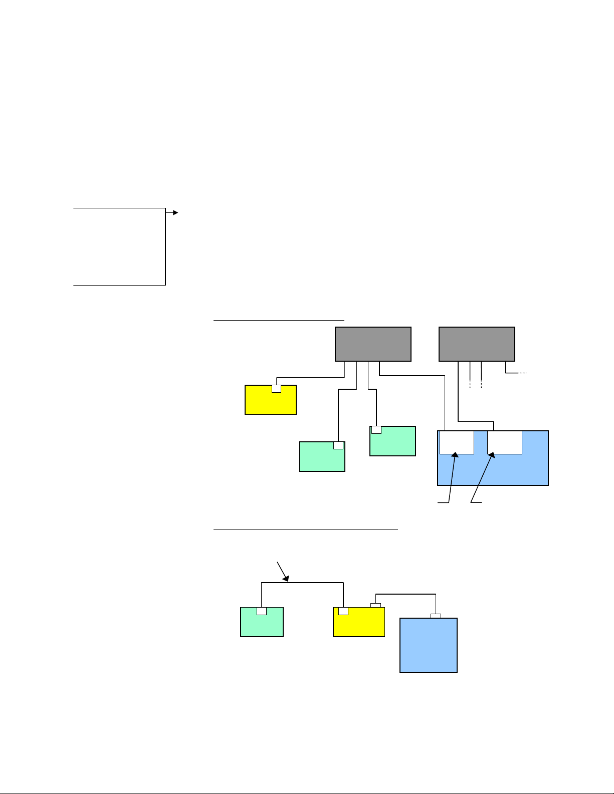
EXAMPLE — Closed Network:
6K
Client (Server to PC)
IP = 192.168.10.30
Device 1
Server
IP = 192.168.10.120
Ethernet Switch
(255.255.255.0)
out
Device 2
Server
IP = 192.168.10.80
Client
IP = 192.168.10.31
Ethernet Switch
(255.255.0.0)
out
Connection to
company network
Ethernet
Card
Ethernet
Card
IP = 172.20.44.180
PC
page 1
EXAMPLE — Direct Connect to One Server:
Crossover Cable
provided in 6K ship kit
(p/n 71-017635-01)
Device
6K
Serial Cable
PC

• 6K as a server. The 6K waits for a PC to establish a connection with it and then provides
information on a continual or requested basis. The PC communicates with the 6K using
the COM6SRVR Communications Server, which is also what Motion Planner uses to
communicate with the 6K (for details, refer to the COM6SRVR Communications Server
Programmer’s Reference). The 6K does not support simultaneous connections with
multiple clients (PCs).
EXAMPLE — Closed Network:
Switch or Hub
(255.255.255.0)
6K
Server
IP = 192.168.10.30
Client
IP = 192.168.10.31
Ethernet
Card
EXAMPLE — Direct Connect to PC:
Crossover Cable
provided in 6K ship kit
(p/n 71-017635-01)
6K
Server
IP = 172.20.34.30
Ethernet
Card
Switch or Hub
(255.255.0.0)
Connection to
company network
Ethernet
Card
PC
IP = 172.20.44.180
Switch or Hub
(255.255.0.0)
Connection to
company network
Ethernet
Card
PC
Client
IP = 172.20.34.160
IP = 172.20.44.180
• Combination of server and client. For example, the 6K could be the client for an
OPTO22 (server) and an Allen-Bradley PLC (server). At the same time, a software
program running on a PC could be using the 6K as a server.
Ethernet Switch
(255.255.255.0)
out
6K
Client (Server to PC)
IP = 192.168.10.30
Device 2
Device 1
Server
IP = 192.168.10.120
Server
IP = 192.168.10.80
Client
IP = 192.168.10.31
Ethernet Switch
(255.255.0.0)
out
Connection to
company network
Ethernet
Card
Ethernet
Card
IP = 172.20.44.180
PC
page 2
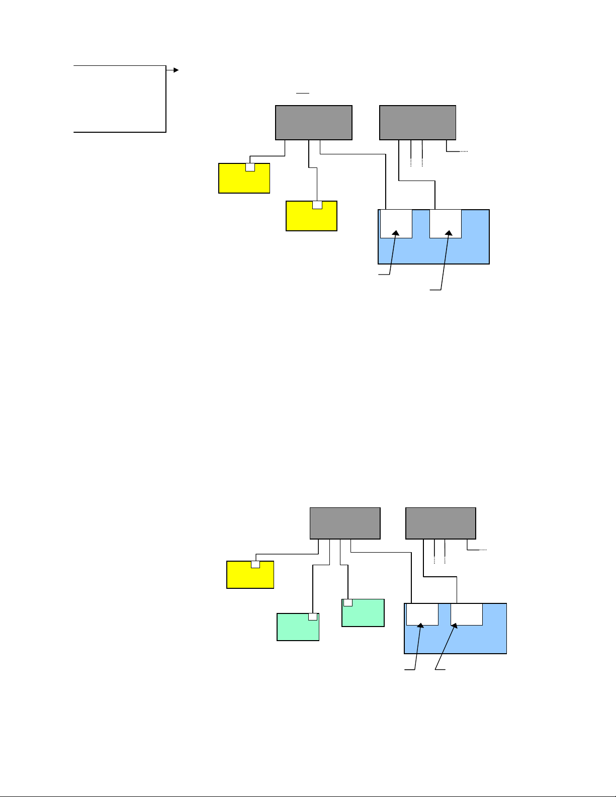
Setup Wizard Available
The Motion Planner
Wizard Editor provides a
setup wizard, called
“Network”, to help you
establish 6K peer-to-peer
communication.
• Peer-to-peer network with other 6K or Gem6K units. The 6K may be connected to
other 6K devices (6K Controllers or Gem6K drive/controllers) via Ethernet. Up to eight
6K devices may be networked in this manner. This type of connection uses UDP
broadcasting and is not
a client/server relationship. (see page 8 for setup procedures)
Ethernet Switch
(255.255.255.0)
out
Ethernet Switch
(255.255.0.0)
out
IP = 192.168.10.30
Networking Guidelines
• Use a closed network. Because of network broadcasts, it is best to put the 6K, along
with any associated server devices, on a closed network with its own subnet. If you
have a PC connected to the Ethernet Client/Server network and the PC is also
connected to your company’s network, use one Ethernet card for the Ethernet
Client/Server network and another Ethernet card for the company network (refer to the
example below).
6K unit 1
6K unit 2
IP = 192.168.10.40
IP = 192.168.10.31
Ethernet Switch
(255.255.255.0)
Ethernet
Card
IP = 172.20.44.180
Ethernet Switch
(255.255.0.0)
out
Connection to
company network
Ethernet
Card
PC
out
page 3
6K
Client (Server to PC)
IP = 192.168.10.30
IP = 192.168.10.120
Device 1
Server
Device 2
Server
IP = 192.168.10.80
Client
IP = 192.168.10.31
Ethernet
Card
Ethernet
Card
PC
IP = 172.20.44.180
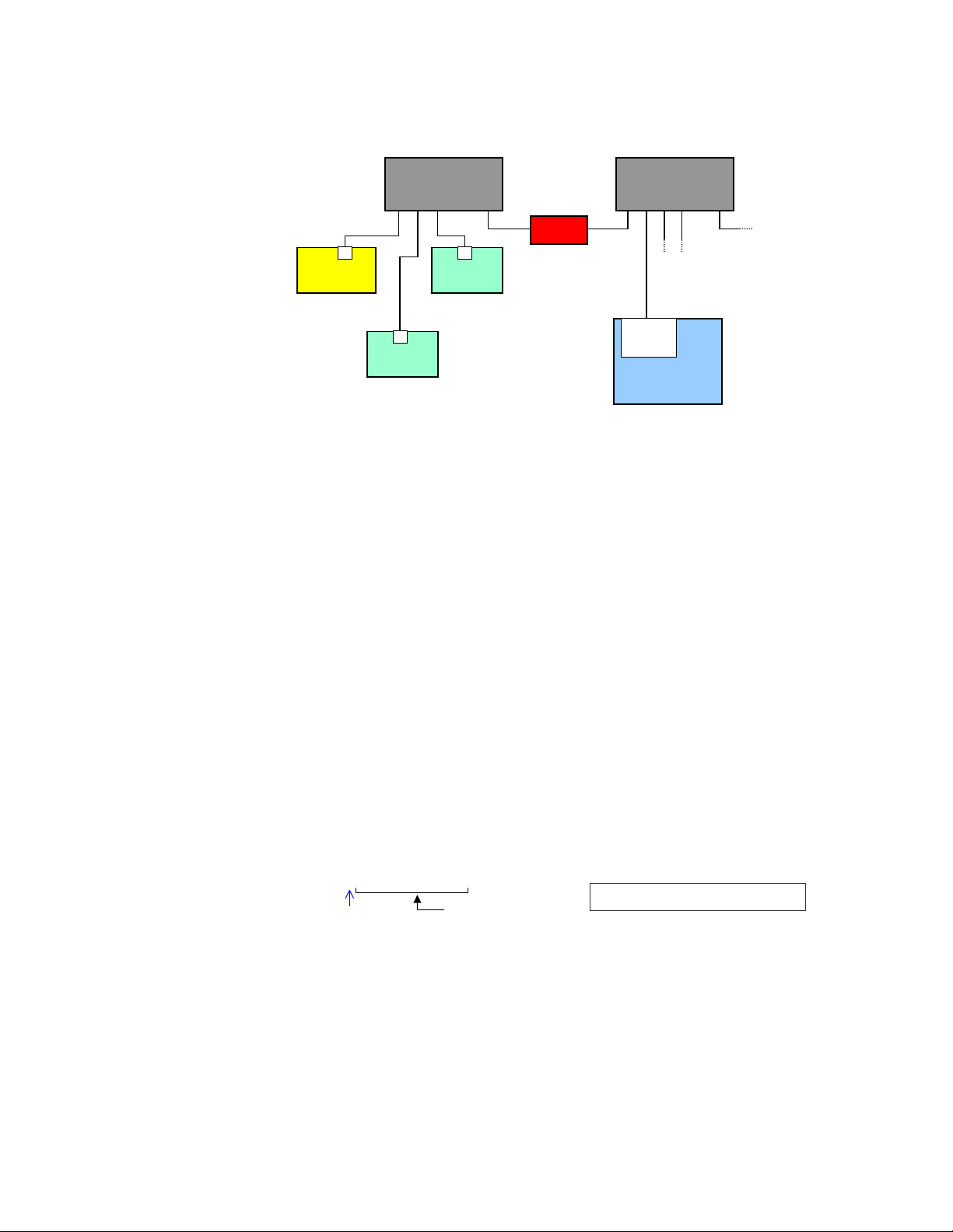
• If the 6K is placed on an open network, put the 6K and any associated server devices
p
on one side of an Ethernet network switch with its own subnet and install a bridge to
filter traffic, such that broadcast traffic does not pass in either direction (see diagram
below).
Ethernet Switch
(255.255.255.0)
out
Bridge
Ethernet Switch
(255.255.0.0)
out
6K
Client
IP = 192.168.10.30
Device 1
Server
IP = 192.168.10.120
Device 2
Server
IP = 192.168.10.80
IP = 172.20.44.180
Ethernet
Card
PC
• Use a switch (recommended) or hub if you are making more than one Ethernet
connection with the 6K.
• The 6K client must have the same subnet address as all of the server devices it will
connect to (PLC, OPTO22, DVT, etc.). For example, if the subnet mask (
NTMASK
255.255.255.0, and the subnet address is 192.168.10.*, then all devices (including the
6K) must have an address starting with 192.168.10.*, where the * number is unique to
the device.
• Fieldbus (DeviceNet or Profibus) versions of the 6K (part numbers 6Kn-DN or
6Kn-PB) cannot also communicate as an Ethernet Client at the same time.
If you have a Fieldbus unit and need to use Ethernet instead, execute the
command, then the
NTFEN1
or
NTFEN2
To re-enable Fieldbus communication, execute the
command (this disables Ethernet communication), and then the
command (this disables the Fieldbus features), and then the
RESET
command.
NTFENØ
command, then the
OPTEN1
OPTENØ
command.
RESET
) is
page 4
You cannot communicate to the 6K with simultaneous transmissions over both the
•
“ETHERNET” and “RS-232” (
PORT1
) connections.
• Follow the manufacturer’s setup procedure for each Allen-Bradley PLC, DVT camera
and OPTO22 Ethernet I/O rack.
• You should be able to ping every 6K, DVT camera, PLC and OPTO22 I/O rack from
the PC. Use the ping command at the DOS prompt:
ing 192.168.10.30
(space)
Device’s IP Address
If your PC responds with “
check your Ethernet wiring and IP address setting.
Request Timed Out
”,
• The following Ethernet setup commands need only be sent once to the 6K because they
are saved in non-volatile memory and are remembered on power-up and
NTIO, NTIP, NTMPRB, NTMPRI, NTMPWB
, and
NTMPWI
.
RESET: NTID
• If a PC is connected to the 6K/Device Ethernet network, then the PC should include all
devices in a static mapping table. The static mapping procedure, for the 6K’s address, is
found on page 6.
• If the 6K is in a peer-to-peer network, enable Ethernet communication with the
command (
NTFEN2
mode is not compatible with peer-to-peer communication).
NTFEN1
,

Configuring the 6K for Ethernet Communication
Step 1— Preparing the Controller over RS-232
Step 2—Setting
TCP/IP Properties
and Static
Mapping
Changing the 6K’s IP
Address or Subnet Mask
The factory default 6K IP
address is 192.168.10.30;
the default mask is
255.255.255.0.
If the default address and
mask are not compatible
with your network, you
may change them with the
NTADDR and NTMASK
commands, respectively
(see 6K Series Command
Reference for details on
the NTADDR and NTMASK
commands). To ascertain
the 6K’s Mac address, use
the TNTMAC command.
The NTADDR, NTMASK and
TNTMAC commands may
be sent to the 6K controller
over an RS-232 interface
(see Steps 4-6). NOTE: If
you change the 6K’s IP
address or mask, the
changes will not take affect
until you cycle power or
issue a RESET command.
There are three major steps in setting up Ethernet communication between a PC and controller:
• Step 1 prepares the 6K for Ethernet communication, and must be performed using RS-232
communication.
• Step 2 sets the TCP/IP properties on your PC to allow Ethernet communication, and
statically maps the 6K’s MAC address to the IP address of the Ethernet card in your PC.
The static mapping eliminates the PC’s need to ARP the controller, which reduces
communication overhead.
• Step 3 connects the PC to the 6K via the Ethernet.
1. Connect the 6K controller to your network (refer to Networking Guidelines on page 3).
2. Establish an RS-232 communication link between the 6K and your computer (connect to the
6K’s “RS-232” connector according to the instructions in the 6K Installation Guide).
3. Install Motion Planner on your computer, and launch Motion Planner. Click on the Terminal
tab to view the terminal emulator.
4. In the Terminal window, click on the
button to view the Communications Settings dialog.
Select the Port tab and select the COM port that is connected to the 6K’s “RS-232” connector
(see Step 2 above). Click OK.
5. In the Terminal window, enable Ethernet communication:
a. If you are using the 6K as a server or client, type the
ENTER, then type the
command and press ENTER.
RESET
NTFEN2
command and press
b. If you are using the 6K in a peer-to-peer connection with another 6K or Gem6K, type the
NTFEN1
command and press ENTER, then type the
command and press ENTER.
RESET
1. Connect the 6K controller to your network (refer to Networking Guidelines on page 3).
Install your Ethernet card and configure it for TCP/IP protocol. Refer to your Ethernet card’s
2.
user documentation for instructions. (If you need to change the 6K’s IP address or subnet mask,
refer to the note on the left.)
3.
(see illustration below) Configure your Ethernet card’s TCP/IP properties so that your
computer can communicate with the 6K controller.
a. Access the Control Panels directory.
b. Open the Network control panel.
c. In the Network control dialog, select the Configuration tab (95/98) or the Protocols tab
(NT) and double-click the TCP/IP network item to view the TCP/IP Properties dialog.
d. In the TCP/IP Properties dialog, select the IP Address tab, select “Specify an IP Address”,
type in 192.168.10.31 in the “IP Address” field, and type in 255.255.255.0 in the “Subnet
Mask” field.
e. Click the OK buttons in both dialogs to finish setting up your computer’s IP address.
page 5
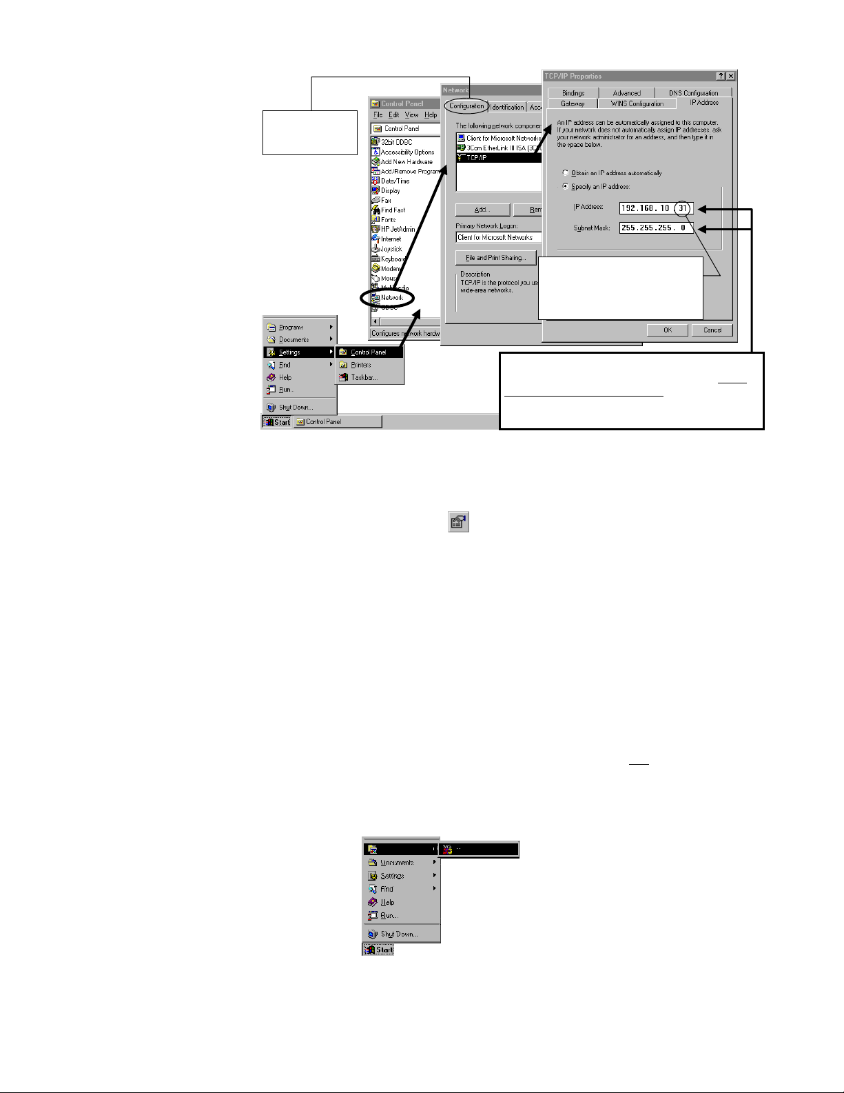
If you are using
Windows NT, select
the “Protocols” tab.
Make sure this number is different
from the one in the 6K’s IP address.
If the 6K’s default IP address is
unchanged (192.168.10.30), then
select a number other than 30.
If you are using a computer (Ethernet card) that is
normally connected to a network, you should write
down the existing IP Address and Subnet Mask
values, so that you may restore them later.
NOTE
4. Establish an RS-232 communication link between the 6K and your computer (connect to the
6K’s “RS-232” connector according to the instructions in the 6K Installation Guide).
5. Install Motion Planner on your computer, and launch Motion Planner. Click on the Terminal
tab to view the terminal emulator.
6. In the Terminal window, click on the
button to view the Communications Settings dialog.
Select the Port tab and select the COM port that is connected to the 6K’s “RS-232” connector
(see Step 4 above). Click OK.
7. In the Terminal window, enable Ethernet communication with the appropriate
NTFEN
command:
a. If you are using the 6K as a server or client, type the
then type the
command and press ENTER.
RESET
NTFEN2
command and press ENTER,
b. If you are using the 6K in a peer-to-peer connection with another 6K or Gem6K, type the
NTFEN1
command and press ENTER, then type the
command and press ENTER.
RESET
8. Use the following sub-procedure to statically map the 6K’s Ethernet MAC address to IP
address of the Ethernet card in your PC. Static mapping eliminates the need for the PC to
ARP the 6K controller, thereby reducing communication overhead.
In Motion Planner’s Terminal window, type
a.
and press ENTER. The response
TNT
includes the 6K IP address, and the 6K Ethernet address value in hex
(this is also
known as the “MAC” address). Write down the IP address and the Ethernet address
(hex value) for later use in the procedure below.
page 6
b. Start a DOS window. The typical method to start a DOS window is to select MS-DOS
Prompt from the Start/Programs menu (see illustration below).

c.
p
At the DOS prompt, type the
arp –s 192.168.10.30 0-90-55-0-0-1 192.168.10.31
arp –s
command (see example below) and press ENTER.
Spaces
(press the space bar)
6K’s IP Address
(from
d.
To verify the mapped addresses, type the
TNT
report)
If you receive the response “
Switch to the Motion Planner Terminal window, type NTFEN2 (or NTFEN1 if using a
1)
6K’s Ethernet Address
(from
TNT
report)
arp –a
No ARP Entries Found
IP Address of Ethernet Card
command and press ENTER.
”:
peer-to-peer network) and press ENTER, then type RESET and press ENTER.
Switch the DOS window, type the ping command and press ENTER: to
2)
ing 192.168.10.30
(space)
Repeat the arp –s command as instructed above. Use arp –a to verify.
3)
6K’s IP Address (from
TNT
report)
If your PC responds with “
Timed Out
wiring and IP address setting.
”, check your Ethernet
4) Switch to the Motion Planner Terminal window, type NTFEN2 (or NTFEN1 if using a
peer-to-peer network) and press ENTER, then type RESET and press ENTER.
e. (OPTIONAL) Automate the
arp –s
static mapping command. This allows your PC
to automatically perform the static mapping when it is booted; otherwise, you will
have to manually perform static mapping every time you boot your PC.
• Windows 95/98: Add the
• Windows NT:
Create a batch file that contains the arp –s command. Save the file
arp –s
(name the file “6KARP.BAT”) to the root directory on the C drive. Using Windows
Explorer, locate the 6KARP.BAT file, create a shortcut, then cut and paste the shortcut
into the StartUp directory. Windows NT has several StartUp directories to accommodate
various user configurations. We recommend using the Administrators or All Users
locations. For example, you can paste the shortcut into the
WinNt\Profiles\AllUsers\StartMenu\Programs\StartUp directory, allowing all users to
statically map the IP and Mac addresses whenever the PC is booted.
command to the Autoexec.bat file.
Request
Step 3—
Connecting the 6K
to the PC through
Ethernet
1. Connect the 6K Controller to your computer using a cross-over 10Base-T cable (5-foot cable
provided in ship kit).
2. In Motion Planner’s Terminal window, click the{bmc b_comset.bmp} button to view the
Communications Settings dialog. Select the Port tab, select “Network” and type the IP
address (192.168.10.30) in the text field. Click OK.
You may now communicate to the controller over the Ethernet interface. Reminder: You
cannot communicate to the 6K with simultaneous transmissions over both the “ETHERNET”
and “RS-232” (PORT1) connections.
(located on the RJ-45 “ETHERNET” connector):
Ethernet Connection Status LEDs
• Green LED turns on to indicate the Ethernet physical connection is OK.
• Yellow LED flashes to indicate the 6K is transmitting over the Ethernet interface.
page 7

Networking with Other 6K or Gem6K Products (Peer-to-Peer)
You can communicate information between 6Ks and Gem6Ks over Ethernet. This feature uses
UDP broadcasting over the subnet to transfer data, so no client/server connection is needed.
Up to 8 different 6K or Gem6K devices can share information, with each device having access
to shared data from the 7 other devices. Each device can broadcast 8 pieces of information
using “shared output” variables (
VARSHO1 through VARSHO8
information you can assign to a “shared output” variable.
). The following table lists the
Setup
..........Acceleration
A
........Deceleration
AD
.....Analog input voltage
ANI
.....Analog output voltage
ANO
........Axis status
AS
.....Extended axis status
ASX
..........Distance
D
.....DAC output value
DAC
...RP240 keypad value
DKEY
........Error status
ER
........Feedback device pos.
FB
........Following status
FS
........Input status
IN
.....Enable input status
INO
.....Limit input status
LIM
.....Axis moving status
MOV
... Master cycle number
NMCY
..... Output status
OUT
... Analog input position
PANI
....... Commanded position
PC
..... Captured command pos.
PCC
..... Captured encoder pos.
PCE
... Captured master enc. pos. V............Velocity
PCME
....... Encoder position
PE
..... Position error
PER
... Position of Master
PMAS
..... Master encoder pos.
PME
... Net position shift
PSHF
... Follower pos. command
PSLV
....... Controller status
SC
... PLC scan time
SCAN
..... Free segment buffers
SEG
..........System status
SS
SWAP
TASK
........Timer value
TIM
TRIG
..........User-defined status
US
VARI
VARB
........Commanded velocity
VEL
VELA
VMAS
VARSHI
......Task swap assignment
......Task number
......Trigger interrupt status
......Integer variable
......Binary variable
......Actual velocity
......Velocity of the master
.Shared input variable
The data can be either binary, as in the AS (axis status) operand, or a 32-bit unscaled integer, as
(encoder position) operand. The data stored in the
in
The
PE
NTRATE
command sets the rate at which each controller broadcasts its updated
VARSHO
data. RECOMMENDATION: Set all devices to broadcast at the same
is not scaled.
NTRATE
VARSHO
rate of 50
milliseconds.
For 6K or Gem6K sending and/or receiving information via the Peer to Peer feature:
1. Connect the 6K/Gem6K products to the network and configure each 6K/Gem6K for
Ethernet communication according to the procedures on page 4.
2. Set the broadcasting rate with
NTRATE
command, preferably the same for each unit.
3. If the unit is to receive data only (not send) you are finished with the setup for that unit.
If the unit is to send also, complete steps 4 and 5.
4. Assign a unique unit number (1-8) with the
5. Assign data to the eight broadcast variables with the
NTID
command.
VARSHO
command.
6. Repeat steps 2-5 for each unit in the peer-to-peer network.
page 8
Example
First 6K or Gem6K:
NTID1 ; Assign this unit a peer-to-peer unit number of 1
VARSHO1 = 1A ; Shared variable #1 contains axis 1's acceleration
VARSHO2 = 1PE ; Shared variable #2 contains axis 1's encoder position
; ***********************************************************************
; * Use this space to define shared output variables VARSHO3 – VARSHO7. *
; ***********************************************************************
VARSHO8 = VARI1 ; Shared variable #8 contains the value of VARI1
NTRATE50 ; Set the broadcasting rate to 50 milliseconds
Second 6K or Gem6K:
NTID2 ; Assign this unit an ID of 2
VARSHO1 = 1D ; Shared variable #1 contains axis 1's programmed distance
VARSHO2 = 3PE ; Shared variable #2 contains axis 3's encoder position
; ***********************************************************************
; * Use this space to define shared output variables VARSHO3 – VARSHO7. *
; ***********************************************************************
VARSHO8 = 1ANI.1 ; Shared variable #8 contains the voltage value at analog

Program Interaction
; input 1 on I/O brick 1
NTRATE50 ; Set the broadcasting rate to 50 milliseconds
Third 6K or Gem6K:
NTRATE50 ; Set the broadcasting rate to 50 milliseconds
; This third unit will receive data only. Therefore, it does not require
; a unit ID number or VARSHO data assignment
Each Unit can read the broadcast variables of each other unit with the
The “n” specifies the ID number (
VARSHO
VARSHO8
number of that unit to be read. For example, if you want unit 1 to read unit 2’s
data, then use
2VARSHI8
) of the unit you want to read from, the “i” is the
NTID
.
nVARSHIi
command.
Using the
VARSHI
command, you can process data from the
to-peer unit. Use the following ways:
• Assign the
VARSHO
data to a
For example, the command
to the
• Assign the VARSHO
the binary value of
• Use the
integer variable.
VARI1
VARSHO
data to a virtual input (IN). For example,
VARSHO3
data in a conditional expression for an IF,
statement. For example, if
onboard trigger input 3 (
unit 1 wait until trigger input 3 on unit 2 was on:
Example
First 6K or Gem6K (unit 1):
VARI1 = 2VARSHI8 ; Assign Unit 2's VARSHO8 (which is the voltage value
; at analog input 1 on I/O brick 1) to VARI1.
Second 6K or Gem6K (unit 2):
VARI100 = 1VARSHI2 ; Assign Unit 1's VARSHO2 (which is the encoder position
; of axis 1) to VARI100.
Third 6K or Gem6K (reading data only):
VARI90 = 1VARSHI1 ; Assign Unit 1's VARSHO1 (which is the acceleration of
; axis 1) to VARI90.
Networking with OPTO22 SNAP I/O
(numeric),
VAR
VARI1=2VARSHI8
(integer), or
VARI
assigns the value of
from unit 2 to virtual input brick 3.
VARSHO5
VARSHO5=IN.3
on unit 2 is assigned is assigned the status of
), then you could use this command to make
WAIT(2VARSHI5=b1)
VARSHO
WAIT, WHILE
variable of another peer-
(binary) variable.
VARB
, or
UNTIL
on unit 2
assigns
VARSHO8
3IN=2VARSHI3
.
page 9
Setup
The 6K client can communicate with the OPTO22 SNAP I/O server to read digital and analog
inputs and outputs, and write digital and analog outputs. The 6K supports up to eight modules
per OPTO22.
1. Follow the manufacturer’s setup procedure for the OPTO22 Ethernet I/O rack.
2. Connect the 6K and OPTO22 products in a network and configure the 6K for Ethernet
communication according to the procedures on page 4.
3. Choose a Server Connection Number for this device. The 6K can support up to 6
simultaneous server connections. Pick a number (1-6) that has not been used already for
another connection. This will be used to reference the OPTO22 unit from now on.
4. Enter the IP address of the OPTO22 and specify a 2 for connection type with the
NTIP
command. For example, if the OPTO22 is Server #3 and its IP address is 172.20.34.170,
then the command would be
3NTIP2,172,20,34,170
5. Attempt a connection to the device with
the command would be
is set (see
set (see
NTS, TNTS, TNTSF
ER, TER, TERF
3NTCONN1
).
. If the connection is successful, Network Status bit #1
). If the connection is unsuccessful, Error Status bit #23 is
NTCONN
.
. For example, if the server number is 3,
6. Inform the 6K of the configuration of the OPTO22. For each module position, use the

command to specify the type of module in that position.
NTIO
n \ m NTIO <i>
Example
Program Interaction
Network Server #
Range: 1-6
Module Type. Options are:
1 = Digital/Discrete Inputs
2 = Digital/Discrete Outputs
3 = Analog Inputs
4 = Analog Outputs
Module # on Server “n”
Range: 0-7
For example, if there is a digital input module in slot 0, then the command would be
3\0NTIO1
3\7NTIO3
7. Set the polling rate with the
example, to set the polling rate to 50 ms on server #3, use the
. If there is an Analog Input module in slot 7, then the command would be
.
NTPOLL
command. 50 milliseconds is recommended. For
3NTPOLL50
command. If
there is an error during polling, then Error Status bit #24 will be set.
NTADDR172,34,54,123 ; Set the IP address of the 6K
OPTEN0 ; Disable the option card (for Fieldbus units only)
RESET
NTFEN2 ; Enable network function on 6K
RESET
DEL OPTOSU
DEF OPTOSU
2NTIP2,172,34,54,124 ; Identify an OPTO22 device as Server #2, which is
; located at IP address 172.34.54.124
2NTCONN1 ; Attempt connection to Server #2 (OPTO22)
2\1NTIO2 ; Configure OPTO22 module 1 as digital output
2\2NTIO2 ; Configure OPTO22 module 2 as digital output
2\3NTIO1 ; Configure OPTO22 module 3 as digital input
2\4NTIO3 ; Configure OPTO22 module 4 as analog input
2NTPOLL50 ; Begin polling, set polling interval to 50 ms
END
Once the OPTO22 is configured and a connection is made, you can then set outputs and check
inputs.
How the 6K addresses OPTO22 I/O locations:
The 6K addresses each I/O bit by its location on a specific module. (NOTE: I/O points are
not addressed by an absolute 32-bit location on the OPTO22.) Digital input and output
modules have four I/O points, or channels, and are numbered 1-4. Analog input and output
modules have two I/O points, or channels, and are numbered 1-2.
EXAMPLE: OPTO22 is Network Server #3
0
Digital
Input
Module
Input
1
Input
2
Input
3
Input
4
3\0IN.3 3\3OUT.2 3\5ANO.1 3\7ANI.2
• To verify the I/O configuration (as per
inputs and outputs, type
n\TIO
• To set a digital output, type
module number, “
= off). To set multiple digital outputs on the same module, type
0
” is the point number on that module and “b” is the state (1 = on,
i
1
Digital
Input
Module
Input
1
Input
2
Input
3
Input
4
2
Digital
Output
Module
Output
1
Output
2
Output
3
Output
4
NTIO
3
Digital
Output
Module
Output
Output
Output
Output
Analog
Output
Module
Output
1
Output
2
3
4
) and to check the status of each module’s
, where “n” is the server number.
n\mOUT.i-b
, where “n” is the server number, “m” is the
Ot t#1
4
1
2
5
Analog
Output
Module
Output
1
Output
2
6
Analog
Input
Module
Input
1
Input
2
n\mOUTbbbb
:
7
Analog
Input
Module
Input
1
Input
2
page 10

Output #1
Output #2
Output #3
Output #4
n \ m OUT b b b b
Network Server #
Range: 1-6
Module # on Server “n”
Range: 0-7
Options for “b” are:
1 = Turn on
0 = Turn off
x = Don’t Change
For example (Server #3), to turn on outputs #1 and #4 and leave outputs #2 and #3 unchanged on module #2, type
3\2OUT1XX1
. To turn off only output #4, type
3\2OUT.4-0
.
• To set an analog output voltage, type
n\mANO.i-r
, where “n” is the server number, “m” is
the module number, “i” is the output number on that module and “r” is the voltage. For
example, to set analog output #1 on module #5 of Server #3 to 6.4V, type
3\5ANO.1=6.4
• To read a digital input or output module, use the assignment/comparison operands (
or
n\mOUT
- IF(3\0IN=b1100) is an IF condition that reads all four digital inputs on module #0.
- IF(3\2OUT=b1100) is an IF condition that reads all four outputs on module #2.
- 3\0TIN transfers the binary status of all four digital inputs on module #0.
- 3\2TOUT transfers the binary status of all four digital outputs on module #2.
) or the transfer commands (
IF(3\0IN.2=b1) is an IF condition that reads only digital input #2 on module #0.
IF(3\2OUT.3=b1) is an IF condition that reads only digital output #3 on module #2.
3\0TIN.2 transfers the binary status of only digital input #2 on module #0.
3\2TOUT.3 transfers the binary status of only digital output #3 on module #2.
n\mTIN
or
n\mTOUT
). Following are examples:
• To read an analog input or output module, use the assignment/comparison operands
(
n\mANI
or
n\mANO
) or the transfer commands (
n\mTANI
or
n\mTANO
). Following are
examples:
- WAIT(3\7ANI.2<2.4) is an WAIT condition that reads analog input #2 on module #7.
- IF(3\5ANO.1>=1.0) is an IF condition that reads analog output #1 on module #5.
- 3\6TANI transfers the voltage status of both analog inputs on module #6.
3\6TANI.2 transfers the voltage status of only analog input #2 on module #6.
- 3\4TANO transfers the voltage status of both analog outputs on module #4.
3\4TANO.1 transfers the voltage status of only analog output #1 on module #4.
n\mIN
.
Networking with a DVT Vision System
The controller can send trigger commands to the camera. The camera should send back ASCII
page 11
Setup
strings similar to what follows:
assignments set apart by commas. The values are then written to the controller’s
VAR
This data can represent anything, such as an x-y coordinate.
1. Follow the manufacturer’s setup procedure for the DVT camera.
2. Connect the 6K and DVT camera in a network and configure the 6K for Ethernet
communication according to the procedures on page 4.
3. Choose a Server Connection Number for this device. The 6K can support up to 6
simultaneous client connections. Pick a number (1-6) that has not been used already for
another server connection. This will be used to reference the device from now on.
4. Enter the IP address of the camera and specify a 3 for connection type with the
command. For example, if the DVT camera is Server #6 and its IP address is
172.20.34.150, then the command would be
5. Attempt a connection to the device with
the command would be
#1 is set (see
is set (see
NTS, TNTS, TNTSF
ER, TER, TERF
VARn = 123.456, VARm = 234.567
6NTCONN1
).
. The ASCII strings are
s;
VAR
NTIP
6NTIP3,172,20,34,150
NTCONN
. For example, if the server number is 6,
.
. If the connection is successful, Network Status bit
). If the connection is unsuccessful, Error Status bit #23
 Loading...