

Page 1
Automation
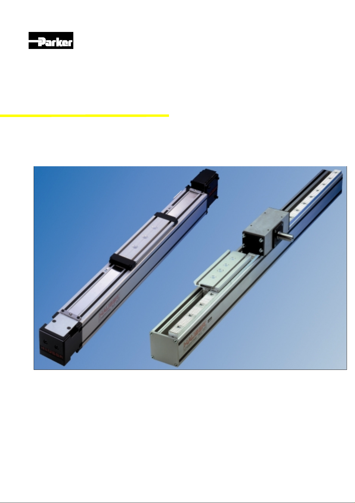
Linear actuators
HLE with timing belt drive
HLEZ with rack-and-pinion drive
Catalogue: 192-510011N7
Version 7 / May 1999
Page 2

HLE – Linear actuators with timing belt drive
Automation
2
Parker Hannifin GmbH
Electromechanical Division
Page 3
HLE – Linear actuators with timing belt drive
g g
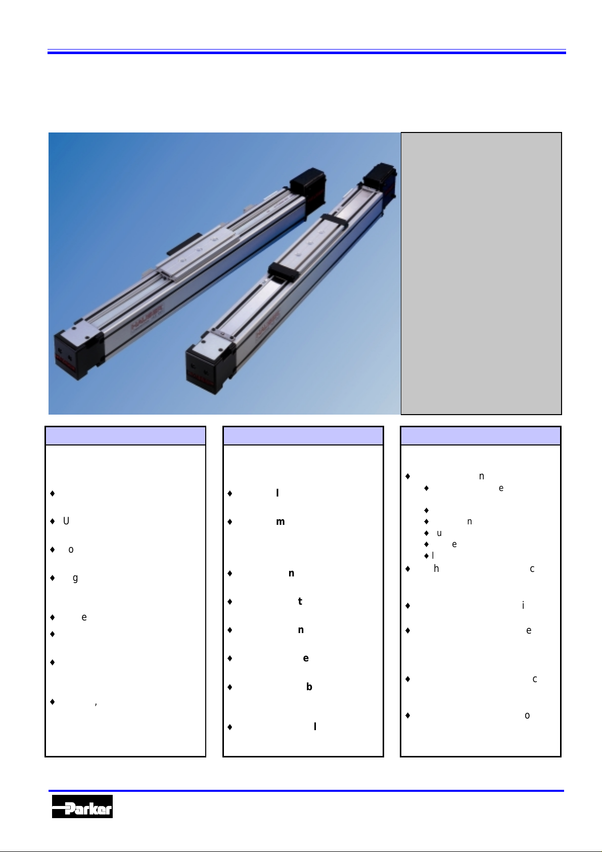
HLE linear actuators with timing belt drive
- for guiding, transporting and positioning -
Contents:
The HLE - a proven technology.............. 4
Construction of the HLE..........................5
Technical data..........................................6
Dimensional drawings.............................8
HLE 80......................................................8
HLE100...................................................10
HLE 150..................................................12
Idler unit.................................................14
Carriage with bar ..................................14
Order code .............................................15
HLEZ linear actuators with rack-and-
pinion drive.............................................17
Mechanical accessories........................ 25
Assembly angle plate...........................25
Clamping profile ...................................26
T-nuts and bolts....................................26
Link shaft bearing.................................27
External buffer stop..............................27
Cable carrier..........................................28
Longitudinal flange connection set....30
Attachment of position sensors ..........31
Tripping plate........................................32
Mechanical limit switch........................33
Electrical limit switch...........................33
Distribution box....................................34
Other accessories and software...........34
The dynamic linear unit Typical fields of application Proven technology
for gui ding, transporting and positioning, even over long distances,
offers:
i
High speeds in practical appli -
cations of up to 7 m/s
i
Up to 108 Nm permitted dr iv-
ing torque
i
Long travel distances, up to
20 m
i
High load capacity, horizontal
up to 1000 kg /, vertical up to
300 kg
i
Repeatability, up to ±0.05 mm
i
High mechanical effic iency of
95 %
i
Three prof ile sizes: HLE80,
HLE100 and HLE150, can be
combined in a modular system
i
Simple, rapid installation and
start-up
as part of advanced, cost-effec tive construction of m ac hines and
handling systems:
i
Materials handling
e.g. pal-
letization, feeding, withdrawal
i
Textile machinery building
e.g. cross-cutt ing, slit ting and
stacking, quilting, seam stitching
i
Process engi neering
e.g.
painting, coating, bonding
i
Warehouse technology
e.g.
picking, storage
i
Construction
e.g. f or mwork,
placing reinforcing steel
i
Clean room technology
e.g.
wafer transport, wafer coati ng
i
Machine tool building
e.g.
loading wit h workpiece, tool
changing
i
Testing technology
e.g.
guiding ul trasonic sensors
Subject to technical m odification. Data correct at time of printi ng 06/99
proven in numerous applications,
offers the fol lowing advantages:
i
Low-friction runnin
i
Low particle generation (clean
room suitability to class 10)
i
low wear
i
zero maintenance
i
quiet running
i
high efficiency and
i
long service life
High dynamic perfor mance
i
uaranteed:
due to low-mass, pl ay - free
wheels
Simplif ied inspection with long
i
inspection intervals.
Longitudinal groov es i ntegra-
i
ted on all sides of the profile
for mounting att ac hments or
for use as a cable duct
Tim ing belts can be repl aced
i
without dismantling load attachment plate.
Flex ible installation options
i
provided by longitudinal grooves in the load attachment
plate.
Automation
3
Parker Hannifin GmbH
Electromechanical Division
Page 4
HLE – Linear actuators with timing belt drive
The HLE - a proven technology
The universal one
The HLE linear actuator offers an appropriate solution for all motion tasks.
It is ideal for use as a single axis, or as
a component in a m ul tiple axis system.
It has been developed for rapid linear
movements over long stroke distances.
The HLE provides a simple machine
and system element and can be used
without the need for any specialised
knowledge. Installation and start ing up
only requires a small amount of effort
from the user. The HLE is supplied in
many different configurations with numerous options and many accessories.
The HLE drive principle
The HLE consists of an extruded, selfsupporting aluminium profile, inside
which a backlash-free wheeled carriage
is moved by a timing belt.
Our experience
You can have confidence in our experience and skill because over 6000 axes
are already in use throughout t he world
- be it in automatic textile equipment,
handling systems, packaging machines, automat ic painting and bi nding
equipment ...etc.
The HLE can be found in a wide range
of applications: in clean rooms, in the
food industry, production plants in the
chemical indust r y or i n the manufacture
of prefabricated concrete components.
We work together with a wide range of
different industrial sectors including t he
automobile industry, machine tool
manufactur ers, microelectronics m anufacturers - and hopefully soon with you
...
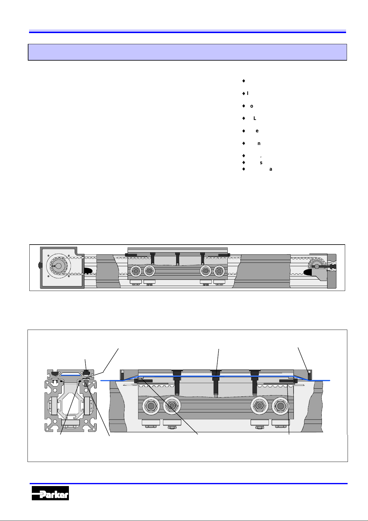
The steel cord tensile strands integrated into the belt provide the necessary stiffness and effectively prevent
belt streching.
Examples/applications
Mercedes Benz
i
supporting cockpit parts in the S-class
, Böblingen, Germany: wafer transport
IBM
i
in chip production
Bosch-Siemens Hausgeräte GmbH
i
Traunreut, Germany: ha ndling co okers
, Stuttgart, Germany: picking e l ectronic
SEL
i
components
Bitterfeld: palettising folding cartons
Bayer,
i
(flatpa ck box es) for pharmaceut icals
LT Engineering,
i
unit for small parts stores
, Steinfeld: handling roof tiles
Braas
i
Philips,
i
Weckenmann,
i
profiles in the concrete branch.
Special pulleys ensure play-free drive,
ensuring high repeatibility even with
long travel paths and high speeds.
, Sindelfingen, Germany:
,
Switzerland: shelf-picking
Holland: handling screen masks
Dormettingen: setting shell
Optional steel strip cover
A totally new steel strip cover concept
applies fully to the HLE-design. It re-
The T-grooves of the load attachment plate and the basic HLE profile are suitable for T-nuts in accordance with DIN508 and T-bolt in
accordance with DIN 787 (T-nuts
and bolts: refer to page 26)
Ma gnetic strips recessed in the
profile ensure that the steel belt is
fully sealed with the profile
Steel plate integrated in the carriage
plate serves as switching plate for
home & limit sensors.
Switches or sensors for the end
limit or for the machine zero point
can be integrated in the T-groove of
the HLE profile
liably protects the timing belt, wheels
and the bearing surface of the profile
Protectiv e caps ensure th at no dust
enters the in terior of the HLE
Plastic inlays serve as
bearing surface for steel
strip.
against dirt ( pr ot ecti on cl ass I P30) .
A spring-loaded felt insert reliably
keeps dirt away
The timing belt is attached to the carriage
with a clamping angle piece.
The belt can be changed without dismantling the flange plate.
Automation
4
Parker Hannifin GmbH
Electromechanical Division
Page 5
HLE – Linear actuators with timing belt drive
g
g
g
g
y
y
g
g
y
g
g
g sy
g
g
g
g
y g
y
g
g
y
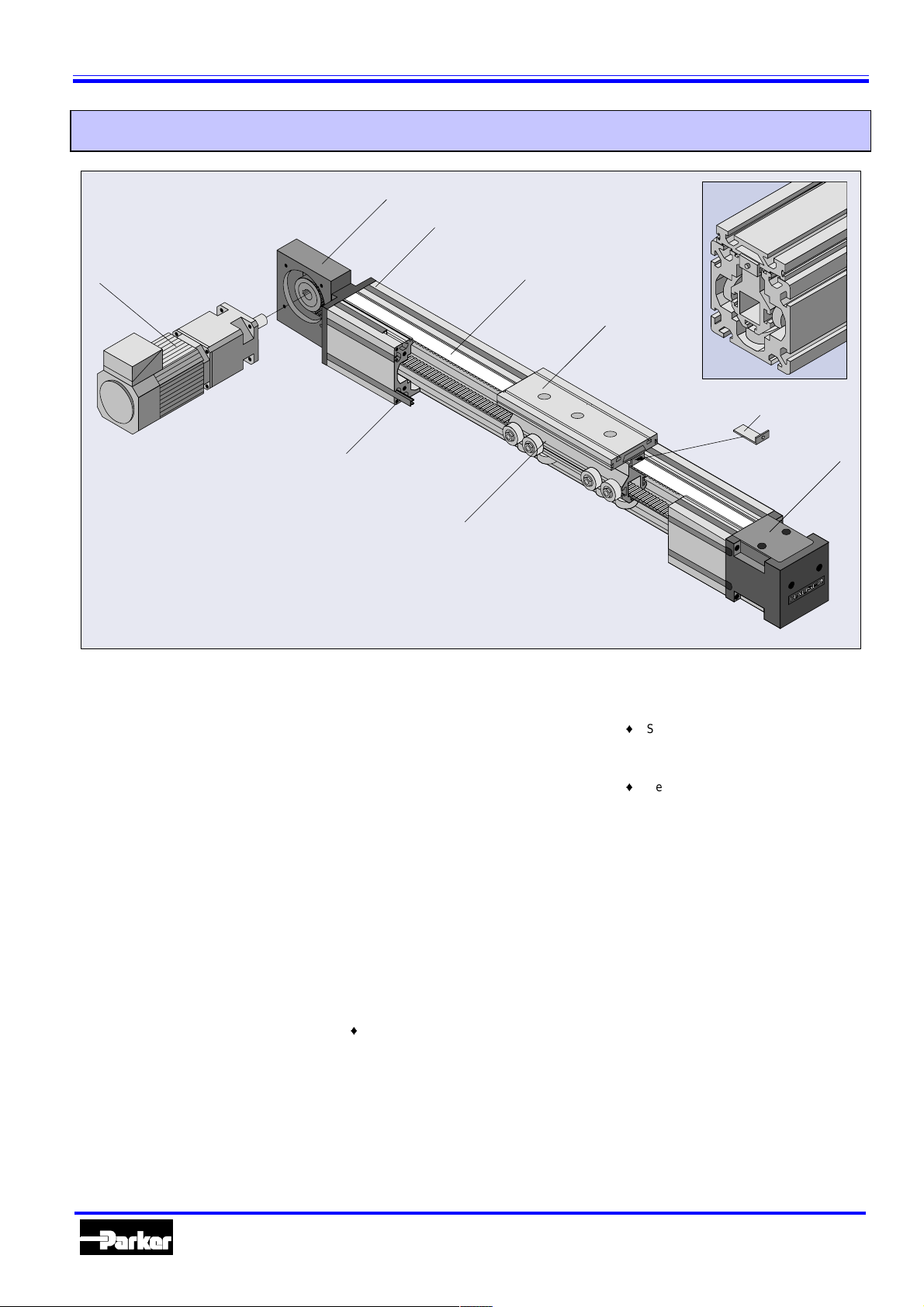
Construction of the HLE
4
1
59
7
6
The profile (1)
Light, compact and self-supporting alum inium
prof ile con stru ction. Available in t he fol lowin
cross-sections:
80x80 mm (HLE80)
100x100 mm (HLE100)
150x150 mm (HLE150)
All profi les feat ure a tot al of ei
clampin g grooves f or the attach ment of additional mechanical components and for the
connection of several HLE units. These
grooves also s erve as at tac hment and mou nting points for initiators and mechanical switches.
To
ether with the HAUSER cover profiles (8),
these can be used as cable ducts.
ht longitudinal
The carri age (2)
Light, rigid carriages with plastic rollers
moun t ed on roller bear i n
for pla
-free carriage settings on all sides.
Overall, this results in high mechanical efficienc
and virtually wear-free operation. The
carria
e can be supplied in two lengths, either
standard or extended.
We can also produce special carria
customised applications.
s and eccentric axles
es for
The tensioning station (3)
An easily maintained and assembly-friendly
tensioning station for setting the te nsio n required for the timing belt and its orientation
(parallelism of pulleys).
8
2
The d rive station (4)
Robust cast ca sing with standard flange. Man
earboxes can be directly flange-mou nted ( for
bore pattern, refe r t o dimensions).
On request, this can be supplied with the drive
shaft on the right, on the left or on both sides.
The timing belt (5)
The timing belt has no play and is reinforced
by in tegr al s teel wir es, th ereb y ens ur in g m aximum trave l spe eds and repeatability.
Clamping of timing belt (6)
The timing belt clamping angle guarantees a
secure connection between the timin
the carriage.
Th e cl ampi n
be rep laced with out t he load attac hmen t p late
havin g to be di smant led. T his means that attachments do not normally need to be remove d.
st em all ows t he t imi ng belt to
The l oad attachment plate (7)
The longitudinal grooves integrated on
i
the top of the plate offer many options for
the assembly of attachments.
belt and
3
When used in conjunction with the
clampin
simple incorporation in a multi-axis system.
Sim pl e and ad j us t abl e att ac h men t of oper -
i
atin
lon
the underside of the plate.
Hei
i
the s teel str ip cover is att ached at a later
date.
Special designs are also available on request.
The optional drive motor (9)
Parker servo motor with res olver and an approp riate pl anetar
drive for dynamic and accurate applications.
W hen used together with the COMPAX compact servo controller, the HLE becomes a
complete, read
sin
le and multi-axis travel and continuous
path controls.
The V2A version (option V)
Minimum particle emissions and high levels of
resistance to water and various cleanin
agents make th e V2A vers ion th e num ber one
ch oice for use in clean r ooms or the food industry.
Th e st eel c om pon en ts ar e mad e of V 2A m aterial and the rollers and pulle
fitted w ith corrosion-resistant bearings.
profile (page 26) this allows for
cams or switch lugs by means of
itudinal grooves on the sides and on
ht and bolt points are unaffected when
earbox f orm an optimum
-to- run aut omation system for
mountings are
Automation
5
Parker Hannifin GmbH
Electromechanical Division
Page 6
HLE – Linear actuators with timing belt drive
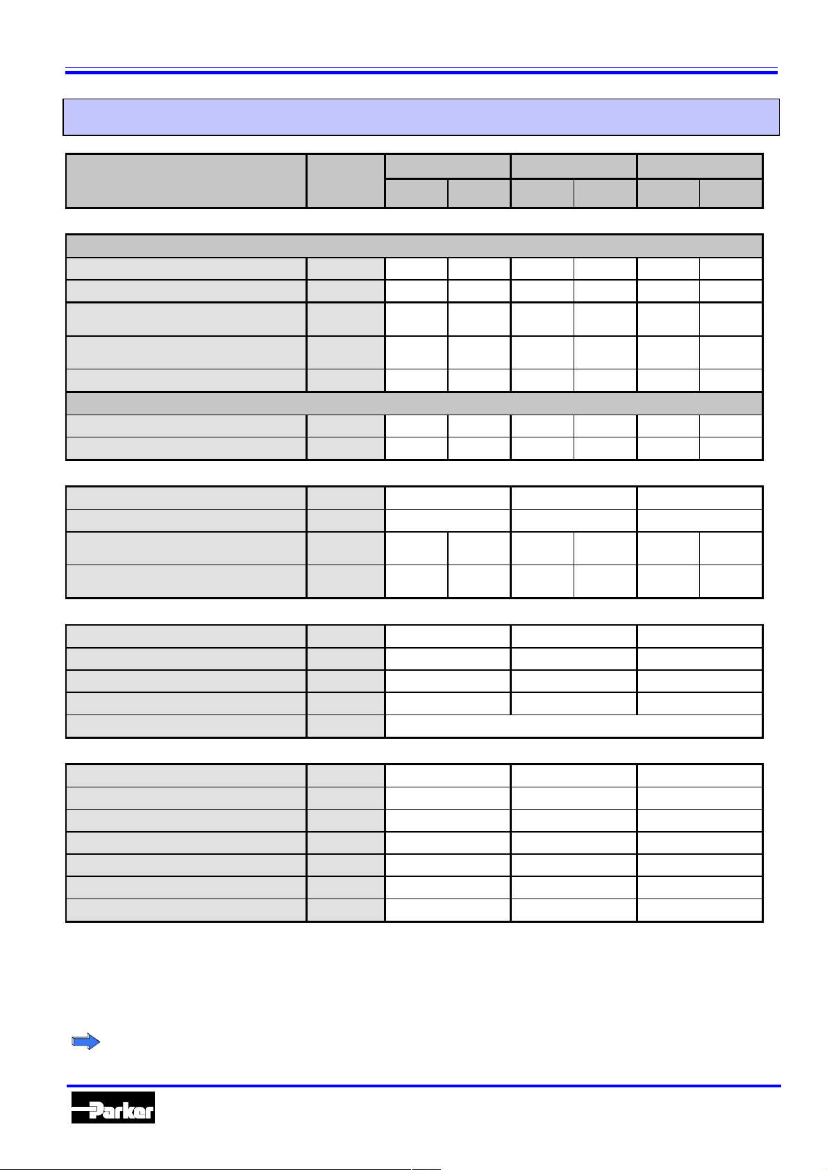
Technical data
HLE size 80 100 150
Unit
Standard
Steel strip
cover
Standard
Weight and moment of inertia
Weight of basi c unit without strok e
HLE with standard carriage S kg 7.1 7.9 11.5 12.7 28.6 31.2
HLE with extended carriage E kg 8.4 9.9 14.6 15.8 35.9 38.5
Weight of standar d c ar r iage +
load attachment plat e S
Weight of extended carriage +
load attachment plat e E
Weight per meter of additional length kg/m 6.4 6.4 9.9 10.0 21.0 21.1
Moment of inertia related t o the drive shaft
Standard carriage S kgcm
Extended car riage E kgcm
kg 1.5 1.7 2.5 2.8 6.7 7.3
kg 2.5 2.8 4.1 4.4 10.9 11.5
2
2
18.1 20.3 22.3 24.6 114.0 123.3
27.5 29.7 34.1 36.4 174.4 183.6
Steel strip
cover
Standard
Steel strip
cover
Travel paths and speeds
Maximum tr avel speed
Maximum acceleration
Maximum tr avel path, standard
carriage S/T2 with one profile bar
Maximum tr avel path, extended
carriage E/F2 with one profile bar
1
1
m/s 5.0 5.0 5.0
2
m/s
10.0 10.0 10.0
mm 5350 5260 6300 6210 9150 9060
mm 5200 5110 6150 6060 9000 8910
Geometrical data
Cross-section mm x mm 80 x 80 100 x 100 150 x 150
Moment of inertia I
Moment of inertia I
Moment of inertia I
x cm
y cm
t cm
Modulus of elasticit y N/mm2 0.72*10
4 152 383 1940
4 177 431 2147
4 24 117 391
5
Pulley data, torques and forces
Travel distance per r evolution mm/rev 190 170 240
Pulley diameter mm 60.479 54.113 76.394
Nominal drive torque Nm 17.5 15.7 51.4
Maximum drive t or que
Nominal belt traction (effective load) N 580 580 1350
Max. belt traction3 (effective load) N 1058 1478 2827
Repeatability
Please contact HAUSER in t he event of t he f ollowing deviations f r om the standard techni cal data:
1
Travel speeds over 5m/s and acceleration over 10m/s2.
2
Longitudinal f lange connection possible for longer travel distances. This does lead to li mitati ons wi t h r egard to: maximum
permitted load, dr i v e torque, speed, acceleration and repeatability (refer to page 30)
3
Increased timing belt t ension required.
4
Repeatability up to ± 0.05 mm
4
3
Nm 32 40 108
mm ±0.2 ±0.2 ±0.2
Technical data, issued 06/99, safety factor taken into co nsideration S=1. Data a pplies for a temperature range of betw een -10°C and +40°C
Parker Hannifin GmbH
Electromechanical Division
Automation
6
Page 7
HLE – Linear actuators with timing belt drive
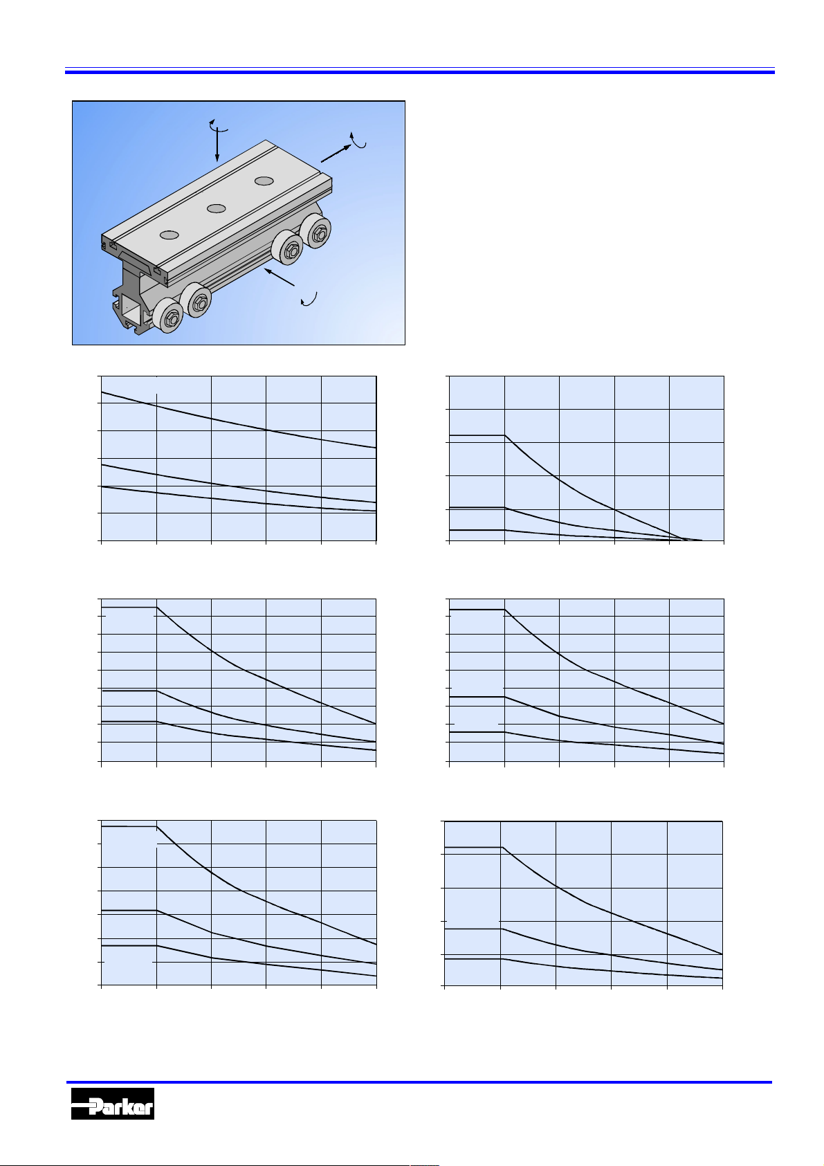
Mz
Fz
Fx
Mx
Fy
My
Fx [N] (load-be aring capac ity of timing belt)
3000
2500
2000
1500
1000
500
Fy [N]
1800
1600
1400
1200
1000
800
600
400
200
Fz [N]
3500
3000
2500
2000
1500
1000
500
HLE150c
HLE100c
HLE80c
0
012345
HLE150c
HLE100c
HLE80c
0
012345
HLE150c
HLE100c
HLE80c
0
012345
v [m/s]
v [m/s]
v [m/s]
The forces and torques the carriage and the timi ng belt are
capable of transferring ar e speed-dependent.
The curves shown in the graphs apply to a standard carr i age
(S/T).
Wi th the extended carriage (E/F), all the values apart from
Fx (load-bearing capacity of timing belt) can be doubled if
the load is applied equally to both hal ves of the carr iage or
distribut ed unifor mly along it s enti r e length.
The curves show the maximum load-bearing capacity of a
carriage in one direction of for ce or torque. If several loads
are applied in different directions, the values given by the
curves
must be derated
, i.e. the load or speed should be
reduced if necessary.
For precise carriage dimensioni ng, our software "DimAxes"
is available (Refer to "Other accessories and software", page
34).
Mx [Nm]
250
200
HLE150c
150
100
HLE100c
50
HLE80c
0
012345
My [Nm]
450
400
HLE150c
350
300
250
HLE100c
200
150
HLE80c
100
50
0
012345
Mz [Nm]
250
HLE150c
200
150
HLE100c
100
50
HLE80c
0
012345
v [m/s]
v [m/s]
v [m/s]
Automation
7
Parker Hannifin GmbH
Electromechanical Division
Page 8
HLE – Linear actuators with timing belt drive
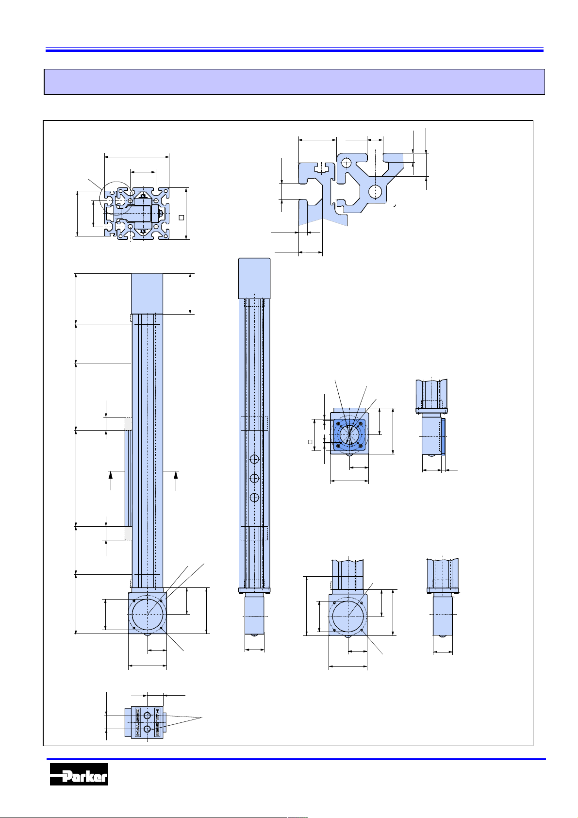
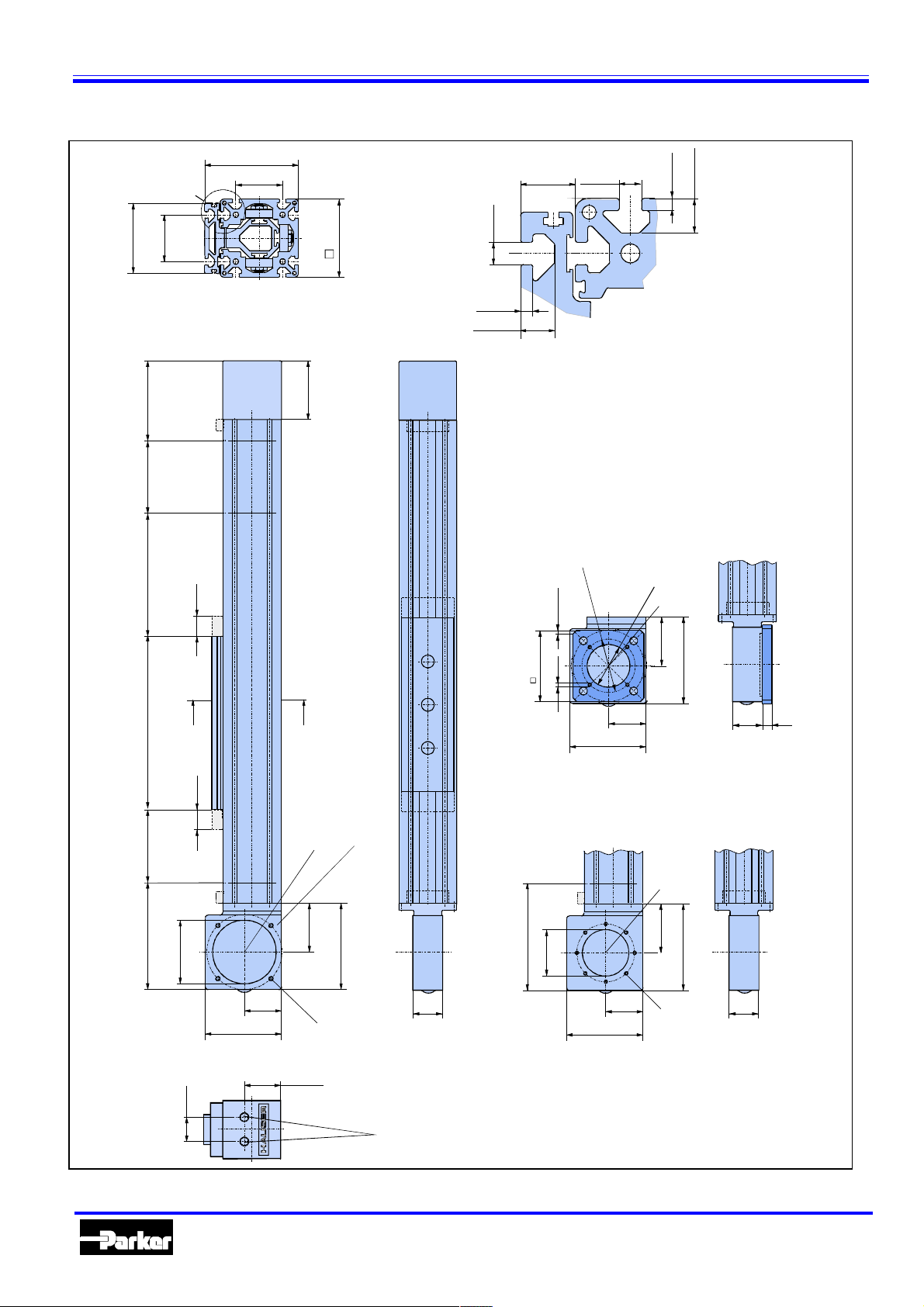
Dimensional drawings
HLE 80 single axis
Section A-A enlarged
stroke
+0,2
+0,3
4,5
12,5
Slots compatible with
DIN508 T-nuts
DIN787 T-bolts
70
20
8,1
+0,3
100
Detail X
+0,3
4,5
12,5
8,1
+0,3
+0,2
±0,3
X
±0,3
40
80
40
106
130 (175)
125
travel
Safety
7
±0,1
H
Pulley for drive shaft Ø16
Key complying with
DIN 6885 T1, type A
Ø60
(35)
Ø75
5x45°
Dimensions in () apply in combination with
steel strip cover. Pa rts indicated in broken lines:
Steel strip cover option. Casing projecti on at drive
and tensioning sta t ion approx . 1mm.
70
100
120
M5
gearbox flange A
50
40
A
gearbox flange Q
Pulley for drive shaft Ø20
+0,2
70
120
50
4xM6 Pitch
circle Ø100
H7
164 (209)
110
gearbox flange R
A
250 standard carriage
400 extended carriage
125
144 (189)
(35)
travel
Safety
H7
80
100
+0,2
100
122
50
61
Pulley for drive shaft Ø25
80
50
10
Key complying with
DIN 6885 T1, type A
140
52
4xM8 Pitch
circle Ø130
34
Timing belt
tensioning screws
Automation
8
Parker Hannifin GmbH
Electromechanical Division
Page 9
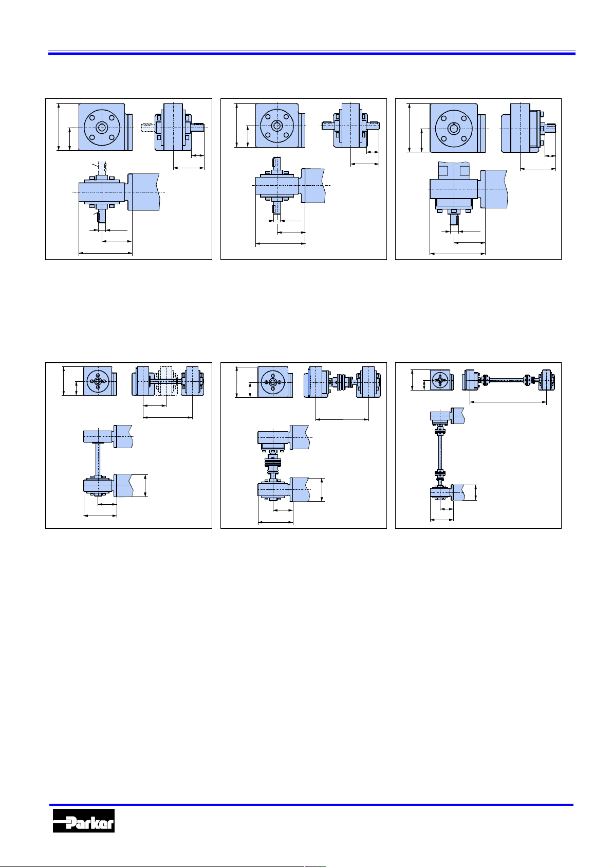
HLE – Linear actuators with timing belt drive
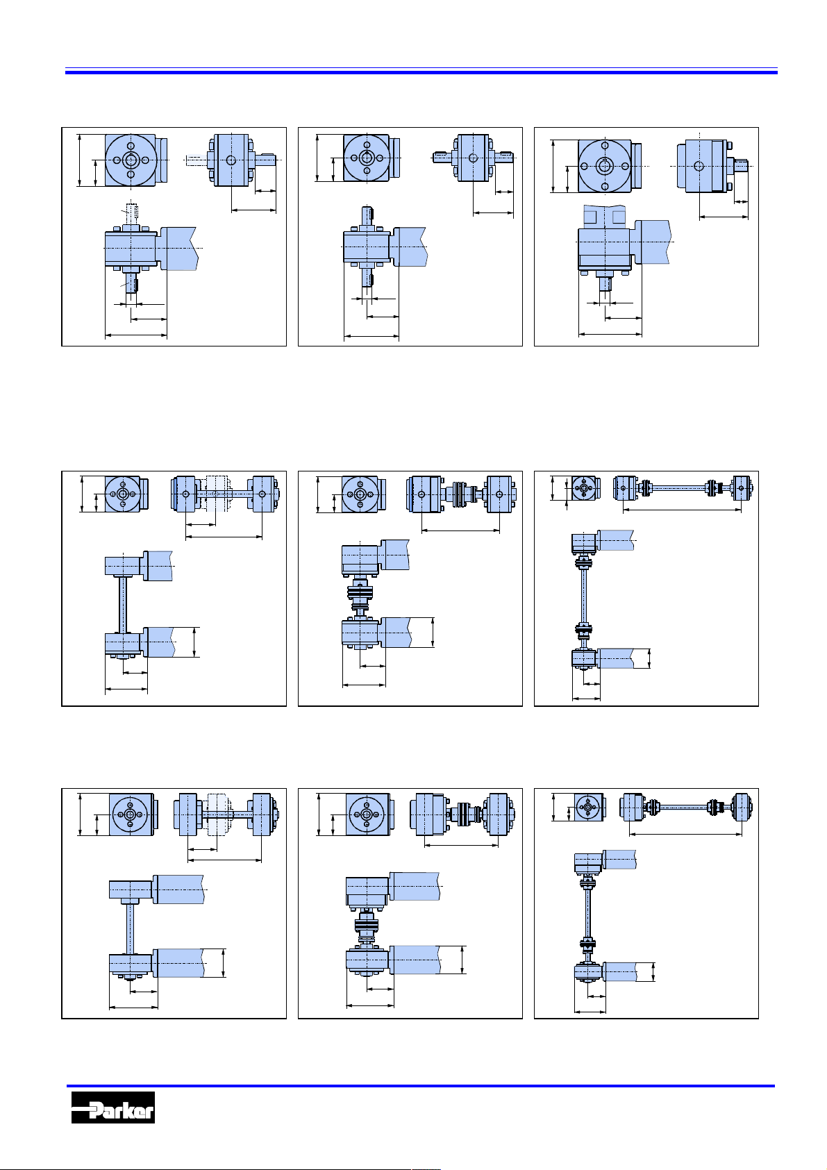
HLE80 drive housing with drive shafts
100
50
SR
SL
20
h9
70
120
SL: shaft on left
40
87
100
50
20
h6
70
120
SB: shafts on both sides RL:gearbox on right and
SR: shaft on right
HLE 80 dual axis with gearbox flange Q
100
50
80
215
100
50
215 < A < 500
87
40
100
50
120
70
20
h8
29
96
shaft on left
LR: gearbox on left and shaft
on right
100
50
A > 500
80
70
120
Centre distance A between 80215 mm
Centre distance A between
215-500 mm
70
120
HLE 80 dual axis with gearbox flange R
122
61
80
215
80
80
140
Centre distance A between 80215 mm
122
61
80
140
Centre distance A between
215-500 mm
80
A > 215
80
80
70
120
Centre distance A greater than
500 mm
122
61
80
140
A > 500
80
Centre distance A greater than
500 mm
Automation
9
Parker Hannifin GmbH
Electromechanical Division
Page 10
HLE – Linear actuators with timing belt drive
HLE100 single axis
Section A-A enlarged
90
120
60
±0,3
20
8,1
+0,3
X
+0,3
±0,3
60
100
8,1
,2
0
+
+0,3
4,5
12,5
Detail X
+0,3
4,5
+
0
,2
12,5
102
126(171)
Slots compati ble with
DIN 508 T-nuts
DIN 787 T-bolts
125174(219)
travel
Safety
Dimensions in () apply in combination with
steel strip cover. Parts indicated in broken lines:
Steel strip cover option. Casing projection at drive
and tensioning station approx. 1mm.
stroke
(35)
±0,1
Ø75
Ø60
H7
Pulley for drive shaft Ø16
Key complying with
DIN 6885 T1, type A
85
100
M5 5x45°
A
A
gearbox flange A
64,4
150
52 12
132
300 standard carriage
450 extended carriage
(35)
gearbox flange R
Pulley for drive shaft Ø25
85
±0,2
Key complying with DIN 6885 T1, type A
Pulley for drive shaft Ø20
Key complying with
DIN 6885 T1, type A
85
150
gearbox flange Q
52 52
H7
80
174(219)
150
64,4
132
4xM8 Pitch
circle Ø130
8xM6 Pitch
circle Ø100
125
travel
Safety
H7
110
64,4
132
63,4
+0,2
43
Automation
Timing belt
tensioning screw
10
Parker Hannifin GmbH
Electromechanical Division
Page 11
HLE – Linear actuators with timing belt drive
HLE100 drive housing with drive shafts
132
64,4
SR
SL
20
h9
85
150
SL: shaft on left
40
87
132
64,4
20
h6
85
150
SB: shaft on both sides RL:gearbox on right and
SR: shaft on right
HLE 100 dual axis with gearbox flanges Q and R
132
64,4
100
225
132
64,4
225<A<500
87
40
132
64,4
20
h8
85
150
40
87
shaft on left
LR: gearbox on left and shaft
on right
132
64,4
A > 500
85
100
150
Centre distance A between
100-225 mm
100
85
150
Centre distance A between
225-500 mm
85
150
100
Centre distance A greater than
500 mm
Automation
11
Parker Hannifin GmbH
Electromechanical Division
Page 12

HLE – Linear actuators with timing belt drive
HLE 150 single axis
175
25
10,1
8
Section A-A enlarged
±0,3
X
±0,3
140
90
110
146(191)
125
travel
Safety
90
150
Detail X
+0,5
+0,5
10,1
8
+0,5
8
+0,5
8
Slots compatible with
DIN508 T-nuts
DIN787 T-bolts
stroke
350 standard carriage
125
234(279)
(35)
A
500 extended carriage
(35)
travel
Safety
H7
110
104
187
A
Pulley for drive shaft Ø25
Key complying with DIN 6885 T1, type A
gearbox flange R
Dimensions in () apply in combination with
steel strip cover. Parts indicated in broken lines:
Steel strip cover option. Casing projection at drive
and tensioning sta t ion approx . 1mm.
115
198
60
4xM8
TK Ø130
54
Automation
102
Timing belt
tensioning screws
12
Parker Hannifin GmbH
Electromechanical Division
Page 13

HLE – Linear actuators with timing belt drive
HLE150 drive housing with drive shafts
187
104
SR
SL
30
h9
115
150
SL: shaft on left
56
108
187
104
30
h9
115
198
SB: shaft on both sides RL:gearbox on right and
SR: shaft on right
HLE 150 – dual axis with gearbox flange R
186
186
104
150
260
104
260 < A < 500
108
56
187
104
45
123
30
h9
115
198
shaft on left
LR: gearbox on left and shaft
on right
186
104
A > 500
150
115
198
Centre distance A between
150-260 mm
150
115
198
Centre distance A between
260-500 mm
150
115
198
Centre distance A greater than
500 mm
Automation
13
Parker Hannifin GmbH
Electromechanical Division
Page 14

HLE – Linear actuators with timing belt drive
Idler unit
10
125
Safety
travel
Carriage length
(35)
stroke
A
(35)
125
Safety
travel
L2L1
10
Section A-A
The HLE is also available as
a non-driven, idler unit. In this
case it acts as a guide only.
The profile cross-section and
carriage dimensions correspond to those for the driven
axes.
Please take di mensions L1
A
Dimensions in ( ) apply in combination with steel strip cover
and L2 from the following table:
HLE80 HLE100 HLE150
Dimensions
Unit
L1 L2 L1 L2 L1 L2
Standard mm 34 34 34 34 46 46
Steel strip cover mm 79 79 79 79 91 91
Carriage with bar
(type T or F without load attachment plate)
When or dering an HLE without load attachm ent plate, t he bar is used as a replacement for the belt c lamp. T he
threads in the car r iage are accessible thr ough holes in the bar for mounting your own attachments. Diagrams show
the location of tapped holes for load attachment.
HLE80 / HLE100 st andard carriage ( T) HLE80 / HLE100 ext ended carriage ( F)
1
L
1
2
L
L
2
Ø9 (3x)
L
2
L
3
L
3
L
2
L
L
L
HLE Unit L L1 L2 HLE Unit L L1 L2 L3
80 T mm 250 75 50 80 F mm 400 75 75 50
100 T mm 300 95 55 100 F mm 450 95 75 55
HLE150
Standard carriage(T) / extended carriage (F)
1
L
2
L
3
L
L
2
Ø14 (4x)
HLE80 / HLE100 /HLE150
B
thread.
12T
4
L
HLE Unit L L1 L2 L3 HLE Unit B T Thread
150 T mm 350 75 70 60 80 mm 15 20 M8
150 F mm 500 105 100 90 100 mm 25 20 M8
150 mm 30 25 M12
Ø9 (5x)
Automation
14
Parker Hannifin GmbH
Electromechanical Division
Page 15

Order code
HLE – Linear actuators with timing belt drive
HLE linear actuator
Drive system
Timing belt drive B
Idler unit N
Model / size
80 (Dimensional drawing o n pa ge 8) 0 8 0
100 (Dimensional drawing o n pa ge 10) 1 0 0
150 (Dimensional drawing o n pa ge 12) 1 5 0
Carriage
Standard carriage with load attachment plate S
Standard carriage w ith bar T
Extend ed carriage with load attachment plate E
Extended ca rria ge with bar F
Special carriage with load attachment plate (on request) C
Specia l carriag e with bar (on request) D
Extras (e .g . two or m ore carriages) X
Guide system
Plastic sheathed wheels P
Stroke
Specify desired stroke (in mm) n n n n n
Drive options
Shaft on left (Dimensional drawings: refer to pages 9, 11, 13) S L
Shaft on right (Dimensional drawings: refer to pa ges 9, 11, 13) S R
Shaft on both sides (Dimensional drawings: refer to pages 9, 11, 13) S B
Without drive – prepared for drive to be fitted on left N L
Without drive – prepared for drive to be fitted on right N R
Gearbox on left D L
Gearbox on right D R
Gearbox on left and shaft on right (Dimensional dra wings: refer to pages 9, 11, 13) L R
Gearbox on right and shaft on left (Dimensional dra wings: refer to pages 9, 11, 13) R L
Without drive – idler unit (Dimensional drawing: refer to page 14) N N
Extras (others, e.g. central drive with dual axes) (on request) X X
Gearbox flange
Flange suitable for Stöber planetary gears P3 A
Flange suitable for Stöber planetary gears P4 B
Flange suitable for Stöber planetary gears P5 C
Flange suitable for Stöber planetary gears P7 D
Flange suitable for Stöber planetary gears P4, compatible with PL90 Q
Flange suitable for Stöber planetary gears P5, compatible with PL115 R
Without drive housing – idler unit N
Extras (others, n ot stand ard) (on request) X
Centre distance with dual axes
Specify desired centre distance (in mm) n n n n n
Specify for single axis or idler unit 0 0 0 0 0
Steel strip cover
Without ste el strip cov er N
With steel st rip cover (protection class IP30) C
Material version
Standard – version N
Corrosion-resistant v ersion (V2A) V
Linear encoder
Without linear encoder (standard) N
With linear encoder L
(refer to figures on page 16)
(refer to page 4)
LE P
(from centre of axis to centre of axi s)
Automation
15
Parker Hannifin GmbH
Electromechanical Division
Page 16

HLE – Linear actuators with timing belt drive
Drive options
SL SR SB NL NR DL DL
(dual ax is)
DR DR
(dual ax is)
A=
LR RL NN
Automation
16
Parker Hannifin GmbH
Electromechanical Division
Page 17

HLEZ – linear actuators with rack-and-pinion drive
HLEZ linear actuators with rack-and-pinion drive
- for long travel paths with high rigidity and accuracy
Contents:
The HLEZ - a combined technology......18
Construction of the HLEZ.......................19
Technical data..........................................20
Dimensional drawings............................22
HLEZ100..................................................22
HLEZ150..................................................22
Gearbox fitting - examples .....................23
HLEZ150 with planetary gearbox P5....23
HLEZ150 with worm gearbox................23
Order code ...............................................24
Mechanical accessories .........................25
Assembly angle plate ............................25
Clamping profile.....................................26
T-nuts and bolts.....................................26
Link shaft bearing..................................27
External buffer stop...............................27
Cable carrier...........................................28
Longitudinal flange connection set .....30
Attachment of position sensors ...........31
Tripping plate .........................................32
Mechanical limit switch.........................33
Electrical limit switch.............................33
Distribution box......................................34
Other accessories and software............34
The "endless" linear unit Typical fields of application The combined technology
for gui ding, transporting and positioning over l ong str ok es, offer s:
Long travel distances, up t o
i
50 m
High speeds in practical appli -
i
cations, up to 5 m/s
High levels of load capacity ,
i
horizontally up to 1000 kg /
vertically up to 300 kg
Up to 64 Nm permitted dr ive
i
torque
Repeatability, up to ±0.05 mm
i
Sever al carriages possible on
i
one linear unit
Two profile sizes: HLEZ100
i
and HLEZ150
Simple, rapid installation and
i
start-up
as part of advanced, cost-effec tive construction of m ac hines and
handling systems:
Materials handling
i
e.g. pal-
letiz ation, feeding, removal
Textile machinery building
i
e.g. cross-cutt ing, slit ting and
stacking, quilting, seam stitching
Process engi neering
i
e.g.
painting, coating, bonding
Storage technology
i
e.g.
comm issioning, inventory
Construction technology:
i
e.g. peeling, layi ng r einforcement of concrete
Clean room technology
i
e.g.
wafer transport, wafer coati ng
Machine tool building
i
e.g.
workpiece loading, tool changing
Testing technology
i
e.g.
guiding ul trasonic sensors
of the linear actuat or and r ac k offers the following advantages:
High dynamic response, even
i
over long travel distances, due
to:
the short timing belt, regard-
i
less of travel length
the lightweight carriage
i
the backlash-free drive
i
High positi onal accuracy, r e-
i
gardless of stroke length
Option of several carriages per
i
linear unit, mak ing over lapping
strokes along a single axis possible
Easy servicing at long intervals
i
Grooves running in the profil es
i
on all sides to enable mounti ng
of the HLEZ to a supporting
structure, fitt ing attachments or
as cable ducts
Grooves in the load attachment
i
plate for fl exible installat ion
Automation
17
Parker Hannifin GmbH
Electromechanical Division
Page 18

HLEZ – li n ear actuators with rack-and-pinion drive
The HLEZ - a combined technology
The new design
Taking the HLE linear units as its
base, a new rack-and-pini on dr ive
system has been designed for the
HLE100 and HLE150.
The system which is especially
suitable for long travel distances
and high speeds, opens up a
whole range of new application
options. The pat ented rack principle permits "endless" travel whil st
maint aining high acc ur ac y. At the
same time the dynamic characteristics of the system are out standing.
When r equired several carriages
can be positioned on a si ngle unit
independently of each another. In
combination with other HA US E R
mechanic al components, this allows the constructi on of effici ent
and cost-effective gantry and
automation systems.
Our experience
You can hav e c onfidence in our
experienc e and skill because over
6000 linear axes are already in
use throughout the world –
whether it be i n automatic texti le
equipment , handling system s,
packaging m achines, automatic
painting and binding equipment,
etc....
The HLEZ is found across a broad
applicat ion area - in clean rooms,
in the food industry, in chemic al
production plants and in the production of precast concrete c omponents.
We work together with a wide
range of sector s i nc luding the
automobi le industry, machine tool
manuf ac turers, mi c roelectroni cs
manuf ac turers - and hopeful ly
soon with you ...
Examples/applications
, Waldkirc h: sensor testing
Sick
i
equipment
Desarrollo
i
bots for transporting glass fibre
coils
Springs
i
Weckenmann
i
wide-area gantry robots for the
precast-concret e industry
AZO
i
equipment
EEW
i
milling centre
Telecom
i
phone accessory order picking
system
LT Engineering,
i
shelf-picking unit for small
parts stores
Allied Signal
i
bags
Weber-Haus
i
sawing cut-outs for the mounting of distribution boxes and
socket outlets
, Spain: gantry ro-
, USA: sewing textiles
, Dormet tingen:
, Osterburken: marshalling
, Schönberg: high-speed
, Switzerland: tele-
Switzerland:
, USA: sewing air -
, Linx : boring and
HLEZ drive principle
The HLEZ drive offers all the advant ages of a rack drive, but without the usual drawbacks. The
short timing belt ( whi c h is independent of t r avel lenght) reduces
belt stretching to an absolute minimum.
The lateral defl ec tion roller pretensions the system and thereby r emoves backlash. Hold-down rol lers ensure that sufficient teeth always remain in mesh. The combination of plastic t iming belts and
an aluminium rac k - and-pinion is a
safe
and clean drive which requires no
lubrication.
All of t his offers the following
advantages:
high constant rigidity r egard-
i
less of the travel or posi tion
Very long travel distances
i
achievable
high levels of ac c ur ac y
i
high speeds are possible
i
smooth, l ow-noise running
i
no lubrication necessary
i
any installation position possi-
i
ble
Automation
18
Parker Hannifin GmbH
Electromechanical Division
Page 19

HLEZ – linear actuators with rack-and-pinion drive
Construction of the HLEZ
2
5
3
4
The profile (1)
Light, com pact and self-supporti ng
aluminium profile construction.
Available in the following crosssections:
100x100 mm (HL EZ100)
150x150 mm (HL EZ150)
All profiles have a total of seven
grooves along their length for
clamping further mechanical components and for joining several
HLEZ and HLE units. These
grooves also serve as attachment
and mounting points for sensors
and mechanic al switches.
Together with the cover profiles
(2), these can be used as cable
ducts.
The carriage (3)
Lightweight, rigid carriage with
plastic wheels mounted on roll er
bearings (4) and eccent r ic axl es for
playf r ee carriage settings on all
sides.
7
6
1
Ov erall , this result s in high m echanical ef ficiency and v irtually wearfree operat ion. The carriage can be
supplied in two lengths eit her standard or extended.
We can also produce special carriages for c ustomised appli c ations.
The load attachment plate (5)
The longitudinal grooves integrated
on the top of the plate off er many
options for the assem bly of at tachments. When used together with
the clam pi ng prof i l es (ref er t o page
26) this allows simple incorporation
in a multi-axis system.
Simple and adjustable attachment
of operating cam s or switch lugs is
provided by longitudinal grooves
on the sides and on the underside
of the plate.
Special designs are also available
on request.
The drive module (6)
Compact drive module, can optionally be supplied fitted on either
side of the load attachment plate.
For a descript ion of the dri ve pri nciple, refer to page 18.
The optional Parker servo motor
(7) with resolver and an appropriate planetary gearbox forms an
optimum drive for dynamic and
accurate applications.
When used together with the
COMPAX compact servo-controller, the HLE becom es a complet e,
ready-to-run aut om ati on system f or
single and multi-axis travel and
continuous path controls.
Automation
19
Parker Hannifin GmbH
Electromechanical Division
Page 20

HLEZ – li n ear actuators with rack-and-pinion drive
Technical data
HLEZ size Unit HLEZ100 HLEZ150
Weight and moment of inertia
Weight of basi c unit without strok e
HLEZ with standard car r iage kg 22 53
HLEZ with ex tended carriage kg 26 61
Weight of standar d c ar r iage with
load attachment plat e and dr ive
module
Weight of extended carriage with
load attachment plat e and dr ive module
Weight per meter additi onal length
(guide profile + r ac k )
Moment of inertia of drive shaf t*1 (allowing for carriage with load attac hment plat e and dr ive module)
Standard carriage S kgcm
Extended car riage E kgcm
kg 11.3 25.7
kg 13.3 29.7
kg/m 11.3 23.9
2
2
33.3 325
37.9 363.4
Travel, speed and efficiency
Maximum speed m/s 5.0 5.0
Maximum stroke, standard carriage
S/T2 with one profile bar
Maximum stroke, extended carr iage
E/F2 with one profile bar
Max. str ok e with longitudinal load
attachm ent connection(s)
*3
mm
mm
mm
6102 8888
5952 8738
50000
Efficiency %85
Geometry of guide profile
Cross-section mm x mm 100 x 100 150 x 150
Moment of inertia I
Moment of inertia I
Moment of inertia I
x cm
y cm
t cm
Modulus of elasticit y N/mm
4 383 1940
4 431 2147
4 117 391
2
0.72*10
5
Pulley data, torques and forces
Travel distance per r evolution mm/rev 100 200
Diamet er of pulley (DA) mm 31.83 63.66
Number of teeth on pulley 20 20
Tim ing belt pi tch mm 5 10
Maximum drive t or que Nm 16 64
Feed forc e N 1000 2000
Repeatability
*4
mm ± 0.05
Please refer any departures f r om these technical st andar ds t o HAUSER.
*1: Additional inertia moment caused by effective load: J
*2: Longitudinal load attachment conne ction is a vailable for greater travel pa ths (refer to page 30).
*3: The travel distance is unlimited as far as the linear actuator is concerned - it is only dependent on the power supply to drive unit.
*4: Applies to the linear a ctuator with drive modul e, withou t drive.
Technical data issued 06/99, safety factor taken into co nside ration S=1. Data applies to a temperature range of between -10°C and +40°C
eff_load
= m
eff_load
Automation
2
x ¼ D
(Motor and gearbox weight are added to form the effective load)
A
20
Parker Hannifin GmbH
Electromechanical Division
Page 21

HLEZ – linear actuators with rack-and-pinion drive
Mz
Fz
(Load-bearing capacity of rack and pinion drive)
Fx [N]
3000
2500
2000
HLEZ150
1500
1000
HLEZ100
500
Fy
My
Fx
Mx
The force and torque ratings of the carriage ar e speed-dependent. The curves shown in the graphs apply to a standard carriage (S/T).
Wi th the extended carriage (E/F), all the values apart from
Fx (load-bearing capacity of rack and pinion drive) can be
doubled if the load is applied equally to both hal ves of the
carriage or distributed uniforml y al ong its entire length.
The curves show the maximum load-bearing capacity of a
carriage in one direction of for ce or torque. If several loads
are applied from dif ferent directions, the values stat ed in the
curves
must be derated
, i.e. the load or speed should be
reduced if necessary.
For precise carriage dimensioni ng, our software "DimAxes"
is available - calculation is identical to the corresponding
HLE size (refer to "Other accessories and software", page
34).
Mx [Nm]
250
200
HLEZ150
150
100
HLEZ100
50
0
012345
Fy [N]
1800
1600
HLEZ150
1400
1200
1000
HLEZ100
800
600
400
200
0
012345
Fz [N]
3500
HLEZ150
3000
2500
2000
HLEZ100
1500
1000
500
v [m/s]
v [m/s]
0
012345
My [Nm]
450
400
HLEZ150
350
300
250
HLEZ100
200
150
100
50
0
012345
Mz [Nm]
250
HLEZ150
200
150
HLEZ100
100
50
v [m/s]
v [m/s]
0
012345
v [m/s]
Automation
0
012345
21
Parker Hannifin GmbH
Electromechanical Division
v [m/s]
Page 22

HLEZ – li n ear actuators with rack-and-pinion drive
Dimensional drawings
HLEZ100
10
34
125
SW*
Stroke
300S
450E
A
600S
750E
37,4
225,2
190
85
60
45°
M6x10
60
125
SW*
34
Y
B
10
135,25
X
19
35,25
60±0,3
Section A-A
90
60
37,5
76
A
S: standard carriage
E: extend ed carriage
SW*= Safety travel
Detail Y
+0,3
8,1
4,5
+0,5
12,5
+0,2
Detail X
8,1
+0,3
4,5
+0,3
+0,2
12,5
HLEZ150
46
SW* SW*
10
Stroke125
350 S
500 E
A
46
790 S
940 E
45
348
300
142
100
°
Ø 45h6
B
100
Section B-B
153,75
47,5
2
30
10
Ø 16k6
139
130
110
38,75
176,5
12,5
Section A-A
125
M8x11
120
46
B
10
X
24
50,5
140
90
65
138
S = standard carriage
E = extended ca rriage
SW* = Safety travel
Automation
+0,5
4,5
A
10,1
+0,3
Detail Y
12,5
Key A 10x8x70
DIN 6885 Bl. 1
Detail X
10,1
+0,2
200,5
90±0,3
70
80h6
+0,5
+0,3
+0,5
4,5
12,5
h6
Ø 80
Ø 70
22
B
Detail Z
80
82
Y
47,5
4
Ø38k6
223
Z
Parker Hannifin GmbH
Electromechanical Division
150
Section B-B
148
126
156
4
11
183
45
288
Page 23

HLEZ – linear actuators with rack-and-pinion drive
Gearbox fitting - examples
HLEZ150 with planetary gearbox P5 (PL115 or PLE120-compatible type)
7,5
115
164
91
28
B
*1: Ratio range can be supplied; *2: gearbox P5 compati bl e with PL115, can be supplied as from August 1999.
L
1-stage 2-stage 1-stage 2-stage 3-stage
114x114 114 x 114 Ø 120 Ø 120 Ø 120
B
L
1
*
i
99 139 146 173 200
3-10 15-100 3-8 9-64 60-512
P5*
2
PLE120
HLEZ150 with worm gearbox 52.314.06
345
Ø 160
164
110
140
75
63
208
Automation
120
88
28
23
91
180
Gear ratios available: i = 5 - 80
Parker Hannifin GmbH
Electromechanical Division
Page 24

HLEZ – li n ear actuators with rack-and-pinion drive
Order code
HLEZ linear unit
Drive system
Rack-and-pinion drive Z
Model / size
100 (Dimensional drawing, page 22) 1 0 0
150 (Dimensional drawing, page 22) 1 5 0
Carriage
Standard carriage with load attachment plate S
Standard carriage w ith bar T
Extend ed carriage with load attachment plate E
Extended ca rria ge with bar F
Special carriage with load attachment plate (on request) C
Specia l carriag e with bar (on request) D
Extras (e .g . 2 or more carriages) X
Guide system
Plastic sheathed wheels P
Stroke
Specify desired stroke (in mm) n n n n n
Drive options
Shaft on left S L
Shaft on right S R
Gearbox on left D L
Gearbox on right D R
Extra (other drive versions) X X
Gearbox flange
Flange suitable for worm gearbox 52.314.06 L
Flange suitable for planetary gearbox P5 (PL115 or PLE120 compatible type) R
Extras (others, n ot stand ard) (on request) X
Centre distance with dual axes
Specify for single axis or idler unit 0 0 0 0 0
Specify desired centre distance (in mm) – no standard – only on request! n n n n n
Steel strip cover
Witho ut steel strip cover (stand ard) N
Material - version
Standard – version N
Linear encoder
Without linear encoder (standard) N
(for definition of on right/on left: see figure below)
LEZ P NNN
(from centre of axis to centre of axi s)
Automation
Indication right / left: looking from
flange plate to the drive module
right left
drive
24
Parker Hannifin GmbH
Electromechanical Division
Page 25

Accessories for HLE and HLEZ
Mechanical accessories
Assembly angle plate
The assembly angle plate is used to connect an HLE or HLEZ
x
to another linear actuat or
x
to the subf r ame (a HAUSER profile can be used as the support)
x
to other machine components
This is available in various sizes, with equal or unequal legs, both with through-holes.
Assembly angle plate with equal legs
B1
LA1
D
SD
HLE80 + HLE100/
HLEZ100
BO
SD
HLE150/
HLEZ150
LA1
A1
B2
D
A2
LA2
B2
Model / size Type A1 A2 BO B1 B2 D LA1 LA2 SD Art. no.
HLE80 MW 70/70
HLE100 / HLEZ100 MW 90/90
HLE150 / HLEZ150 MW 140/140
20 30 Ø 9 68 70 10 40 30 10 500-000503
20 30 Ø 9 88 90 10 60 50 10 500-000512
30 40 Ø 11 138 140 15 90 80 12 500- 000523
Assembly angle plate with unequal legs
D
B3
A5
A4
D
B2
LA1
A3
A2
A1
SD
BO
SD
B1
LA1
Model / size Type A1 A2 A3 A4 A5 BO B1 B2 B3 D LA1 SD Art. no.
HLE80 MW 70/150
HLE100 / HLEZ100 MW 90/190
HLE150 / HLEZ150 MW 140/290
Automation
20 30 60 100 140 Ø 9 68 70 150 10 40 10 500-000504
20 30 80 120 180 Ø 9 88 90 190 10 60 10 500-000513
30 40 120 180 270 Ø11 138 140 290 15 90 12 500-000524
25
Parker Hannifin GmbH
Electromechanical Division
Page 26

Accessories for HLE and HLEZ
Clamping profile
The clamping profile is used in conjunction with t he standard load attachment plat e to rapi dly install and fasten various combinations of HAUSER linear units. Two clamping profi les are required to fasten an HLE or HLEZ to a load attachment plate. The
following table shows the profiles required for the various axis combinations:
bottom
top
HLE80
HLE100 / HLEZ100
HLE150 / HLEZ150
KP70cM6
KP90cM6
KP140c2
HLE80 HLE100 / HLE Z100 HLE150 / HLEZ150
(Art.no.: 500-000904)
(Art.no.: 500-000905)
(Art.no.: 500-000903)
A2
LA1
L
KP90cM6
KP140c2
B
A1
--- ---
(Art.no.: 500-000905)
(Art.no. 500-000903)
T
ØD2
ØD1
B1
D
KP140c1
---
(Art. no.500-000902)
Model / size Type A1 A2 B B1 D D1 D2 L LA1 T Art. no.
0.2
HLE80 KP70cM6
HLE100 / HLEZ100 KP90cM6
HLE150 / HLEZ150 KP140c1
HLE150 / HLEZ150 KP140c2
15 10 30 20 20 Ø 11 Ø 6.6 70 40±
15 10 30 20 20 Ø 11 Ø 6.6 90 60±
25 12 40 25 30 Ø 15 Ø 9 140 90±
25 10 30 20 20 Ø 15 Ø 9 140 90±
7 500-000904
0.2
7 500-000905
0.1
9 500-000902
0.1
9 500-000903
T-nuts and bolts
The T-nuts and bolts are used to fasten any element into the T-grooves of the profil e and to t he upper side of the flange plate.
e
e1
e
e1
k
l
d
k
h1
d
a
Model / size Designation a d e e1 1h k l Art. no.
HLE80+100 / HLEZ100 Bolt DIN787 M8x8x25 -- M8 13 13 -- 6 25 131-700001
HLE80+100 / HLEZ100 Bolt DIN787 M8x8x32 -- M8 13 13 -- 6 32 131-700002
HLE80+100 / HLEZ100 Bolt DIN787 M8x8x40 -- M8 13 13 -- 6 40 131-700003
HLE150 / HLEZ150 Bolt DIN787 M10x10x25 -- M10 15 15 -- 6 25 131-700007
HLE150 / HLEZ150 Bolt DIN787 M10x10x32 -- M10 15 15 -- 6 32 131-700008
HLE150 / HLEZ150 Bolt DIN787 M10x10x40 -- M10 15 15 -- 6 40 131-700009
HLE150 / HLEZ150 Bolt DIN787 M10x10x63 -- M10 15 15 -- 6 63 131-700011
HLE80+100 / HLEZ100 Nut DIN508 M6x8 8 M6 13 13 10 6 -- 131-700103
HLE150 / HLEZ150 Nut DIN508 M8x10 10 M8 15 15 12 6 -- 131-700104
HLE80+100 / HLEZ100 Long nut* HWN313 ZN M6x8 8 M6 13 26 10 6 -- 131-700140
HLE150 / HLEZ150 Long nut* HWN313 ZN M8x10 10 M8 15 30 12 6 -- 131-700141
HLE80+100 / HLEZ100 Nut ITEM St M6 without drawing 400-000033
HLE150 / HLEZ150 Nut HWN314 ZN M8x10 Rhombus form for installation at late r date 131-700155
* When using a combination of t wo l inear axes over the clamping prof ile, we recommend that long nuts are used
Automation
26
Parker Hannifin GmbH
Electromechanical Division
Page 27

Accessories for HLE and HLEZ
Link shaft bearing for HLE dual axes
The link shaft bearing is used to support the linking shaft of a HLE dual axis when there is a large centre distance. This bearing must be used if the critical speed is exceeded with the dual-axis linki ng shaf t (refer to diagram on t he left).
L [mm]
3500
L
3000
2500
2000
1500
1000
500
0
0 250 500 750 1000 1250 1500 1750 2000
H
HLE150
HLE80/
HLE100
M
W
K1
n [min
K
A
C
v [m/s]
5
4
3
2
HLE150
n
1
-1
0
]
0 250 500 750 1000 1250 1500 1750 2000
d
B
HLE80
HLE100
v
n [min
-1
]
Model / size Type A B C d H K K1 M W Art . no.
HLE80 / HLE100 PASE20
HLE150 PASE30
33.3 32 14.5 Ø 20 64 11 8 97 130 416- 000120
42.9 40 17 Ø 30 82 14 8 118 158 416-000160
External buffer stop
The exter nal buffer stop is fitted to t he gr ooves of t he HLE /HLEZ prof ile and is fully adjustable.
L
LA
BPL
PA
only HLE150/
HLEZ150
Model / size Type B D d1 d2 L LA PA PL t
HLE80 EAP80
HLE100 / HLEZ100 EAP100
HLE150 / HLEZ150 EAP150
30 20 Ø 6.6 Ø 11 80 40 60 24 6.8 510–001185
30 20 Ø 6.6 Ø11 90 60 40 24 6.8 510-001285
30 20 Ø 9 Ø 15 140 90 90 24 9 510-001385
D
t
d1
d2
Art. no.
attachment material)
(including
Automation
27
Parker Hannifin GmbH
Electromechanical Division
Page 28
Accessories for HLE and HLEZ
g
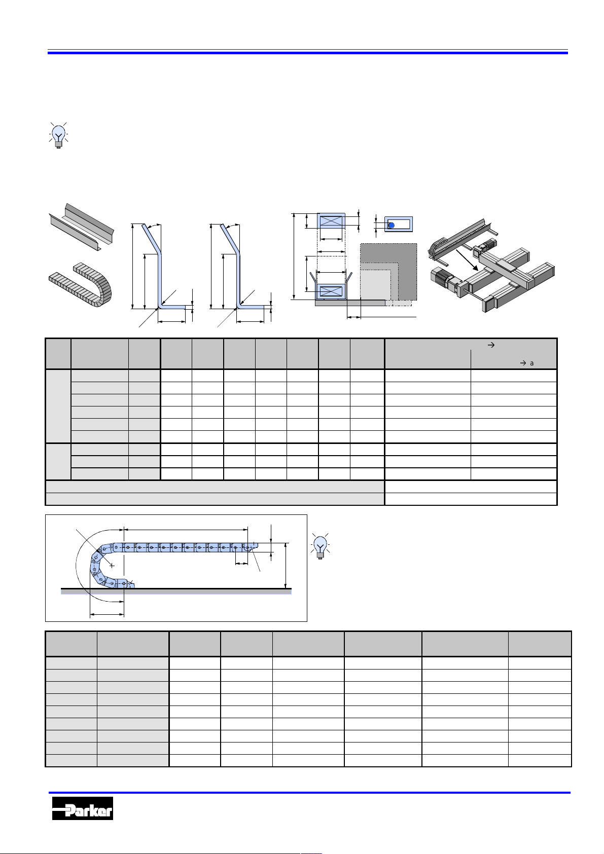
Cable carrier
A cable carrier is needed when making power connections to movi ng elements. The cable carrier chain consi s t s of glass fibre
reinforced polyami de, and the support pr ofile is made of aluminium.
The process for fully determing t he dimensions of a cable carrier is very compl ex. The examples listed below represent
simple applications, but more data will normally be required when the situation is less straightforward.
descriptions only apply to power supplies arranged horizontally, which l ie above a support profil e and whic h
are within the li mits specifi ed in the technical data
. If the applicat ion you are running is more demanding, please
contact us.
Dimensions of support profile and cable carrier cha in
The following
0.320.20 37
0.320.42 37
0.450.21 52
with
0.450.21 94
KSP1
0.450.41 94
0.450.61 150
0.625.25 200
0.625.45 200
with
KSP2
0.625.45 300
KSP1
KSP2
KSP 1
30°
73
48
R2
3
24
R4
Type CR A B C D E F
13 24 29 103 25 19 11 100-906000 100-906100
24 35 40 103 25 19 16 100-905800 100-906110
38 54 59 147 40 24 22 100-905900 100-906090
38 54 59 231 40 24 22 100-906200 100-906090
58 74 79 231 40 24 22 100-906300 100-906095
78 94 99 343 40 24 22 100-906310 100-906350
65 93 98 459 62 42 31 100-906505 100-906506
108 136 141 459 62 42 31 100-906510 100-906506
108 136 141 659 62 42 31 100-906530 100-906506
Small cable support profile (specify length required, equal to travel lenght) 400-010120
Large cable suppo rt pro file (specify length re quired, equal to travel lenght) 400-010121
KSP 2
30°
135
107,1
R4
4
60
R6
E
D
KR
F
A
B
C
d
HLE150
HLEZ150
HLE(Z)100
HLE80
customized
d
max.
(For lengths
Art. no.
Cable carrier chain
page 30)
Æ
2 x connection angle
(for dimensions
page 29)
Æ
KR
B
L
Ü
B
Bending radius Pitch Height Curve length Curve protrusion Connection height Own chain
Type KR
0.320.20 37
0.320.42 37
0.450.21 52
0.450.21 94
0.450.41 94
0.450.61 150
0.625.25 200
0.625.45 200
0.625.45 300
Automation
Fix point
LS/2
Drivin
t h
32 25 181 82 99 0.32
32 25 181 82 99 0.39
45 40 254 117 144 0.75
45 40 386 159 228 0.75
45 40 386 159 228 0.85
45 40 562 215 340 0.92
62.5 62 754 290 456 1.35
62.5 62 754 290 456 1.50
62.5 62 1068 390 656 1.50
G
h
t
G
plate
H
L
28
Dimensional drawings of connection points
(fi x point and driving plate):
Page 29
B
Ü
B
(= 2KR+hg)
H
min
Parker Hannifin GmbH
Electromechanical Division
weight kg/m
Page 29

Dimensional drawings of connection points
Type 0320. xx Type 0450.xx Type 0625. xx
Accessories for HLE and HLEZ
L
K
connection
Standard fix poi nt
L
K
connection
Standard driver
Technical data
Type
40
7
26
40
26
maximum
acceleration
[m/s2]
2
16
2
16
6
A+9
A-16
6
A+9
A-13
arrangement with per-
mitted deflectio n
maximum
stroke
[mm]
3
50 (l1)
7
18,5
15 7,5
35
3
50 (l1)
7
23
15 7,5
35
Self supporting arrangement Self supporting
maximum stroke
[mm]
L
K
A: see dimensions
of cable carrier chain
L
K
A: see dimensions
of cable carrier
chain
maximum speed
[m/s]
7
L
K
9
L
K
maximum speed
[m/s]
63
55
30
35
2
25
94
118
1,5
12,5
10
2
70
25
9
55
30
35
100
1,5
12,5
10
maximum
acceleration
123
[m/s2]
0.320
0.450
0.625
2400 10 10 3500 2.5 1
3000 10 10 4400 2.5 1
5000 8 10 6000 3 1
Guidelines for using cable carriers
Use only electrical cables which are suitable for use in cable carriers. Hose lines should be highly flexible and should
only extend slightly under pressure. Weight should be distr ibuted across the cable track as evenly as possible. Cables
must not be twist ed when routed in the cable carrier and should be routed next to one another and as loosely as possible.
<d
d
electric line
1,1 d
d
hose flat cable
d
1,2 d
d
1,1 d
h
1,1h
Avoid laying several lines on top of each other and laying lines of different diam eters directly next to one another. If mul t i ple layers must be used, separating strips
should be inserted between each layer – should such circumstances arise, please
contact HAUSER.
If there is no alternative to rout ing several lines beside each other without sub-divisions, the clearance height within the carrier m ust be less than li ne diameter.
This is the only way of preventing the cables from twisting.
The supply cables must be able to move freely in the cable carrier – they must
never be fastened or bundled together. Separating strips must al ways be inserted
between flat cables routed in multiple layers.
Recommended di mensions of the space re qui r ed:
with round cables: approx. 10% of the li ne diameter
with flat cables: for each, approx. 10% of the cable width and cable thickness
with hose lines: approx. 20% of the hose diameter
Automation
29
Parker Hannifin GmbH
Electromechanical Division
Page 30

Accessories for HLE and HLEZ
Highly flexible, thin l ines with a low bending strength should be loosely gathered together and routed in order in a protective
hose. When selecting the size of the protective hose, ensure that its area is considerably greater than the sum of t he indi vi dual
cross-sectional areas. As a guide, allow appr oximately 10 % of the diameter of each line as clearance.
Load diagrams
Maximum suspended length vs. additional load Maximum length with permitted deflection vs. additional load
L
S
L
D
additio nal load q
in kg/m
5
0.625
4
3
0.450
2
0.320
1
L
S
L
f
z
additional load q
in kg/m
0.625
5
4
0.450
3
2
1
KR 52 94 150
0.320
z
KR 200 300
KR
0
0123
02
46
suspended length
in m
L
f
stroke L
in m
S
0
0123
0
246
Length with
deflection L
4
Stroke L
8
in m
S
D
in m
Determining the chain length
Suspended chain Chain with permitted deflection
rounded to a multiple of 32 mm
6
/
.
/
%
/
0.320:
rounded to a multiple of 45 mm
0.450:
0.625: rounded to a multiple of 62.5 mm
6
.5/
.
/
%
/
rounded to a multiple of 32 mm
0.320:
rounded to a multiple of 45 mm
0.450:
0.625: rounded to a multiple of 62.5 mm
Longitudinal flange connection set (option V)
Longitudinal f lange plates make it possible to m ove more than the standard avail able stroke. A fl ange connection is al ways
necessary if the maximum travel pat h is exceeded (refer to Technical data, pages 6 and 20). Pr ofil e sections should norm al ly
be split equally, with the separation point cl ose to a fixing point. The bearing dist ance should generally be between 1.0m and
1.5m. I f a l ongitudi nal f lange connection is used to extend the travel distance, the load data must be reduced as shown in the
table below. An HLE with a longitudinal flange connection should only be install ed with the profile aperture in t he top or t he
bottom.
Unit HLE80 HLE100 HLE150 HLEZ100 HLEZ150
maximum permitted load N 0.5 x Fx
Speed m/s < 1 < 1 < 1
Acceleration m/s
Repeatability mm > ±0.5 > ±0.5 > ±0.5
*1. Fx-HLE: refer to p age 7;
2
*1
< 1 < 1 < 1
0.5 x Fx
*1
A
0.5 x Fx
*1
unchanged
Section A-A
FB
A
FL
FD
Model / size Type FL FB FD HB
HLE80 LVS80 300 70 15 80
HLE100 / HLEZ100 LVS100 400 90 15 100
HLE150 / HLEZ150 LVS150 500 130 15 150
Parker Hannifin GmbH
Electromechanical Division
Automation
30
HB
Page 31

Accessories for HLE and HLEZ
Attachment of position sensors and electr onic accessories
Attachment variants for position sensors
Tripping plates, switches and distribution box are attached as standard on the sam e si de as the motor.
The limit switches are fitt ed ensuring that they are ac tivated direct ly before t he st ar t of the standard
safety tr avel ( 125 mm). Unless agreed otherwise, the actuator will be supplied with positi on switches
attached using attachment variant 1 or 2. The tripping plates, swit c hes and di str ibutor sockets are described on page 32.
Variant 1: HL E with 3 integrated proximity swi t ches (standard f or HLE with load attach ment plate)
This sensor attachment is made as standard at the factory. This variant is only possible in the HLEZ, or the HLE c ar r iage
version with bar (T/F/D) and in the corrosion-resistant V2A version (V), if switch lugs are fitted by the customer.
Optional steel strip cover (C) Distribution box
a
=
150
=
b
switch
lug
Schematic drawing
Limit stop Switch lugs Machine origin Limit stop
Standard - HLE HLE with steel strip cover
HLE80 HLE100 HLE150 HLE80 HLE100 HLE150
Dimensions Unit S E S E S E S E S E S E
a
b
mm 187 262 212 287 249 324 232 307 257 332 294 369
mm 171 246 196 271 221 296 216 291 241 316 266 341
Variant 2: HL E or HLEZ wi t h 3 external pro ximity switches
This sensor attachment is made as standard at the factor y for the HLEZ and the HLE ver si ons with bar (T/F/D) and
in the corrosion-resistant V2A version (V).
HLE HLEZ Optional steel strip
cove r (only for HLE)
c
125
Standard safety travel Machine origin Standard safety travel Distribution box
Limit
stop
Drive module
HLEZ
Limit stop HLEZ HLE
d
125
Standard - HLE HLE with steel strip cover HLEZ
HLE80 HLE100 HLE150 HLE80 HLE100 HLE150 HLEZ100 HLEZ150
Dimensions Unit S/T E/F S/T E/F S/T E/F S/T E/F S/T E/F S/T E/F S/T E/F S/T E/F
c
d
The tripping plate is loosely attached in the carriage version with bar (T/F).
mm 223 298 248 323 285 360 268 343 293 368 330 405 248 323 285 360
mm 235 310 260 335 297 372 280 355 305 380 342 417 560 635 737 812
Parker Hannifin GmbH
Electromechanical Division
Automation
31
Page 32

Accessories for HLE and HLEZ
Variant 3: HL E with 2 mechanical end switches and one proximi t y switch
HLE HLEZ Optional steel strip
cove r (only for HLE)
e
Limit
stop
Drive module
HLEZ
Limit stop HLEZ HLE
f
125
Standard safety travel Machine origin Standard safety travel Distribution box
125
Standard - HLE HLE with steel strip cover HLEZ
HLE80 HLE100 HLE150 HLE80 HLE100 HLE150 HLEZ100 HLEZ150
Dimensions Unit S/T E/F S/T E/F S/T E/F S/T E/F S/T E/F S/T E/F S/T E/F S/T E/F
e
f
mm 204 279 229 304 266 341 249 324 274 349 311 386 229 304 266 341
mm 255 330 280 355 317 392 300 375 325 400 362 437 580 655 757 832
The tripping plate is l oosely att ached in t he carri age version with bar ( T/ F) .
Variant 4: HL E with 1 mechanical end switch and 1 proximity switch, bo t h attached to t he moving carriage
This is the preferred variant for robot syst em s if the connections to the switches come via the cable carrier. The tripping pl ates
must be assembled in a m anner which ensures that the mechanical swi t ch i s act uat ed immediately before the start of the
safety travel.
HLE HLEZ Optional steel strip
cove r (only for HLE)
g
125
Standard safety travel Machine origin Standard safety travel
Limit
stop
Drive module
HLEZ
Limit stop HLEZ HLE
h
125
Standard - HLE HLE with steel strip cover HLEZ
HLE80 HLE100 HLE150 HLE80 HLE100 HLE150 HLEZ100 HLEZ150
Dimensions Unit S/T E/F S/T E/F S/T E/F S/T E/F S/T E/F S/T E/F S/T E/F S/T E/F
g
h
mm 270 345 295 370 332 407 315 390 340 415 377 452 295 370 332 407
mm 287 362 312 387 349 424 332 407 357 432 394 469 603 678 780 855
The initiator and t he limit switch ar e loosely att ached in the carri age version with bar ( T/ F).
Tripping plate
Ø4,5
15
Automation
7,5
7
Ø6,5
60
80
90
150
32
2
15
The tripping plate i s suit able for all
standard load attachment plates. It is
°
mounted at the side of the flange
plate using cheese-head screws and
square nuts.
23
25
Parker Hannifin GmbH
Electromechanical Division
Page 33

Accessories for HLE and HLEZ
Mechanical limit switch
The switching but ton complies with DIN EN 50047. The contacts satisfy the safety requirements in ac c or danc e
with EN 60947-5-1 by virt ue of for c ed opening (positively dr iven) .
60
4,4
20
60
51
35
51
85
100
Electrical limit switch
There are two variants of inductive prox imity sensors:
Integrated sensors: These are installed i n a T groove on the upper side of t he pr ofile (standard with flange plate)
External sensors: These are attached to the outside of t he profile (and are used for carr iage ver si on with bar
T/F or for the corrosi on-resistant version V)
The sensors are either activated by a trippi ng plate fastened to the side of the flange plate (ext er nal sensors) or by
a switch lug att ac hed to the underside of the flange plate (integr ated sensors – can only be used for the HLE).
max. 6 5
30
5
Integrat ed sensors:
H
L
LA
B
G
A
S
LED
Model / size A B G H L LA S
HLE80 / HLE100
HLE150
128M4124034 8
128M412524610
Technical data DC electrical data
Switching distance
Switch hysteresis
Repeatability
Ambient te mperature
Type of protection
Cable length
1.8-2.2 m m
3 - 15 %
± 3 %
-25°C - +70°C
IP67
6 m
Connection diagram
bn
bk
bu
Voltage range
Supply current
Maximum switching
current
Voltage drop
Max. swit chi ng f r equency
Connection cables
1
normally closed
2
A
3
PNP-
contact
load
switch
lug
10 - 30 V DC
< 10 mA
150 mA when T = 25°C
< 3.5 V at a switch current of
150 mA
1 kHz
3 x 0.14 mm
2
Automation
33
Parker Hannifin GmbH
Electromechanical Division
Page 34

Accessories for HLE and HLEZ
External sensors:
70
Switching distance
Switch hysteresis
Repeatability
Temperature dr i ft
Ambient te mperature
Type of protection
Cable length
59
26
50
40
Technical data DC electrical data
2mm / 4mm ± 10%
> 1% ...<
0.01 mm
-25°C - +70°C
< 10 %
IP67
6 m
21
6
15
4,4
12
15%
20
5
Connection diagram
bn
bk
bu
Rated voltage
Voltage range
Supply current
Maximum load current
Residual voltage
Max. swit chi ng f r equency
Connection cables
1
normally closed
2
A
3
PNP-
contact
load
24 V DC
10...35 V DC
< 15 mA
300 mA
< 2.5 V DC
2 kHz
3 x 0.25 mm
2
Distribution box
15
20
15
2929
19
20
29
82
22
20
5
80
15
29
20
assembly plate
20
A distri bution box with 2.5 m of c able is attached as standard. If
a different cable length is required, please specify when ordering.
Other accessories and software
DimAxes:
Dimensioning software f or the
HAUSER li near axes (Art. no.: 840-
014400) - for PCs as of Windows
Version 3.xx.
Belt tension measuring device
RSM:
For accurat ely setting the timing belt
tension (Art .no.: 037-000200).
DimAxes
s
e
x
A
im
D
Ini limit
stop 1
normally
closed
contact
Ini machine
origin
normally
closed
contact
Ini limit
stop 2
normally
closed
contact
X3/9
+24V
brown
Sig. E1
black
GND
blue
+24V
brown
Sig. MN
black
GND
blue
+24V
brown
Sig. E2
black
GND
blue
X3/8
X3/7
X2/6
X2/5
X2/4
X1/3
X1/2
X1/1
X4/12
X4/15
X4/14
X4/13
X4/10
distribution
box
+24V
brown
Sig. E1
yellow
Sig. MN
green
Sig. E2
white
GND
blue
DXF/MI f iles on CD-RO M :
CAD fi les of the HLE units. Modular
system for all commonly used CAD
systems
Manual f or using the DXF/MI files
with CD-ROM, Art.nos.:
German: 890-070001
English: 892- 070001
controller
Automation
34
Parker Hannifin GmbH
Electromechanical Division
Page 35

Accessories for HLE and HLEZ
Automation
35
Parker Hannifin GmbH
Electromechanical Division
Page 36

Automation Group
Automation
Parker Hannifin GmbH
Hauser - Elektromechanik
Robert-Bosch-Str. 22
D-77656 Offenburg, Germany
Tel.:+49 (0)781 509-0
Fax:+49 (0)781 509-176
Website: www.parker-emd.com
e-mail: vertrieb@parker-emd.com
Parker Hannifin plc
Electromechanical Division - Digiplan
21 Balena Close
Poole, Dorset. BH17 7DX UK
Tel.:+44 (0)1202 69 9000
Fax:+44 (0)1202 69 5750
Website: www.parker-emd.com
e-mail: sales@parker-emd.com
 Loading...