

Page 1

HLR Mounting Instruction
Electromechanical Automation
The data correspond to the current status at the time of printing.
192-510201N1 HLR
2019-04
HLR Mounting instructions
Operating Manual - Installation, Commissioning, Maintenance and Repair
DOC-0013-02
We reserve the right to make technical changes. 04.04.19 14:29 192-510201N1 HLR 2019-04
Mounting
instructions
Page 2

Introduction HLR Mounting Instruction
2 192-510201N1 HLR 2019-04
Production site:
Par
ker Hannifin Manufacturing Germany GmbH & Co. KG
Electromechanical & Drives Division Europe [EMDE]
Robert-Bosch-Strasse 22
77656 Offenburg, Deutschland)
Tel.: + 49 (0781) 509-0
fax + 49 (0781) 509-98176
Internet: www.parker.com/eme http://www.parker.com/eme
Email address: [email protected] mailto:[email protected]
Parker Hannifin GmbH - registered office: Bielefeld HRB 35489
Management Board: Ellen Raahede Secher, Dr.-Ing. Hans-Jürgen Haas, Kees Veraart - Chairman of the board: Hansgeorg Greuner
Italy:
Parker Hannifin Manufacturing Srl
Electromechanical & Drives Division [EME]
Via C. Gounod, 1
20092 Cinisello Balsamo (Milano), Italy
Phone: + 39 (0)2 361081
Fax: + 39 (0)2 36108400
Internet: www.parker.com/eme http://www.parker.com/eme
E-mail: [email protected] mailto:[email protected]
Non-warranty clause
We checked the contents of this publication for compliance with the associated
hardware and software. We can, however, not exclude discrepancies and do
therefore not accept any liability for the exact compliance. The information in this
publication is regularly checked, necessary corrections will be part of the
subsequent publications.
German Master created.
Page 3

Parker EME
192-510201N1 HLR 2019-04 3
Device assignment
Inhalt
1. Introduction ............................................................................................. 5
1.1 Device assignment .................................................................................. 5
1.2 Type identification plate .......................................................................... 5
1.3 Mounting explanation .............................................................................. 6
1.4 Applications in accordance with the Regulations ................................ 7
1.4.1. Applications not in accordance with the intended use ................................. 7
1.5 For Safety Use .......................................................................................... 8
1.5.1. General hazards ................................................................................................. 8
1.5.2. Identifying Residual Dangers and Hazardous Areas ..................................... 8
1.5.3. Working safely ................................................................................................... 8
1.5.4. Safety Instructions for the Company Using the System ............................... 9
1.5.5. Safety Instructions for Operating Personnel .................................................. 9
1.6 Packaging, storage, transport .............................................................. 10
1.6.1. Special notes on transport ............................................................................. 10
1.7 Terms of guarantee / warranty .............................................................. 11
1.8 Conditions of utilization ........................................................................ 12
2. Device description ................................................................................ 13
2.1 Technical data ........................................................................................ 16
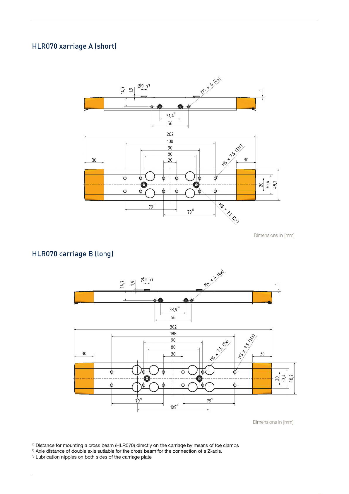
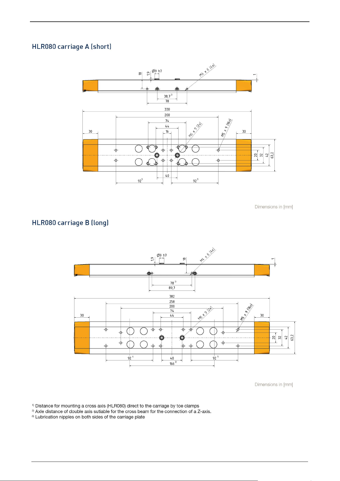
2.2 Dimensions ............................................................................................. 17
3. Mounting ................................................................................................ 20
3.1 General installation instructions .......................................................... 20
3.2 Installation of a single axis ................................................................... 21
3.3 Mounting Method of a double axis ....................................................... 22
3.3.1. Alignment of a double axis ............................................................................. 22
3.3.2. Installation of connection shaft...................................................................... 24
3.4 Correct position of loads on the carriage. ........................................... 26
3.5 Installation / dismantelling of the drive ................................................ 27
3.6 Assembly of Z-axes ............................................................................... 28
3.6.1. Mounting ETH/ETT032 on single axis via bracket plate .............................. 29
3.6.2. Mounting ETH/ETT032 & ETH/ETT050 on double axis via cross beam ..... 31
3.6.3. Assembly of OSP-E20BV to single axis via mounting plates ..................... 33
3.7 Assembly of accessories ...................................................................... 34
3.7.1. Sensors ............................................................................................................. 34
3.7.2. External end stops ........................................................................................... 36
4. Commissioning ..................................................................................... 37
4.1 General notes on commissioning ........................................................ 37
4.2 Use at elevated ambient / operating temperatures ............................. 38
5. Maintenance and service ...................................................................... 39
5.1 General maintenance notes .................................................................. 39
5.2 Maintenance schedule and replacement intervals .............................. 40
5.3 Lubrication of the guiding system ....................................................... 41
Page 4

Introduction
HLR Mounting Instruction
4 192-510201N1 HLR 2019-04
5.4 Steel strip cover disassembly and replacement ................................. 43
5.5 Toothed belt ........................................................................................... 45
5.5.1. Checking and setting toothed belt tension ................................................... 45
5.5.2. Exchanging the toothed belt .......................................................................... 47
5.6 Replace carriage lid ............................................................................... 49
5.7 Check steel strip deflectors and steel strip sliding rods .................... 50
5.8 Exchange guiding system ..................................................................... 50
5.9 Spare and Wear Parts ............................................................................ 51
5.9.1. Wear parts ........................................................................................................ 51
5.9.2. Spareparts ........................................................................................................ 51
6. Supply repair ......................................................................................... 52
7. Index ....................................................................................................... 53
Page 5

Parker EME
192-510201N1 HLR 2019-04 5
Conditions of utilization .................................................................................................... 12
Manufacturer address
PN:
Order code
SN:
Unambiguous identification number
Tested:
Date of factory test
1. Introduction
In this chapter you can read about:
Device assignment ............................................................................................................ 5
Type identification plate ..................................................................................................... 5
Mounting explanation......................................................................................................... 6
Applications in accordance with the Regulations ................................................................ 7
For Safety Use .................................................................................................................. 8
Packaging, storage, transport .......................................................................................... 10
Terms of guarantee / warranty ......................................................................................... 11
1.1 Device assignment
This manual applies for the following devices:
Linear actuators with the designation:
HLR070
HLR080
i
Device assignment
1.2 Type identification plate
Type specification plate (example)
Type specification plate explanation
Page 6

Introduction
HLR Mounting Instruction
6 192-510201N1 HLR 2019-04
1.3 Mounting explanation
Page 7

Parker EME
192-510201N1 HLR 2019-04 7
Applications in accordance with the Regulations
1.4 Applications in accordance with the Regulations
The incomplete machine can only be set in operation if it is sure that the machine
in which the incomplete machine shall be mounted is conform to the 2006/42/EG
machine directives.
Without further measures the product is not suitable for safety-oriented tasks. The
linear actualor must only be used in areas that are not accessible to persons during
operation.
If the linear actuator is used in areas accessible to people, it must be installed in
such a manner that no one can be endangered during operation.
The described safety, installation and operating instructions must be adhered to.
General functioning consists in converting a rotational movement in a linear
movement without slip within the product related load limits.
Can be found here (see page 16) and in the HLR Catalogue
(http://www.parker.com/eme/hlr).
Its applications are in industry and trade.
The linear actuator is used for: Positioning, transporting, feeding, removing, pallet
handling, loading, unloading, processing and manipulating as well as testing work
pieces or tools. Since the component can be used in a very wide range of
applications, the user is responsible for its use in specific applications.
1.4.1. Applications not in accordance with the intended use
For risks of applications not in accordance with the intended use, the user shall
bear the sole responsibility. Parker Hannifin does not accept any liability for
damages caused by applications not in accordance with the intended use of the
product.
Page 8

Introduction
HLR Mounting Instruction
8 192-510201N1 HLR 2019-04
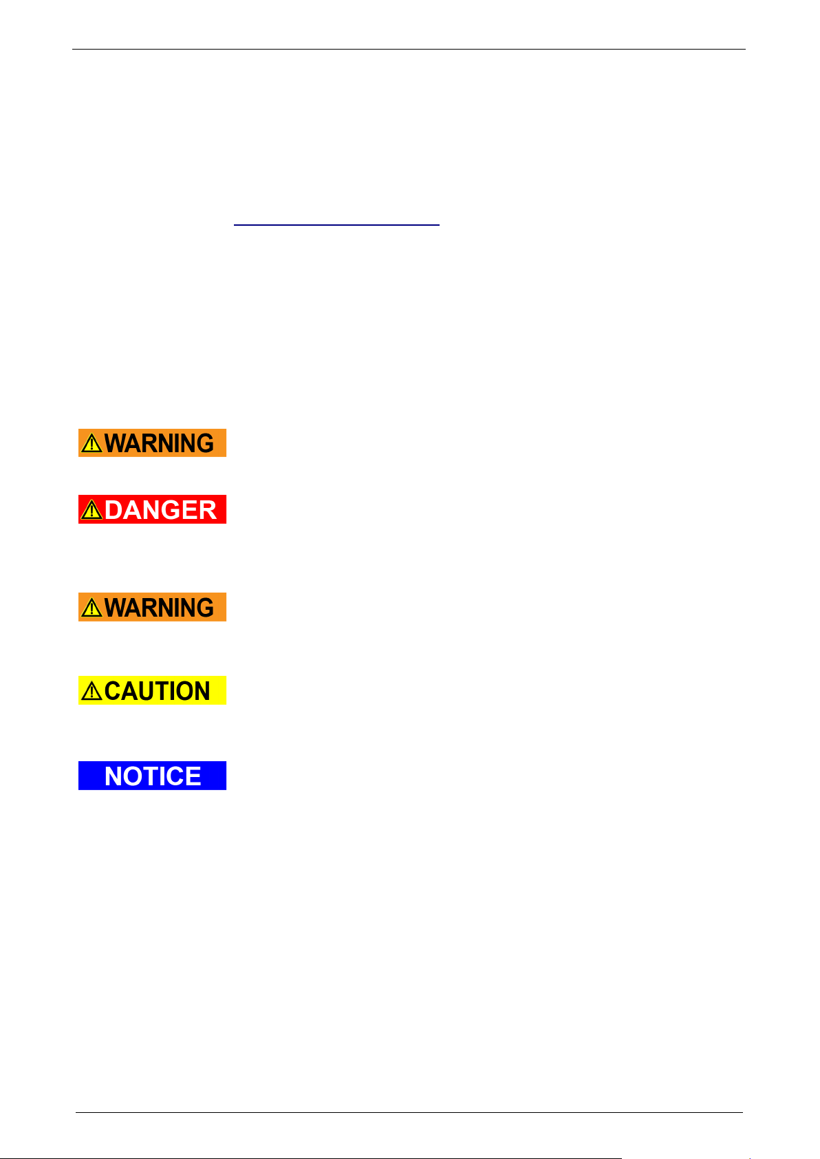
Indicates a potentially hazardous situation which, if not avoided using appropriate
safety measures, could result in serious or minor injury.
Provides important information about the product, how to handle the product or
about the part of the manual to which particular attention must be paid.
The information (such as instructions and notes) contained in this manual must
condition.
1.5 For Safety Use
1.5.1. General hazards
General Hazards on Non-Compliance with the Safety Instructions
The subsystem has been designed in accordance with state-of-the-art technical
developments and is operationally reliable. If it is not operated by qualified or at
least trained personnel or if it is operated improperly or not in accordance with the
operating instructions, however, the unit may bear the risk of hazards.
Electronic, moving and rotating components can
cause danger for life and limb of the operator or third persons and / or
cause material damage
.
If the linear actuator is installed in a machine plant, the safety requirements noted
i
n the operating instructions for that machine must be combined with thos
des
cribed in this manual.
1.5.2. Identifying Residual Dangers and Hazardous Areas
If there are still residual dangers present to persons or property from the linear
actuator in spite of operating it in a safe manner, the user must make reference to
these residual dangers through signs and written rules requiring appropriate
procedures.
The following safety signal words are used:
e
Indicates that an imminent hazardous situation may lead to death or serious
bodily harm if not prevented using appropriate safety measures.
Indicates a potentially hazardous situation which, if not avoided using appropriate
safety measures, may result in minor injury or material damage.
1.5.3. Working safely
be heeded for all work involved in installing, commissioning, setting up, operating,
changing operating conditions and modes, servicing, inspecting and repairing the
unit.
The manual must be available close to the linear module during the performance
of all tasks.
It is impermissible to operate the liner module if it is not in perfectly functional
Operating personnel
Only qualified expert personnel is permitted to perform works on the linear
actuator. All the applicable regulations and provisions must be heeded (IEC, EN,
national accident prevention regulations etc.).
Qualified persons as the term is used in this manual are persons who:
persons who, by virtue to their training, experience and instruction, and their
knowledge of pertinent norms, specifications, accident prevention regulations and
operational relationships, have been authorized by the officer responsible for th
afety of the system to perform the required task and in the process are capabl
s
recognizing potential hazards and avoiding them (definition of skilled persons
of
in accordance with VDE015 or IEC364)
e
e
Page 9

Parker EME
192-510201N1 HLR 2019-04 9
with safety transmitter switches.
Supervisors must also become familiar with the entire chapter entitled "Safety"
devices.
Any work step that has a negative effect on the operating safety of the linear
always be observed when installing and operating our linear motor module.
For Safety Use
Persons who have a knowledge of first-aid techniques and the local emergency
rescue services.
Persons who have read and will observe the safety instructions.
Instructions for Special Hazards
The linear module must be fixed or supported in accordance with the indications
in this manual.
The operator must ensure that operation of the linear module does not cause any
danger.
If the linear module moves in hazardous areas, these areas must be safeguarded
1.5.4. Safety Instructions for the Company Using the System
and handling required on the linear actuator.
Supervisors must ensure that installation and operating personnel have read and
understand the chapter entitled "Safety" and the description of how to work with
the machine, and that they observe the instructions.
The manual must be available close to the linear module during the performance
of all tasks.
It is impermissible to operate the liner module if it is not in perfectly functional
condition.
Depending on the application, the operating company must provide for a suitable
separating safety fence. Access to the motion range during operation must be
prevented.
The user must make sure that the work area is protected by appropriate safety
1.5.5. Safety Instructions for Operating Personnel
motor module must be omitted.
Operating and supervisory personnel are required to check the linear actuator or
machine at least once per shift for externally visible damage or defects. Changes
that have occurred (including the operating behavior) that could have a negative
effect on the operating safety must be reported immediately.
Components and accessories are designed especially for this product. When
purchasing spare and wear parts, use only original Parker parts. We explicitly
draw your attention to the fact that we are unable to check or release spare parts
or accessories that were not provided by us. Installing and/or using such products
may cause negative changes in the required design properties in some
circumstances, which in turn could negatively effect the active and/or passive
operating safety of the product.
The manufacturer is unable to accept any liability for damage caused by using
non-original parts and accessories.
Depending on the operating conditions (rotation speed, load, etc.) increased
surface temperature in the area of the drive may occur. When touching it during
operation slight injuries from burning may occur. Don't touch the product during
operation. At maintenance, service and repair always take care that the product is
cooled off before starting work.
Safety and protection devices are strictly NOT to be removed or bypassed or set
out of order.
Applicable requirements and national accident prevention regulations must
Page 10

Introduction
HLR Mounting Instruction
10 192-510201N1 HLR 2019-04
The packaging material is inflammable, if it is disposed off improperly by burning,
lethal fumes may develop.
suitable for
recycling
Metal
Plastic materials
Never step under overhead loads danger of being injured!
Moving parts must always be secured against slipping or moving.
1.6 Packaging, storage, transport
First check
Check the packaging for damages.
Remove all items from the packaging.
Do not discard the packaging; it is strongly recommended to use the original
packaging material for return deliveries.
Depending on the storage location, metal surfaces may have a temperature of
0 °C or below. Please provide appropriate worker protection (e.g. protectiv
gl
oves).
Please ensure that the consignment does correspond to your order.
Check the product for damages. Do never use a device which seems damaged.
Please read the installation manual carefully before installing or commissioning
t
he device.
Packaging material
e
Transport
Make sure to transport the linear module always in a safe manner and with the aid
of suitable lifting equipment (Means of transport).
Storage
The linear module must be stored evenly and without any mechanical load.
The stated storage temperature must be adhered to.
For a storage period longer than 1 year, the linear module must be relubricated
before commissioning.
Disposal
We recommend to dispose off the respective materials in accordance with the
respectively valid environmental laws. The following table states the materials
suitable for recycling and the materials which have to be disposed of separately.
Material
yes no
yes no
1.6.1. Special notes on transport
When using ropes, make certain they are not twisted or knotted. If you are using
more than one rope, all the ropes should be equally taut.
When transporting the cylinder with a forklift, establish an equilibrium and secure
the load if necessary.
Disposal
Use only transport equipment with sufficient lifting capacity. Take care of
structural safety when using lifting equipment!
In general, no means of transport are needed for the linear actuator. Depending on
its size, the linear actuator can be carried by one or two persons.
Page 11

Parker EME
192-510201N1 HLR 2019-04 11
1.7 Terms of guarantee / warranty
These operating instructions are subject to changes including changes in technical
details with respect to the information and figures contained herein.
Parker Hannifin Manufacturing Germany GmbH & Co. KG grants no quality or
durability guarantees nor any guarantees as to the suitability for specific purposes.
Such guarantees must be expressly agreed upon in writing
Public statements, recommendations or advertising do not in any way represent
quality specifications.
The warranty rights of the user imply that he reports any fault immediately and
describes it precisely in his notice of defects. Parker Hannifin Manufacturing
Germany GmbH & Co. KG is not responsible under any circumstances for damage
to the product itself or any consequential damage caused by the product resulting
from improper handling of the product. If Parker-Hannifin Manufacturing Germany
GmbH & Co. KG is responsible for a defect, Parker-Hannifin Manufacturing
Germany GmbH & Co. KG shall be authorized, at its discretion, to undertake
improvements or deliver replacements.
In compliance with ISO 9000, all products are equipped with a type plate and a
note of care that are bound to the device. The type plate must not be removed or
damaged under any circumstances.
Parker Hannifin Manufacturing Germany GmbH & Co. KG shall not be held liable,
regardless of any legal basis, except for cases of intent or gross negligence;
injuries to life, body or health; or defects of malicious nondisclosure or whose
absence was expressly guaranteed in writing.
Furthermore, if there is compulsory liability under the Product Liability legislation for
personal injury and property damage to privately used objects, in the event of
negligent breach of significant contractual obligations, Parker Hannifin
Manufacturing Germany GmbH & Co. KG shall also be liable for cases of ordinary
negligence; however, this is limited to damages that are contractually typical and
foreseeable.
Further claims are hereby excluded.
The warranty shall lapse in the event of non-compliance with these operating
instructions, the relevant statutory provisions and other information provided by the
supplier.
In particular, we are not responsible for failures caused by modifications made by
the customer or other parties. In such cases, the normal repair costs will be
calculated. These costs will likewise be calculated for a check of the unit if no fault
can be determined on the unit.
This regulation also applies during the warranty period.
No claims exist as to the availability of previous versions or to the retrofitting
capacity of the units delivered to adapt them to the respectively current model
version.
Terms of guarantee / warranty
User conversions and changes are not Permitted
The linear actuator must not be changed in its design or in terms of safety without
our approval. Any change as defined here made by the user excludes any liability
on our part.
Page 12

Introduction
HLR Mounting Instruction
12 192-510201N1 HLR 2019-04
The operation of the linear actuator is only permitted within the range of the limit
or even damages must be expected.
Even if the limit switches were already mounted at our premises, they must be
adapted according to suitable values before operation!
Always use all available mounting possibilities and respect the requirements.
The internal end stops serve as damping element during mechanical collision.
However, they can avoid limited damages only.
1.8 Conditions of utilization
General introductory notes
With this linear actuator, you bought a product which was manufactured and tested
before delivery with the utmost care.
Please take your time to read the following notes which you ought to follow closely
during setup and operation.
values stated in this manual (technical data).
Unless, all claims under the warranty will become void and a reduced service life
P
lease compare the operating data with the stated limit values especially
with reference to:
Stroke length and setting of the limit switches, those must be set so that there is a
sufficient safety distance at both ends of the stroke
Velocity
Acceleration
Loads
Process forces
Environmental conditions (e.g. temperature, dirt)
Please do take possible pulses caused by moved masses into consideration for
the operating data.
Note on the installation of the linear actuator
If the motor used with the linear actuator should be able to exceed individual limit
values, the respective values for the motor must be limited in the control by
appropriate parameterization. The parameterization should even be reduced to the
values necessary for operation.
The service life of the linear actuator is strongly dependent on the extent to which
its performance capability is exhausted and whether - even if only for a short period
of time - inadmissible operating states have occurred.
Page 13

Parker EME
Conditions of utilization
192-510201N1 HLR 2019-04 13
Dimensions ...................................................................................................................... 17
2. Device description
In this chapter you can read about:
...................................................................................................................................... 13
Technical data ................................................................................................................. 16
Page 14

Device description
HLR Mounting Instruction
14 192-510201N1 HLR 2019-04
Page 15

Parker EME
Conditions of utilization
192-510201N1 HLR 2019-04 15
Page 16

Device description
HLR Mounting Instruction
16 192-510201N1 HLR 2019-04
2.1 Technical data
Page 17

Parker EME
192-510201N1 HLR 2019-04 17
2.2 Dimensions
Dimensions
Page 18
Device description
HLR Mounting Instruction
18 192-510201N1 HLR 2019-04
Page 19
Parker EME
Dimensions
192-510201N1 HLR 2019-04 19
Page 20
Mounting
HLR Mounting Instruction
20 192-510201N1 HLR 2019-04
Assembly of accessories ................................................................................................. 34
Before carrying out any installation work make sure that carriage cannot move.
carriage.
Before carrying out any installation work de-energize the motor. Danger of
the motor used.
Always ensure that the carriage is secured against slipping, especially when the
vertical position is reached.
Depending on the operating conditions (rotation speed, load, etc.) increased
operation.
When installing the HLR linear axes in your system, make sure that the deflection
Loctite242)
3. Mounting
In this chapter you can read about:
General installation instructions ....................................................................................... 20
Installation of a single axis ............................................................................................... 21
Mounting Method of a double axis ................................................................................... 22
Correct position of loads on the carriage. ......................................................................... 26
Installation / dismantelling of the drive ............................................................................. 27
Assembly of Z-axes ......................................................................................................... 28
3.1 General installation instructions
Therefore, de-energize the respective drive and mechanically secure the
electrical voltage. Improper wiring may lead to severe injuries or death. A wiring
must always be made from a skilled electrician.
Observe the safety instructions of
linear actuator is mounted vertically! For this purpose, push the carriage slowly by
hand to the (later) lower position against the internal end stop, even before the
surface temperature in the area of the drive may occur. When touching it during
operation slight injuries from burning may occur.
Don't touch the product during
stations and the carriage are accessible for maintenance purposes! Provide
sufficient space to lubricate the carriage and the deflection stations regularly, to
replace the wear parts and, if necessary, to tighten or replace the toothed belt
and, if necessary, to open or replace the steel strip cover.
Before installation, check the supplied linear actuator for compliance with the
order confirmation, see order code on the type plate of the linear axis (complete
specification of the actuator).
We recommend to secure the screws with a liquid bolt retaining compound (e.g.
Page 21
Parker EME
192-510201N1 HLR 2019-04 21
Linear actuators must be sufficiently fastened to the surrounding
mentioned below are mandatory.
Bends or deformations on the linear axis due to excessive loads / weights, too
expected service life of linear actuators.
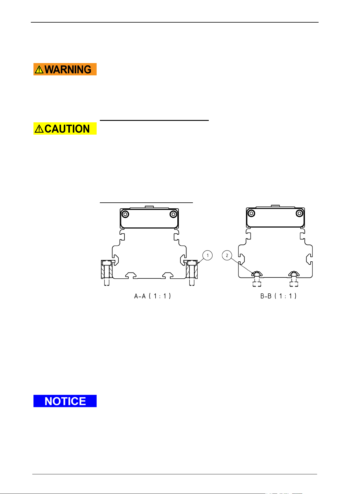
3.2 Installation of a single axis
Installation of a single axis
construction/substructure. Not sufficiently fastened linear actuators may shift,
slide and may cause considerable damage and injuries.
Do only use the appropriate mounting parts mentioned in the installation
instructions for the respective mounting methods.
The torque moments
Requirements for substructzre devices
large support distances or uneven substructure devices should be avoided as
much as possible. Substructure which do not meet the requirements may cause
internal tension to the linear actuators and the guiding system.
This may reduce
The HLR linear axis should be supported as consistently as possible on leveled or
machined connection surfaces:
Flatness of the connection surfaces: ≤ 0.2 mm/m
permissible max. bend deflection of the axis: see HLR catalogue
Connection options for mounting
To fasten the linear axis to the substructure device, one groove is provided on
each side of the support profile and two grooves on the underside.
For the installation of the lateral grovves, two toe clamps are optionally available
(please refer to Figure 1, Pos. 1). For the installation of the grovves on the
underside, two slot nuts are optionally available (please refer to Figure 1, Pos. 2
Please refer to accessories in the HLR catalogue.
The linear actuator must be fixed at at least two points along the carrier profile.
Additional mounting points are recommended for linear actuators with longer
stroke lengths and high loads.
Either two toe clamps (left and right on the carrier profile) or 4 slot nuts (two for
each lower groove) are required for each fastening point, see Figure 1.
For dimensions of the HLR linear actuator, hole pattern of the mounting options
and recommended support distances, see HLR catalogue.
Depending on installation conditions and space conditions in the plant, it may be
more advantageous to mount the drive to the linear actuator before installation; see
chapter installation/ dismantelling of the drive (see page 27).
Installation of a single axis
Figure 1: installation options
Page 22

Mounting
HLR Mounting Instruction
22 192-510201N1 HLR 2019-04
Screw type [ISO 4762]
-
M5 - 8.8
Installation of connection shaft ......................................................................................... 24
Improper installation of parallel working linear actuators may cause internal
installation may negatively affect operational behaviour and system accuracy.
Place the second linear actuator on the leveled connection surfaces. If fixing with
slot nuts, position the slot nuts accordingly in the profile beforehand.
For lubrication of the internal guide, lubrication access points are provided on
both sides of the carriage.
Rough alignment of the actuator with the system (alignment with the mounting
holes of the selected connection option).
Place the toe clamps on the fixing points and screw in the screws (screw in
screws completely and loosen them approx. half a turn to allow adjustment of the
axis).
Final alignment of the linear actuator to the system (position and parallelism of
the linear actuator). Depending on the required accuracy, a measuring tape,
distance gauges, dial gauge or other suitable measuring equipment can be used.
Tighten screws with the respectable tightening torque (see Table 1).
Check alignment of the linear actuator to the system.
Tightening torque of clamp collar
HLR070 / HLR080
Tightening torque*
Table 1: tightening torques toe clamps
*The required tightening torque can vary depending on application conditions, substructure devices and tightening and screwing
procedures and must be defined by the customer in individual cases.
The assembly of the single actuator is completed.
For mounting attachments such as drive, limit switches or loads on the slider, see
the following chapters.
3.3 Mounting Method of a double axis
In this chapter you can read about:
Alignment of a double axis ............................................................................................... 22
3.3.1. Alignment of a double axis
tension which will significantly reduce lifetime. Furthermore, an improper
Requirements for substructure devices
In addition to the requirements for the single axis, as described in the
chapterinstallation of a single axis (see page 21), the following requirements also
apply to the substructure device for double axis applications.
Flatness of connection surfaces: ≤ 0.2 mm/m (to all adjacent contact surfaces in x
and y direction)
Max. permissible axis parallelism: ≤ 0.025 mm (ovr the entire stroke)
[Nm] 5.0
Page 23
Parker EME
192-510201N1 HLR 2019-04 23
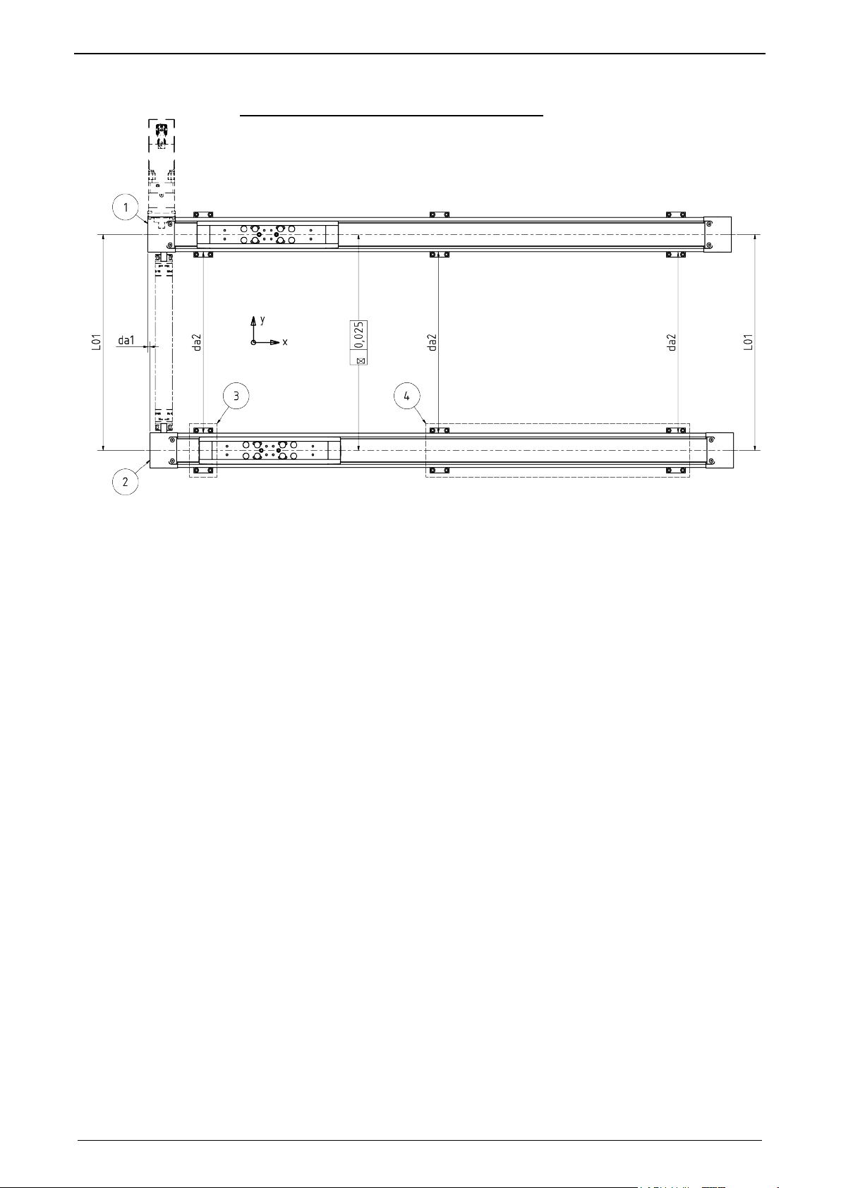
Installation process of a double-axis actuator
Mounting Method of a double axis
Figure 2: alignment double axis
Installation of the first (driving) Linear actuator (Figure 2, Pos. 1) as described in
chapter Installation of a single axis (see page 21)
Place the second (driven) linear actuar (Figure 2, Pos. 2) to the leveled or treated
connection surfaces. Rough alignment of the axis with the system (alignment with
the mounting holes of the selected connection option). If the shaft trunions for
mounting the connection shaft are already pre-assembled, make sure that the
shaft trunions are oriented towards each other.
Place the toe clamps on the fixing points and screw in the screws (screw in
screws completely and loosen them approx. half a turne to allow adjustment of
the axis).
Check center distance of the double axis (Figure 2 und Table 2, measurement
L01) and correct if necessary.
Align the linear axes axially to each other. Use the front faces of the drive
stations. Maximum permissible offset of the drive stations (Figure 2,
measurement da1): (L01-158) * tan0.06.
Tighen the screws of the first fastening point of the second linear actuator (Figure
2, Pos. 3) with the respective tightening torque (please refer to Table 1).
For the parallel alignment of the double axes, set the same distances one after
the other between the individual fixing points of the linear actuators(Figure 2,
measurement da2) and tighten the screws of the fastening points of the second
linear actuator (Figure 2, Pos. 4) with the respective tightening torquen (please
refer to Table 1). Observe the maximum permissible axis parallelism ≤ 0.025 mm.
For this, use stops/stop edges, distance gauges, a dial gauge or other suitable
measuring equipment.
Recommendation: Checking the alignment of a double axes
Push both carriages to the delfection station intended for mounting the
connection shaft.
Mechanically connect the carriage of the double axes. Use mounting threads in
the carriages and observe the requirements to the installation surface of the
mechanical connection, see chapter mounting loads on the carriage (see page
26).
Move both carriages simultaneously to the first clamping point.
Loosen the clamping point of the second (driven) linear actuator and tighten
again the clamp position to the required tightening torque.
Perform this procedure at each clamping point of the second (driven) linear axis.
Page 24
Mounting
HLR Mounting Instruction
24 192-510201N1 HLR 2019-04
During operation it is not allowed to grap in the working area of the connection
shaft against accidental grapping.
Connections shaft can compensate axial, radial and angular deviations. All
application data of the double axis must lie within the technical specifications.
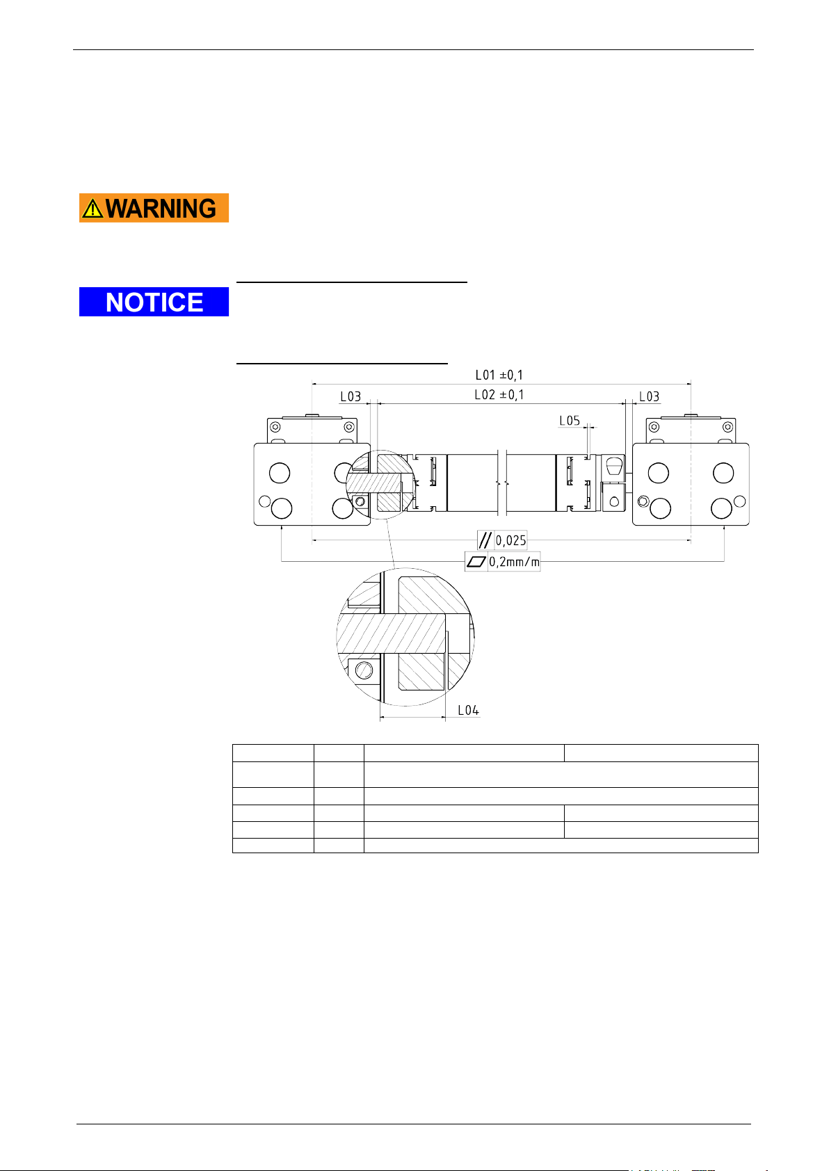
HLR070
HLR080
L01 ±1.0
Center distance; (please refer to part number Connecting shaft: Ex.
0242.910-0500, L01=500mm)
L02 ±1.0
[mm]
L01 – 92 mm
L03
[mm]
11.5
5.0
L04
[mm]
29.3
23.0
L05
[mm]
2
3.3.2. Installation of connection shaft
Purpose of connection shafts is the force transmission of parallel connected linear
actuators. Connection shafts including fixing material are available as accessories
in the HLR catalogue.
shaft. Moving parts may cause severe injuries. Protect work area of connection
Technical Data of connection shaft
Dimensions of connection shaft
[mm]
Table 2: dimensions of connection shaft
Figure 3: dimensions of connection shaft
Page 25
Parker EME
192-510201N1 HLR 2019-04 25
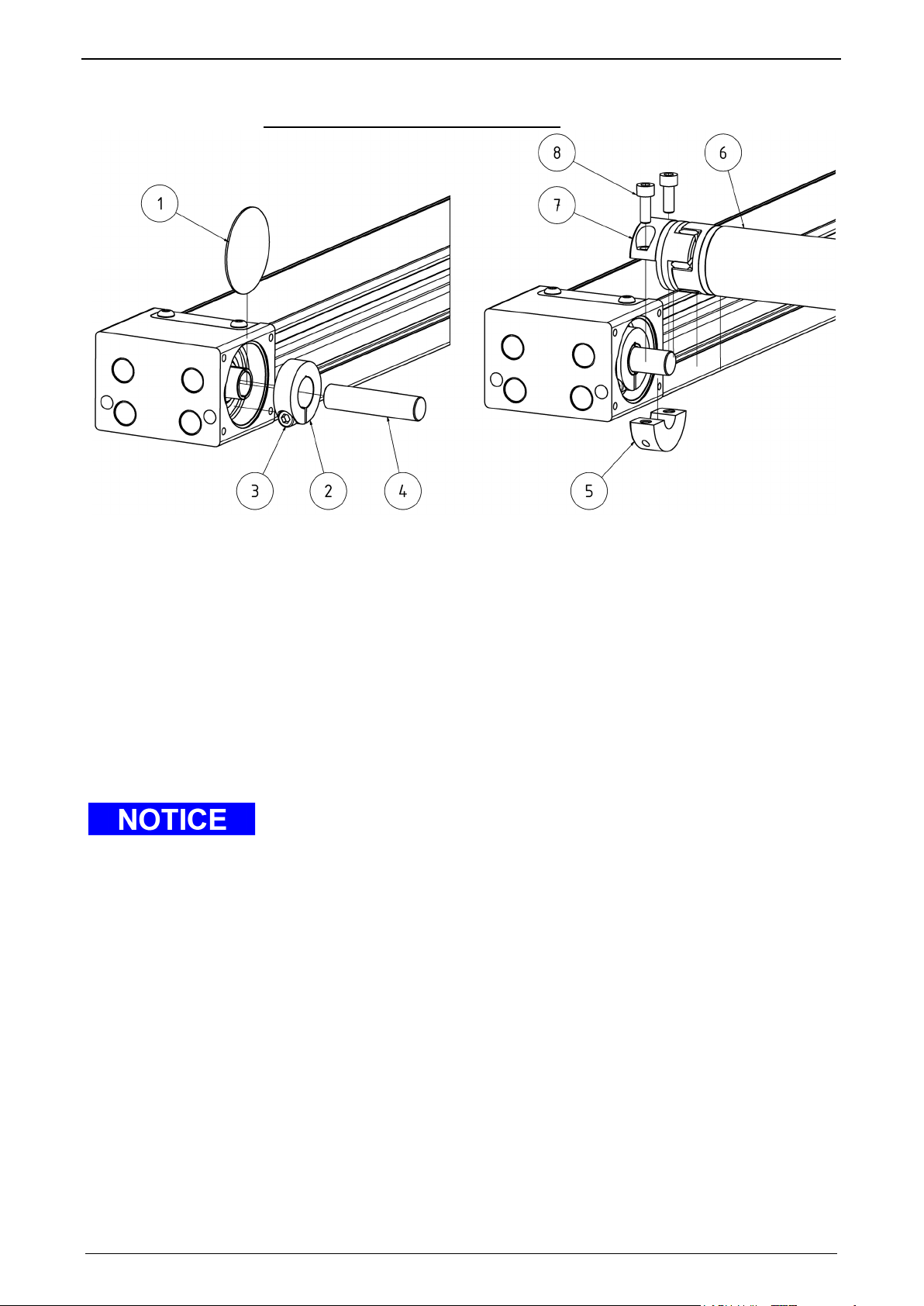
Clamp collar must abut to the pulley shoulder. The slot in the clamp collar must
be aligned to the slot in the pulley. Please refer to (Figure 5 detailled view A.)
Assembly sequence of connection shaft
Mounting Method of a double axis
Figure 4: assembling sequence of connection shaft
Both double axes are mounted according to the chapter alignment of a double
axis (see page 22).
Axes are aligned parallel to each other, shaft trunions are aligned and axes are
aligned parallel and axial to each other (permissive deviations see Figure 3).
The following working steps need to be carried out on both linear actuators, at the
respective opposite deflection stations.
Remove protection caps (see Figure 4, Pos. 1) of the respective deflection
station.
Pull clamp collar (please refer to Figure 4, Pos. 2) incl. clamping screw (please
refer to Figure 4, Pos. 3) onto the pulley. The clamping surface between pulley
and clamp collar must be free of oil and grease.
Adjust clamp collar (please refer to Figure 4, Pos. 2) and pulley. Manually push
carriage so that the clamping screw (please refer to Figure 4, Pos. 3) is
accessible through the front mounting bore of the deflection station.
Insert shaft trunions (see Figure 4, Pos. 4) into the pulley and adjust the excess
length L04 (see Table 2, Figure 4). Clamping area between pulley and shaft
trunions must be free of oil and grease!
Tighten the clamp collar to the required tightening torque using the clamping
screw on the face side through the bore of the deflection station (see Table 3).
Remove the clamping halves (see Figure 4, Pos.5) of the connection shaft on
both sides.
Check distance between the connection shaft (see Figure 4, Pos.6) and the
coupling halves (see Figure 4, Pos.7) and readjust in the event of deviation (see
Table 2, Figure 3 measurement L05).
Clean clamping areas of the connection shaft (tension halves and coupling
halves) and shaft trunions (free of oil and grease).
Align the carriages of the double axes with each other.
Recommendation: Push both carriages to the internal stops of the drive stations
with the mounted shaft trunions.
Page 26
Mounting
HLR Mounting Instruction
26 192-510201N1 HLR 2019-04
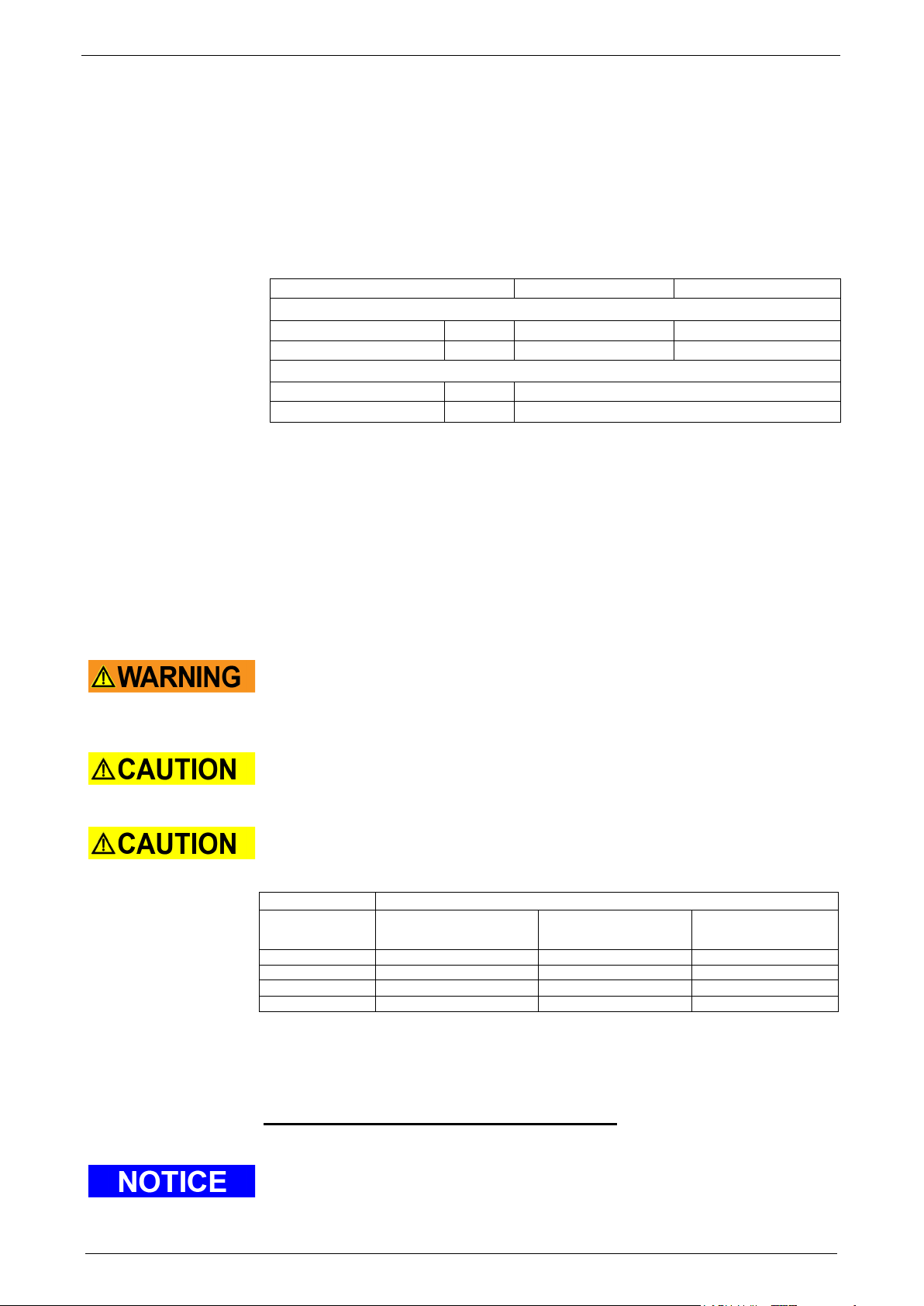
HLR070
HLR080
Screw type [ISO 4762]
-
M5 x 14 – 10.9
M6 x 20 - 10.9
Tightening torque
[Nm]
6.0
15.0
All loads mounted to the carriage must be securely safed against shifing and
The torque moments mentioned below are mandatory.
The thread depth of the mounting bore in the carriage may not be exceeded.
carriage.
HLR070 & HLR080
Thread size
[mm]
[mm]
[Nm]
M4
4.0/6.0
3.5
2.5
M5
7.5/9.0
6.0
5.0
M6
7.5/9.0
6.0
7.5
Place the connection shaft (see Figure 4, Pos.6) on the shaft trunions and
mediate between the linear axes. Check distance between deflection stations and
connection shaft on both sides (see Table 2, Figure 4, measurement L03).
Place tension halves of the connection shaft (please refer to Figure 4, Pos. 5) and
slightly tighten with the clamping screws (please refer to Figure 4, Pos. 8).
Tigthen clamping screws in such a way that an equal-sized slot between coupling
halves and tension halves turns up.
Alternately tighten the clamping screws to the respective tightening torque
(please refer to Table 3).
Tightening torque clamp collar (please refer to Figure 4, Pos. 3)
Tightening torque connection shaft (please refer to Figure 4, Pos. 8
Screw type [ISO 4762] M6 x16 – A2-70
Tightening torque [Nm] 7.4
Table 3: Tightening torques and screws of the connection shaft
3.4 Correct position of loads on the carriage.
Standar carriages of HLE linear actuators have various mounting threads for the
connection of loads, cross beams or Z-axes.
Existing centering sleeves integrated into the carriage can be used to align the
load.
Position of mounting threads and centering sleeves and depth see dimensions (see
page 17).
sliding. Not sufficiently fastened linear actuators may shift, slide and may cause
considerable damage and injuries.
Failure to comply with this may result in a breakthrough and damage to the
If the specified tightening torques are exceeded, there is a risk of damage to the
threads.
Present screw-in depth*
HLR070 / HLR080
Recommended screw-in
depth*
Tightening torque**
Table 4: Anzugsmomente mounting thread of the carriage
* Maximum present thread depth may not be exceeded.
** Recommended tightening torque valid for the recommended srew-in depth. Depending on screw-in depth, application boundary
conditions and tightening/ screwing procedure, the tightening torque may vary and must be defined by the customer in individual cases.
Installation surface requirements of the payload
Flatness of the installation surface of the payload ≤ 0.05 mm
When the centering sleeves for mounting the load are an obstacle, they can be
carefully pulled out with a pair of needle-nose pliers.
Page 27
Parker EME
192-510201N1 HLR 2019-04 27
As standard, the HLR Linear actuators are equipped without drive flange. For the
accessories in the HLR catalogue).
Installation / dismantelling of the drive
3.5 Installation / dismantelling of the drive
Before mounting or dismantelling the motor, de-energize it.
gear attachment, one of the optionally available flange kits is needed (see
For dismantelling, the assembling sequence has to be carried out in reverse order.
Assembling sequence
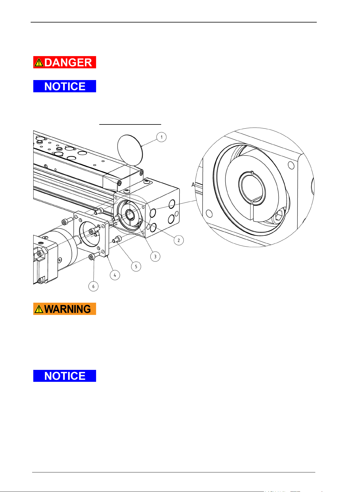
Figure 5: Assembly of drive
Requirement: Axis is mounted in the system or fastened to another basic
structure.
Remove protection caps (see Figure 5, Pos. 1) of the respective side of the
deflection station.
Push clamp collar (please refer to Figure 5, Pos. 2) incl. clamping screw (please
refer to Figure 5 Pos. 3 onto the pulley. The clamping surface between pulley and
clamp collar must be free of oil and grease.
Clamp collar must abut to the pulley shoulder. The slot in the clamp collar must
be aligned to the slot in the pulley (see Figure 5 detailled view A).
Adjust clamp collar (please refer to Figure 5, Pos. 2) and pulley. Manually push
carriage so that the clamping screw (please refer to Figure 5, Pos. 3) is
accessible through the front mounting bore of the deflection station.
Pre-assemble drive package (motor with gears). Please observe operating
instructions/ manual of motor and gearbox.
Clean drive shaft and drive flange from anti corrosion agents, grease and oil.
Mount the HLR gear flange (see Figure 5, Pos. 4) to the gear output side using
the gear screws (see Figure 5, Pos. 5). For screws please refer to Table 5.
Page 28
Mounting
HLR Mounting Instruction
28 192-510201N1 HLR 2019-04
Please take care that the carriage will not be moved during the installation of the
the carriage. This may reduce clamping force.
Tightening torque clamp collar (please refer to Figure 5, Pos. 3)
Screw type [ISO 4762]
-
M5 x 14 – 10.9
M6 x 20 - 10.9
[Nm
]
Tightening torque gear screws (please refer to Figure 5, Pos. 5
Screw type [ISO 4762]
M4x8 – A2-70
M5x10 – A2-70
[Nm
]
[Nm
]
The rods of the ETH / ETT cylinder and the profile of the OSPE linear actuator
especially in vertical alignment of the ETH / ETT cylinder!
Make sure that you always transport or lift the Z-axis in a safe manner and with
the aid of suitable lifting equipment (means of transport).
The maximum permissible loads or torques (rollers, pitch, yaw) of the HLR linear
loads and all application forces.
Assembly of OSP-E20BV to single axis via mounting plates ............................................ 33
Carefully insert the gearbox drive shaft into the pulley of the HLR linear actuator.
The drive shaft must be easy to insert. Clamping area between pulley and gear
shaft must be free of oil and grease!
Screw in the screws (see Figure 5, Pos. 6) and place them lightly against the
gear flange (do not tighten).
drive. It is possible that the clamping slots are not longer aligned when moving
Tighten the clamp collar to the required tightening torque using the clamping
screw on the face side through the bore of the deflection station (see Table 5).
Tighten flange screws crosswise with the respectable tightening torque (see
Table 5).
HLR070 HLR080
Tightening torque
Tightening torque
Tightening torque drive flange (please refer to Figure 5, Pos. 6)
Screw type [ISO 4762] - M4 x 16 – A2-70 / 8.8 M5 x 14 – A2-70 8.8
Tightening torque
Table 5: Tightening torques and screws for drive assembly
3.6 Assembly of Z-axes
In the following subchapters, the assembly of predefined Z-axes with optionally
available connection plates is described.
Connection of further Z-axes or other mechanical components is possible by the
customer via the mounting threads in the carriage.
are not self-locking!
Make sure that the piston rod or the profile of the OSPE actuator is secured,
6.0 15.0
2.1 4.0
2.1 4.0
actuator (see technical data in the HLR catalogue) must not be exceeded. Please
consider the entire load: Weight of the Z-axis, including motor/gear, additional
Make sure all screws are tightened before operation.
We recommend to secure all screws with a liquid screw lock (e.g. Loctite 242).
In this chapter you can read about:
Mounting ETH/ETT032 on single axis via bracket plate ................................................... 29
Mounting ETH/ETT032 & ETH/ETT050 on double axis via cross beam ........................... 31
Page 29
Parker EME
192-510201N1 HLR 2019-04 29
For the following steps the ETH cylinder with attached motor/gear must be
from the cylinder.
Secure the Z-axis + motor / gear against tilting or falling during the assembly
process.
Assembly of Z-axes
3.6.1. Mounting ETH/ETT032 on single axis via bracket plate
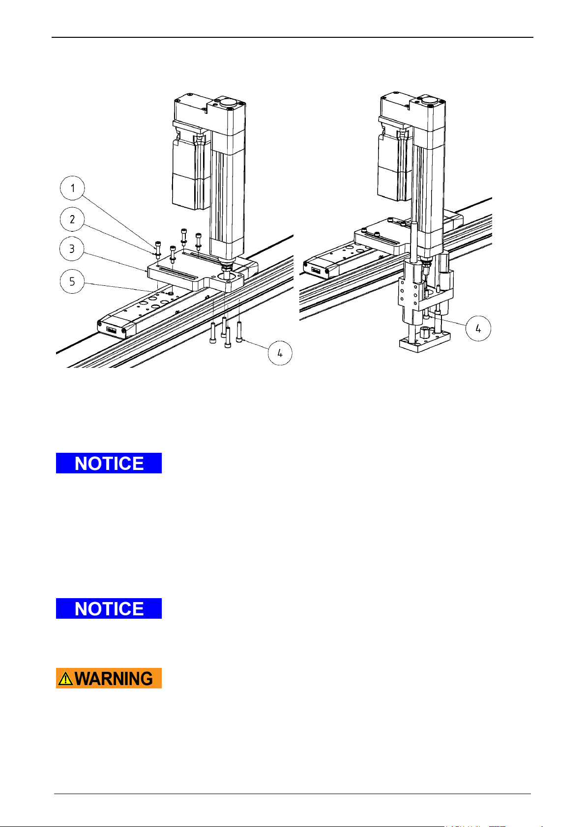
Figure 6: Mounting ETH/ETT032 via bracket plate
The HLR linear axis must be mounted in the system according to these mounting
instructions (see chapter mounting of an individual axis (see page 21)).
Remove both centering sleeves on the carriage of the linear actuator (please
refer to Figure 6: Pos. 5).
Carriage and bracket plate must be clean and free of grease.
Position the bracket plate so that the longitudinal grooves of the bracket plate are
above the mounting threads in the carriage. Depending on the size of the linear
axis, either the outer or inner longitudinal grooves should be used.
Fix the bracket plate with the screws supplied (see Figure 6: Pos. 1) on the
carriage. Position screws only slightly.
Adjust the desired excess of the bracket plate to the linear axis and crosswise
tighten the screws (see Figure 6: Pos. 1) to the respective tightening torque (see
Table 6).
present If this is not the case, mount the motor/gear package according to the
ETH assembly instructions.
When using the ETH cylinder with parallel guide, first remove the parallel guide
Place the ETH/ETT cylinder on the cantilever plate in the centering bore
provided.
Fix the ETH/ETT cylinder crosswise with the screws supplied (see Figure 6: Pos.
4)and the required tightening torque (see Table 6).
When using the ETH cylinder with parallel guide, first place the parallel guide at
the bottom of the outrigger plate and fix the entire unit with the screws supplied.
Page 30

Mounting
HLR Mounting Instruction
30 192-510201N1 HLR 2019-04
Depending on the position of the bracket plate and the load connection, it may not
axis.
HLR070 / HLR080
Screw type [ISO 47621]
+
M5x25 – A2-70
Tightening torque
[Nm]
5.0
Tightening torque ETH/ETT (please refer to Figure 6: Pos. 4)
Screw type [ISO 47621]
-
M6 – A2-70
be possible to use the full stroke of the Z-axis. Consider the height of the HLR
Tightening torque bracket plate (please refer to Figure 6: Pos. 1)
Tightening torque [Nm] 7.5
Table 6: Tightening torques of bracket plate
Page 31
Parker EME
192-510201N1 HLR 2019-04 31
Assembly of Z-axes
3.6.2. Mounting ETH/ETT032 & ETH/ETT050 on double axis via cross beam
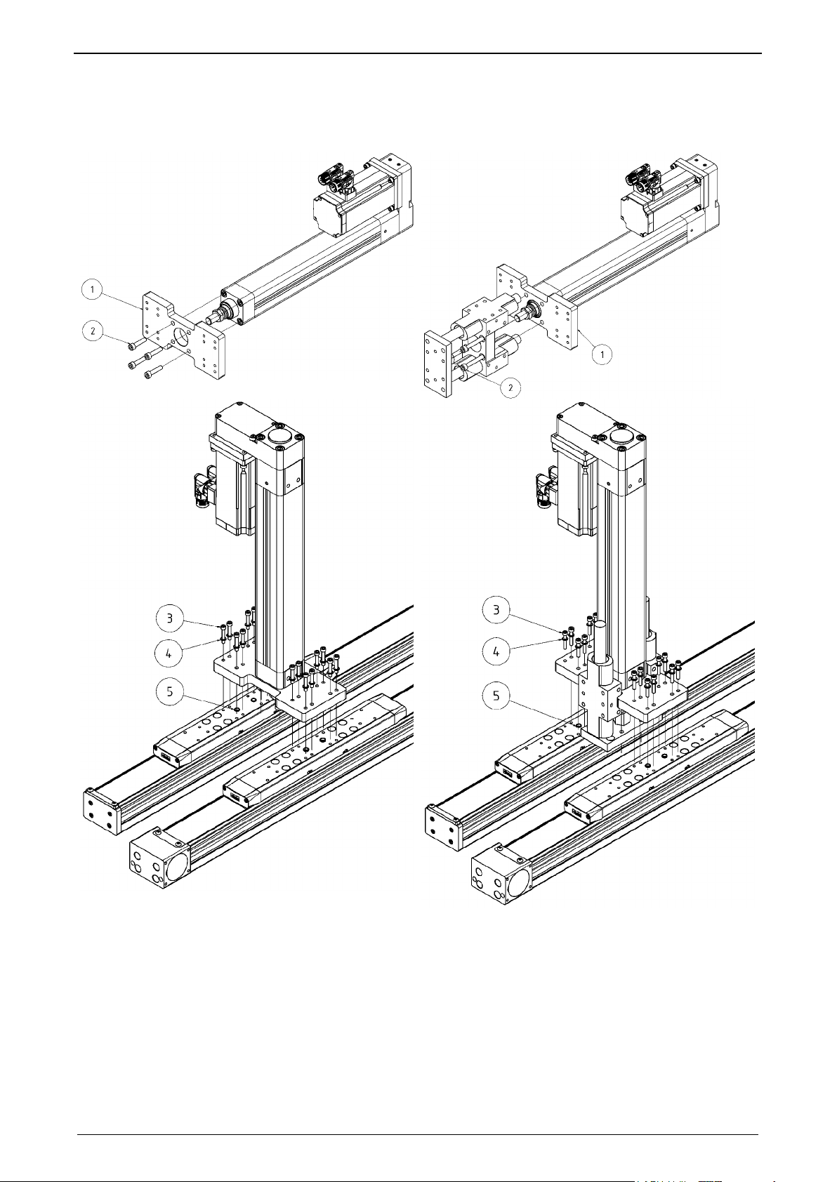
Figure 7: Assembly of ETH032 / 050 to cross beam
The double axes are to be aligned and fastened parallel to each other according
to the assembly instructions (see chapter mounting a double axis (see page 22)).
Make sure the required axis distance for the cross beam is maintained over the
entire length of the axis. Axis distance please refer to the HLR catalogue.
Remove centering sleeves on the carriage of the linear actuator (please refer to
Figure 7: Pos. 5).
Page 32

Mounting
HLR Mounting Instruction
32 192-510201N1 HLR 2019-04
Carriage and bracket plate must be clean and free of grease.
from the cylinder.
Secure the Z-axis + motor/gear against tilting or lowering during the assembly
process.
HLR070
HLR080
Tightening torque ETH/ETT032 (Figure 7, Pos.2)
Screw type [ISO 4762]
-
M6 – A-70
Tightening torque
7.5
Tightening torque ETH/ETT050 (Figure 7, Pos.2)
Screw type [ISO 4762]
M8 – A2-70
Tightening torque
16.0
Tightening torque of cross beam (Figure 7, Pos.3)
Screw type [ISO 4762]
M5x25 – A2-70
M5x35 – A2-70
Tightening torque
[Nm]
5.0
5.0
For the following steps the ETH cylinder with attached motor/gear must be
present If this is not the case, mount the motor/gear package according to the
ETH assembly instructions.
When using the ETH cylinder with parallel guide, first remove the parallel guide
Slide the cross beam (see Figure 7: Pos. 1) onto the centering collar of the
ETH/ETT cylinder.
Fix the ETH/ETT cylinder crosswise with the screws supplied (see Figure 7: Pos.
2)and the required tightening torque (see Table 7).
When using the ETH cylinder with parallel guide, first place the parallel guide at
the bottom of the outrigger plate and fix the entire unit with the screws supplied.
Position the carriages of the double axis side by side and place the
pre-assembled unit (ETH/ETT cylinder with mounted cross beam) on the
carriages of the double axis.
Align the crosswise to the carriage of the double axis and fasten it with the
screws supplied (see Figure 7: Pos. 3) and the required tightening torque (see
Table 7). All bores of the cross beam must be used for bolting to the carriage
profile.
[Nm]
-
[Nm]
-
Table 7: tightening torque of cross beam
Page 33
Parker EME
192-510201N1 HLR 2019-04 33
For the following steps the OSP-E20BV with attached motor/gear must be
OSP-E20BV assembly instructions.
Secure the Z-axis + motor/gear against tilting or lowering during the assembly
process.
Assembly of Z-axes
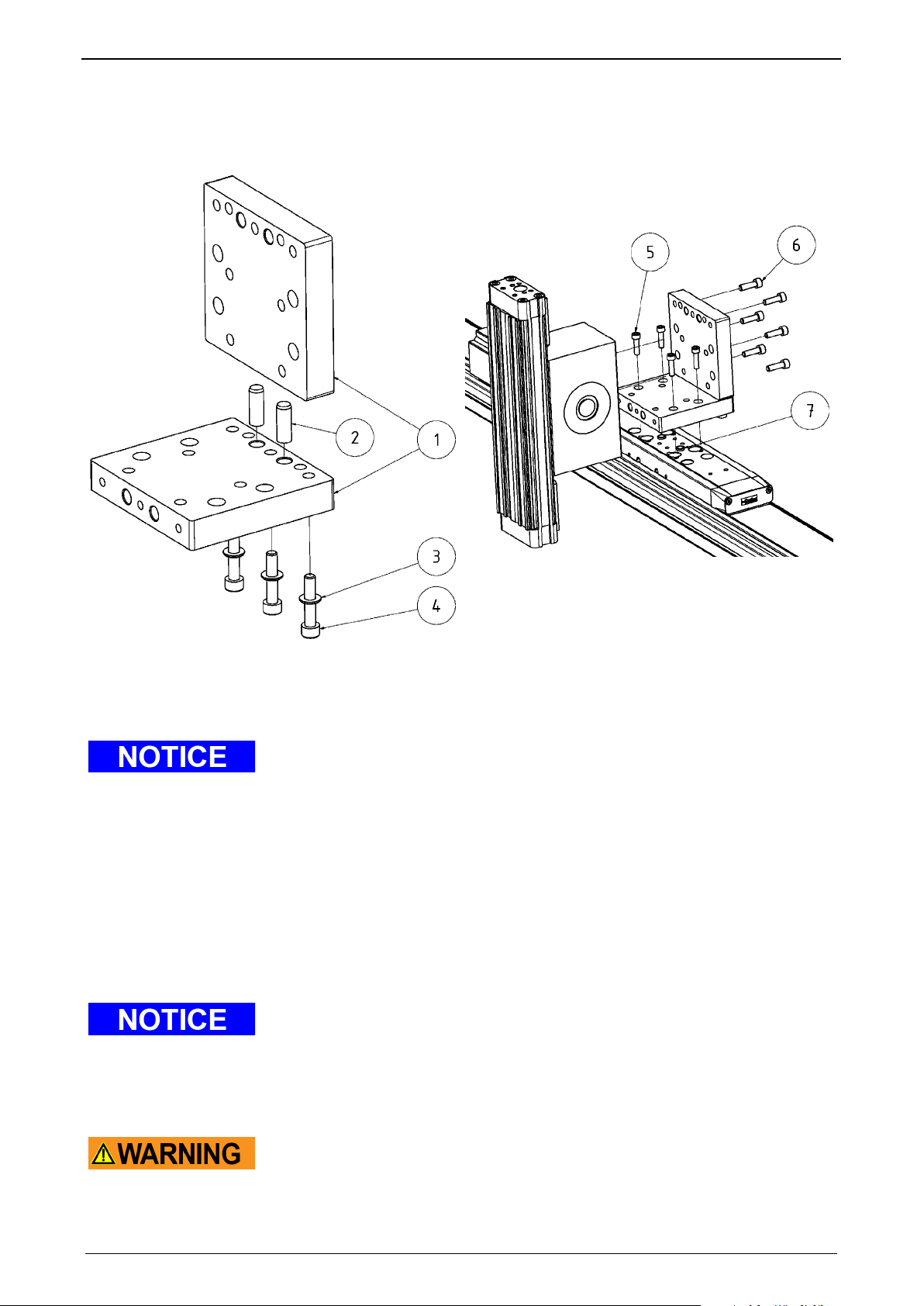
3.6.3. Assembly of OSP-E20BV to single axis via mounting plates
Mounting plates for connecting the OSP-E20BV are only approved for attachment to size HLR080.
Figure 8: Assembly of mounting plates
The HLR linear axis must be mounted in the system according to these mounting
instructions (see chapter mounting of an individual axis (see page 21)).
Remove both centering sleeves on the carriage of the linear axis (please refer to
Figure 8: Pos. 7)
present. If this is not the case, mount the motor/gear package according to the
Pre-assembly of mounting bracket
Press the cylinder pins (see Figure 8: Pos. 2) supplied into the lower mounting
plate (see Figure 8: Pos. 1). Use a one-hand lever press or a comparable,
suitable press-in device.
Then place the upper mounting plate (see Figure 8: Pos. 1) vertically on the lower
mounting plate and press it onto the pre-assembled dowel pins.
Screw together the two mounting plates with the screws supplied (see Figure
8Pos. 4) and the required tightening torque (see Table 8).
Carriage and bracket plate must be clean and free of grease.
Position the pre-assembled mounting plates on the carriage of the HLR linear
actuator, align them parallel to the carriage profile and fix them with the screws
supplied (see Figure 8: Pos. 5) and the required tightening torque (see Table 8).
Page 34

Mounting
HLR Mounting Instruction
34 192-510201N1 HLR 2019-04
HLR080
Tightening torque of mounting plates (Figure 8, Pos.4)
Screw type [ISO 4762]
-
M6x30 – A2-70
Tightening torque
[Nm]
8.8
Tightening torque of mounting plates (Figure 8, Pos.5)
Screw type [ISO 4762]
-
M5x20 – A2-70
Tightening torque
[Nm]
5.0
Tightening torque OSP-E20BV (Figure 8, Pos.6)
Screw type [ISO 4762]
-
M6x20 – A2-70
Tightening torque
[Nm]
6.4
External end stops ........................................................................................................... 36
The position of the permanent magnet is not visible from the outside. Connect the
to determine on which side of the carriage the permanent magnet is located.
Place the OSP-E20BV z-axis on the mounting plate and fasten it with the
supplied screws (see Figure 8: Pos. 6) and the required tightening torque (please
refer to Table 8).
Table 8: Tightening torques of mounting plates for OSAP 20-7
3.7 Assembly of accessories
In this chapter you can read about:
Sensors ........................................................................................................................... 34
3.7.1. Sensors
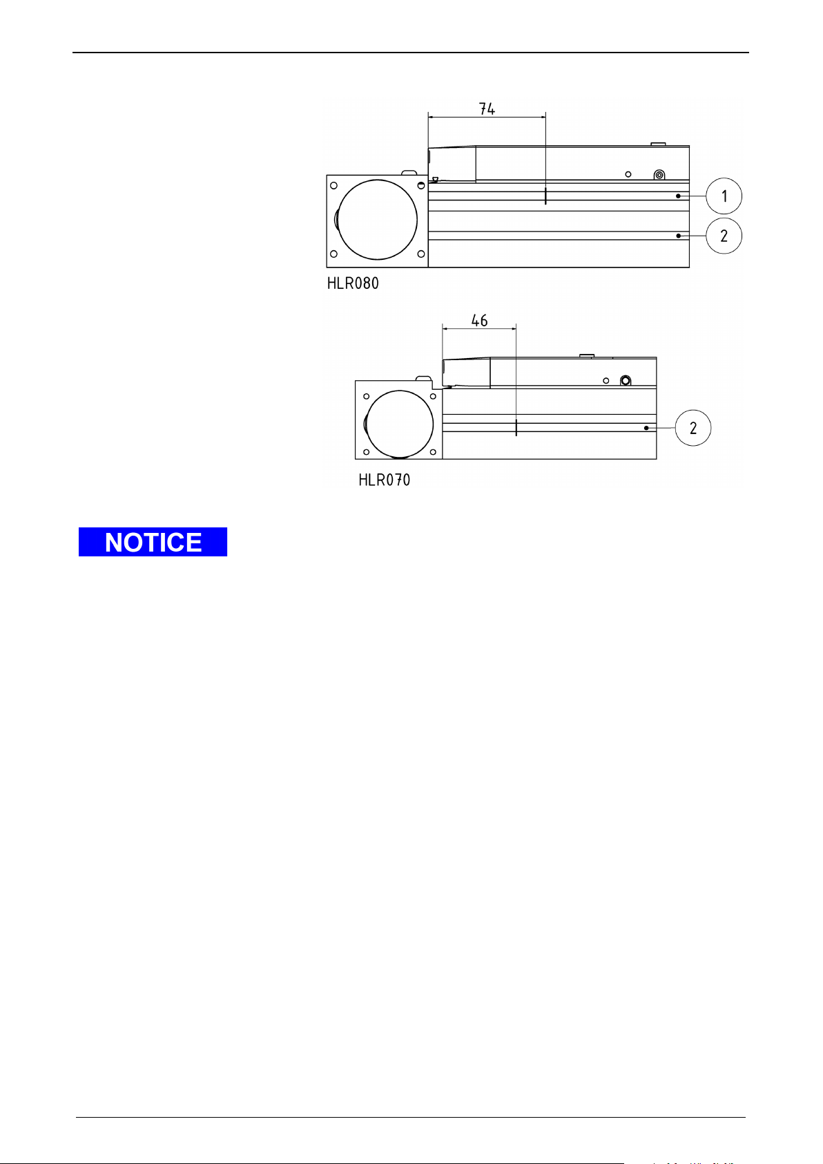
All HLR linear actuators have a permanent magnet integrated in the carriage on
both sides of the support profile. It activates the sensors which are mounted in the
special mounting grooves on the support profile of the cylinder. For sensor
recommended please refer to the HLR catalogue.
Please observe the Operating Instructions of the manufacturer when
commissioning the sensors.
Sensor mounting
Remove the groove cover strips (Figure 9, Pos. 1) from the sensor groove (only
for HLR080) of the support profile.
Insert the sensor into the sensor groove for HLR080 (Figure 9, Pos. 1) and into
the T-slot (Figure 9), Pos.2) for HLR070 and push the sensor to the desired
position (position of the permanent magnet in the carriage profile (see Figure 9).
sensor on the power supply according to the operating instructions and move it in
the support profile along the carriage until the sensor is damped. This allows you
Tighten the fixing screws on the limit switches slightly and lead the cable along
the profile groove.
You can use the formerly removed protective covers (for HLR080 only) in order to
fix the sensor cables. Please cut the covers to the desired length. A pair of
scissors may be used. Insert the cover strips over the sensor cable in the groove
again. Insert the cables into the grooves of the plastic covers and push the cover
into the groove together with the cable.
Connect the sensors to the controller according to the description in the supplier’s
manual.
Page 35
Parker EME
192-510201N1 HLR 2019-04 35
Assembly of accessories
Figure 9: Position of permanent magnets in the support profile
HLR070: Sensor and toe clamps cannot be mounted at the same position at the
support profile.
Page 36
Mounting
HLR Mounting Instruction
36 192-510201N1 HLR 2019-04
External end stops are no safety devices. They are not designed to safely
braked, the linear axis and adjacent machine parts can be irreparably damaged.
HLR070 / HLR080
Tightening torque Toe Clamp Assembly (Figure 10, Pos. 5)
Screw type [ISO 4762]
-
M5x10 – A2-708
Tightening torque*
[Nm]
5.2
After mounting or realigning the external end stops, always carry out a reference
existing travel path.
3.7.2. External end stops
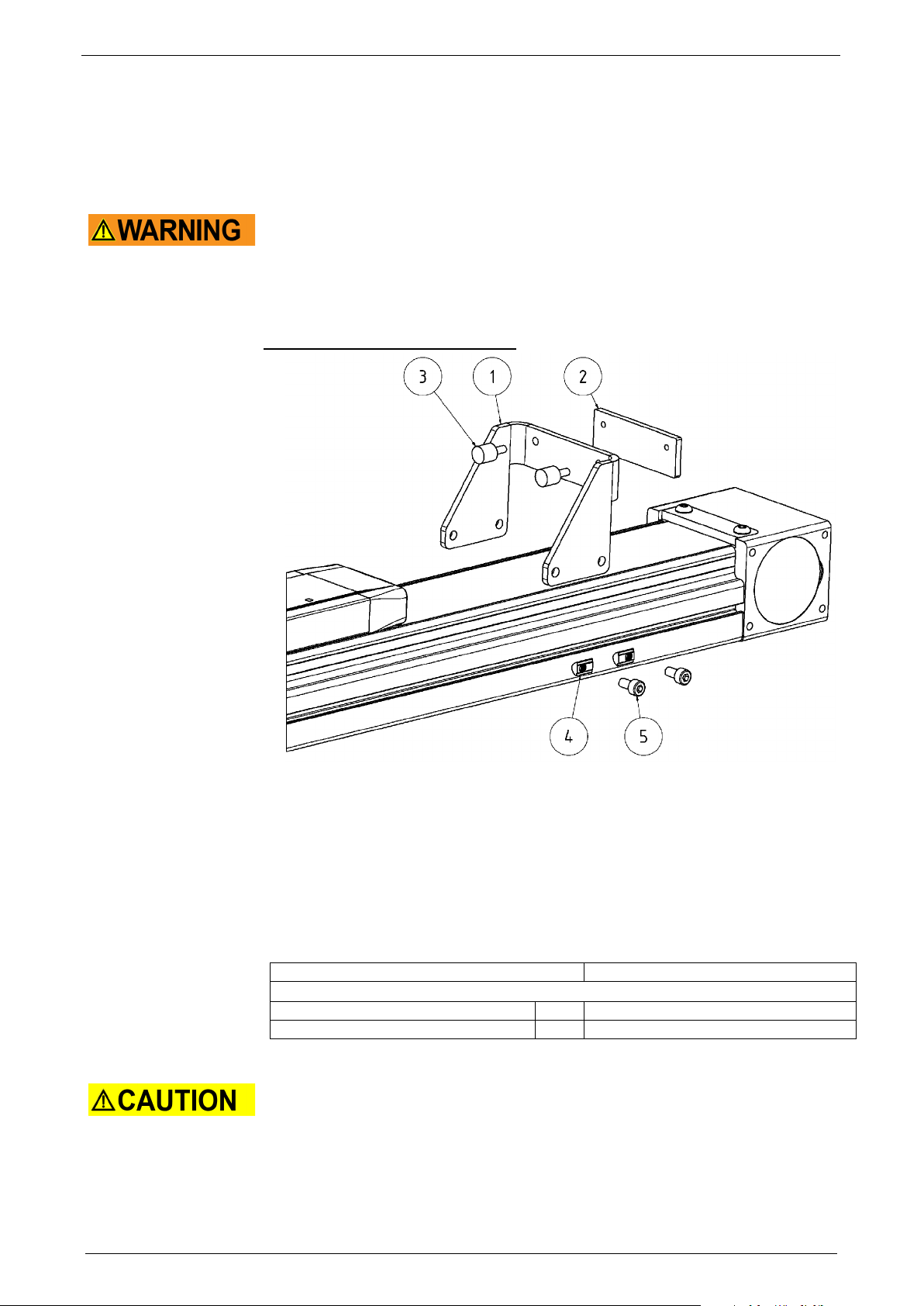
The external end stops can be positioned variably along the support profile and are
suitable for limiting the stroke of the HLR linear axis to protect adjacent machine
parts.
decelerate the maximum possible impact energy of the HLR linear axis. If the
impact against the external or internal end stops of the HLR linear axis is not
Dimensions of the external stops please refer to dimensions (see page 17).
Assembly of the external end stop
Place the thread plate (Figure 10, Pos. 2) on the external end stop (Figure 10,
Figure 10: External end stop
Pos. 1) and screw it to the buffers (Figure 10, Pos. 3).
Insert the slot nuts (Figure 10, Pos. 4) into the clamping profiles of the HLR
linear axis, two in each groove and roughly position them for the external stop.
Slide the external stop onto the support profile (with the buffers in the direction of
the carriage), over the slot nuts and screw-in the screws supplied (Figure 10,
Pos. 5) (do not fastenn).
Move the external stop to the desired position and tighten the screws (Figure 10,
Pos. 5) with the required torque (see Table 9).
Table 9: Tightening torques of the external end stop
run (setting the end limits) and set the software end limits according to the
Page 37

Parker EME
192-510201N1 HLR 2019-04 37
Use at elevated ambient / operating temperatures ........................................................... 38
During commissioning, special care must be taken to ensure that no objects or
gear) as well as the control system.
Vibrations, oscillations or unusual running noises indicate poorly adjusted control
running behaviour and the expected service life of the linear axis.
4. Commissioning
In this chapter you can read about:
General notes on commissioning ..................................................................................... 37
4.1 General notes on commissioning
persons are within the operating range of the linear actuator (or the system).
Always carry out commissioning at reduced speed. Do not reach to the action
arear of the linear actuator during commissioning.
The commissioning of the HLR Linear actuator may only be carried out by
qualified personnel. This person is sufficiently informed about the safety
instructions in this manual and how to handle the drive components used (motor,
The below described notes for commissioning of the HLR Linear actuator are very
general. Depending on the operating conditions, appropriate measures must be
taken to ensure safe and correct commissioning of the linear axis (or the system).
General notes on commissioning
Commissioning
Before commissioning, make sure that the operating range of the linear axis (or
system) is free.
At the beginning of commissioning, check that the reference system of the
control system corresponds to your system. To do this, move the carriage in one
direction by a defined distance. If the carriage does not move in the desired
direction, the motor direction of rotation is incorrectly set. If the carriage does not
move by the specified distance, the parameters travel per motor revolution (see
page 16) or "gear ratio" are set incorrectly.
Set the software end limits so that they lie within the hardware end limits and
provide sufficient safety travel. Move the carriage at reduced speed over the
entire stroke to ensure that the software end limits are set correctly and that the
hardware end limits are not approached.
If it is necessary to approach the hardware end limits, do so only at reduced
speed (≤10 mm/s) and reduced motor current.
Optimize the motor control to the desired behaviour of the Linear actuator (or the
system).
or mechanical distortion of the linear axis. These have a negative influence on the
Limit the parameters speed, following error and motor current to what is required
for normal operation (approx. 10 to 20% more). This minimizes the probability of
an overload of the entire drive train in the event of a fault, and a possible negative
change in the running behavior is detected at an early stage.
Page 38

Commissioning
HLR Mounting Instruction
38 192-510201N1 HLR 2019-04
4.2 Use at elevated ambient / operating temperatures
The operation of the HLR linear actuator at high ambient and/or operating
temperatures leads to a heating of the complete linear axis. Due to the different
expansion coefficients of the support profile and the steel strip cover, these expand
differently. With increasing ambient and/or operating temperature, the expansion
difference increases steadily. The support profile expands more than the steel strip
cover. This leads to a tightening of the steel strip cover and increases the friction
on the wear parts, which further increases the operating temperature of the linear
actuator.
Uncontrolled heating of the linear axis can lead to increased wear on the steel
strip cover and irreparable damage to the linear actuator.
Factors influencing the heating of the linear actuator
Ambient temperature - this is the temperature of the air surrounding the linear
actuator. It is influenced by the environment of the linear actuator e.g. heating by
neighbouring devices, plant components or processes.
Opearating temperature - is the temperature of the linear actuator which is
converted into heat by the resulting power loss. The power dissipation is primarily
influenced by the operating data duty cycle and feed rate.
If one of the operating data listed below is exceeded, the tension of the steel strip
cover must be checked and corrected if necessary.
Ambient temperature >30 °C or
Duty cycle >50 % and feed rate >2 m/s
Correct tension of the steel strip cover
The HLR Linear actuator is installed and commissioned according to the manual.
Start normal operation of the linear axis (the entire system) and warm up the
linear axis.
Check the tension of the steel strip every 60 minutes (with duty cycle 80...100 %
every 30 minutes).
Stop the linear axis (the entire system) and switch off the power to the required
drives.
Loosen one of the steel strip cover terminal strips (see Figure 13, Pos. 1) Do not
entirely screw-off screws
Steel strip cover releases automatically (see Figure 13, Pos. 5) as soon as the
terminal strip was losened.
Tip: A fine marking on the steel strip and profile visualizes the adjustment of the
steel strip cover.
Retighten the screws of the steel strip cover terminal strips (see Figure 13, Pos.
2) with the tightening torque (see page 43) indicated and resume operation of the
linear axis (of the entire system).
Repeat the process described above until the linear axis has reached its final
operating temperature and no adjustment of the steel strip cover is visible.
Page 39

Parker EME
192-510201N1 HLR 2019-04 39
Spare and Wear Parts ..................................................................................................... 50
Before carrying out any installation work make sure that the carriage cannot
again.
The linear actuator guidance system is susceptible to dirt and foreign particles.
the guidance system and may deposit there.
5. Maintenance and service
In this chapter you can read about:
General maintenance notes ............................................................................................. 39
Maintenance schedule and replacement intervals ............................................................ 40
Lubrication of the guiding system ..................................................................................... 41
Steel strip cover disassembly and replacement ............................................................... 43
Toothed belt .................................................................................................................... 45
Replace carriage lid ......................................................................................................... 49
Check steel strip deflectors and steel strip sliding rods .................................................... 50
Exchange guiding system ................................................................................................ 50
General maintenance notes
5.1 General maintenance notes
move. Therefore, de-energize the respective drive or the complete system In
vertical applications, the carriages of the linear axes are secured against
displacement. Secure the drives or the entire system against being switched on
Please observe the general safety instructions (see page 8) and chapter specific
safety instructions.
During maintenance work please take care that no dirt or foreign particles enter
Page 40

Maintenance and service HLR Mounting Instruction
40 192-510201N1 HLR 2019-04
When
What
Action / elimination
Chapter
Visually inspect linear actuator for damages and
contact Parker.
At downtimes ≥ 1 year: Relubricate (Manufacturing
date- please refer to the type plate).
Visually inspect and clean carriage, lip seal, cover
Clean daily when heavily soiled.
Description (see
page 41)
Lip seal of carriage
lid
Visual inspection for dirt and wear. Celan when
heavily soiled. Replace if worn.
Check pre-tension and wear. Visually assess the
the toothed belt.
What
Mileage
Action
Elimination
Description (see
page 49)
Steel strip sliding rods
15,000
to be replaced
Steel strip cover
Ball bearing
5.2 Maintenance schedule and replacement intervals
Maintenance schedule
For
commissioning
1 x half-yearly
Once a year when
reaching lubricating
intervals
Linear actuator
free movement of carriage. In case of stiffness,
Guiding unit
strip, deflection station, connection shaft and drive
Linear actuator
unit.
Lightly wet the steel strip over its entire length with
PTFE spray (Teflon spray).
Guiding unit Relubricate
Visual inspection for damage and wear. Clean
Steel strip cover
when soild and lightly wet over its entire length with
PTFE spray (Teflon spray). Clean daily when
heavily soiled.
Replace if damaged or worn.
Toothed belt
wear of the toothed belt. If it is too high, exchange
Description (see
page 41)
Description (see
page 49)
Description (see
page 43)
Description (see
page 45)
Table 10: Maintenance plan
Replacement interval:
Lip seal
Steel strip deflection
Toothed belt
Guiding unit
Table 11: Replacement intervals
15.000 to be replaced
15,000 to be replaced
According to life cycle
of the lLinear actuator
*
Replace linear
actuator
Description (see
page 50)
* Life cycle of guiding systems depends on application, see calculation HLR
Catalogue.
Page 41
Parker EME
192-510201N1 HLR 2019-04 41
Before working with lubricants please read the respective supplier manuals and
adhere to it.
Improper or insufficient lubrication or wrong lubricant can cause irreparable
expected lifetime may reduce significantly.
Linear actuators are lubricated before shipment. In the case of storage or
reached.
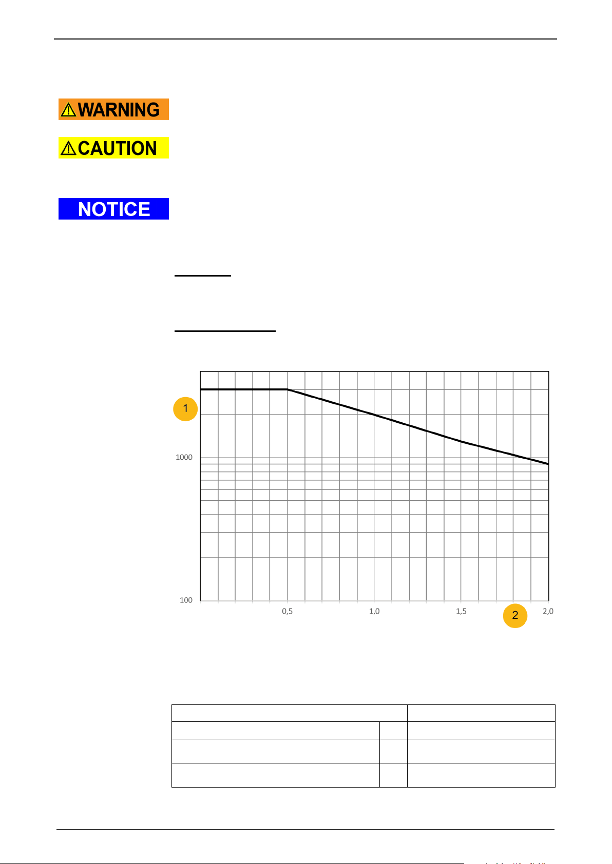
1
Lubrication interval [km]
2
Load comparison factor fv*
* Calculation of the load comparison factor please refer to the HLR catalogue.
Lubricating amount depending on
lubricating nozzle
Lubricating amount per carriage / Linear
actuator
5.3 Lubrication of the guiding system
Lubrication of the guiding system
damage to the linear actuator guidance system and result in e.g. higher wear,
reduced precision, higher friction and higher noise level.
Furthermore, the
downtimes of more than 1 year, the guiding system of the linear axis must be
lubricated before initial operation. For low mileages, the linear axis guide must be
lubricated at least once a year, even if the lubrication interval has not been
Grease gun
To relubricate the guiding system, use a grease gun suitable for the grease
nipples. We recommend a one-hand lubrication press (optionally available, article
number see HLR catalogue) with nozzle attachment type D1a4 (DIN3405).
Lubrication intervals
Minimum lubrication intervals for grease are influenced by different parameters
(time, load ratios, operating loads). Minimum lubrication intervals can be seen in
the following diagram.
Figure 11: Lubrication intervals of the guiding system
Lubricant and amount of lubricant
HLR070 / HLR080
[g]
[g]
-
Klüberplex BEM34-132
1.2
2.4
Recommended lubricant
Table 12: Lubricant and amount of lubricant
Page 42
Maintenance and service HLR Mounting Instruction
42 192-510201N1 HLR 2019-04
Procedure
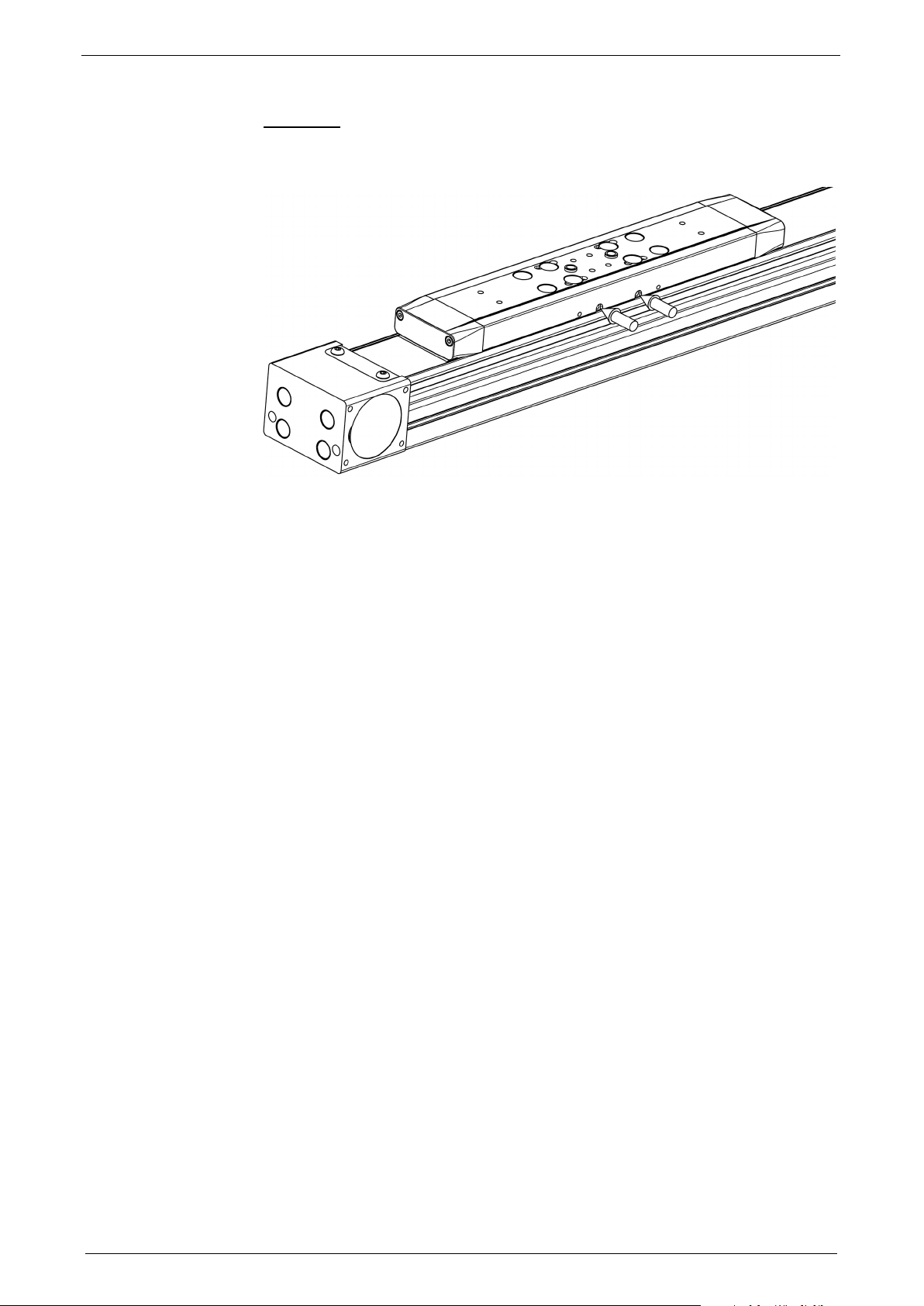
Standard carriages of HLE linear actuators have two greasing nozzles per carriage
side. Both lubricating nozzles are to be filled with the respective lubricant amount
on one side of the carriage.
Figure 12: Lubrication of the guiding system
Position the carriage at any point.
Repeat the following process twice
Fill each grease nozzle (only on one side of the carriage) with the required
amount of lubricant by slowly actuating the grease gun ½ (see Table 12). When
using the recommended lubricant and the recommended grease gun, half the
lubricant quantity corresponds to two full pump strokes.
Move the carriage at least twice the rotor length in one direction. For strokes
smaller than the carriage length, move the carriage twice, forwards and
backwards over the entire stroke.
Page 43
Parker EME
192-510201N1 HLR 2019-04 43
Steel strip cover is sharp-edged. If handled carelessly during maintenance, you
might cut yourself. Protection gloves must be worn!
After dismantelling the carriage lid, the frontal stop surface of the carriage is
Protection gloves must be worn!
Take care when loosening or screwing in the round-head screws. Make sure that
specified tightening torque.
Steel strip cover disassembly and replacement
5.4 Steel strip cover disassembly and replacement
sharp-edged. If handled carelessly during maintenance, you might cut yourself.
The steel strip cover used does not have to be changed over the entire service life
of the linear axis, taking into account the technical axis data and boundary
conditions. However, due to external influences or misuse, the steel strip cover
may be damaged (scratches, dents or cracks) in these cases the cover must be
replaced.
Dismantling and assembly procedure
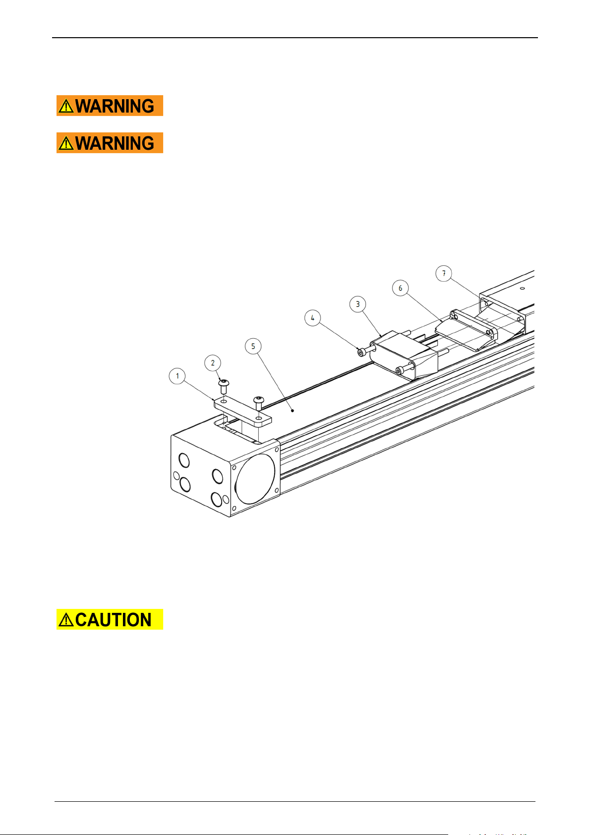
Figure 13: Disassembly of steel strip cover
Deflection station and carriage lid must be accessible for the following steps.
Dismantle parts and loads if necessary.
Position the carriage in the middle of the profile.
Loosen screws (Figure 13, Pos. 2) of the steel strip cover terminal strips on both
deflection stations (Figure 13, Pos. 1) and remove terminal strip.
the tool is axial to the screw and engages completely in the hexagon socket to
prevent damage to the screw head.
When tightening the screws, observe the
Loosen screws of both carriage lids (Figure 13, Pos. 4) land remove carriage lid
(Figure 13, Pos. 3).
Carefully pull out steel strip cover (Figure 13, Pos. 5).
Carefully pull out steel strip deflections (Figure 13, Pos. 6) and steel strip sliding
rods (Figure 13, Pos. 7).
Check support profile and carriage for dirt, foreign bodies or damage. Carefully
remove heavy dirt and foreign objects.
Page 44

Maintenance and service HLR Mounting Instruction
44 192-510201N1 HLR 2019-04
When replacing the steel strip cover, it is recommended to visually check and
(Details (see page 49)).
Take care that the carriage lid is aligned exactly to the carriage profile (lip seal
risk of premature wear.
Ensure that the steel strip cover lies centrally in the profile over its entire length.
deflections and the steel strip cover.
HLR070 / HLR080
Tightening torque of the carriage lid (Figure 13, Pos. 4)
Screw type [ISO 4762]
-
M4x60 – A2-70
Tightening torque
[Nm]
1.6
Screw type [ISO 7380]
-
M5x10 – A2-70
Tightening torque
[Nm]
2.4
clean the wearing parts of the lip seals in the carriage lids, steel strip deflections
and steel strip sliding rods and to replace them depending on their condition
For the installation of a new steel strip cover, cut the new steel strip cover to the
required length using suitable sheet metal shears. Use the old steel strip cover as
matrix.
To install the old steel strip cover, clean both sides of the old steel strip cover
before reinstalling it.
Carefully slide the steel strip cover through the carriage and place it on the
support profile.
Thread the steel strip deflectors (Figure 13, Pos. 6) left and right onto the steel
strip cover. When installing the old steel strip deflectors, clean them before
reinstalling them.
Push the steel strip deflectors as far as the carriage and carefully push them back
into the carriage, up to the stop.
Carefully push the steel strip sliding rods (Figure 13, Pos. 7) through the
carriage profile and the steel strip covers. Make sure that the steel strip sliding
rods are seated in the profile over the entire length of the carriage and do not
hang out downwards.
Fit the carriage lid (Figure 13, Pos. 3) on both sides and tighten the screws
(Figure 13, Pos. 4) to the required tightening torque (see Table 13). Clean the lip
seal before assembling the old lid.
parallel to the steel strip cover). If the lip seal is mounted at an angle, there is a
Align the steel strip cover over the entire profile length.
In the off-centre position there is a risk of premature wear of the steel strip
Clamp the steel strip cover (Figure 13, Pos. 5) with steel strip cover terminal strip
(Figure 13, Pos. 1) on one of the two deflection station. Tighten screws with the
respectable tightening torque (see Table 13).
Move carriage to the deflection station with the assembled terminal strip.
Smooth the steel strip cover (Figure 13, Pos. 5) in the direction of the second
deflection station by hand and clamp it to the deflection station using the steel
strip cover terminal strip. Tighten screws to the respectable tightening torque (see
Table 13).
Check if the steel strip cover is touching the carriage. Therefore move the
carriage over the entire length of the stroke and pay attention to grinding noises.
In the stroke area slightly moisten the steel strip with Teflon spray.
Tightening torque Steel Strip Option (Figure 13, Pos. 2)
Table 13: Tightening torques of steel strip cover
Page 45
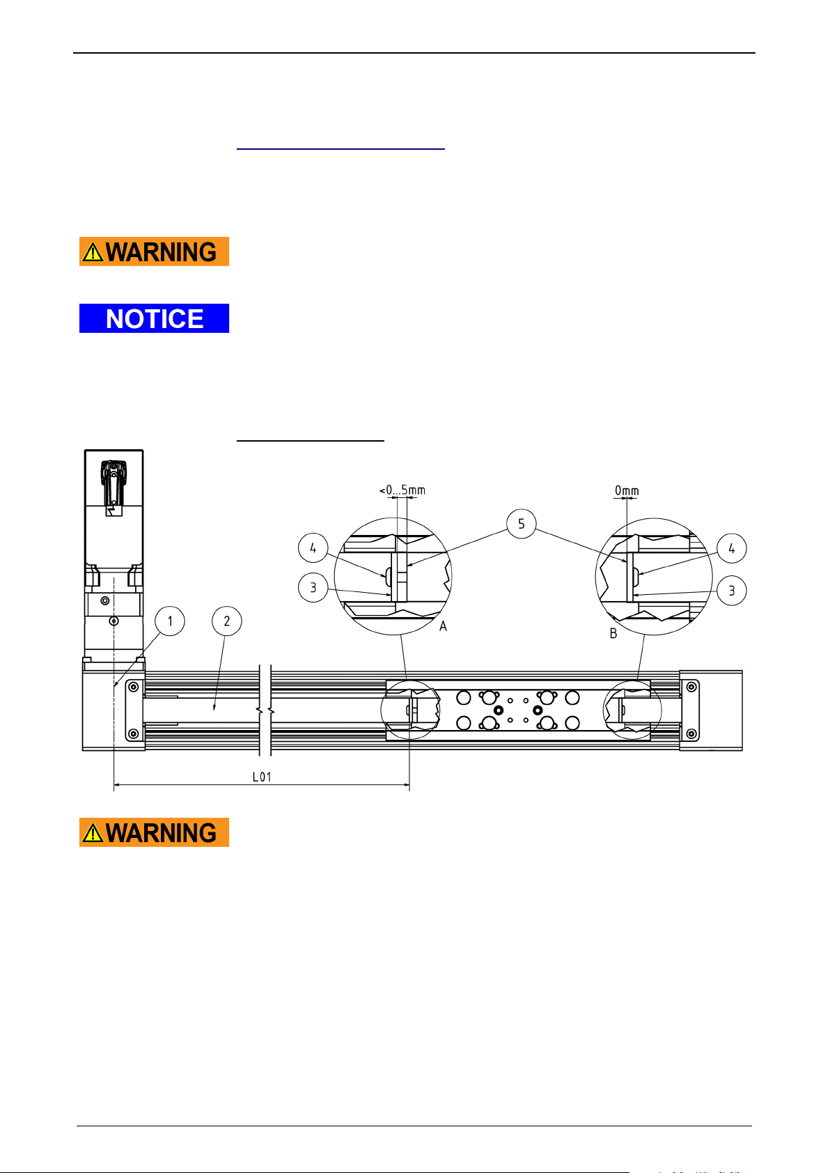
Parker EME
192-510201N1 HLR 2019-04 45
Exchanging the toothed belt ............................................................................................ 47
An uncorrect toothed belt tension may cause the belt to jump. This may cause a
personal injuries. Belt pre-tension must always be observed.
Toothed belt pre-tension is matched to the technical axis data and considers
toothed belt is not necessary.
After dismantelling the carriage lid, the frontal stop surface of the carriage is
Protection gloves must be worn!
5.5 Toothed belt
In this chapter you can read about:
Checking and setting toothed belt tension........................................................................ 45
5.5.1. Checking and setting toothed belt tension
loss of position. This may lead to collisions or may cause property damage and
possible belt tension losses after installation. When operating under normal
conditions and in compliance with technical specification, re-tensioning of the
Is a belt tension loss suspected, the toothed belt tensions must be verified and if
necessary corrected as follows:
Assembling sequence
Toothed belt
Figure 14: Check and adjust toothed belt tension
sharp-edged. If handled carelessly during maintenance, you might cut yourself.
Dismantle and put aside steel strip cover, steel strip deflectors and steel strip
sliding rods (see page 43).
If possible, carefully drive carriage to end stop of pulley housing.
Check belt on both carriage sides for abnormal wear (belt back and tooth flanks).
In case of heavy wear, we recommend replacing the toothed belt (see page 47).
Measure the free belt length (Figure 14, L01) between the middle level of the
pulley (Figure 14, Pos. 1) and the belt tensioning element (Figure 14, Pos 3).
Enter the measure belt length (Figure 14, L01) as well as the belt weight (Table
14) in the belt tension gauge.
We recommend to use the gauges “Sonic 507c” of the company Gates resp. the
"Trummeter" gauge of the company Hilger&Kern. For precise measurement, the
operating manual of the measurement equipment must be observed.
Page 46

Maintenance and service HLR Mounting Instruction
46 192-510201N1 HLR 2019-04
Take care when loosening or screwing in the round-head screws. Make sure that
prevent damage to the screw head.
One of the clamping screws is turned to the stop at the factory (Figure 14, detail
mm on both sides, otherwise the steel belt deflections cannot be fitted.
When moving the carriage during tensioning, make sure that the free, measured
on the profile and always move it to this position for the measurement.
[g/m]
[N]
[N]
[N]
HLR070
80
550
605 ± 30
690 ± 30
HLR080
117.5
990
1090 ± 50
1240 ± 50
Please check toothed belt tension in the center of the free belt length. If the
toothed belt tension is below the permissible operating tension, the toothed belt
must be tensioned to the "standard belt tension when retensioning". (please refer
to Table 14). Toothed belt tension may not exceed "Standard belt pre-tension of
new belts”. In this case the toothed belt tension must be reduced.
Depending on toothed belt tensions, carefully screw-in resp. screw-out the
tension screw in the carriage (Figure 14, Pos 4).
the tool is axial to the screw and engages completely in the hexagon socket to
view B). This is indicated by the fact that this clamping screw is screwed in
deeper and cannot be screwed in any further. To increase the toothed belt
tension, the other tensioning screw (
Figure 14, detail view A) must be screwed in.
To reduce toothed belt tension, both tensioning screws can be released.
The belt tensioning elements (Figure 14
, Pos. 3) must not protrude more than 5
After each adjustment of the clamping screw, move the carriage forwards and
backwards once over approx. the carriage length.
belt length matches the value in the gauge. Tip: Mark the position of the carriage
Then measure the toothed belt tension in the center of the free belt length.
Repeat the three steps described above until the required toothed belt tension is
reached.
If both tensioning screws are screwed in at the stop (as shown in Figure 14, detail
view B) and the required toothed belt tension has not yet been achieved, the
toothed belt (Figure 14, Pos 2) must be shortened by one tooth.
Loosen one of the tension screws completely (see Figure 14, Pos. 4).
Carefully pull the toothed belt with the belt tensioning element (Figure 14, Pos. 3)
out of the carriage (depending on the design, the belt tensioning element is
one-piece or two-piece).
Shorten the toothed belt for one tooth. Cut off the toothed belt exactly in the tooth
base.
Insert again the boothed belt (Figure 14, Pos. 2) with the belt tensioning element
(Figure 14, Pos. 3) into the carriage.
The toothed belt must fit into all teeth of the belt tensioning element.
Screw-in tensioning screw (Figure 14, Pos. 4) until the toothed belt tightens.
Measure the toothed belt tension as described above and adjust the tension
screw accordingly until the required toothed belt tension is achieved.
If the required toothed belt pre-tensions ist set, steel strip cover, steel strip
Belt weight per
meter
deflectors and steel strip sliding rods (see page 43) can be reassembled again.
Operating voltage
Standard belt tension during
retensioning
Standard belt tension of new belt
Table 14: toothed belt characteristics
Page 47
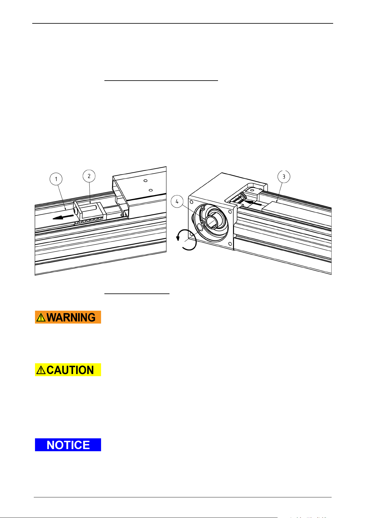
Parker EME
192-510201N1 HLR 2019-04 47
After dismantelling the carriage lid, the frontal stop surface of the carriage is
Protection gloves must be worn!
Take care when loosening or screwing in the round-head screws. Make sure that
prevent damage to the screw head.
5.5.2. Exchanging the toothed belt
Taking into consideration the technical axis data and boundary conditions, the
toothed belt used is maintenance-free and must not be changed.
Causes for abnormal toothed belt wear
Due to external influences or error applications, a toothed belt exchange might be
necessary. Causes for abnormal toothed belt wear are:
toothed belt tension too big or too small
impermissibly high drive torque, braking torque, or feed force
operating or ambient temperature too high
Contact with chemicals
A certain sign of wear may have different causes so that it is not always possible to
determine the exact cause. In case of abnormal belt wear it is recommended to
replace the belt and to check the application for the above mentioned "causes of
abnormal belt wear".
Toothed belt
Figure 15: Toothed belt exchange
Assembling sequence
Dismantle and put aside the drive from the Linear actuator (see page 27).
sharp-edged. If handled carelessly during maintenance, you might cut yourself.
Dismantle and put aside steel strip cover, steel strip deflectors and steel strip
sliding rods (see page 43).
the tool is axial to the screw and engages completely in the hexagon socket to
Loosen screws of the belt tensioning element Figure 15, Pos. 2) on both sides,
carefully pull out and put aside the toothed belt with the belt tensioning element
(Figure 15, Pos. 1) of the carriage (depending on the design, the belt tensioning
element is one-piece or two-piece).
Pull out belt on one axis side.
Clean the interior of the linear axis, deflection stations and carriage profile
(grease, abrasion, other impurities).
Cut the replacement belt to the required length using suitable sheet metal shears.
Use the old steel strip cover as matrix.
Page 48

Maintenance and service HLR Mounting Instruction
48 192-510201N1 HLR 2019-04
Insert the replacement toothed belt (Figure 15, Pos. 3) into the upper opening of
one of the return stations and push the toothed belt around the toothed pulley
(Figure 15, Pos. 4) . In order to facilitate installation, turn pulley in pushing
direction.
Push in the toothed belt further until the toothed belt runs through the profile and
runs around the toothed pulley in the opposite deflection station. In order to
facilitate installation process, turn pulley of the opposite deflection station in
pushing direction.
Pull the toothed belt out of the opposite deflection station and place both ends of
the toothed belt on the carriage.
Insert one toothed belt end into the toothed belt tensioning element (Figure 15,
Pos. 2) and screw it in on one side of the carriage.
The toothed belt must fit into all teeth of the belt tensioning element.
Insert the second toothed belt end into the belt tensioning element, insert it on the
other side of the carriage and adjust the toothed belt tension to the "standard belt
pre-tension of new belts” (see page 45) with the tensioning screw, see Table 14).
After the toothed belt tension has been correctly adjusted, the steel strip sliding
rods, steel strip deflections, steel strip cover, carriage lid (see page 43) and drive
(see page 27) can be reassembled.
Page 49
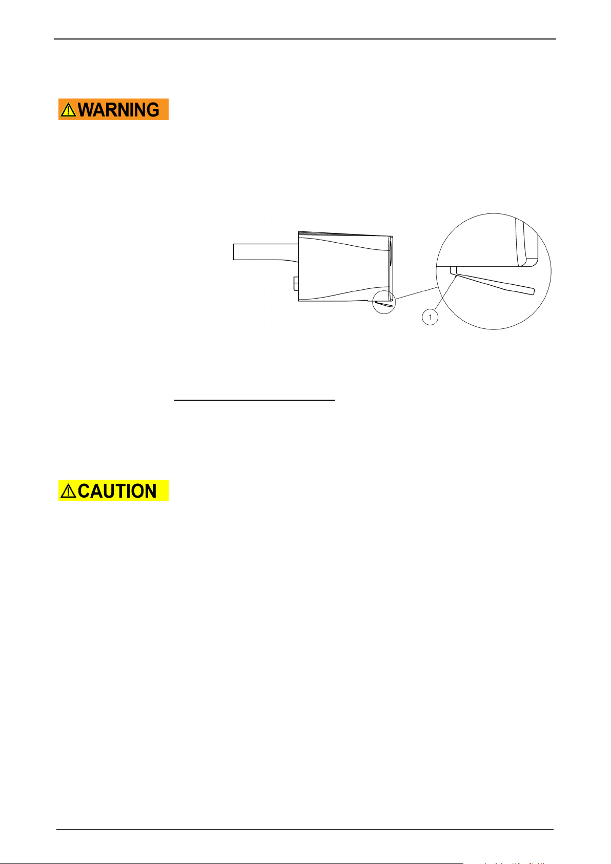
Parker EME
192-510201N1 HLR 2019-04 49
After dismantelling the carriage lid, the frontal stop surface of the carriage is
Protection gloves must be worn!
Take care that the carriage lid is aligned exactly to the carriage profile (lip seal
risk of premature wear.
5.6 Replace carriage lid
sharp-edged. If handled carelessly during maintenance, you might cut yourself.
Carriage lids must be exchanged if:
the recommended exchange interval of the lip seal is reached (see Table 11).
abnormal or one-sided wear is present on the lip seal (Figure 16, Pos 1), due to
improper operation or environmental influences or incorrect installation
(misalignment) of the steel belt cover or carriage cover.
Replace carriage lid
Figure 16: Abnormal wear of lip seal
or after a collision with adjacent machine parts, provided that important functional
parts of the linear axis have not been damaged (guide, carriage, toothed belt,
deflection stations). In this case, the complete axis must be exchanged.
Exchange process of carriage lid
To exchange the carriage lid, it is not necessary to loosen the steel strip cover.
Loosen the screws of the cover lid (see Figure 13, Pos. 4) and dispose the old lid
(see Figure 13, Pos. 3).
Position the new carriage lid on the carriage plate and screw it to the required
tightening torque see Table 13).
parallel to the steel strip cover). If the lip seal is mounted at an angle, there is a
Check if the steel strip cover is touching the carriage. Therefore move the
carriage over the entire length of the stroke and pay attention to grinding noises.
In the stroke area slightly moisten the steel strip with Teflon spray.
Page 50
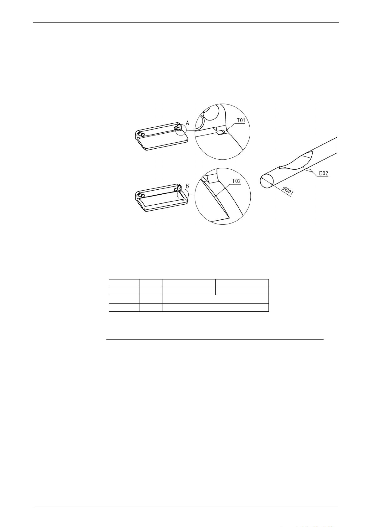
Maintenance and service HLR Mounting Instruction
50 192-510201N1 HLR 2019-04
HLR070
HLR080
T01
1.0
1.5
T02
1.0
D02
[mm]
ØD01 - 0.2
5.7 Check steel strip deflectors and steel strip sliding rods
Steel strip deflections and steel strip sliding rods must be exchanged if:
the recommended exchange interval of the wear parts is reached (see Table 11).
abnormal or one-sided wear is present on the wear parts, due to improper
operation conditions or environmental influences, extensive soiling from outside
or incorrect installation of the steel belt cover.
Figure 17: Abnormal wear of steel strip deflecion (left) and steel strip sliding rods (right)
Abnormal wear is present if
At the steel strip deflection the lateral residual web thickness falls below the value
T01 or the wear at the sliding surface exceeds the value T02.
At the steel strip sliding rod the thickness of the sliding rod falls below the value
D02
[mm]
[mm]
Table 15: Abnormal wear limit values
Exchange procedure of steel strip deflections and steel strip sliding rods
To exchange the carriage lid, it is not necessary to to completely remove the steel
strip cover (see page 43).
5.8 Exchange guiding system
Exchanging the guiding system is only possible at the assembly plant and not at
customer's site.
If damaged (due to impacts, soiling, loads or environmental conditions), the
complete linear axis must be exchanged. Furthermore, it should be exchanged as
soon as the forecasted lifetime of the linear actuator is reached.
Page 51

Parker EME
192-510201N1 HLR 2019-04 51
Spareparts ....................................................................................................................... 51
Part number
HLR070
HLR080
Steel strip deflection*
Part number
HLR070
HLR080
Toothed belt*
Steel strip cover*
Clamp collar incl. clamping
screw
5.9 Spare and Wear Parts
In this chapter you can read about:
Wear parts ....................................................................................................................... 51
Spare and Wear Parts
5.9.1. Wear parts
Order unit
Carriage lid incl. lip seal*
Steel strip sliding rods 350 mm*
Table 16: Wear parts
* Min. Order amount 2 pieces
5.9.2. Spareparts
Order unit
Table 17: Spare parts
* Can only be ordered in full meters
[Piece]
[Piece]
[Piece]
[m]
[m]
[Piece]
0231.023 0241.023
0231.038 0241.038
0231.039-01
0231.904 0241.904
400-300704 400-300711
0232.007-03 0242.007-03
Page 52

Supply repair
HLR Mounting Instruction
52 192-510201N1 HLR 2019-04
6. Supply repair
In the event of a damage or a mechanical defect, the entire unit must be returned
for repair (Parker Hannifin (see page 1)). The repair must be made by trained
Parker personnel.
User conversions and changes are not Permitted
The linear actuator must not be changed in its design or in terms of safety without
our approval. Any change as defined here made by the user excludes any liability
on our part.
Page 53

Parker EME
192-510201N1 HLR 2019-04 53
7. Index
Spare and Wear Parts
A
Alignment of a double axis • 22
Applications in accordance with the
Regulations • 7
Applications not in accordance with the
intended use • 7
Assembly of accessories • 34
Assembly of OSP-E20BV to single axis via
mounting plates • 33
Assembly of Z-axes • 28
C
Check steel strip deflectors and steel strip
sliding rods • 50
Checking and setting toothed belt tension • 45
Commissioning • 37
Conditions of utilization • 12
Correct position of loads on the carriage. • 26
D
Device assignment • 5
Device description • 13
Dimensions • 17
Mounting • 20
Mounting ETH/ETT032 & ETH/ETT050 on
double axis via cross beam • 31
Mounting ETH/ETT032 on single axis via
bracket plate • 29
Mounting explanation • 6
Mounting Method of a double axis • 22
P
Packaging, storage, transport • 10
R
Replace carriage lid • 49
S
Safety Instructions for Operating Personnel • 9
Safety Instructions for the Company Using the
System • 9
Sensors • 34
Spare and Wear Parts • 51
Spareparts • 51
Special notes on transport • 10
Steel strip cover disassembly and replacement
• 43
Supply repair • 52
E
Exchange guiding system • 50
Exchanging the toothed belt • 47
External end stops • 36
F
For Safety Use • 8
G
General hazards • 8
General installation instructions • 20
General maintenance notes • 39
General notes on commissioning • 37
I
Identifying Residual Dangers and Hazardous
Areas • 8
Installation / dismantelling of the drive • 27
Installation of a single axis • 21
Installation of connection shaft • 24
Introduction • 5
L
Lubrication of the guiding system • 41
T
Technical data • 16
Terms of guarantee / warranty • 11
Toothed belt • 45
Type identification plate • 5
U
Use at elevated ambient / operating
temperatures • 38
W
Wear parts • 51
Working safely • 8
M
Maintenance and service • 39
Maintenance schedule and replacement
intervals • 40
Page 54

Index
HLR Mounting Instruction
54 192-510201N1 HLR 2019-04
Page 55

Parker EME
192-510201N1 HLR 2019-04 55
Spare and Wear Parts
Page 56

Index
HLR Mounting Instruction
56 192-510201N1 HLR 2019-04
 Loading...