

Page 1
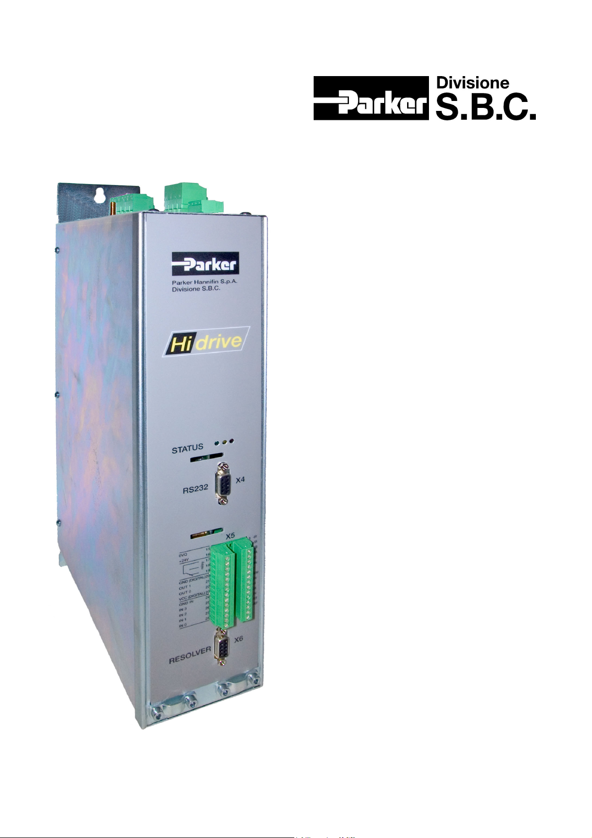
Hi-drive
Quick installation guide
rev. 0
November 2004
(software rel. 0)
Page 2

Parker Hannifin S.p.A. – S.B.C. Division quick installation guide Hi-drive
R
R
T
R
R
R
R
T
R
R
R
R
T
IMPORTANT INFORMATION
A
WWA
NNIINNGG
people and even be lethal. It is prohibited to approach and/or to violate whichever part of the converter; that
would involve also the immediate invalidation of the warranty (of one year).
O
IIMMPPO
TTAAN
The customer must study with attention the contents of the present manual before the installation/use. The
installation, the start up and the maintenance are permitted exclusively to persons capable, trained and qualified
to use of industrial electronic equipment. These persons must be acquaintance of electric/mechanical risk
associates to products for control the motion connected to mains power.
O
IIMMPPO
TTAAN
Unexpected or unsuspected movements could be taken place especially during the development of control
programs: to preview the opportune emergencies and don’t touch the parts of the machine in motion.
The Hi-drive must be installed in a protected atmosphere. Before using whichever type of drive or motor it is
important to analyze to all aspects of the application verifying the characteristics on catalogues currents. The
user is the only responsible for the final decision approximately the system and components to use.
Parker Hannifin –S.B.C. Division declines every responsibility deriving from an use of the product not in
compliance with the instruction described in the present manual.
A
WWA
NNIINNGG
Before switching on power for electrical units, all housing and motor must be permanently grounded according
to the connection diagram. This applies even for brief tests. Use a copper conductor with at least 10mm
section over its entire course for the protective connection (PE)! European countries: see EN61800-5-1, section
4.2.5.4.2. USA: see National Electrical Codes (NEC, National Electrical Manufacturers Association (NEMA),
and local bulging codes. The user of this equipment must maintain the above noted instructions at all times.
O
IIMMPPO
TTAAN
The present user’s manual refers to the version standard of the converter.
The information contained in this handbook, included technical methods and described concepts are owners of
Parker Hannifin – S.B.C. Division – EME Division and its dealership s and cannot be copier or be used without
expressed authorization. Parker Hannifin S.B.C. Division engages itself to a constant modernization of the own
products and the right is reserved to modify anytime produced and manual of use without warning obligation.
No part of this manual can be reproduced in whichever shape without authorization of Parker Hannifin S.B.C.
Division.
The performance of “Hi-drive” converter is guaranteed only with synchronous motors with permanent magnets MB
Upon request, Parker Hannifin S.p.A. Divisione S.B.C.offers training courses.
THIS QUICK INSTALLATION GUIDE REFERS TO THE STANDARD PRODUCT AND DOES NOT REPLACE
THE MORE COMPLETE VERSION OF THE OPERATOR'S MANUAL. BEFORE USING THE PRODUCT,
ALWAYS CAREFULLY READ THE COMPLETE OPERATOR'S MANUAL, A COPY OF WHICH IS AVAILABLE
ON THE CD-ROM ATTACHED TO THE SUPPLY. PARKER HANNIFIN SpA S.B.C. DIVISION DISCLAIMS ALL
LIABILITY FOR ANY TYPE OF DAMAGE DERIVING FROM INAPPROPRIATE PRODUCT USE.
Immunity:
EN50082-1* / EN61000-6-2 Basic immunity specifications
IEC1000-4-2 level 3 Immunity for electrostatic charge
IEC1000-4-3 level 3 Immunity for electromagnetic field
IEC1000-4-4 level 4 Immunity for fast transmission burst
EN50081-1* / EN61000-6-4 Basic specifications for radio interference
EN55011 group 1, class A Limits of measurement for radio interference
EN55011 group 1, class B* Limits of measurement for radio interference
Safety regulation EN50178
Low voltage regulation 73/23/CEE modified by 93/68/CEE
Applied regulation EN60204-1
* Conformity to the residential or industrial environment depends on the installation.
The product Hi-drive, described in this handbook, doesn’t contain accessible parts to the
customer, to open it or to try to approach the inner components could cause an irreparable
fault. Some internal circuits are subject to voltages that could create serious hazards for
The user shall be responsible for ensuring that installation is done in accordance with the
T
N
applicable Work Safety regulations.: the breach could cause to damages to things and/or
persons.
High equipment to performance for the control like the Hi-drive, is able to produce to
T
N
movements many expresses to forces high.
High leakage current! Risk of electric shock!
Leakage current exceeds 3.5mA.
Do not touch the surfaces of the mechanism when this is operating or afterwards, because
T
N
the temperatures of some surfaces could touch 85°C (185°F).
and SMB Series that have been manufactured by us.
Conformity to EMC standards
Compatibility:
Safety
2
cross
Page 2 of 12
Page 3
Parker Hannifin S.p.A. – S.B.C. Division quick installation guide Hi-drive
This symbol is an invitation to refer to the more detailed information in the
integral version of the operator's manual attached to the supply or which
can be downloaded from www.sbcelettronica.com
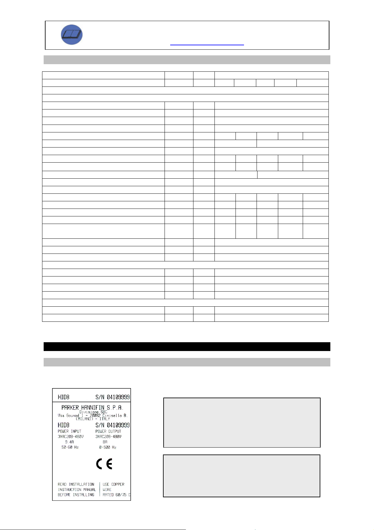
1.1 Hardware specifications
Description Symbol UdM Type of drive
Hi-Drive type 2 5 8 16 25
POWER
Mains supply: three-phase or single-phase or D.C.
Three-phase rated voltage V
Single-phase rated voltage V
D.C. V
Frequency of the A.C. supply f
V~
mains
V~
mains
dc
mains
V=
Hz 50…60 ±5%
200 – 10% $ 480 +10%
200 – 10% $ 277 +10%
245 $ 744
Load installed for continuous service S KVA 1,4 3,5 5,6 11,2 17,5
PWM switchover frequency
PWM switchover frequency (default) f
Continuative current at output (*) ±2% I
Peak current at output 2s (*) ±2%
Current derating in case of fsw>f
Current derating @ 480V
Maximum frequency at output f
(selectable)
Kv p.u. 0,9
mains
f
Kf p.u. 0,7 -
def
kHz 8-16 8
sw
kHz 8
def
Arms 2 5 8 16 25
cont
Arms 4 10 16 32 50
I
peak
Hz 0÷500
out
Power stage losses Ploss W 30 75 120 220 350
Volumetric capacity of internal fans Q m3/h 32 47 63 168 168
Braking resistance Rb Ohm 200 90 75 40 27
Continuous internal braking power Pb
Braking power peak 790VDC Pb
Continuative power P
Overvoltage cutout (OV) V
Undervoltage cutout (UV) V
W 75 75 120 180 180
cont
W s 3120 1 6935
peak
out
ovl
und
W See diagrams
V 870
V 70% * √2 *V
0,7
8320
0,5
15600
0,2
mains
23115
0,15
CONTROL
D.C. power supply Vcc V= 24 (0%…+10%)
Maximum ripple Vcc
V Do not exceed range
ripple
Max power input Icc A= 2
Power input Pcc W 30
PARKING BRAKE
Power supply voltage Vs V= 24 ±10%
Max current Is A= 2
(*) data applied according to the default switchover frequency and 400 V power voltage; higher values derate the
output current.
2 INSTALLATION
2.1 Identification
Five available models: HID2, HID5, HID8, HID16 and HID25, where the number corresponds to the rated
current (in A) which the drive can dispense.
Page 3 of 12
The installation and cabling operations must be done
when there is absolutely no voltage in the entire electric
cabinet. Make sure that the power switch on the converter
is cut off from the emergency circuit. The first time the
cabinet is powered up, qualified technical personnel must
be present.
This is a product of the restricted sales distribution class
according to EN61800-3.
In a domestic environment this product may cause radio
interference in which case the user may be required to
take adequate measures.
Page 4
Parker Hannifin S.p.A. – S.B.C. Division quick installation guide Hi-drive
T
T
T
T
T
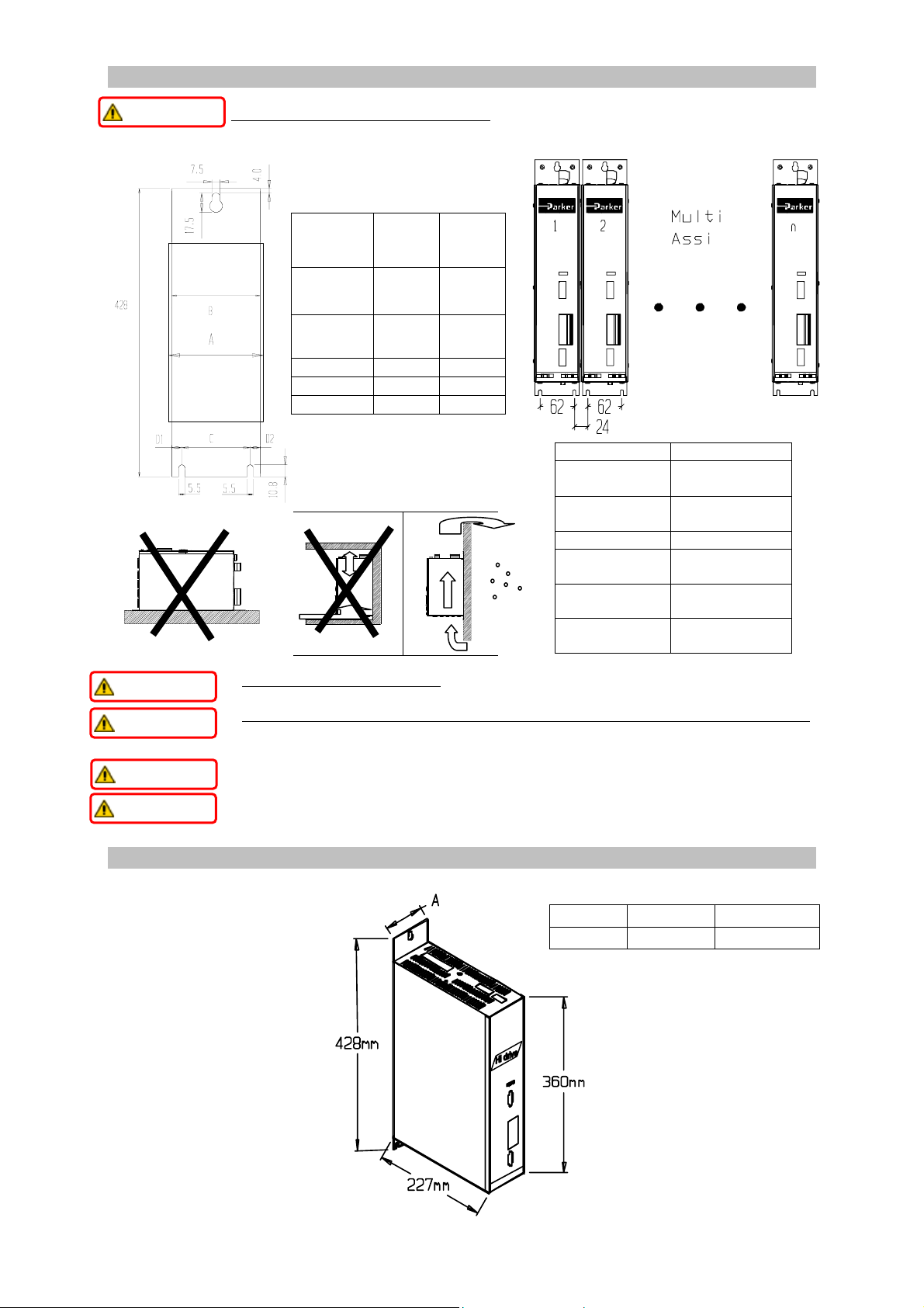
2.2 Assembly
T
IIMMPPOORRTTAAN
The rear supporting plate features special reamed holes (see illustration).
N
Do not install in hazardous environments.
• FIT IN VERTICAL POSITION (power terminal board at top).
T
IIMMPPOORRTTAAN
IIMMPPOORRTTAAN
N
• To ensure drive cooling, leave a free space above, below and in front of at least 100 mm
T
N
The illustration shows how hot air cooling must be done in an external environment, to
avoid damage caused by the formation of condensation.
• The flow of air entering the converter must not come from or pass through other heat
T
IIMMPPOORRTTAAN
IIMMPPOORRTTAAN
N
T
N
source parts.
• Fit a suitable ventilation filter inside the switchboard.
2.3 DIMENSION
Type of
drive
HID2
HID5
HID8
HID16
HID25
A
(width
frame)
B
(width
plate)
C
D1
D2
87 122
80 115
62 79,5
9 26,5
9 9
Measurements expressed in mm.
Tolerance ±1.5 mm.
Characteristics Description
Storage
temperature
Room
temperature
-20°C $ +65°C
(-4°F $ 149°F)
0°C $ 45°C
(32°F $ 113°F)
Room humidity < 85 %
Max installation
altitude
Degree of
protection
Degree of
pollution
1000 m asl
IP20
2 or below
.
size HID2-5-8 HID16-25
A
87mm 122mm
Page 4 of 12
Page 5
Parker Hannifin S.p.A. – S.B.C. Division quick installation guide Hi-drive
3 WIRING CONNECTIONS
• Wire up the panel/drive/motor in accordance with the instructions in the operator's manual and applicable
safety regulations. In case of any doubts, contact our After-Sales Service.
• Check the correct dimensioning of the drive/motor. Compare the rated voltages and currents.
• Make sure the maximum power voltage to terminals L1, L2, L3 does not exceed the specifications (see
EN60204-1, section 4.3.1) to avoid damaging the drive.
• Make sure the system is properly earthed.
• The user is responsible for the cutout fuses on the AC or DC supply of the converter.
• Be careful of the cable cross sections; refer to the "connections" table and ensure conformity with IEC227-2.
• The cables connected to the drive by means of the terminal board should not be strengthened by soldering
Sn-Pb (EN60065, art.15.3.5).
• DO NOT
remove the power connections from the drive when this is energised.
• After interrupting the power supply and after the converter has been switched off, allow at least 5 minutes to
pass before disconnecting the motor leads from the drive, as hazardous voltages could persist.
• DO NOT
open the converter. This could be hazardous and immediately invalidate the warranty.
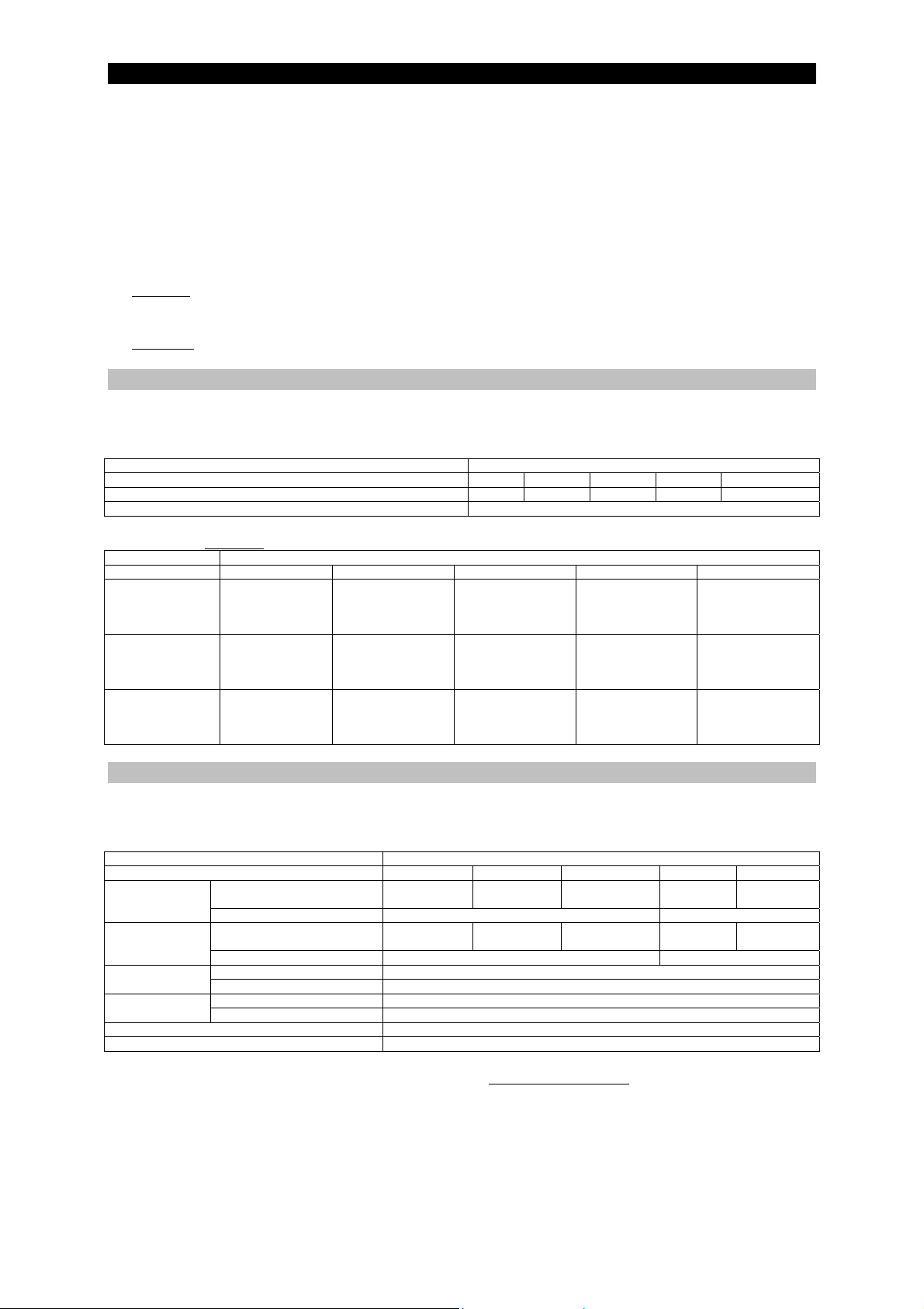
3.1 Protection devices
The drive can be connected to an A.C. mains having at most 5kA of short-circuit current and maximum voltage
of 480V. The drive is without integrated overload protection.
Table for dimensioning the fuses:
Mechanism size 2 5 8 16 25
Fuse size (delayed) on AC mains 6A rit 10A rit 16A rit 20A rit 50A rit
Fuse sizes on control supply VDC 3.15A
Type of Hi-drive
Instead of the fuses, a thermal magnetic circuit breaker can be used with the same effectiveness as the fuses.
Table for using ultra fast
Drive type HID2 HID5 HID8 HID16 HID25
AC mains
(three fuses)
Braking
(two fuses)
DC Bus
(two fuses)
fuses to UL standards:
Bussmann
FWP10A14F
Ferraz-Shawmut
A70P10-1
Bussmann
FWP10A14F
Ferraz-Shawmut
A70P10-1
Bussmann
FWP10A14F
Ferraz-Shawmut
A70P10-1
Bussmann
FWP20A14F
Ferraz-Shawmut
A70P20-1
Bussmann
FWP20A14F
Ferraz-Shawmut
A70P20-1
Bussmann
FWP20A14F
Ferraz-Shawmut
A70P20-1
fuse type
Bussmann
FWP30A14F
Ferraz-Shawmut
A70P30-1
Bussmann
FWP20A14F
Ferraz-Shawmut
A70P30-1
Bussmann
FWP30A14F
Ferraz-Shawmut
A70P30-1
Bussmann
FWP-50B
Ferraz-Shawmut
A70P50-4
Bussmann
FWP30A14F
Ferraz-Shawmut
A70P30-1
Bussmann
FWP-50B
Ferraz-Shawmut
A70P50-4
Bussmann
FWP-60B
Ferraz-Shawmut
A70P60-4
Bussmann
FWP-35B
Ferraz-Shawmut
A70P35-1
Bussmann
FWP-60B
Ferraz-Shawmut
A70P60-4
3.2 Wiring harness
The motor cable must be shielded. The mains power cables must not necessarily be shielded. In the case of
cable chains, cables for mobile installation will have to be chosen.
Sections table:
Mechanism size HID2 HID5 HID8 HID16 HID25
MOTOR
(X2 terminal)
MAINS
(X1 terminal)
Signal
(X5 terminal)
Parking brake
Maximum length of motor cables 60 m
Max cable capacity < 150 pF/m
The RESOLVER cable features 4 x 0.22 mm
general shielding. The lead-lead capacity for the length used must not exceed 10nF.
60 m.
The 24V= power supply must be dedicated to the drive only, and not shared with other devices (contactors,
brake relays, solenoid valves, etc.). Prefer a shielded cable.
The cables used for analogue signals (minimum section 0.22 mm
Also use shielded cables for the digital inputs and outputs.
CABLE Type of Hi-drive
2
1.5 mm
Section
Tightening torque 0.5 – 0.6 Nm (M3) 1.2 Nm (M4)
Section
Tightening torque 0.5 – 0.6 Nm (M3) 1.2 Nm (M4)
Section
Tightening torque 0.22 – 0.25 Nm (M2)
Section 1 mm2 (AWG16)
Tightening torque 0.5 – 0.6 Nm (M3)
2
(AWG14)
2
2 mm
(AWG14)
pairs of minimum section, twisted and shielded individually plus
1.5 mm2
(AWG14)
2 mm2
(AWG14)
2.5 mm2
(AWG12)
2.5 mm2
(AWG12)
0.22 $ 1 mm
2
(AWG16)
4 mm2
(AWG8)
4 mm2
(AWG8)
6 mm2
(AWG8)
6 mm2
(AWG8)
The max acceptable length is
2
) must feature twisted and shielded pairs.
Page 5 of 12
Page 6
Parker Hannifin S.p.A. – S.B.C. Division quick installation guide Hi-drive
T
T
)
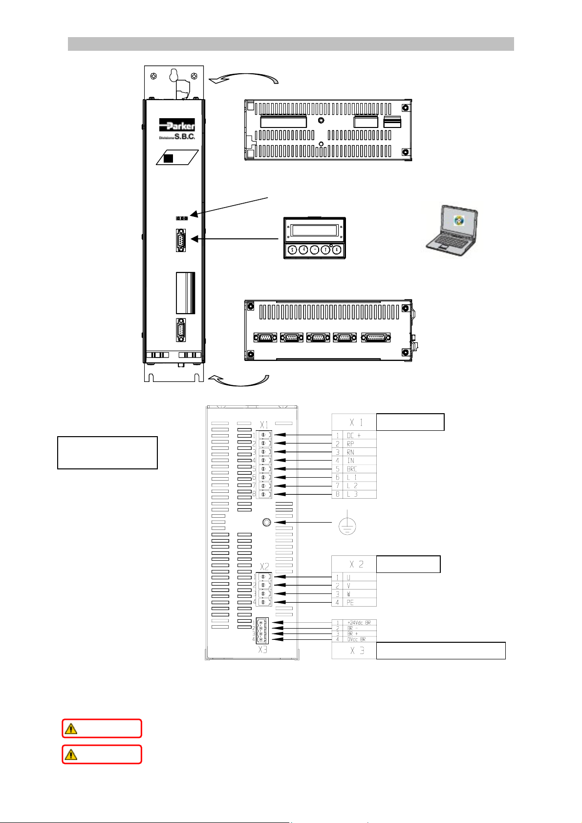
3.3 Connector layout
Hi drive
X4
X5
X6
X1 –
mains
Status Led (*
Module Display/Keypad
(optional)
X11
X8
X9 X10
X2
motor
otherwise
X7
X3
brake
Top panel
“MOTIONWIZ”
on CD-Rom enclosed in stock
Lower panel
MAINS
Power terminal (top
panel)
MOTOR
PARKING BRAKE
(*) The yellow and green LEDs are active if, when the drive supply is connected (24Vdc), the drive
electronics is operating.
The red LED, called “STATUS” provides a series of information on the state of the converter:
- off the converter is disabled without active alarms.
- on the converter is enabled: the drive is in RUN mode
- flashing with interval between the 2 series of flashes, the converter is disabled and an
T
IIMMPPOORRTTAAN
IIMMPPOORRTTAAN
N
alarm has tripped; the tripped alarm can be identified by counting the number of flashes
T
N
between two intervals.
- Continuous fast flashing indicates the command I
2
t is active, the converter remains
enabled.
Page 6 of 12
Page 7
Parker Hannifin S.p.A. – S.B.C. Division quick installation guide Hi-drive
T
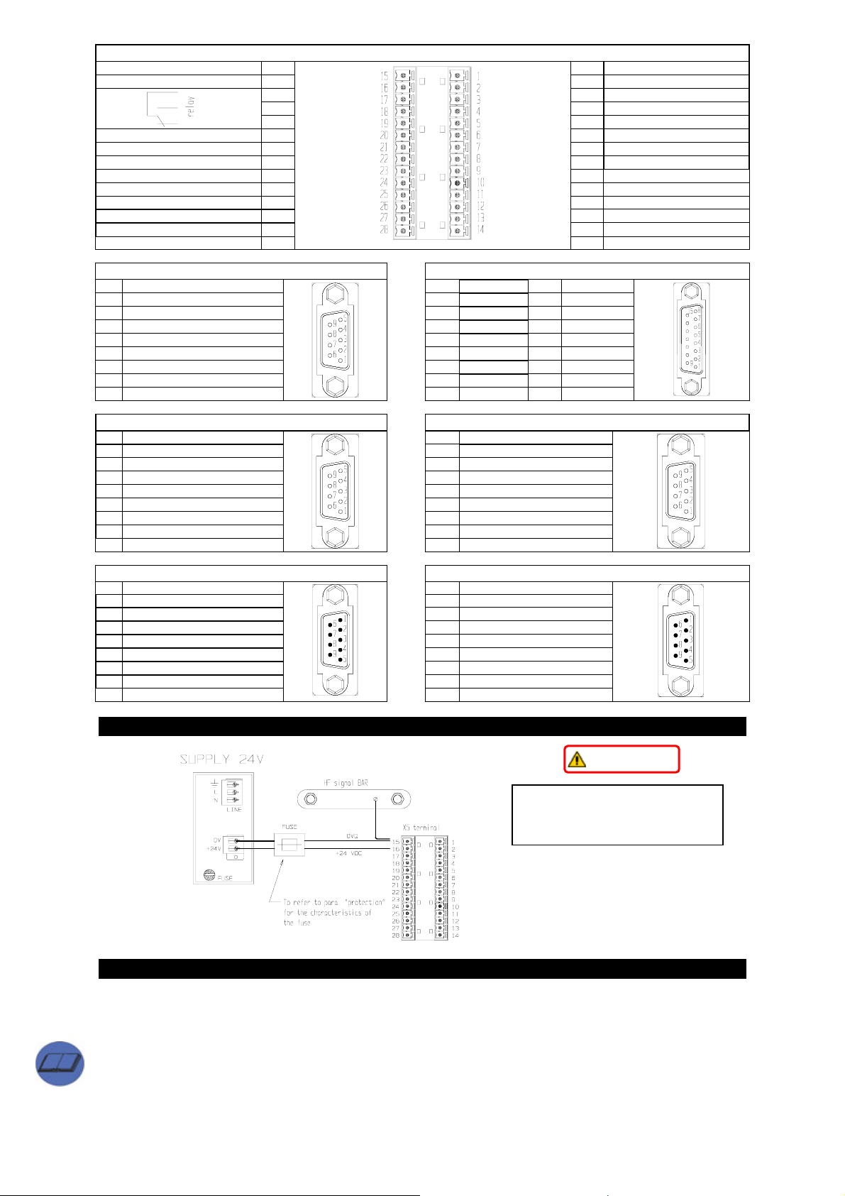
X5 : terminal connection
0VQ drive supply 15 1 – SR drive enabling
+24V drive supply 16 2 + SR drive enabling
GND (DIGITAL) 20 6 0VA
OUT 1 21 7 MON 2
OUT 0 22 8 MON 1
VCC (DIGITAL) 23 9 0VA
GND IN 24 10 – AX
IN 3 (ENCODER IN) 25 11 + AX
IN 2 (ENCODER IN) 26 12 0VA
IN 1 27 13 – REF
IN 0 28
17 3 SC B
18 4 SC A
19 5 N.C.
14 + REF
X6 : “resolver” (DB9 female) X7 : “sincos” (DB15 female)
1 PTC - 1 PTC - 10 Ve
2 A GND 2 SHIELD 11 SENSE 3 ECC - 3 A GND 12 CLK 4 SIN - 4 SENSE + 13 DATA 5 COS - 5 CLK + 14 B 6 PTC + 6 DATA + 15 A 7 ECC + 7 B +
8 SIN + 8 A +
9 COS +
9 PTC +
X8 : “RS422/485” (DB9 female) X9 : “encoder input” (DB9 female)
1 TX422 + 1 EIN A +
2 RX422 + 2 EIN A 3 TX422 - 3 EIN B +
4 RX422 - 4 EIN B 5 SHIELD 5 EIN C +
6 Termination 6 EIN C 7 N.C. 7 0VF
8 N.C. 8 SHIELD
9 0V F
9 +5V F
X10 : “encoder output” (DB9 male) X11 : “CAN” (DB9 male )
1 EOUT A + 1 N.C.
2 EOUT A - 2 CANL
3 EOUT B + 3 GND CAN
4 EOUT B - 4 Reserved
5 EOUT C + 5 SHIELD
6 EOUT C - 6 Reserved
7 0VF 7 CANH
8 Reserved 8 N.C.
9 Reserved
9 Reserved
4 24V= SUPPLY
T
IIMMPPOORRTTAAN
N
The 24 V powers the drive
electronics and therefore
controls drive switch on and off.
5 CONNECTION TO POWER MAINS
Two modes that can be selected with Pr39.0:
- programme 0 for three-phase mains supply 180V~ MIN to 528V~ MAX or single-phase at 305V~ MAX.
- programme 1 for D.C. supply - 254V= MIN to 744V= MAX. Enter value in Pr21, save, switch off and then
back on.
Æ A third possibility exists - low-voltage supply (see Operator's Manual).
With both the D.C. and the A.C. supply, the undervoltage threshold is set not below 70% of VMIN (254V= or
180V~). If the bit b39.8 is set at one, upon the return of the mains voltage, the undervoltage alarm is
automatically reset.
Page 7 of 12
Page 8
Parker Hannifin S.p.A. – S.B.C. Division quick installation guide Hi-drive
T
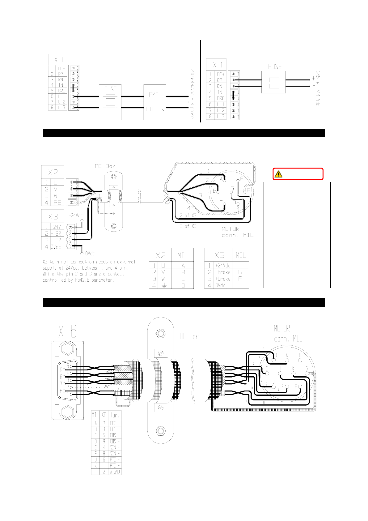
In the case of D.C. current supply, the maximum voltage must be 744V=. The connection terminals are in
terminal board X1 between the terminals RP (positive) and RN (negative).
Direct connection to D.C. mains (three-phase) Connection for D.C. current
6 MOTOR
Before entering the motor data parameter Pr31 must be defined: write “0” for brushless motor (default) or “1”
for asynchronous motor.
T
IIMMPPOORRTTAAN
N
On the terminal board
X3, the output that
powers the parking
brake (pin 2 and 3) is
controlled through the
internal bit of the drive
as a type ON/OFF
command.
Important:
in all
operating conditions,
the user shall be
responsible for
controlling the brake
release-on control.
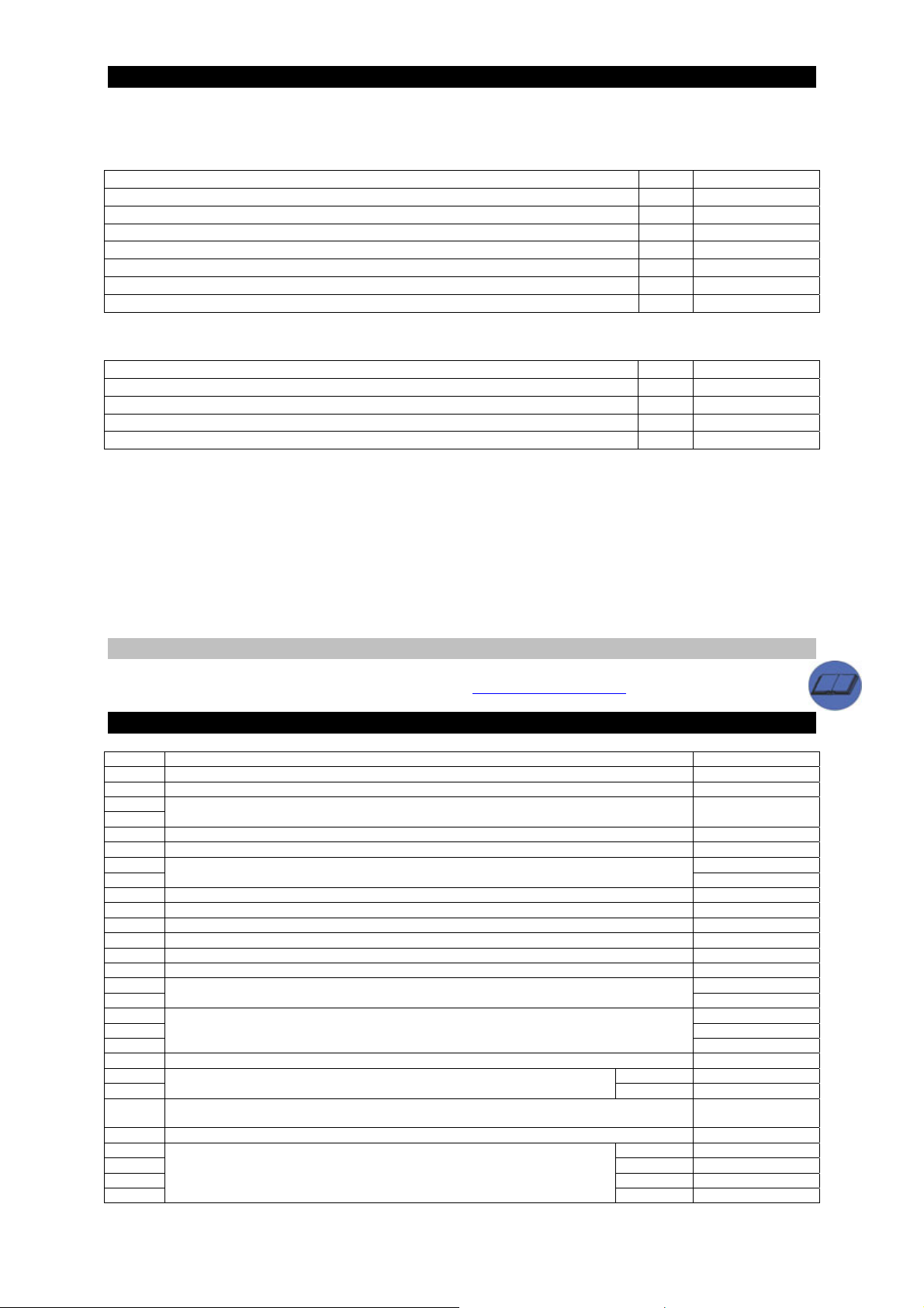
7 Resolver
When the resolver is connected, do not use the Less Wiring enc. or the incremental encoder in X7.
Page 8 of 12
Page 9
Parker Hannifin S.p.A. – S.B.C. Division quick installation guide Hi-drive
8 FEEDBACK ( FBK )
Types:
-FBK A, resolver only (only read if also selected as speed loop feedback).
-FBK B, with the Pr62, the following systems can be selected:
FBK B Pr62 INPUT ON
Encoder Sincos + EnDat interface 0 X7
Encoder Sincos 1 X7
Encoder Less Wiring (**) 2 X7
5V Line Driver 422 quadrature signals (incremental encoder) (**) 3 X7
5V Line Driver 422 frequency/direction signals (*) 4 X7
24V Push-Pull quadrature signals (IN2 and IN3) (*) 5 X5
24V Push-Pull frequency/direction signals (IN2 and IN3) (*) 6 X5
-FBK C, can support through selection of parameter Pr63
FBK C Pr63 INPUT ON
5V Line Driver 422 quadrature signals (incremental encoder) 3 X9
5V Line Driver 422 frequency/direction signals (*) 4 X9
24V Push-Pull quadrature signals (IN2 and IN3) (*) 5 X5
24V Push-Pull frequency/direction signals (IN2 and IN3) (*) 6 X5
(*) these signals cannot be used as feedback on the position loop, but can be used as encoder input counters.
(**) when the resolver is connected to X6, do not connect the Less Wiring encoder and the incremental encoder
to X7.
To the connector, a variable supply is available with voltage that can be set at 5, 8 or 12V=, by means of a
parametric switch. In the case of 5 and 8 V voltages, these can be regulated with a feedback by means of a
sensing pair to offset any voltage drops of the cables. In the case of 12V, the feedback is internal and any voltage
drop cannot be offset. Bit Pb64.0 indicates whether the sensing function is on, otherwise the voltage set in open
loop is regulated.
To the in encoder connector, a fixed isolated voltage of 5V is available.
8.1 Encoder connection
Refer to the diagrams in the Operator's Manual at website www.sbcelettronica.com
.
9 INPUT AND OUTPUT : X5 TERMINAL CONNECTIONS
PIN DESCRIPTION
1 GND: for hardware enabling. 0V DC
2 Input: hardware enabling. Safety relay supply (optional). Voltage: 24V DC
3
4
5 N.C.
6 Common: programmable output 0V
7 MON 2: 0 ÷ 10V DC
8
9 Common: anal. input. Aux. Ref. 0 V
10 - AX: analogue signal dedicated to auxiliary reference – input 0 ÷ 10V DC
11 + AX: analogue signal dedicated to auxiliary reference – input 0 ÷ 10V DC
12 Common: anal. input Main Ref. 0 V
13 - REF: main reference analogue signal – input 0 ÷ 10V DC
14 + REF: main reference analogue signal – input 0 ÷ 10V DC
15 0V DC
16
17 Common 0V DC
18 N.O.: 24V DC
19
20 Digital output supply (together with VDC – term. 23) 0V DC
21 Pb91.1 OUT 1: 5 ÷ 24V DC
22
23
24 Input common 0V dc
25 Pb90.3 IN 3: 24V DC
26 Pb90.2 IN 2: 24V DC
27 Pb90.1 IN 1: 24V DC
28
Output: two programmable outputs are available to display the parameters (see “programmable
Relay outputs: the internal relay controls two outputs for the external and is associated with the
Digital output: the output voltage is determined by the connected supply. Associated
Digital output supply: the output voltage can be determined according to the given supply (together
Inputs: four different inputs are available and are matched with binary parameters
Output: safety relay (when fitted). Contact
outputs” paragraph).
Drive supply (see chap. “converter supply”)
parameter bin. Pb91.2
18: N.O. contact - 19: N.C. contact
binary parameters Pb91.0 e .1
with GND term. 20)
Pb90.0 $ Pb90.3
Pb91.0 OUT 0: 5 ÷ 24V DC
Pb90.0 IN 0: 24V DC
MON 1: 0 ÷ 10V DC
24V DC
N.C.: 24V DC
5 ÷ 24V DC
Page 9 of 12
Page 10

Parker Hannifin S.p.A. – S.B.C. Division quick installation guide Hi-drive
A
10 FIRST CONVERTER START-UP
The drive is supplied from the factory with default programming.
Remember that the Hi-drive can control brushless synchronous or asynchronous motors. Before entering the
motor data, programme Pr31: write “0” for brushless motor (default condition), “1” for asynchronous motor.
At this point the mechanism must be set with the fundamental parameters to characterise the connected motor
(motor plate data). The fundamental parameters are:
Pr29 Number of motor poles N
Pr32 nominal motor speed r.p.m.
Pr33 rated motor current (eg. 2.5A, write 2.5) A
Pr46 motor phase-phase resistance (eg. 1.8Ω, write 1.8) ohm
Pr47 motor phase-phase inductance (eg. 2.6mH, write 2.6) mH
Pr60 number of resolver poles N
In the case of an asynchronous motor, the previous data must be completed with the following parameters:
Pr45 basic speed r.p.m.
Pr48 sliding r.p.m.
Pr49 magnetisation current A
synchronous motor
Pr32 limit speed of motor r.p.m.
After setting the parameters for motor characterisation, the operator must give the data saving command,
Pb42.15 (with drive disabled) and start the mechanism again. The drive will calculate the correct values of Pr2,
Pr3, Pr16, Pr17, Pr18 and Pr19. The gain calculation is done if the drive is in default condition.
To change the entered parameters, put bit Pb42.1=1. The drive, at this point, again asks for the default
parameters (alarm 15). After data entering, save and start the drive again. The parameters Pr2, Pr3, Pr16, Pr17,
Pr18 and Pr19 will be recalculated according to the entered values.
10.1
First Hi-drive start-up
Below, the steps are shown to be carefully followed during first converter start-up.
1) Connect the motor to the converter, carefully following the manual diagrams.
2) Make sure the converter is disabled.
3) Start the converter.
4) Make sure no alarm has tripped.
5) Set the analogue reference at 0 V (pin 13, 14 of terminal board X5), and enable the converter (24V at the
pin that enables the drive).
6) Now the motor shaft must be stopped; when the analogue reference voltage changes, the motor speed
must change proportionately. If it does not, check the wiring harness.
The converter is made with default values already set.
10.2
Setting the default parameters
To set the default parameters (which change all previously set parameters) proceed as follows:
- start the converter
- disable the converter by means of software command (Pb40.9=0) or via hardware (before starting the
converter)
- set Pb39.13=0
- give the command Pb42.12=1, which enables drive default parameter loading
- enter the fundamental parameters (motor plate data, see para. 3.2)
- save the setting with commands Pb42.14 e Pb42.15 (the drive must be disabled)
- stop and start the drive again.
11 USE OF KEYBOARD (OPTIONAL)
S, SHIFT, is used in combination with the other keys to enable the cursor to move inside the fields:
o Together with key T, movement inside the fields is made in the opposite direction (anticlockwise).
o Together with key + o – to move the cursor inside the field on a figure with greater or less "weight".
+, increases the datum shown by the cursor; if PLC instructions.
–, decreases the datum shown by the cursor; if PLC instructions.
T, the purpose of this key is to change the field shown by the cursor.
E, ENTER, confirms datum entering or change. The changed or entered datum or instruction must be saved
before changing the display page, otherwise the change made will be lost. IMPORTANT: the instructions can
also be changed when the Pico-PLC is running (Pr39.13=1), and so before changing anything, it is best to stop
the Pico-PLC.
Page 10 of 12
Page 11
Parker Hannifin S.p.A. – S.B.C. Division quick installation guide Hi-drive
12 Alarms
Pr23 Alarm Remedies
0 No alarm
1 Overvoltage Check the three-phase power line.
Check the braking line and braking resistance
Check the application
2 Undervoltage
3 Overcurrent Check any mechanical impediments and correct motor size for required use.
4 FBK speed loop
error
5 Motor PTC alarm -Check the PTC connection cable.
6 Power module
overheating
7 External alarm Depends on application (see PicoPLC program)
8 Auxiliary alarm Depends on application (see PicoPLC program)
10(*) Check sum PLC Set the default parameters, save, switch back on and reprogramme the drive
11(*) Check sum param. Set the default parameters, save, switch back on and reprogramme the drive
15 Default parameters Set the default parameters, save and switch back on
21 24VDC
undervoltage
22 Environment
overheating
24 Braking transistor
cutout
25(**) Wrong FBK speed
loop initialisation
26(**) Wrong FBK
position loop
initialisation
28 FBK position loop
error
I2T Current restriction
2
(I
T) - “the red LED
flashes
continuously”
(*) only reset after default loading and new saving.
(**) cannot be reset until next switch-on.
Check the three-phase power line.
Check motor connections and any short-circuits between phase-phase and phaseearth.
Check the length and type of motor cable used.
Make sure a mains filter is not connected on the motor!
Check the speed loop connections and the connectors from both sides (drivemotor).
-If the alarm persists, disable the drive, interrupt power to the motor, disconnect
the power supply to the drive (24VDC). Disconnect the PTC connector from the
drive, and make a connection short-circuiting the PTC (between PTC+ and PTC-)
on the terminal board of the drive itself.
Power the drive (24VDC). If the alarm continues, the drive is faulty, otherwise
the PTC on board the motor is faulty (after completing the test, remove the
connection short-circuiting the PTC)
Check the cooling fans and any blockages/restrictions in air flow.
Check the braking cycle.
Check the room temperature of the switchboard where the drive is fitted and
outside room temperature.
The drive power voltage is below minimum threshold: voltage too low.
Check the cooling fans and any blockages/restrictions in air flow.
Check the room temperature of the switchboard where the drive is fitted and
outside room temperature.
Braking resistance in short circuit. If an external braking resistance is connected
to the drive, check its condition and wiring harness.
Check the FBK speed settings.
Check the FBK speed connection.
Check the settings of the position FBK.
Check the connection of the position FBK.
Check the connections of the position loop and the connectors on both sides
(drive-motor).
The drives goes in I²T due to an overload (more power is required than that being
supplied). Check:
-The wiring between the drive and the motor (there must be no switched-over
phases). Above all mind the motors with terminal board rather than connector: it
is easy to make a mistake. Make sure you keep to the wiring diagrams.
- Mechanical sizing
ISBN0411301550
Page 11 of 12
Page 12
MI HI 00 11/04 EN
 Loading...