

Page 1
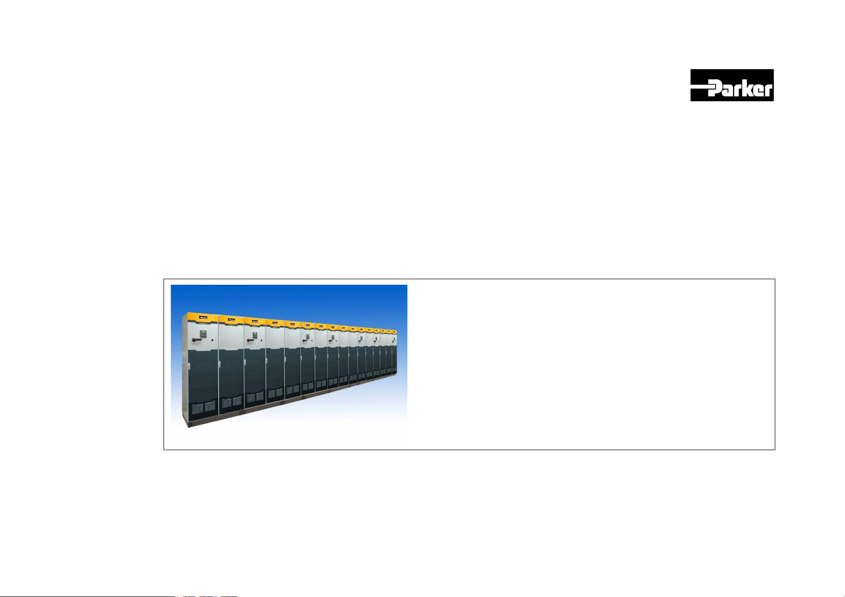
HA471664U001:AC890 Engineering Reference
Product Manual : AC890PX
HA471664U001 Issue 5
Compatible with Software Version 3.4
2009 Parker SSD Drives, a division of Parker Hannifin Ltd.
All rights strictly reserved. No part of this document may be stored in a retrieval system, or
transmitted in any form or by any means to persons not employed by a Parker SSD Drives
company without written permission from Parker SSD Drives, a division of Parker Hannifin Ltd .
Although every effort has been taken to ensure the accuracy of this document it may be necessary,
without notice, to make amendments or correct omissions. Parker SSD Drives cannot accept
responsibility for damage, injury, or expenses resulting therefrom.
WARRANTY
Parker SSD Drives warrants the goods against defects in design, materials and workmanship for
the period of 24 months from the date of manufacture, or 12 months from the date of delivery
(whichever is the longer period), on the terms detailed in Parker SSD Drives Standard Conditions
of Sale IA500504.
Parker SSD Drives reserves the right to change the content and product specification without
notice.
Page 2

&
R
S
New Courtwick Lane, Littlehampton, West Sussex BN17 7RZ
Tel: +44 (0)1903 737000 Fax: +44 (0)1903 737100
UK Head Office: Parker SSD Drives
S E R V I C E
R E P A I
C E N T R E
CANADA
Parker Hannifin Canada
Motion and Control Division
160 Chisholm Drive
Milton, Ontario L9T 3G9
Tel: +1 (905) 693-3000
Fax: +1 (905) 876-1958
GERMANY
Parker Hannifin GmbH
Von-Humboldt-Strasse 10
64646 Heppenheim
Tel: +49 (6252) 798200
Fax: +49 (6252) 798205
CHINA
Parker Hannifin Motion & Control
(Shanghai) Co. Ltd.
280 Yunqiao Road,
JinQiao Export Processing Zone,
Pudong district, Shanghai 201206
Tel: +86(21)5031 2525
Fax: +86(21)5854 7599
ITALY
Parker Hannifin SPA
Via c. Gounod, Cinisello Balsamo
1-200092, Milano
Tel: +39 (0236) 1081
Fax: +39 (0236) 108400
FRANCE
Parker SSD Parvex
8 Avenue du Lac
B.P. 249
21007 Dijon Cedex
Tel: +33 (0)3 80 42 41 40
Fax: +33 (0)3 80 42 41 23
USA
Parker Hannifin Corporation
SSD Drives
9225 Forsyth Park Drive
Charlotte
North Carolina 28273
Tel: +1 (704) 588 3246
Fax: +1 (704) 588 3249
Local availability and service support also in:
Argentina ● Australia ● Austri a ● Bangladesh ● Belgium ● Brazil ● Chile ● Colombia ● Costa Rica ● Cyprus
Czech Republic ● Denmark ● Ecuador ● Egypt ● Finland ● Greece ● Hong Kong ● Hungary ● India ● Indonesia
Iran ● Ireland ● Israel ● Japan ● Jordan ● Kenya ● Korea ● Kuwait ● Lithuania ● Malaysia ● Netherlands
New Zealand ● Nigeria ● Norway ● Peru ● Philippines ● Poland ● Portugal ● Quatar ● Romania ● Russia
Saudi Arabia ● Singapore ● Slovenia ● Slovakia ● South Africa ● Spain ● Sri Lanka ● Sweden ● Switzerland
Taiwan ● Thailand ● Turkey ● United Arab Emirates ● Vietnam ● Zimbabwe
03/05/09
www.ssddrives.com
*HA471664U001-05*
Page 3

890 Series
A C 8 9 0 P X A C D r i v e
2009 Parker SSD Drives, a division of Parker Hannifin Ltd.
All rights strictly reserved. No part of this document may be stored in a retrieval system, or transmitted in any form or by any means to persons not employed by a Parker SSD Drives
company without written permission from Parker SSD Drives, a division of Parker Hannifin Ltd . Although every effort has been taken to ensure the accuracy of this document it may be
necessary, without notice, to make amendments or correct omissions. Parker SSD Drives cannot accept responsibility for damage, injury, or expenses resulting therefrom.
WARRANTY
Parker SSD Drives warrants the goods against defects in design, materials and workmanship for the period of 12 months from the date of delivery on the terms detailed in Parker
SSD Drives Standard Conditions of Sale IA500504.
Parker SSD Drives reserves the right to change the content and product specification without notice.
HA471664U001
P
R
O
D
O
O
D
D
U
P
P
R
R
U
U
C
C
C
T
T
T
M
M
M
I S S U E 2
A
N
U
A
N
U
A
N
U
A
A
A
L
L
L
Page 4
Requirements
IMPORTANT
Please read this information BEFORE installing the equipment.
Intended Users
This manual is to be made available to all persons who are required to install, configure or service equipment described
herein, or any other associated operation.
The information given is intended to highlight safety issues, and to enable the user to obtain maximum benefit from the
equipment.
Complete the following table for future reference detailing how the unit is to be installed and used.
INSTALLATION DETAILS
Model Number
(see product label)
Unit used as a:
(refer to Certification)
Component Relevant Apparatus
Where installed
(for your own information)
Unit fitted:
Free-standing drive
Application Area
The equipment described is intended for industrial motor speed control utilising AC induction or AC synchronous machines.
Personnel
Installation, operation and maintenance of the equipment should be carried out by qualified personnel. A qualified person is
someone who is technically competent and familiar with all safety information and established safety practices; with the
installation process, operation and maintenance of this equipment; and with all the hazards involved.
Page 5
Product Warnings
Caution
Risk of electric shock
Refer to documentation
Hazards
DANGER! - Ignoring the following may result in injury
1. This equipment can endanger life by exposure to rotating
machinery and high voltages.
2. The equipment must be permanently earthed due to the high
earth leakage current, and the drive motor must be connected
to an appropriate safety earth.
3. Ensure all incoming supplies are isolated before working on
the equipment. Be aware that there may be more than one
supply connection to the drive.
4. There may still be dangerous voltages present at power
terminals (motor output, supply input phases, DC bus and the
brake, where fitted) when the motor is at standstill or is
stopped.
5. For measurements use only a meter to IEC 61010 (CAT III or higher).
Always begin using the highest range.
CAT I and CAT II meters must not be used on this product.
6. Allow at least 10 minutes for the drive's capacitors to discharge to safe
voltage levels (<50V). Use the specified meter capable of measuring up
to 1000V dc & ac rms to confirm that less than 50V is present between
all power terminals and between power terminals and earth.
7. Unless otherwise stated, this product must NOT be dismantled. In the
event of a fault the drive must be returned. Refer to "Routine
Maintenance and Repair".
Caution
Earth/Ground
Protective Conductor Terminal
Page 6
WARNING! - Ignoring the following may result in injury or damage to equipment
SAFETY
Where there is conflict between EMC and Safety requirements, personnel safety shall always take precedence.
• Never perform high voltage resistance checks on the wiring without
first disconnecting the drive from the circuit being tested.
• Whilst ensuring ventilation is sufficient, provide guarding and /or
additional safety systems to prevent injury or damage to equipment.
• When replacing a drive in an application and before returning to use,
it is essential that all user defined parameters for the product’s
operation are correctly installed.
EMC
• In a domestic environment this product may cause radio interference
in which case supplementary mitigation measures may be required.
• This equipment contains electrostatic discharge (ESD) sensitive
parts. Observe static control precautions when handling, installing
and servicing this product.
• All control and signal terminals are SELV, i.e. protected by double
insulation. Ensure all external wiring is rated for the highest system
voltage.
• Thermal sensors contained within the motor must have at least
basic insulation.
• All exposed metalwork in the Inverter is protected by basic
insulation and bonded to a safety earth.
• RCDs are not recommended for use with this product but, where
their use is mandatory, only Type B RCDs should be used.
• This is a product of the restricted sales distribution class according
to IEC 61800-3. It is designated as “professional equipment” as
defined in EN61000-3-2. Permission of the supply authority shall
be obtained before connection to the low voltage supply.
Page 7
CAUTION!
APPLICATION RISK
• The specifications, processes and circuitry described herein are for guidance only and may need to be adapted to the user’s specific
application. We can not guarantee the suitability of the equipment described in this Manual for individual applications.
RISK ASSESSMENT
Under fault conditions, power loss or unintended operating conditions, the drive may not operate as intended. In particular:
• Stored energy might not discharge to safe levels as quickly as
suggested, and can still be present even though the drive appears
to be switched off
A drive is a component within a drive system that may influence its operation or effects under a fault condition. Consideration must be given to:
• Stored energy • Supply disconnects • Sequencing logic • Unintended operation
• The motor's direction of rotation might not be controlled
• The motor speed might not be controlled
• The motor might be energised
Page 8

Page 9

C h a p t e r 1 : G e t t i n g S t a r t e d 1-1
C h a p t e r
G e t t i n g S t a r t e d
1
A few things you should do when you first receive the unit.
AC890PX AC Drive
Page 10

1-2 C h a p t e r 1 : G e t t i n g S t a r t e d
About this Manual
This manual is intended for use by the installer, user and programmer of the AC890PX AC Drive. It assumes a reasonable
level of understanding in these three disciplines.
NOTE Please read all Safety information before proceeding with the installation and operation of this unit.
It is important that you pass this manual on to any new user of this unit.
How the Manual is Organised
This Engineering Reference manual is organised into chapters, indicated in the header of each page. The manual is more
detailed than the relevant QuickStart manual, and so is of use to the unfamiliar as well as the high-end user.
Initial Steps
Use the manual to help you plan the following:
Installation
Know your requirements:
• certification requirements, CE/UL/CUL conformance
• conformance with local installation requirements
• supply and cabling requirements
Operation
Know your operator:
• how is it to be operated, local and/or remote?
• what level of user is going to operate the unit?
• decide on the best menu level for the Keypad (where supplied)
Programming (using the 890 DSE Configuration Tool)
Know your application:
• create/install the most appropriate Application
• enter a password to guard against illicit or accidental changes
• customise the keypad to the application
AC890PX AC Drive
Page 11

Equipment Inspection
• Check for signs of transit damage.
Refer to Chapter 9: “Routine Maintenance and Repair” for information on returning damaged goods.
• Check the unit conforms to your requirements.
Refer to Appendix E: “Technical Specifications” to check the Product Code on the rating label.
Storage
If the unit is not being installed immediately, store the unit in a well-ventilated place away from high temperatures, humidity,
dust, or metal particles.
Storage and Shipping Temperatures
C h a p t e r 1 : G e t t i n g S t a r t e d 1-3
Storage Temperature :
-25°C to +55°C
Shipping Temperature :
Packaging and Lifting
Caution
The packaging is combustible. Igniting it may lead to the generation of lethal toxic fumes.
• Save the packaging in case of return. Improper packaging can result in transit damage.
• The drive can be transported on its back. Use a safe and suitable lifting procedure when moving the unit. The drive
is fitted with four lifting rings. Refer to Chapter 3: "Installation" for the drive weights.
• Prepare a clear, flat surface to receive the drive before attempting to move it.
-25°C to +70°C
AC890PX AC Drive
Page 12

1-4 C h a p t e r 1 : G e t t i n g S t a r t e d
AC890PX AC Drive
Page 13

C h a p t e r 2 : P r o d u c t O v e r v i e w 2-1
w
C h a p t e r
P r o d u c t O v e r v i e
An introduction to the AC890PX range of products, and a quick look at the Keypads
and available plug-in Options.
2
AC890PX AC Drive
Page 14
2-2 C h a p t e r 2 : P r o d u c t O v e r v i e w
Product Range
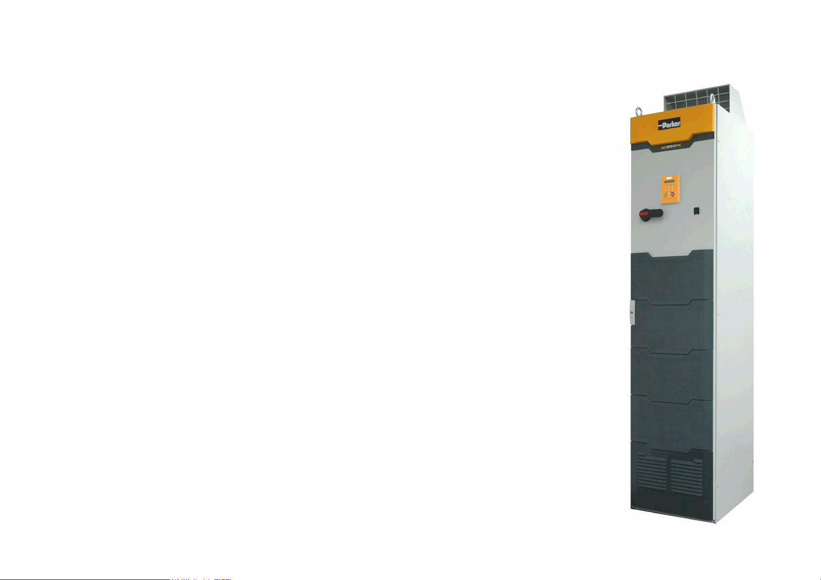
The AC890PX AC Drive is designed to control 3-phase induction or permanent magnet AC
motors, or to be used as an active front-end.
Designed as a free-standing drive, the AC890PX comprises removable modules housed in a tall
cabinet.
It is available in a range of ratings for constant torque and variable torque applications. This
dual mode feature provides a cost effective solution to general industrial applications, as well
as the control of pumps and fans.
• Supplied as a top or bottom wire entry version.
• Local control is achieved using the Keypad.
• Remote control is via the DSE 890 Configuration Tool. This gives access to parameters,
diagnostic messages, trip settings and full application programming. Other features also
become available, such as the advanced sensorless vector control scheme which gives high
torque, low speed operation; and a unique Quiet Pattern control system that minimises
audible noise from the motor.
IMPORTANT
NOTE Do not attempt to control motors whose rated current is less than 25% of the drive rated
• The unit can also be controlled remotely using configurable analogue and digital inputs and
outputs, requiring no optional equipment.
• Option Cards can be fitted to the drive to give serial communications, closed loop speed
control, and the factory-fitted dynamic braking functions.
Motors used must be suitable for inverter duty.
current. Poor motor control or Autotune problems may result if you do so.
AC890PX AC Drive
Page 15

C h a p t e r 2 : P r o d u c t O v e r v i e w 2-3
The drive is available in three voltage builds. Each build contains drives with different power ratings. Each drive has two
current ratings which are selected in software as either Heavy Duty or Normal Duty1.
The table below shows the minimum/maximum current and power for each voltage build:
400V nominal 600V nominal 700V nominal
380-480Vac
kW ratings @ 400Vac 50Hz
HP ratings @ 460Vac 60Hz
Heavy Duty
(150% overload for 60 seconds)
minimum and maximum
power rating
132 – 315kW, 260 – 600A
200 – 500 HP, 250 – 590A
Normal Duty
(110% overload for 60 seconds)
minimum and maximum
power rating
132 – 400kW, 340 – 720A
250 – 600 HP, 320 – 710A
500-575Vac
HP ratings @ 575Vac 60Hz
Heavy Duty
(150% overload for 60 seconds)
minimum and maximum
power rating
110 – 315 kW, 140 – 320A
200 – 400 HP, 180 – 390A
Normal Duty
(110% overload for 60 seconds)
minimum and maximum
power rating
132 – 400kW, 170 – 440A
200 – 500 HP, 240 - 500A
600-690Vac
kW ratings @ 690Vac 50Hz
Heavy Duty
(150% overload for 60 seconds)
minimum and maximum
power rating
110 – 315 kW, 140 – 320A
200 – 400 HP, 180 – 390A
Normal Duty
(110% overload for 60 seconds)
minimum and maximum
power rating
132 – 400kW, 170 – 440A
200 – 500 HP, 240 - 500A
AC890PX AC Drive
For more details refer to Appendix E : "Technical Specifications".
1
In the drive's software Normal Duty is called "Quadratic", and Heavy Duty is called "Constant".
Page 16
2-4 C h a p t e r 2 : P r o d u c t O v e r v i e w
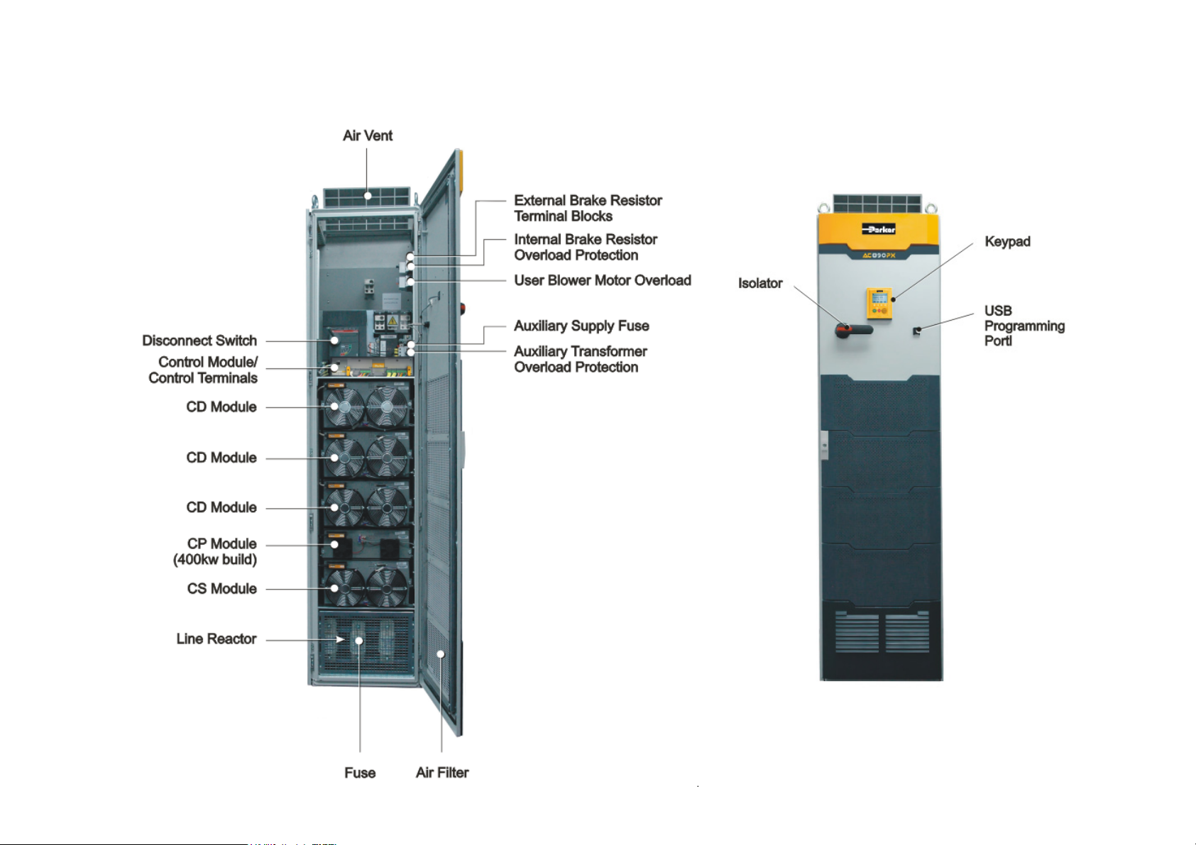
Component Identification
890PX (top wire entry)
AC890PX AC Drive
Page 17
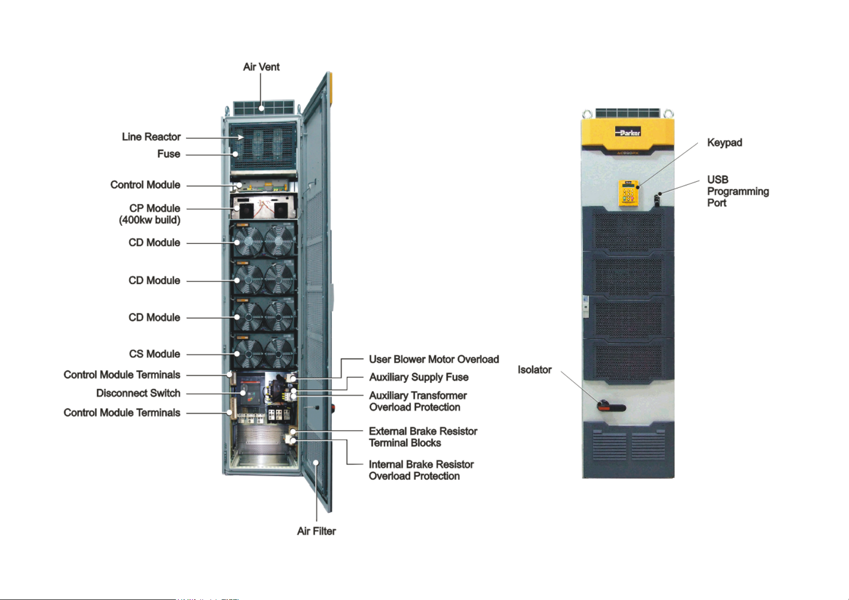
C h a p t e r 2 : P r o d u c t O v e r v i e w 2-5
AC890PX AC Drive
890PX (bottom wire entry)
Page 18
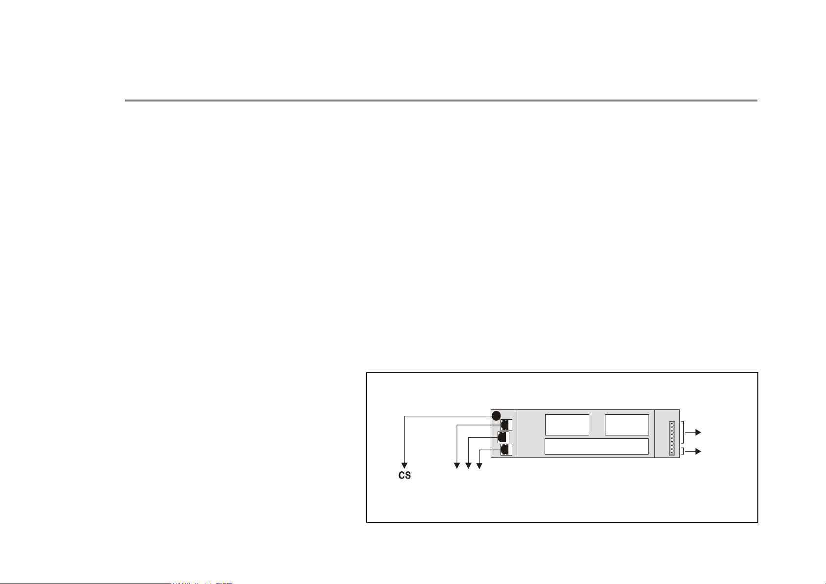
2-6 C h a p t e r 2 : P r o d u c t O v e r v i e w
The Modules
Control Module
The Control Module provides control for the drive and communicates with the CS Module via an RS485 connection. The
module is fitted with a control board that is common to all 890 drives.
Control Board Access
You can access the control board from the front of the Control Module.
• It contains a Processor that provides a range of analog and digital inputs/outputs, together with their reference supplies.
• The control board is fitted with a mini USB port for connection to a PC: terminal X10. This connection is also made
available on the front of the drive as a full size USB-A terminal. This is for use when the drive is powered by the 3-phase
supply which requires the enclosure door to be shut. Use the Parker SSD Drives’ DSE 890 (Drive Systems Explorer)
Configuration Tool to graphically program and configure the drive.
• The drive can also be configured by powering just the Control Module using an external 24V dc supply with the 3-phase
supply not connected. Refer to Chapter 3: "2.2 Control Connections" - USER 24V DC INPUTS table for more details.
to
CS Module
UWV
to
CD Modules
Option
A
Control Board
Control Module
Option
B
Control
Relays
Motor
Thermistor
AC890PX AC Drive
Page 19
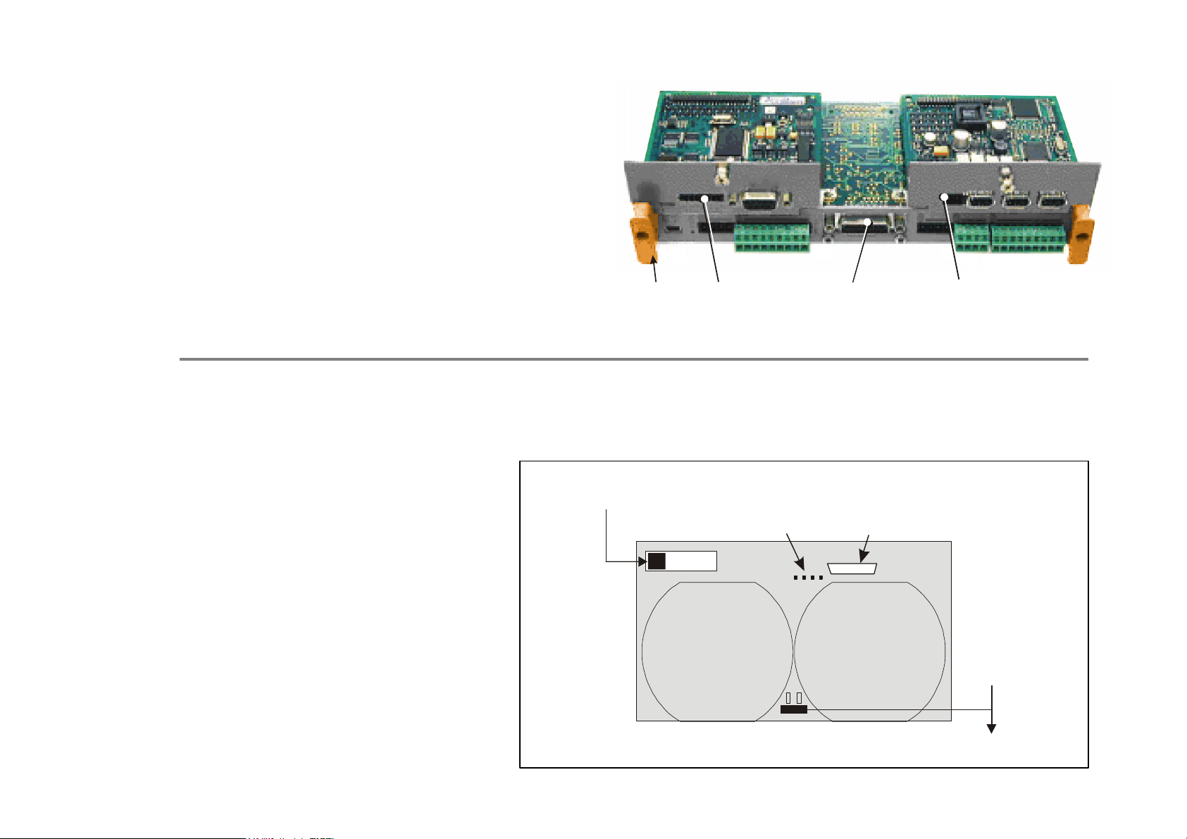
Option Cards
A
The AC890PX can be fitted with a range of Option
Cards. These are plugged into the control board slots
for OPTION A, OPTION B AND OPTION F:
• Feedback Board : Resolver type, Encoder type
• Fieldbus Comms - all major protocols
Refer to Appendix A : "Options".
C h a p t e r 2 : P r o d u c t O v e r v i e w 2-7
CD Module
This single phase output module provides one phase of the complete drive. The module is inter-changeable, allowing it to be
fitted to the drive in any of three CD Module positions. The module requires no user set-up.
A 10-way connector provides control
information from the Control Module.
The module has local over-voltage,
over-current and over-temperature
protection. The fan control is local to
each CD Module, thus each module's
fans may be operating at different
speeds at any given time.
Four diagnostic leds provide troubleshooting information for the module.
The 25-way diagnostic connector is for
use by Parker SSD Drives' engineers.
Control
Board
from
Control Module
UVW
OPTION A
Diagnostic
LEDs
OPTION F
Diagnostic
Connector
OPTION B
uxiliary
Supply
CD Module
AC890PX AC Drive
Page 20
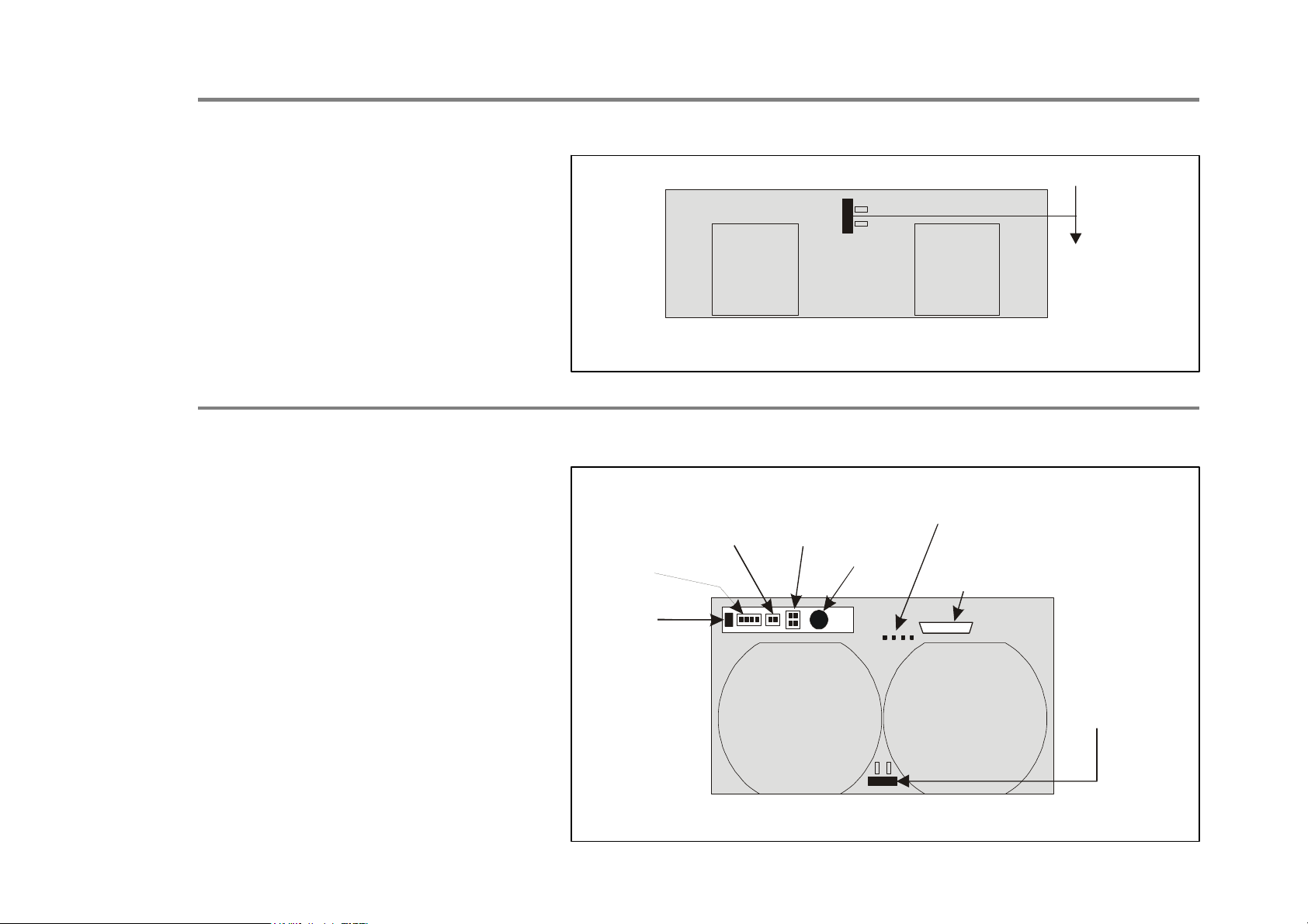
2-8 C h a p t e r 2 : P r o d u c t O v e r v i e w
A
A
CP Module
The CP Module is only fitted to 400kW
drives.
The capacitors in the CP Module
provide the required bus capacitance.
CS Module
This 3-phase input rectifier module
contains a half-controlled diode/
thyristor bridge. It supplies DC to the
three CD Modules and requires no user
set-up.
A connector provides control
information from the Control Module.
The module has local over-voltage,
over-current and over-temperature
protection. The fan control is local to
the CS Module.
RS485
P3 Port
CP Module
Thermistor
Feedback
CP Module
External
Brake
Option
From
Control
Module
uxiliary
Supply
Diagnostic
LEDs
Diagnostic
Connector
Four diagnostic leds provide troubleshooting information for the module.
The 25-way diagnostic connector is for
use by Parker SSD Drives' engineers.
uxiliary
Supply
CS Module
AC890PX AC Drive
Page 21
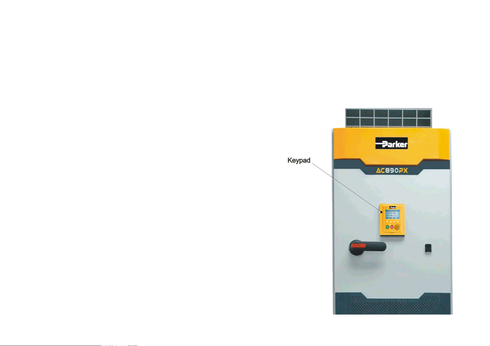
The Keypad
The AC890PX AC Drive is fitted with a removable Keypad.
The Keypad is used to control the drive locally. For example, you can start and stop the motor and check on diagnostic
information. It provides plain language programming and can also upload, store and download parameters.
The Keypad fits to the front of the AC890PX.
You can also remote-mount the Keypad up to 3 metres away.
For remote-mounting, you’ll need the correct Remote Mounting
Kit. Refer to Chapter 6: "The Keypad".
C h a p t e r 2 : P r o d u c t O v e r v i e w 2-9
AC890PX AC Drive
Page 22

2-10 C h a p t e r 2 : P r o d u c t O v e r v i e w
AC890PX AC Drive
Page 23

C h a p t e r 3 : I n s t a l l i n g t h e D r i v e 3-1
C h a p t e r
I n s t a l l i n g t h e D r i v e
This chapter describes the mechanical and electrical installation of the AC890PX AC
Drive. It discusses configuring your system, and how to turn the motor for the first time.
Follow the steps for a successful installation.
3
AC890PX AC Drive
Page 24

3-2 C h a p t e r 3 : I n s t a l l i n g t h e D r i v e
Step 1: Mechanical Installation
IMPORTANT
NOTE Refer to Appendix C for information about EMC compliance.
1.1: Mounting the Drive
NOTE The bottom wire entry version of the drive will sit on a plinth (allowing the cables to be fed through the bottom of the
The AC890PX is classed as a "Complete Drive Module". DO NOT install external equipment into the AC890PX
enclosure.
Main Points
♦ This is a standalone unit.
♦ Provide adequate ventilation.
♦ Avoid excessive vibration.
Prepare a clear, flat surface to receive the drive before attempting to move it.
It may be lifted by forklift either in it its final upright position, or lying on its back.
The drives are supplied with 4 lifting eyes fitted to the top of the drive enclosure for handling using a hoist.
During operation it must stand vertically on a solid, flat, horizontal, normally cool, non-flammable surface. With any tall unit
such as the AC890PX drive, it is advisable to secure the top to prevent it tipping over.
drive). In this case, also secure the drive to the plinth.
Drive Weights
132kW 600lbs (272kg)
200kW 600lbs (272kg)
315kW 732lbs (333kg)
400kW 790lbs (360kg)
AC890PX AC Drive
Page 25
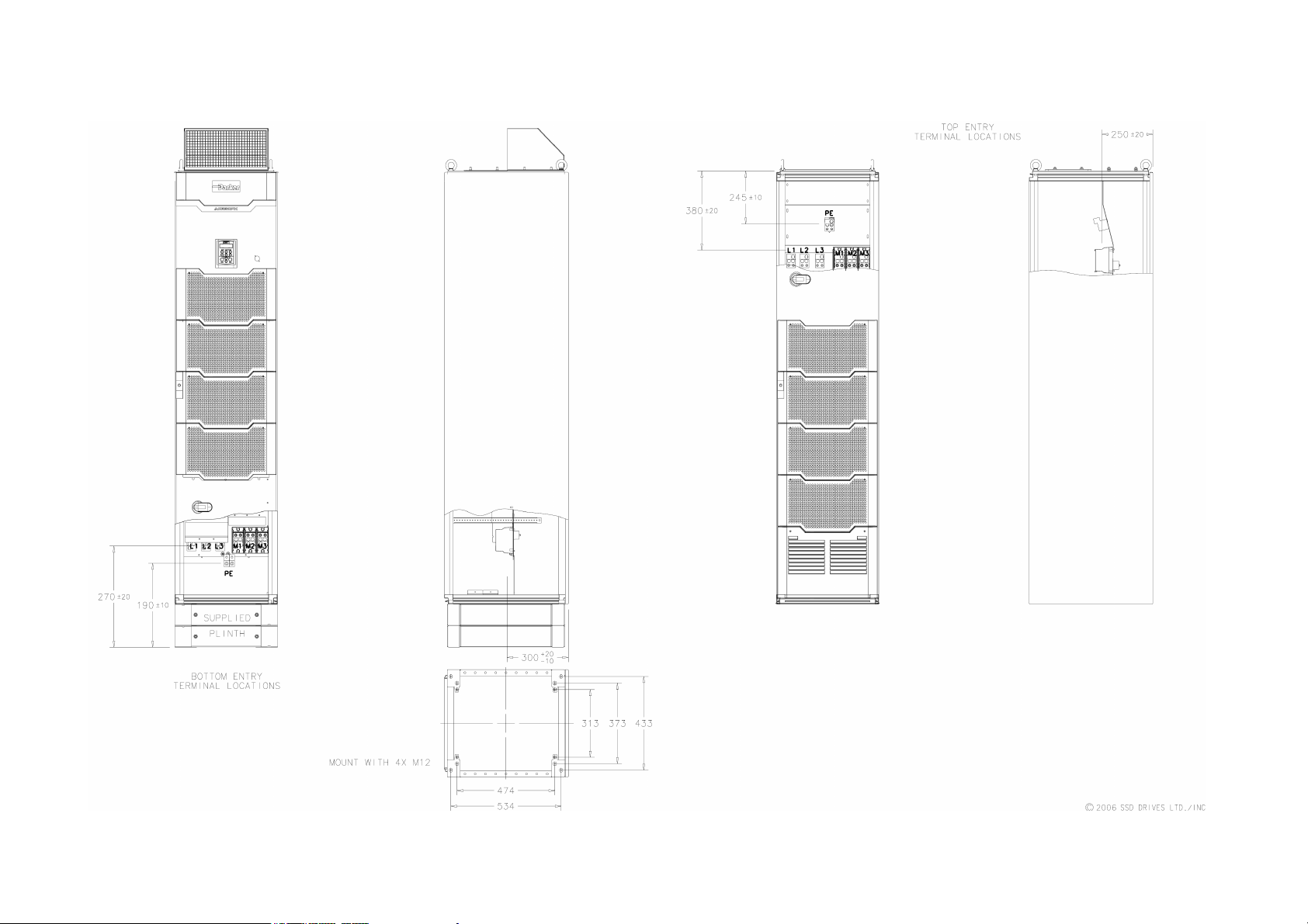
Installation Drawings
C h a p t e r 3 : I n s t a l l i n g t h e D r i v e 3-3
AC890PX AC Drive
Outline Drawing of AC890PX, 132kW - 400kW - HC471581 page 1 of 2
Page 26
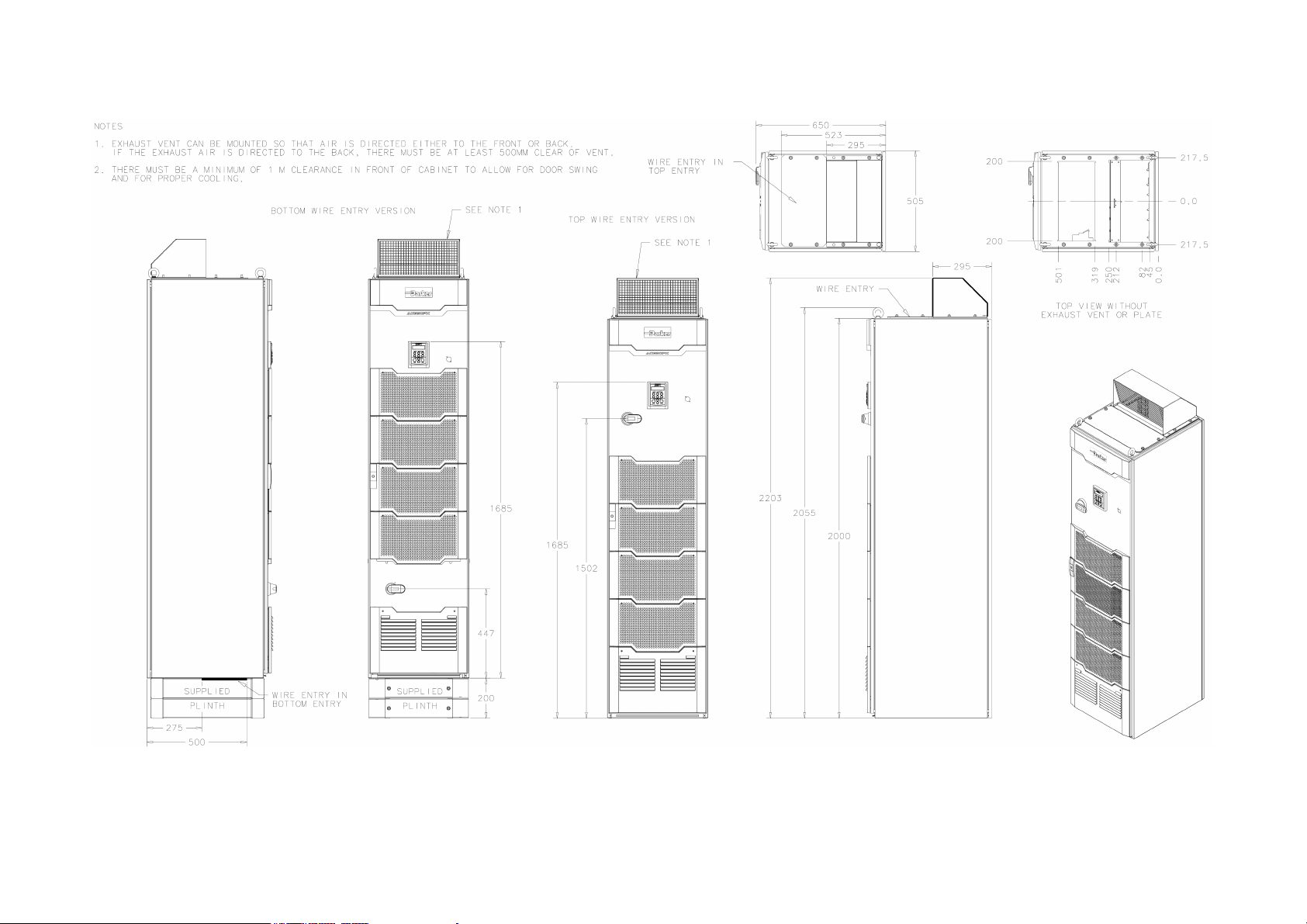
3-4 C h a p t e r 3 : I n s t a l l i n g t h e D r i v e
Outline Drawing of AC890PX, 132kW - 400kW - HC471581 page 2 of 2
AC890PX AC Drive
Page 27

Operating Conditions
Drive Enclosure Information
C h a p t e r 3 : I n s t a l l i n g t h e D r i v e 3-5
Operating Temperature
Enclosure Rating UL (c-UL) Enclosed Type 1 (North America/Canada) - as defined by UL50
Enclosure Rating
0°C to 40°C (32°F to 104°F), derate up to a maximum of 50°C
Derate linearly at 1% per degree centigrade for temperature exceeding the
maximum rating ambient for the drive.
CE - The enclosure meets the requirements of IP21 as defined by EN 60529
The enclosure provides the following attenuation to radiated emissions:
Attenuation to RF in
EMC Enclosure Standard
EN61800-3 Category C3 NONE
EN61800-3 Category C2 Restricted Distribution
EN61000-6-3
EN61800-3 Category C1 Unrestricted Distribution
EN61000-6-4
Humidity
Atmosphere Non flammable, non corrosive and dust free
Maximum 85% relative humidity at 40°C (104°F) non-condensing
spectrum 30-1000MHz
10db
20db
Altitude If greater than 1000m above sea level, derate by 1% per 100m to a
maximum of 5000m
Safety:
Overvoltage Category
Pollution Degree Pollution Degree II (non-conductive pollution, except for temporary
AC890PX AC Drive
Overvoltage Category III
condensation)
Page 28
3-6 C h a p t e r 3 : I n s t a l l i n g t h e D r i v e
Vibration The product has been tested to the following specification:
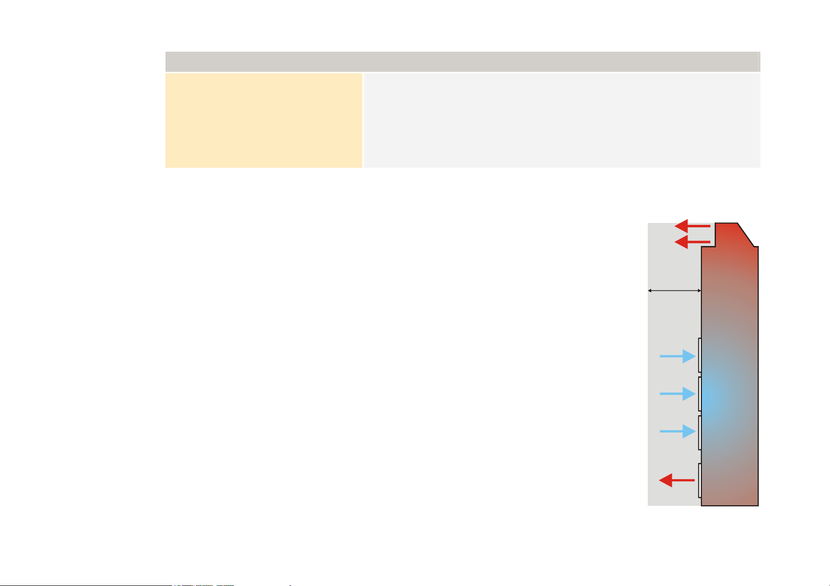
Air Flow and Ventilation Requirements
The drive uses very large airflows and has been designed with specific airflow patterns
within the enclosure. Mount the drive to allow for a free flow of air through the air
filters on the front of the enclosure, and out through the top and bottom of the drive.
The mounting surface for the drive must be normally cool.
Drive Enclosure Information
Test Fc of EN60068-2-6
10Hz<=f<=57Hz sinusoidal 0.075mm amplitude
57Hz<=f<=150Hz sinusoidal 1g
10 sweep cycles per axis on each of three mutually perpendicular axis
2/3
OUTLET AIR
Substantial heat is dissipated (refer to Appendix E: “Technical Specifications” –
Electrical Ratings, for Total Power Loss) and therefore sufficient volume for exhaust
venting is required to keep the drive from raising the operating temperature beyond
that specified in the Environmental Specification.
Maintain a 100cm air clearance at the front (air vent and filters) and top of the drive
(air vent). It is possible to turn the top air vent through 180°, in which case air
clearance must be maintained at the rear of the drive also. Air clearances are not
required on the remaining surfaces of the drive.
Ensure that heat generated by other adjacent equipment is not transmitted to the drive.
Be aware that other equipment may have its own clearance requirements.
100cm
minimum
air
clearance
INLET AIR
1/3
OUTLET AIR
1000 CFM 1700 CMH
Total flow at full load
AC890PX AC Drive
Page 29
C h a p t e r 3 : I n s t a l l i n g t h e D r i v e 3-7
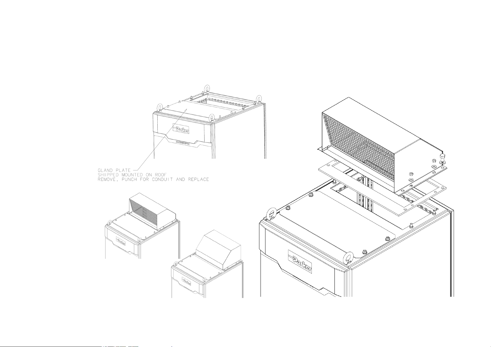
Fitting the Vent Hood
Remove the rear lifting eyes from the top of the drive. Place the gasket (provided) over the hole where the vent will fit. Install
the vent hood, facing either forwards or backwards. Secure it using 2 x M12 bolts and 4 x M8 nuts. Do not overtighten. The
gasket should be compressed evenly and the vent hood must not be distorted.
AC890PX AC Drive
Page 30
3-8 C h a p t e r 3 : I n s t a l l i n g t h e D r i v e
Step 2: Electrical Installation
NOTE Refer to Chapter 9: "Routine Maintenance and Repair" for details of fitting a module into the drive.
IMPORTANT
NOTE An external motor overload protective device must be provided by the installer where the motor has a full-load
Please read the Safety Information on page Cont.3 & 4 before proceeding.
WARNING
During commissioning, remove the fuses (or trip the circuit breaker) on your 3-phase supply.
Make sure the power is OFF, and that it cannot be switched on accidentally whilst you are working.
Allow at least 10 minutes for the drive's capacitors to discharge to safe voltage levels (<50V).
Ampere rating of less than 50% of the drive output rating; or when the MOTOR STALLED trip is TRUE (TRIPS
STATUS::DISABLE TRIPS>>MOTOR STALLED); or when the STALL TIME parameter is increased above 480
seconds.
Cable Specification
Ensure your wiring is rated for the highest system voltage.
Cable Entry
There are two drive versions : top wire entry and bottom wire entry. Refer to
Chapter 2: "Product Overview" - Component Identification to identify your drive
type.
Provide glands for cabling. These should be of at least the same IP rating as the
drive in order to preserve the overall rating for the drive. The removable plates
with gaskets in the top/bottom of the drive should be punched/drilled to match the
glands in use.
Maintain maximum separation between power cables and control wiring. Control
wiring should be run in trunking down the left hand side front edge (when veiwed
from the front of the drive).
Rear of Drive
Power Cabling
CONTROL MODULE
Control Cabling
NOTE Refer to Appendix C: “Certification for the Drive” for EMC installation
options.
Horizontal cross-section through Drive
AC890PX AC Drive
Page 31
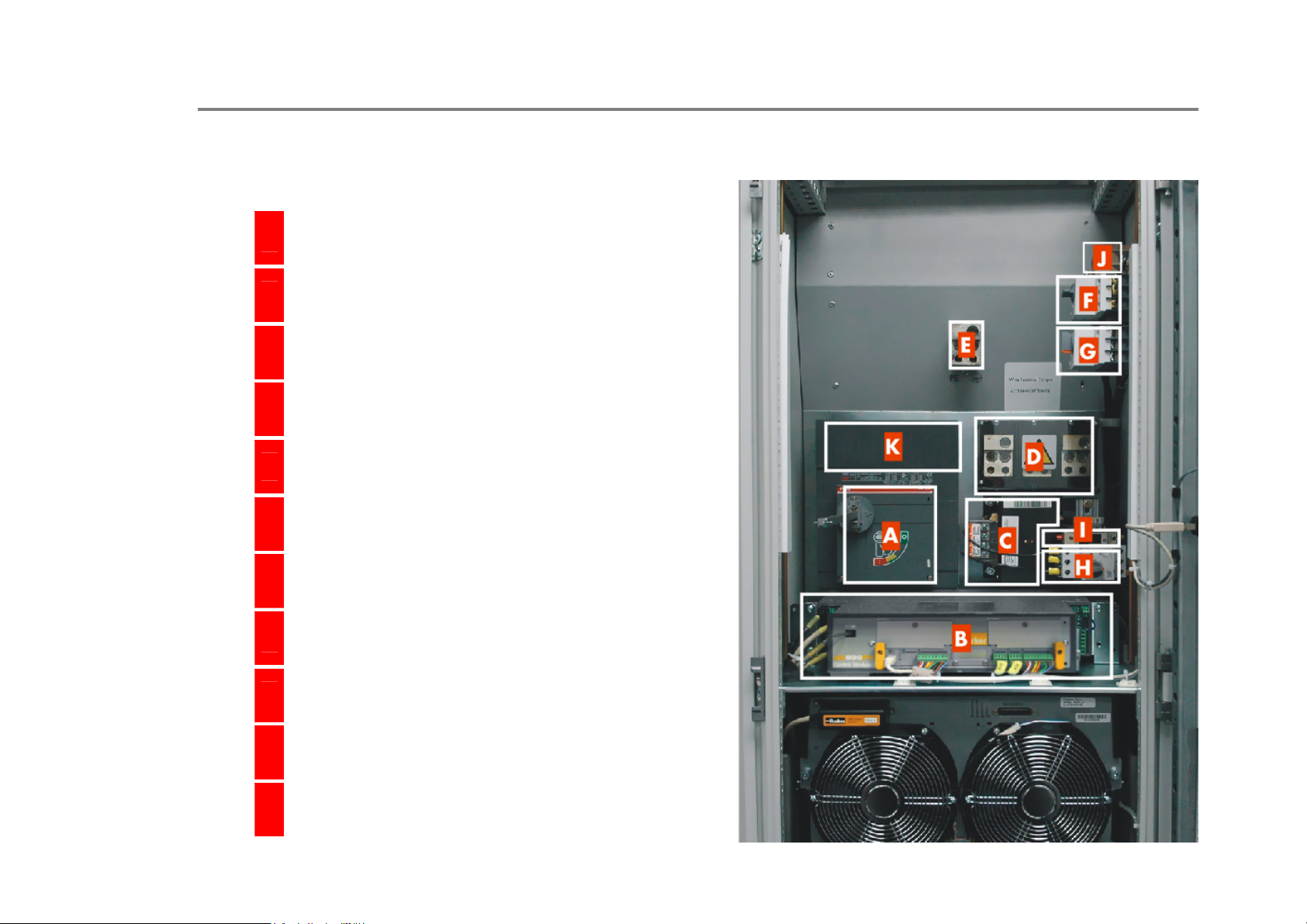
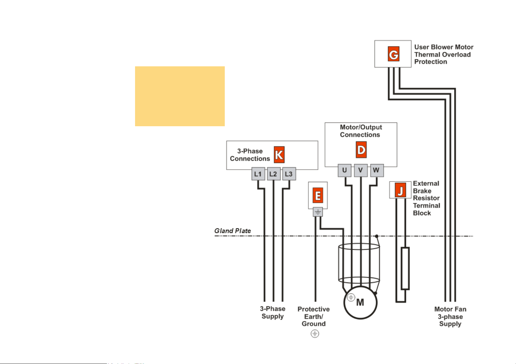
2.1: Power Connections
Top Wire Entry
Isolator
A
Control Module/Control Terminals
B
Auxiliary Transformer
C
Set the transformer taps - see page 3-16.
Motor/Output Connections
D
Protective Earth/Ground
E
C h a p t e r 3 : I n s t a l l i n g t h e D r i v e 3-9
AC890PX AC Drive
Internal Brake Resistor Thermal Overload Protection
F
User Blower Motor Thermal Overload Protection
G
Auxiliary Supply Protection - Circuit Breaker
H
(primary)
Auxiliary Supply Protection - Semiconductor Fuse
I
(secondary)
External Brake Resistor Terminal Block
J
3-Phase Connections
K
Page 32
3-10 C h a p t e r 3 : I n s t a l l i n g t h e D r i v e
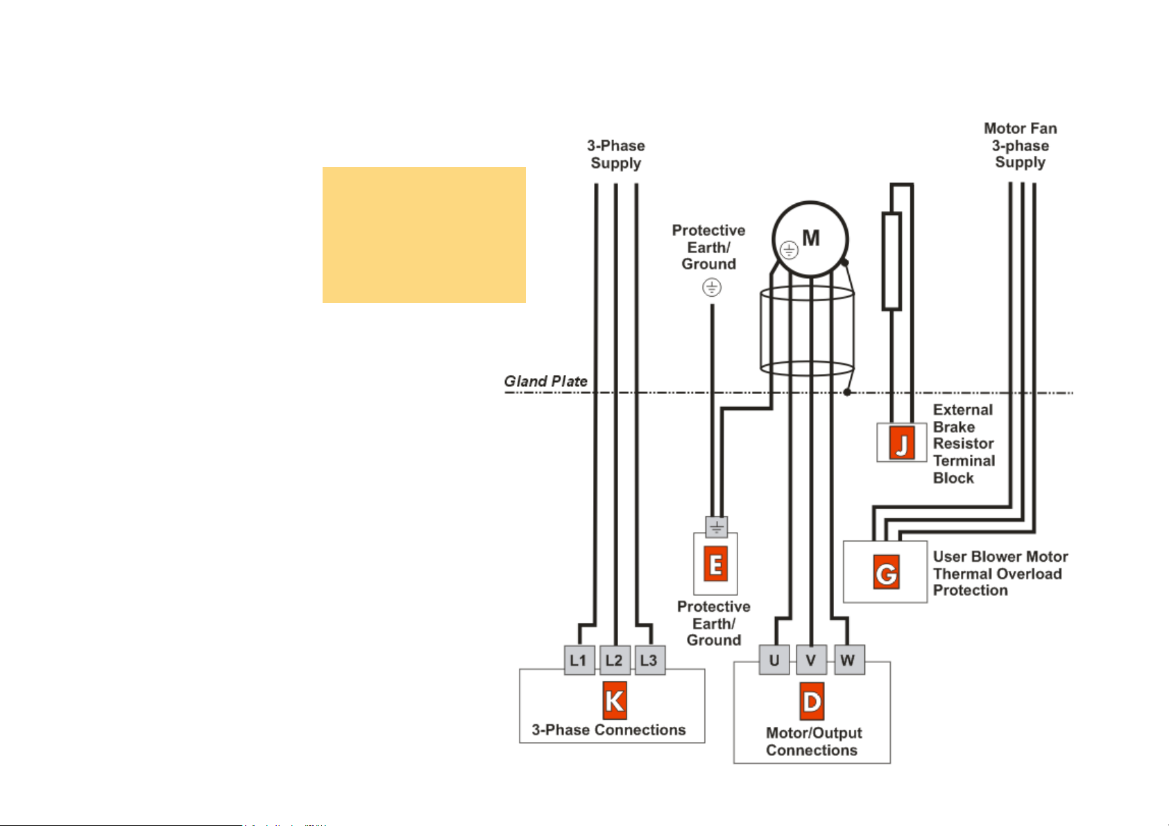
Top Wire Entry
Refer to Appendix C for
UL wires sizes.
Customers in Europe
should refer to EN 60204-1
and local wiring
regulations.
AC890PX AC Drive
Page 33
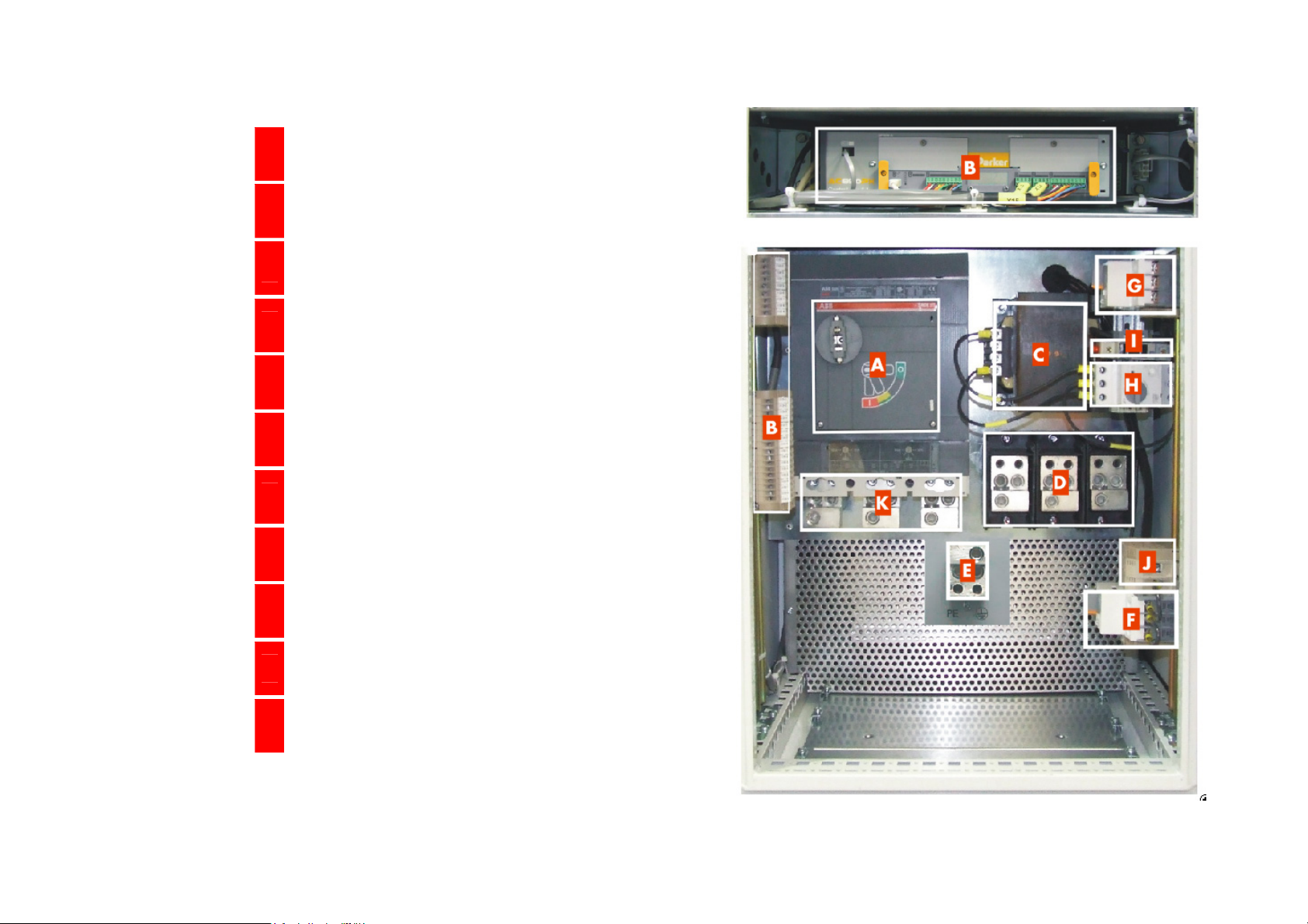
Bottom Wire Entry
Isolator
A
Control Module/Control Terminals
B
Auxiliary Transformer
C
Set the transformer taps - see page 3-16.
Motor/Output Connections
D
Protective Earth/Ground
E
Internal Brake Resistor Thermal Overload Protection
F
User Blower Motor Thermal Overload Protection
G
C h a p t e r 3 : I n s t a l l i n g t h e D r i v e 3-11
AC890PX AC Drive
Auxiliary Supply Protection - Circuit Breaker
H
(primary)
Auxiliary Supply Protection - Semiconductor Fuse
I
(secondary)
External Brake Resistor Terminal Block
J
3-Phase Connections
K
Page 34
3-12 C h a p t e r 3 : I n s t a l l i n g t h e D r i v e
Bottom Wire Entry
Refer to Appendix C for
UL wires sizes.
Customers in Europe
should refer to EN 60204-1
and local wiring
regulations.
AC890PX AC Drive
Page 35
C h a p t e r 3 : I n s t a l l i n g t h e D r i v e 3-13
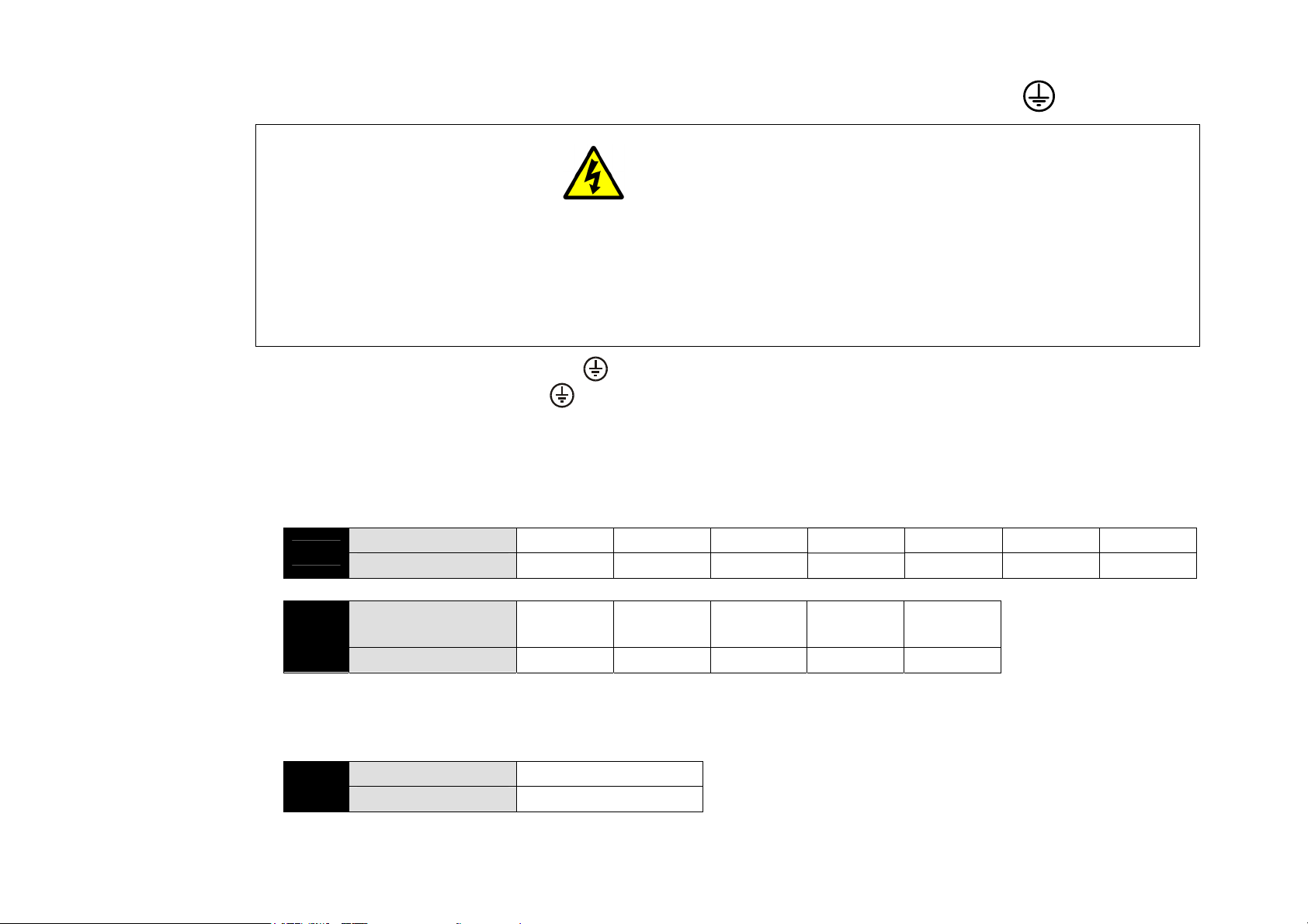
2.1.1 Protective Earth (PE)/Ground Terminals (E)
Permanent Earthing
The unit must be permanently earthed according to EN 61800-5. For permanent earthing, EN 61800-5 states that:
A cross-section conductor of at least 10mm² copper or 16mm2 aluminium is required.
Conductors must be sized in accordance with Local Wiring Regulations which always take precedence.
As a guide, refer to the Input Current for the drive given in the Electrical Ratings tables.
• Fix the Drive earth connection(s) to .
• Fix the earth from the Motor to .
2.1.2 3-Phase Connections (K)
• Remove the supply fuses from the drive and connect the 3-phase supply in any order.
• Branch fusing - not required.
AC890PX AC Drive
460V
575V
Drive Model 4/0215 4/0260 4/0300 4/0420 4/0480 4/0520 4/0580
Tightening Torques 31Nm 31Nm 31Nm 31Nm 43Nm 43Nm 43Nm
Drive Model
Tightening Torques 26Nm 26Nm 31Nm 31Nm 31Nm
6/1030
7/0130
6/0160
7/0160
6/0190
7/0190
2.1.4 Motor/Output Connections (D)
• Connect to the motor in any order.
460V
575V
Drive Model all models
Tightening Torques 42.5Nm
6/0280
7/0280
6/0340
7/0340
Page 36
3-14 C h a p t e r 3 : I n s t a l l i n g t h e D r i v e
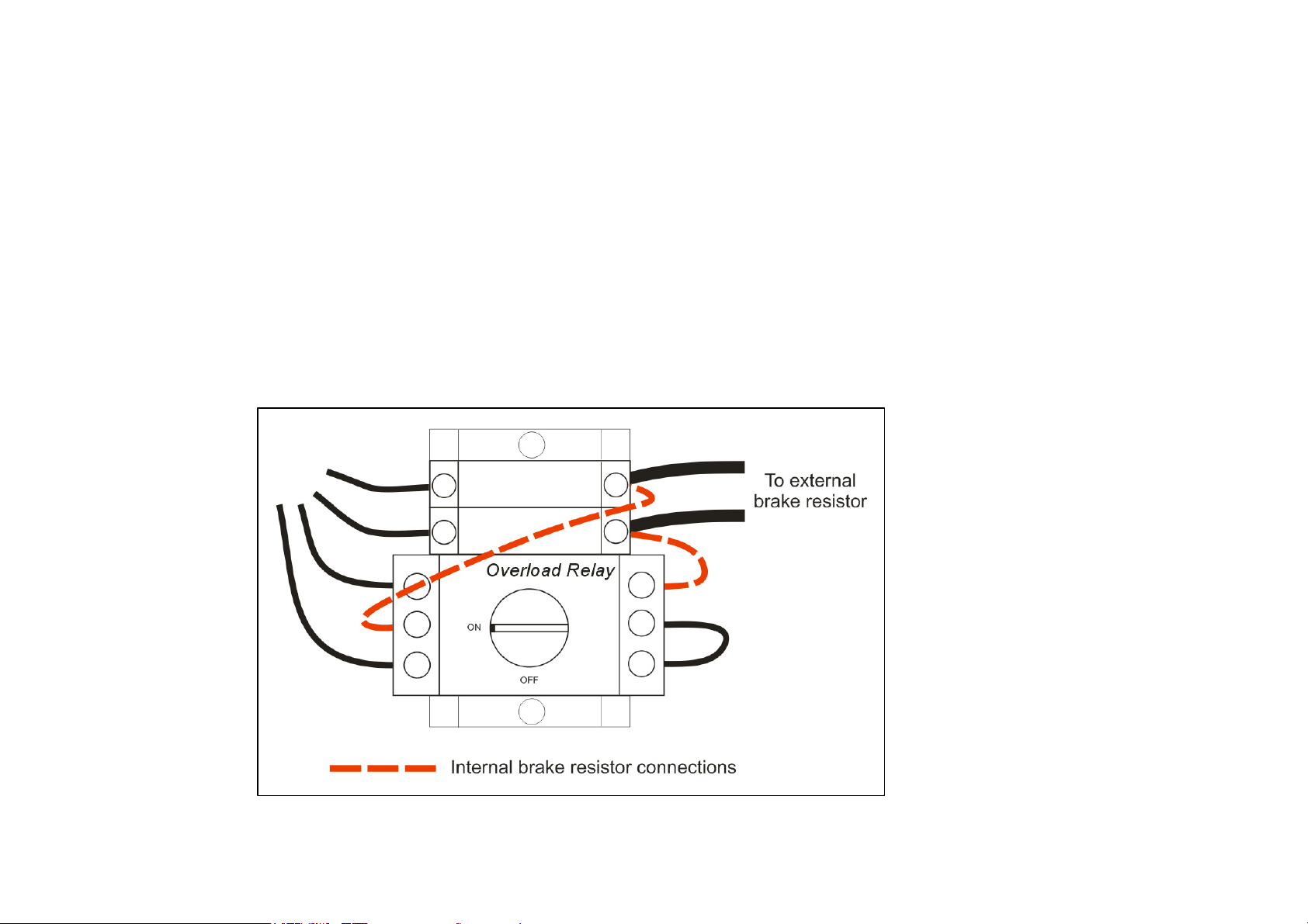
2.1.5 External Brake Resistor (J)
The AC890PX is fitted with an internal resistor. Removing the internal brake resistor connections will disconnect the internal
braking resistor allowing the connection of an external brake resistor.
NOTE It is possible to use both the internal and external brake resistors (wired as shown) but we recommend you contact
Parker SSD Drives for advice.
Refer to Chapter 4: "Associated Equipment" - External Braking Resistors for help with using and selecting external brake
resistors.
The overload relay protects the internal brake resistor. The switch will require resetting to "ON" if the drive trips on BRAKE
SWITCH (the keypad display).
There are similar trips to protect the external brake resistor. Refer to Chapter 8: "Trips and Fault Finding".
AC890PX AC Drive
Page 37
C h a p t e r 3 : I n s t a l l i n g t h e D r i v e 3-15
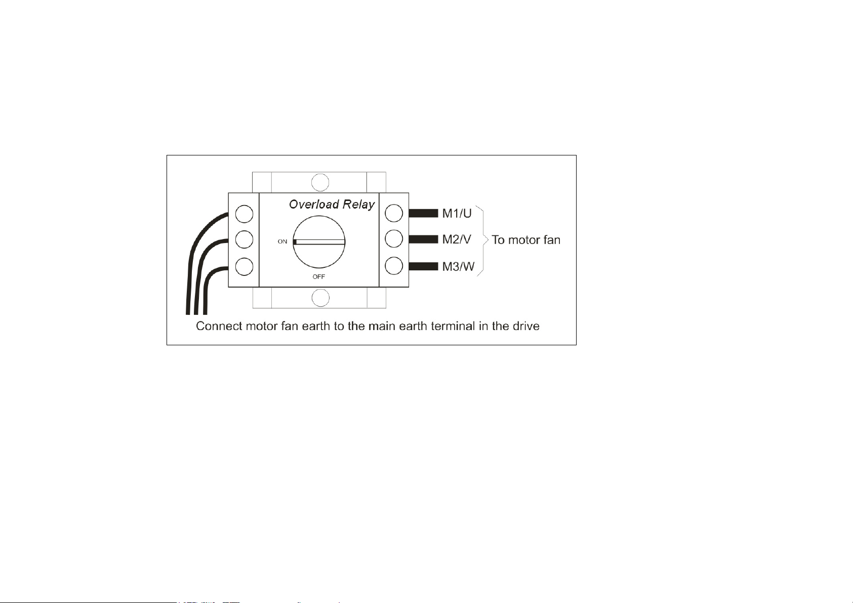
2.1.6 Blower Motor Thermal Overload Protection (G)
The drive provides a 3-phase supply for the motor fan.
The overload relay switches the power on/off. The switch, rated at 4-6A, is adjusted to trip if the motor fan draws more than
5A. In the event of a trip, the switch will require resetting to ON.
AC890PX AC Drive
Page 38
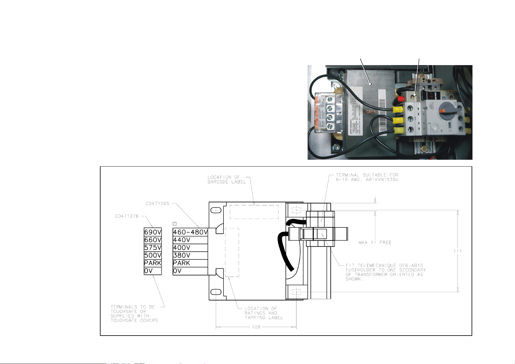
3-16 C h a p t e r 3 : I n s t a l l i n g t h e D r i v e
2.1.7 Auxiliary Transformer Taps (C)
The transformer is tapped for no connection, i.e. 0V - PARK when
it leaves the factory and the drive will not operate. Either a low
voltage or high voltage transformer option is fitted to the drive.
Match the auxiliary transformer tap to the drive's nominal supply
voltage. For example, connect the taps to 0V and 400V for a
nominal supply voltage of 400Vac.
The transformer supplies a constant 30Vac to the Control Module,
internal fans etc. It is protected by a 40A semi-conductor fuse
40A Semi-Conductor FuseAuxiliary Transformer
AC890PX AC Drive
Page 39
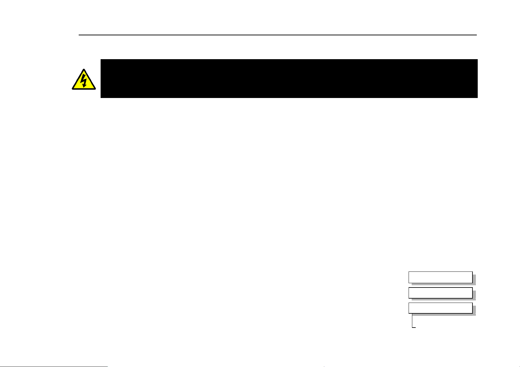
2.2: Control Connections
p
During commissioning, remove the fuses (or trip the circuit breaker) on your 3-phase supply.
Make sure the power is OFF, and that it cannot be switched on accidentally whilst you are working.
Allow at least 10 minutes for the drive's capacitors to discharge to safe voltage levels (<50V).
Main Points
♦ The control connections are made to the Control Module. (Where the drive is a bottom wire entry version, the control
terminals are brought out to a second set of terminal blocks in the bottom of the drive).
♦ The control terminals will accept a single wire of size 1.5mm2/16AWG. For two wires per terminal, use smaller gauge
wire such as 0.5mm2/22AWG.
♦ Use screened control cables to comply with EMC requirements. All screens must be terminated using the cable clamp on
the Control Module. (Where the drive is a bottom wire entry version, screens must be terminated close to the terminal
blocks in the bottom of the drive using DIN rail mounted screen clamps).
♦ The control board 0V at X14/04 must be connected to protective (clean) earth outside of the product to meet EMC and
safety requirements. Provide a separate clean earth connection to this terminal from outside of the drive.
C h a p t e r 3 : I n s t a l l i n g t h e D r i v e 3-17
WARNING
Motor Thermistor
♦ If the motor does not have a protective device (thermistor), it is important to link these terminals (supplied linked by
default), or set SETUP::TRIPS::I/O TRIPS::INVERT THERMIST to True. The drive needs the thermistor inputs
connected for it to run.
♦ Connect a motor thermistor PTC `Type A’, or motor thermal switch. The drive will trip when
the thermistor resistance exceeds 4kΩ maximum (IEC 34-11 Part 2), or thermal switch opens.
♦ Connect the motor's thermistor in any order. Run the wiring in front of the Control Module,
securing it to other control wiring. Secure the wiring to the left hand side of the drive, tucking
it away behind trunking where possible.
♦ The drive uses the following resistance thresholds:
Ω
Rising temperature trip resistance: 1650 to 4000
Falling temperature trip reset resistance: 750 to 1650Ω
AC890PX AC Drive
MMI Menu Ma
SETUP
1
TRIPS
2
I/O TRIPS
3
INVERT THERMIST
Page 40
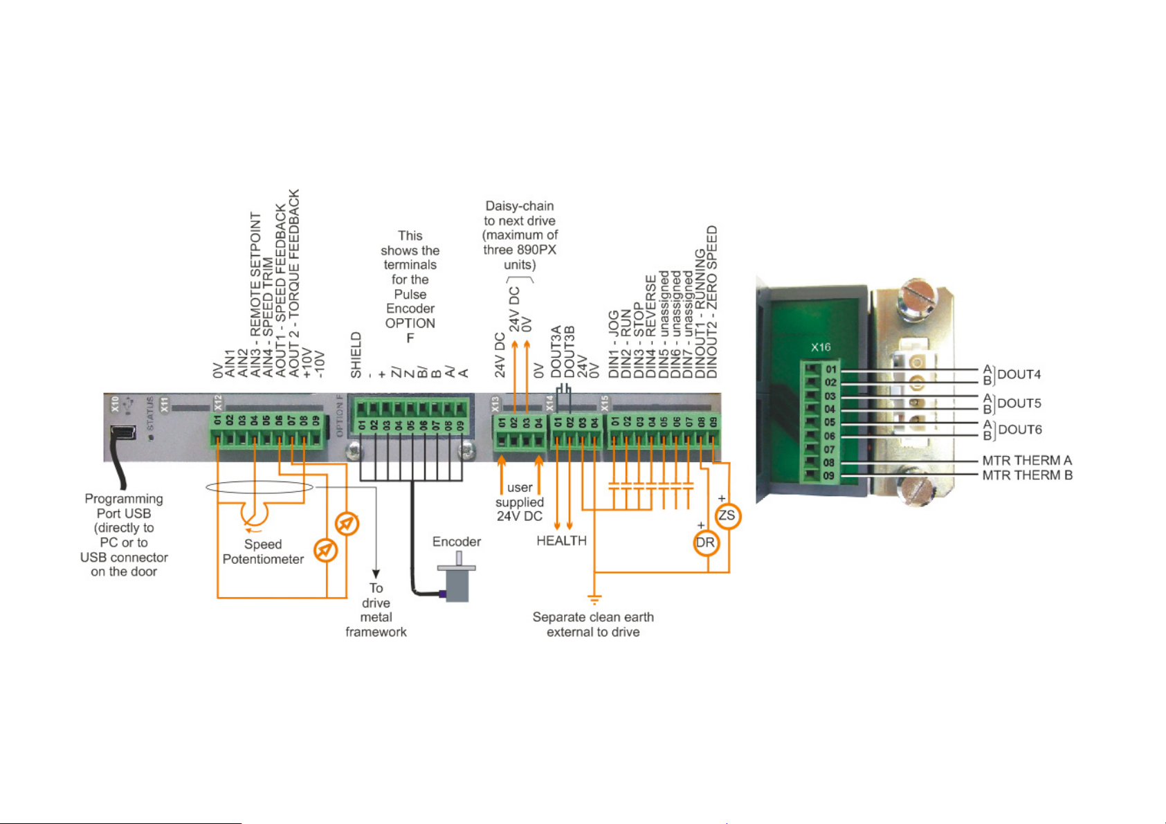
3-18 C h a p t e r 3 : I n s t a l l i n g t h e D r i v e
Full Connection Diagram
Connect to the control terminals. Cables must be secured together with a cable tie as close to the terminals as possible.
AC890PX AC Drive
Page 41
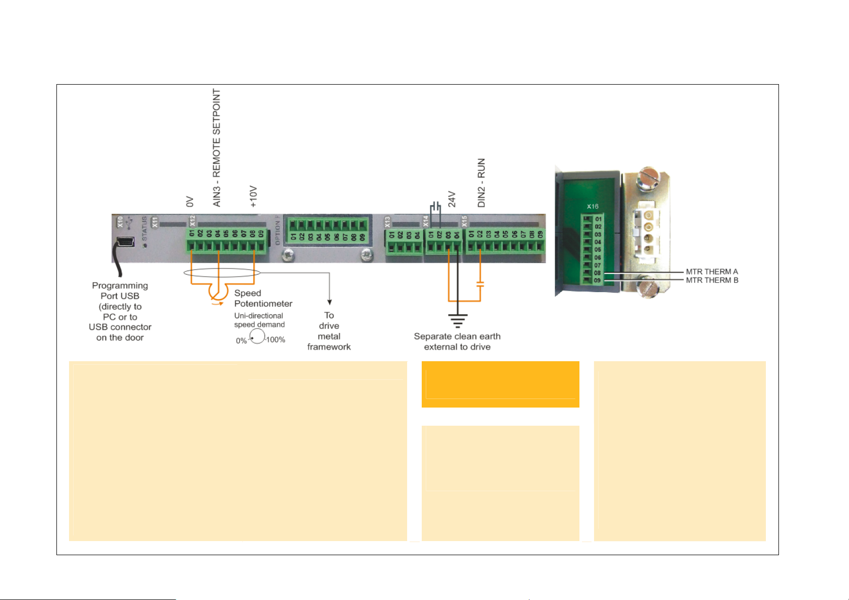
Minimum Connection Diagram
C h a p t e r 3 : I n s t a l l i n g t h e D r i v e 3-19
Speed Reference
• Connect a 10kΩ potentiometer
at terminal X12:
X12/01 : Low (CCW)
X12/04 : Wiper
X12/08 : High (CW)
• Connect the shield to
earth/ground on the metal
framework inside the
enclosure.
AC890PX AC Drive
OR
• External 2-wire speed
reference between:
X12/01 : negative
X12/04 : positive
• Connect the shield to
earth/ground on the metal
framework inside the
enclosure.
• Connect X14/04 to a
clean, external earth.
Sequencing
• RUN (maintained contact):
X14/03 : 24V
X15/02 : RUN
Motor Thermistor
• Recommended : Connect to a
motor fitted with an internal
motor thermistor (connections
have no polarity)
OR
♦ Jumper the terminals
OR
♦ Disable the thermistor trip
function by setting INVERT
THERMIST to be TRUE.
Page 42
3-20 C h a p t e r 3 : I n s t a l l i n g t h e D r i v e
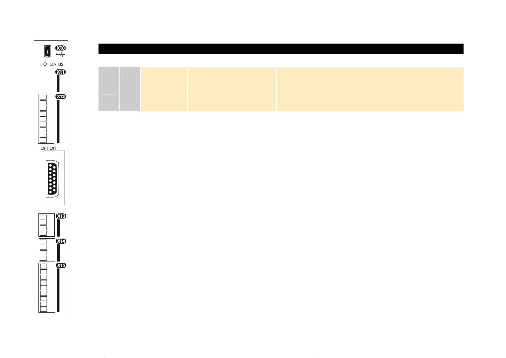
Mini USB Port
X10
Name Range Description
This Mini USB port provides a serial communications link to
a host computer running the DSE 890 Configuration Tool.
USB
It is made available on the front of the drive, for use when the
drive is powered by the 3-phase supply. Use an approved USB
lead.
AC890PX AC Drive
Page 43
C h a p t e r 3 : I n s t a l l i n g t h e D r i v e 3-21
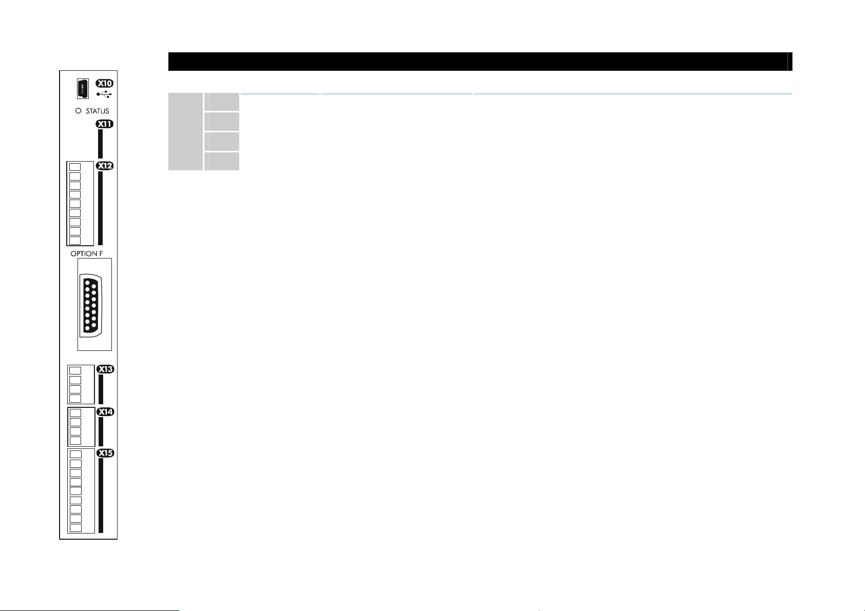
FUTURE USE
X11
Terminal X11 is for future use.
Name Range Description
01
02
03
04
AC890PX AC Drive
Page 44
3-22 C h a p t e r 3 : I n s t a l l i n g t h e D r i v e
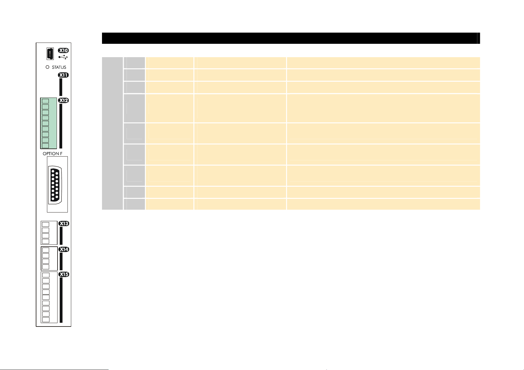
ANALOG I/O
X12
NOTE AIN1 and AIN2 are fitted with a link to ensure no noise pick-up when not in use. These terminals can be used together
as a differential ±10V input (which we call AIN5), but AIN1 and AIN2 must remain within ±10V relative to 0V. AIN5
has a direct input into the Speed Loop providing a fast speed or torque demand for servos.
Name Range Description
0V 0V reference for analog I/O
01
AIN1
02
AIN2
03
AIN3
04
AIN4
05
AOUT1
06
AOUT2
07
+10V REF +10V (output) 10V reference for analog i/o. Load 10mA maximum
08
–10V REF -10V (output) 10V reference for analog i/o. Load 10mA maximum
09
0-10V, ±10V
0-10V, ±10V
±10V, 0-10V,
0-20mA, 4-20mA
±10V, 0-10V,
0-20mA, 4-20mA
±10V
(10V = 100% speed)
±10V
(10V = 200% torque)
Analog Input 1 (default = diff I/P +)
Analog Input 2 (default = diff I/P -)
Analog Input 3 (default = remote set point I/P)
-10V = 100.00% reverse, +10V = 100.00% forward (%
maximum speed)
Analog Input 4 (default = speed trim I/P)
Analog Output 1 (default = speed feedback O/P)
Analog Output 2 (default = torque feedback O/P)
All analog inputs/outputs are configurable using the DSE 890 (Drive System Explorer) Configuration Tool supplied on disk.
The table above shows the factory defaults. These analog connections require ±10V DC which is supplied at terminal X12/08
and X12/09 respectively. For further information refer to the DSE 890 Configuration Tool.
AC890PX AC Drive
Page 45
C h a p t e r 3 : I n s t a l l i n g t h e D r i v e 3-23
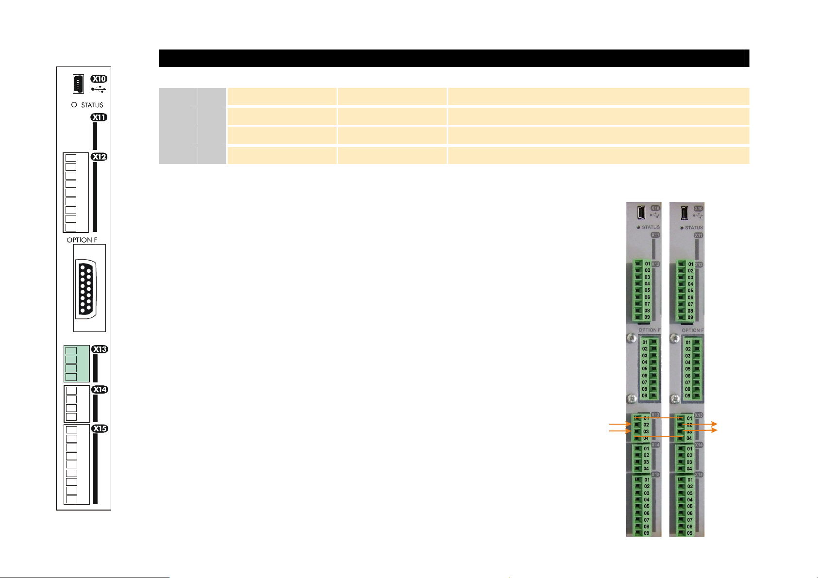
USER 24V DC INPUTS
Name Range Description
24V INPUT 24V DC User +24V (2A per unit)
01
24V INPUT 24V DC User +24V (2A per unit)
02
X13
0V INPUT 0V 0V (24V) input
03
0V INPUT 0V 0V (24V) input
04
NOTE These connections are not necessary for normal operation of the drive.
Supply an external 0V and +24V DC (±10%) control supply to this terminal to
configure and commission the drive without the 3-phase supply present. The drive
will not turn a motor. Each AC890PX can draw 2A, so for example: 3 units = 6A.
You can connect up to four AC890PX units using these terminals by daisy-chaining
the 24V supply (8A maximum). If you have more than four AC890PXs, wire each
drive individually from the 24V source.
Connection is not required when the 3-phase supply is present, but the connection
can be safely left connected.
The units are protected against reversal of this 24V DC supply.
1. Apply the 24V DC.
890PX
Drives
AC890PX AC Drive
2. Check that all keypads are active.
Because the unit is powering up without the 3-phase connection, the keypad will
display "TRIPPED UNDERVOLTAGE", a trip indicating that the supply is
missing. Press the ESC key whenever this message appears.
If the unit is not powering-up with 24V DC: check your supply; check your
connections at X13; check the keypad is fitted correctly. If you are still
experiencing problems, please contact Parker SSD Drives.
24V DC
24V DC
Page 46
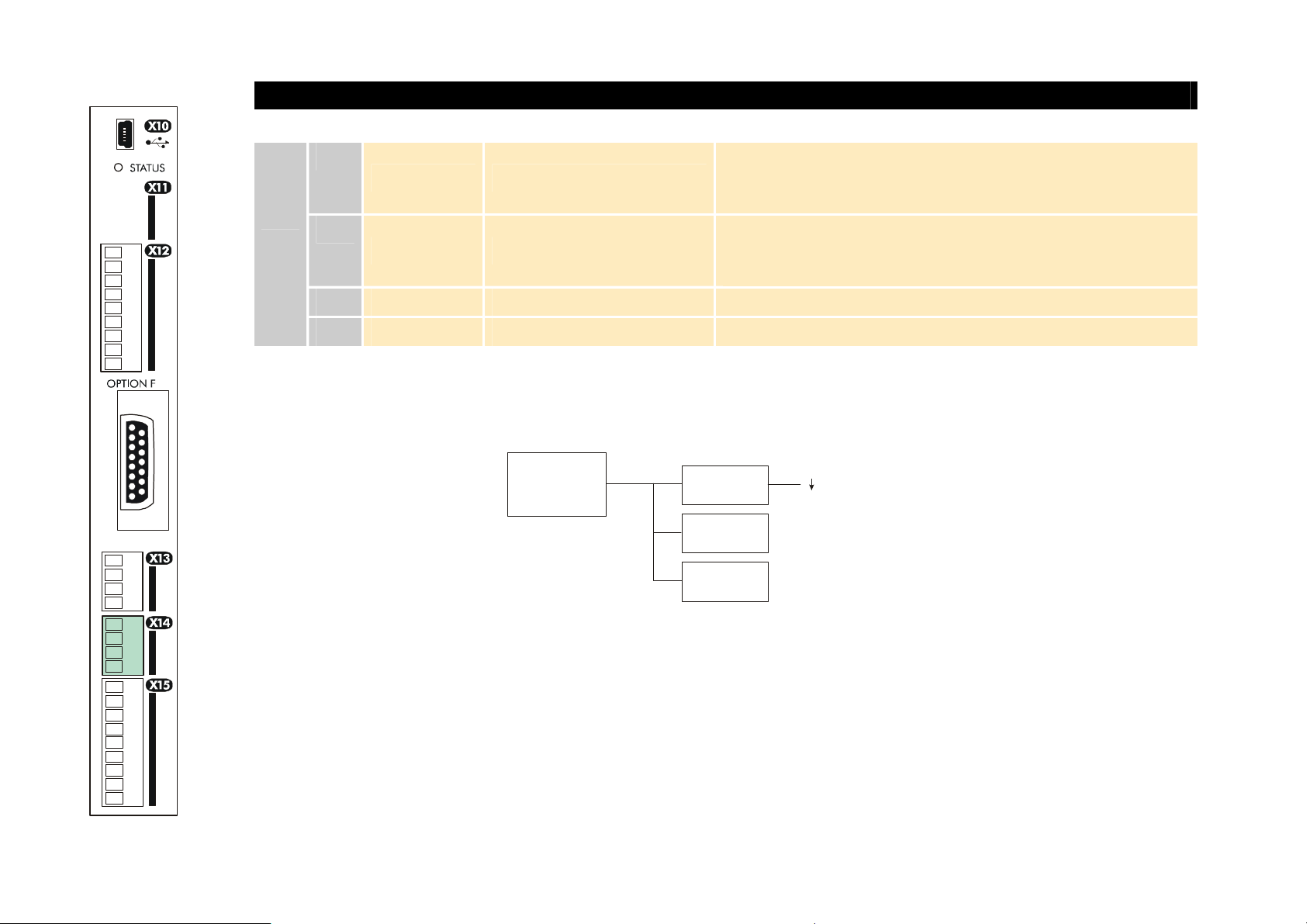
3-24 C h a p t e r 3 : I n s t a l l i n g t h e D r i v e
RELAY CONTACTS
X14
NOTE The maximum permissible sum of currents from X14/03, X15/08, X15/09 is 150mA. An Alert message will be
displayed if exceeded.
Name Range Description
01
DOUT3A 0-24V DC
02
DOUT3B 0-24V DC
USER 24V 0-24V DC 24V DC Output, 150mA maximum load
03
0V 0-24V DC 0V reference for USER 24V output
04
SUPPLY
150mA
Relay Output: normally-open, volt-free, 24V DC 1A resistive
load or use down to 1mA, 12V levels (DOUT3 closed =
HEALTH)
Relay Output: normally-open, volt-free, 24V DC 1A resistive
load or use down to 1mA, 12V levels (DOUT3 closed =
HEALTH)
X15/01
X14/03
(7mA each)
X15/07
X15/08
X15/09
AC890PX AC Drive
Page 47
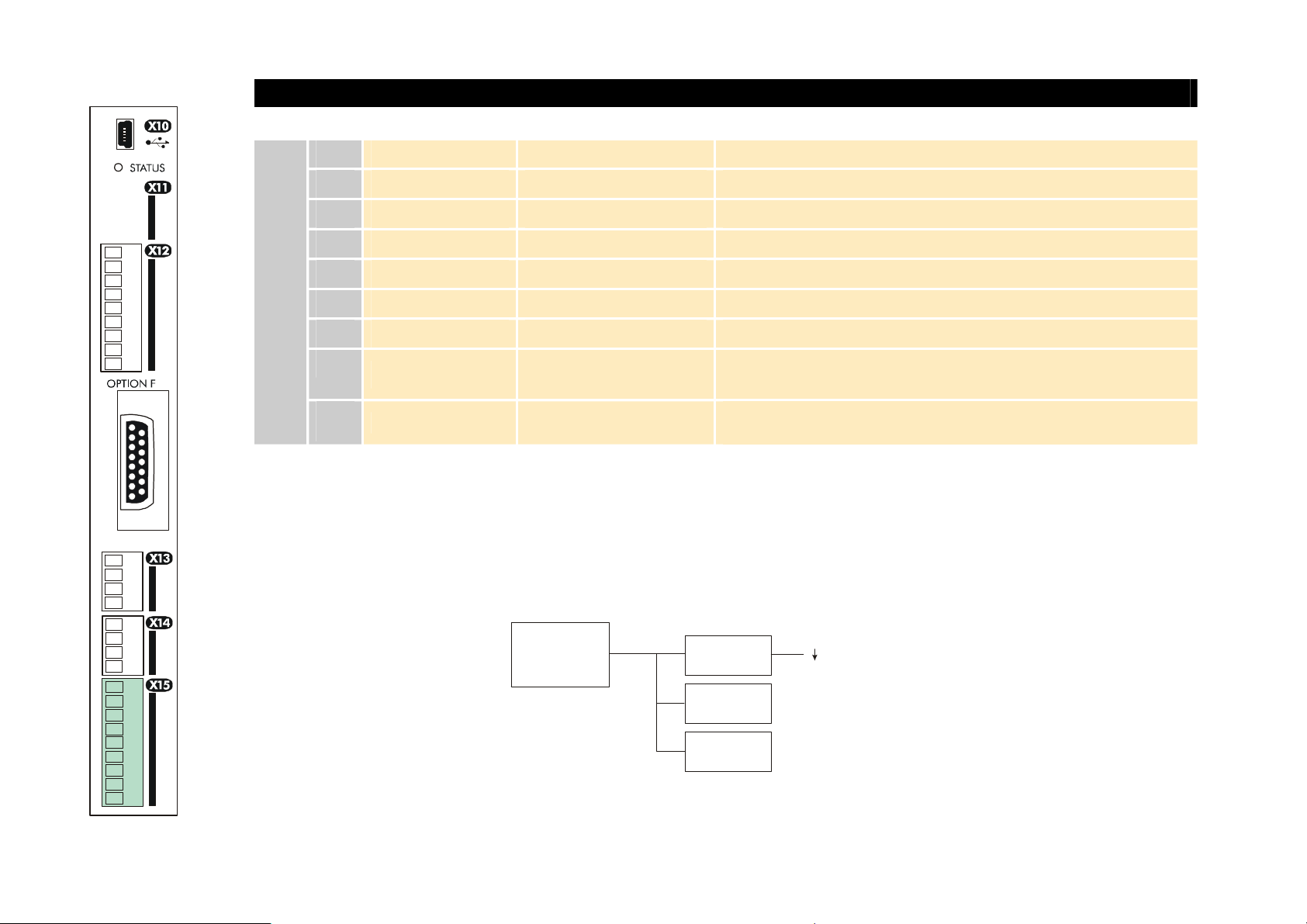
C h a p t e r 3 : I n s t a l l i n g t h e D r i v e 3-25
DIGITAL I/O
X15
All digital inputs/outputs are configurable using the DSE 890 (Drive System Explorer) Configuration Tool supplied on disk.
The table shows the factory defaults. The digital inputs require 24V DC which is supplied at terminal X14/03. For further
information refer to the DSE 890 Configuration Tool.
NOTE The maximum permissible sum of currents from X14/03, X15/08, X15/09 is 150mA. The load on X15/08 & X15/09
connects from these pins to X14/04 (0V). An Alert message will be displayed if exceeded.
Name Range Description
DIN1 0-24V DC Digital Input 1 (default = JOG)
01
DIN2 0-24V DC Digital Input 2 - (default = RUN)
02
DIN3 0-24V DC Digital Input 3 - (default = STOP)
03
DIN4 0-24V DC Digital Input 4 - (default = REVERSE)
04
DIN5 0-24V DC Digital Input 5 - (default = TORQUE MODE)
05
DIN6 0-24V DC Digital Input 6 - (default = unassigned)
06
DIN7 0-24V DC Digital Input 7 - (default = unassigned)
07
08
DIN8/DOUT1 0-24V DC
09
DIN9/DOUT2 0-24V DC
Digital Input/output 1 (default = digital output: RUNNING)
Digital Input/output 2 (default = digital output: ZERO SPEED)
AC890PX AC Drive
SUPPLY
150mA
X14/03
X15/01
(7mA each)
X15/07
X15/08
X15/09
Page 48
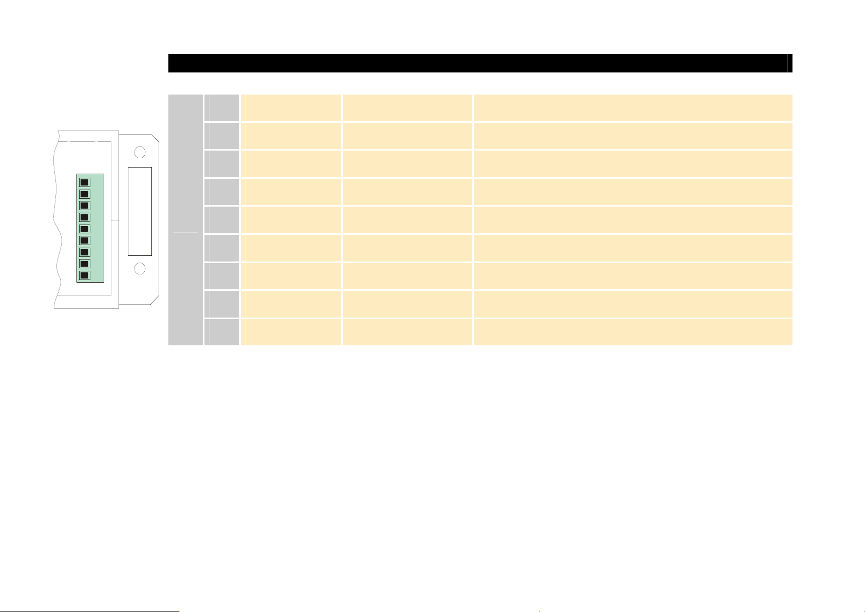
3-26 C h a p t e r 3 : I n s t a l l i n g t h e D r i v e
DIGITAL I/O
X16
01
02
03
04
05
06
07
08
09
X16
Name Range Description
DOUT4A open/closed Normally-open relay contacts, A & B.
01
DOUT4B open/closed Default function DOUT4 closed = healthy
02
DOUT5A open/closed Normally-open relay contacts, A & B.
03
DOUT5B open/closed Default function DOUT5 closed = running
04
DOUT6A open/closed Normally-open relay contacts, A & B.
05
DOUT6B open/closed No default function.
06
- - UNUSED
07
MTR THERM A - Motor Thermistor, or link terminals X16/08 & X16/09
08
MTR THERM B - Motor Thermistor, or link terminals X16/08 & X16/09
09
All digital inputs/outputs are configurable using the DSE 890 (Drive System Explorer) Configuration Tool supplied on disk.
The table shows the factory defaults. The digital inputs require 24V DC which is supplied at terminal X14/03. For further
information refer to the DSE 890 Configuration Tool.
Relay outputs are volt-free, normally open contacts. Rated to 240V 3A resistive load. Alternatively they may be used down to
1mA, 12V levels.
AC890PX AC Drive
Page 49

C h a p t e r 3 : I n s t a l l i n g t h e D r i v e 3-27
Step 3: Powering-Up the Unit
NOTE Refer to "USER 24V DC INPUTS", page 3-23 for details about configuring and commissioning the drive without
connecting 3-phase power supply. Continue reading from "3.3: Configure the AC890PX AC Drive", page 3-28.
Main Points
1. Complete all Pre-Operation Checks.
2. Ensure all the set-up parameter values for each AC890PX AC Drive have been entered. Refer to "Set-up Parameters"
page 3-30.
3. Autotune the drive where necessary.
4. Save your Application.
5. Follow one of the Start-up Routines: Local Mode or Remote Mode.
3.1: Pre-Operation Checks
Before Applying Power:
AC890PX AC Drive
Read the Safety section at the front of the Manual.
• Ensure that all local electric codes are met.
• Check for damage to equipment.
• Check for loose ends, clippings, drilling swarf etc. lodged in the drive and system.
• Check all external wiring circuits of the system - power, control, motor and earth connections.
• Ensure that unexpected rotation of the motor in either direction will not result in damage, bodily harm or injury.
Disconnect the load from the motor shaft, if possible.
• Check the state of the Motor Thermistor and External Brake Resistor connectors. Check external run contacts are
open. Check external speed setpoints are all at zero.
• Ensure that nobody is working on another part of the system which will be affected by powering up.
• Ensure that other equipment will not be adversely affected by powering up.
• Check motor stator connections are correctly wired for Star or Delta as necessary for drive output voltage.
Page 50
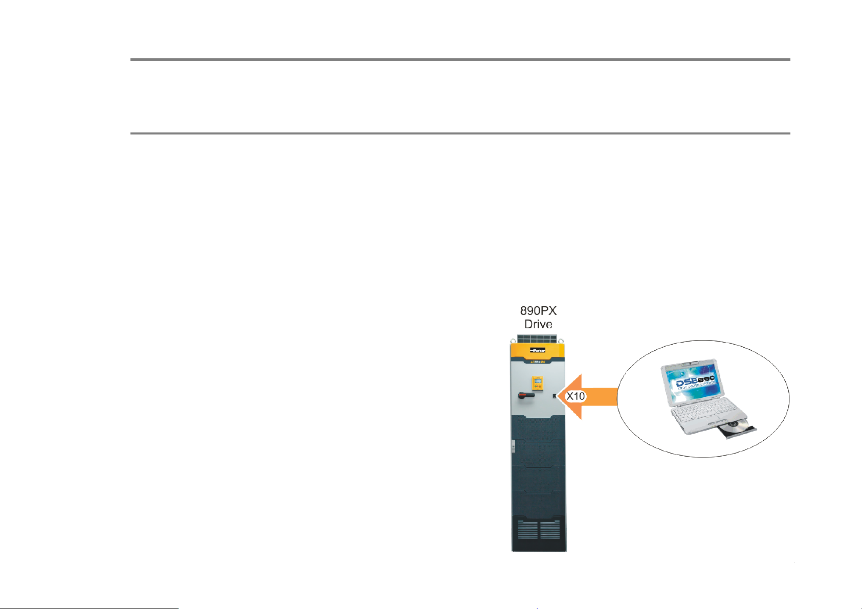
3-28 C h a p t e r 3 : I n s t a l l i n g t h e D r i v e
3.2: Apply the 3-Phase Supply
Fit the supply fuses and apply the 3-phase supply to the AC890PX AC Drive.
3.3: Configure the AC890PX AC Drive
You must now configure the AC890PX AC Drive to your application. To do this, use the DSE 890 Configuration Tool
supplied on the CD (recommended), or the Keypad.
Configure the Drive using DSE 890
The DSE 890 (Drive System Explorer) Configuration Tool has a full Help system. Insert the DSE 890 disk into your PC and
follow the on-screen instructions. Use the tool to set-up the I/O connectivity so that it meets the requirements for the
AC890PX AC Drive. When connected, enter the set-up parameters as discussed on page 3-30.
Connecting to a PC
Connect the AC890PX AC Drive via the USB port on the front
of the drive to your PC using an approved USB lead.
AC890PX AC Drive
Page 51
C h a p t e r 3 : I n s t a l l i n g t h e D r i v e 3-29
Configure the Drive using the Keypad
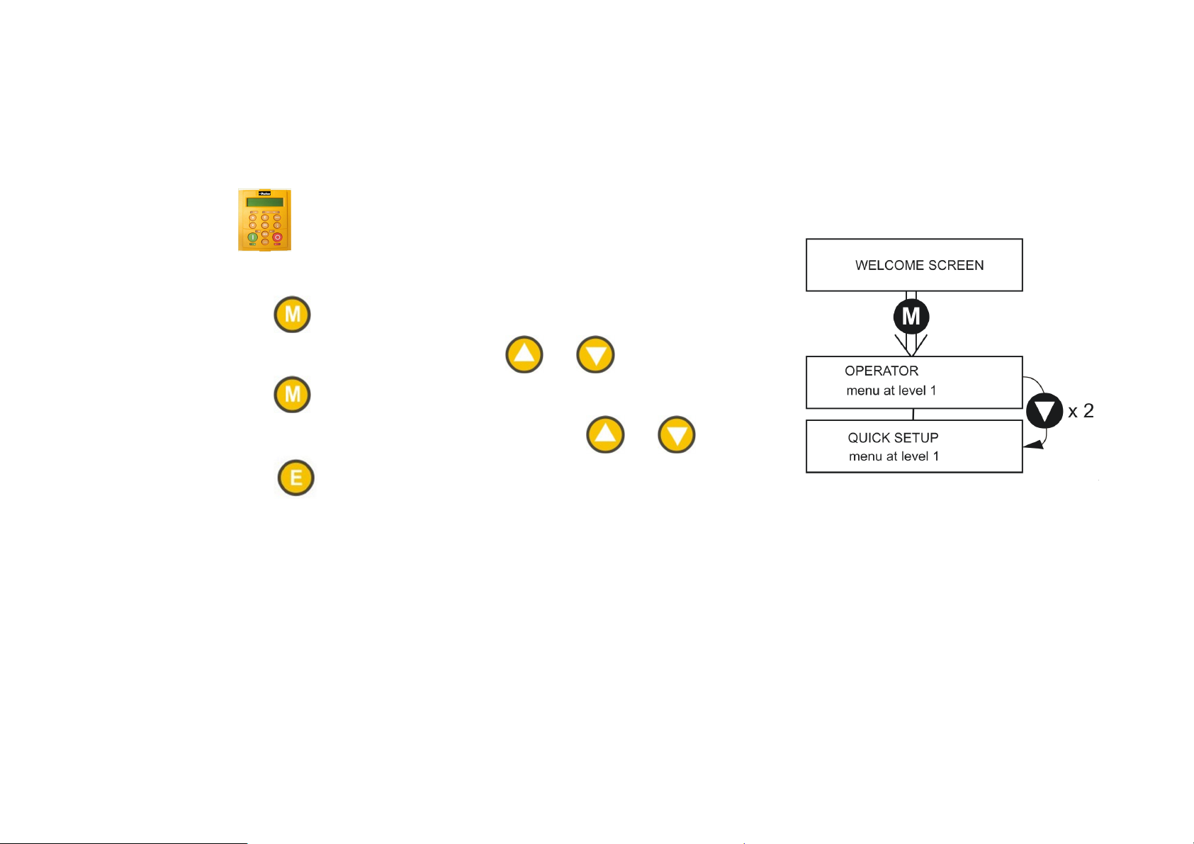
Fit the keypad to the front of the unit, or connect remotely. Select LOCAL mode operation on the Keypad by pressing the
L/R key (LOCAL/REMOTE) until the SETPOINT (LOCAL) parameter is displayed. The set-up parameters are stored in the
QUICK SETUP menu. Now enter the set-up parameters as discussed on page 3-30.
6901 Keypad
How to Edit a Parameter
Press to enter the QUICK SETUP menu.
Scroll through the parameters using the and
Press to select a parameter for editing.
Increment/decrement the parameter value using the and keys.
Press to exit the parameter.
keys.
AC890PX AC Drive
Page 52

3-30 C h a p t e r 3 : I n s t a l l i n g t h e D r i v e
Set-up Parameters
The drive has several control modes:
Control Modes
V/Hz
SV
CLV
VOLTS / HZ Set-up as an Open-Loop Drive (V/F Fluxing) - low performance applications (fan, pump).
Simplest method involving no speed feedback and no compensation for load changes.
Autotune is not required.
SENSORLESS
VEC
CLOSED-LOOP
VEC
Set-up using the Sensorless Vector Fluxing Mode - medium performance applications
where the drive uses an electrical model of the motor to automatically compensate for load
changes.
The drive must be tuned to the motor in use by matching the motor parameters in the drive
to those of the motor being controlled.
You MUST use the Autotune feature after entering your parameter values.
Set-up using the Closed-Loop Vector Mode - high performance applications where the
drive uses external sensors (encoders) to automatically compensate for load changes.
In this mode, speed feedback signals from the motor shaft encoder are processed to
determine the rotational speed of the shaft. A PI algorithm within the software uses this
information to produce varying gate drive signals to the drive circuits. These signals cause
the drive to output the required voltage and frequency for a particular motor speed.
You MUST use the Autotune feature after entering your parameter values.
AC890PX AC Drive
Page 53

C h a p t e r 3 : I n s t a l l i n g t h e D r i v e 3-31
Control Modes
4-Q
PMAC
4-Q REGEN
PMAC
Set-up using 4Q Regen active front end (AFE) control mode.
DO NOT SELECT THIS CONTROL MODE FOR AC890PX.
Set-up using PMAC (Permanent Magnet AC) servo or torque motor control mode - a high
performance application where the drive uses Resolver or Sin/Cos Encoder motor
feedback.
In this mode, speed feedback signals from the motor shaft encoder are processed to
determine the rotational speed of the shaft. A PI algorithm within the software uses this
information to produce varying gate drive signals to the drive circuits. These signals cause
the drive to output the required voltage and frequency for a particular motor speed.
Autotune is not required.
The Motor Selection Wizard in the 890 DSE Configuration Tool MUST be used to
correctly set-up the motor and feedback device parameters. Failure to do so may result in
damage to the servo motor.
AC890PX AC Drive
Page 54

3-32 C h a p t e r 3 : I n s t a l l i n g t h e D r i v e
The following is a list of the Set-up parameters you may need to check before starting the drive. Set only the ones marked
with "x" for the intended mode of operation.
NOTE Parameters whose values are "product code dependent" will have a typical value for the size of unit. Where possible
(or required), enter an application-specific value for improved performance, otherwise use the typical value.
NOTE "PREF" is a parameter reference number used by the DSE 890 Configuration Tool.
SET-UP PARAMETERS
PREF 6911Display
136.02 CONTROL MODE 0 : VOLTS / HZ
101.08 MAX SPEED product code dependent The maximum speed
100.02 RAMP ACCEL TIME 10.0 s Acceleration time from 0
1 : SENSORLESS VEC
2 : CLOSED-LOOP VEC
Default
3 : 4-Q REGEN
4 : PMAC*
Brief Description
Select the operating mode
for the drive.
* If PMAC control is
required, the motor wizard
feature in the 890 DSE
Configuration Tool MUST
be used to correctly set-up
the motor and feedback
device parameters. Failure
to do so may result in
damage to the servo
motor.
clamp and scale factor for
other speed parameters (at
full process speed)
rpm to MAX SPEED
V/Hz SV CLV 4-Q PMAC
x
(0) x (1)
x x x x
x x x x x
x
(2)
x
(3)
x
(4)
100.03 RAMP DECEL TIME 10.0 s Deceleration time from
MAX SPEED to 0 rpm
x x x x x
AC890PX AC Drive
Page 55

C h a p t e r 3 : I n s t a l l i n g t h e D r i v e 3-33
SET-UP PARAMETERS
PREF 6911Display
102.01 RUN STOP MODE 0 : RUN RAMP
103.01 JOG SETPOINT 10.0 % Drive speed setpoint whilst
21.01 V/F SHAPE 0 : LINEAR LAW
70.01 QUADRATIC
TORQUE
27.05 MOTOR CURRENT product code dependent Enter the motor full load
2 : DC INJECTION
2 : USER DEFINED
Default
1 : COAST
3 : STOP RAMP
1 : FAN LAW
0 : FALSE
1 : TRUE
Brief Description
Selects the stopping mode
used by the drive
jogging (percentage of
MAX SPEED)
Sets the type of volts to
frequency template that is
used to flux the motor
0 : FALSE = Constant
Selects between Constant
or Quadratic mode of
operation
current from the motor
nameplate
V/Hz SV CLV 4-Q PMAC
x x x x x
x x x x x
x
x x x x
x x x x
21.03 FIXED BOOST product code dependent Boosts starting torque by
adding volts at low speed
82.01 CURRENT LIMIT 150.00% Level of motor current as %
of FULL LOAD CALIB
81.01 VOLTAGE MODE None Defines how volts Hz
characteristic varies in
response to changes in DC
link voltage.
27.02 POWER product code dependent Nameplate induction
motor power
AC890PX AC Drive
x
x x x x
x x x x
x x x
Page 56

3-34 C h a p t e r 3 : I n s t a l l i n g t h e D r i v e
27.03 MOTOR BASE
FREQUENCY
27.04 MOTOR VOLTAGE product code dependent Enter the motor nameplate
27.07 NAMEPLATE RPM product code dependent Enter the motor nameplate
27.09 MOTOR POLES product code dependent
27.08 MOTOR
CONNECTION
product code dependent Enter the motor nameplate
base frequency
voltage at base frequency
full-load rated speed. This
is the motor speed in rpm
at base frequency minus
full load slip.
Enter the number of motor
0 : 2 pole
1 : 4 pole
2 : 6 pole
3 : 8 pole
4 : 10 pole
5 : 12 pole
product code dependent
0 : DELTA
1 : STAR
poles from the motor
nameplate
Enter the type of motor
connection
x x x
x x x
x x x
x x x
x x
71.01 PULSE ENC VOLTS product code dependent Set between 10-20V to
match the encoder supply
voltage
71.02 ENCODER LINES product code dependent
71.03 ENCODER INVERT 0 : FALSE
1 : TRUE
Rotating Autotune sets
actual value
Set to the number of lines
used by the encoder
Encoder direction :- when
TRUE, changes the sign of
the measured speed and
the direction of the position
count.
x
x
x
AC890PX AC Drive
Page 57

C h a p t e r 3 : I n s t a l l i n g t h e D r i v e 3-35
80.01
80.02
27.06 MAG CURRENT product code dependent
27.14 STATOR RES product code dependent
27.15 LEAKAGE INDUC product code dependent
27.16 MUTUAL INDUC product code dependent
AUTOTUNE
ENABLE
AUTOTUNE MODE
Rotating Autotune sets
0 : FALSE
1 : TRUE
0 : ROTATING
1 : STATIONARY
2 : SPD LOOP
ROTATING
3 : SPD LOOP
STATIONARY
actual value
Autotune sets actual
value
Autotune sets actual
value
Autotune sets actual
value
Set TRUE to enable
Autotune. Resets to FALSE
when complete.
Set the type of Autotune. x x
Enter the No-Load Amps
from the motor nameplate
Motor per-phase stator
resistance
Motor per-phase stator
leakage inductance
Motor per-phase stator
mutual (magnetising)
inductance
x
x x x
x x
x x
x x
27.17 ROTOR TIME
CONST
78.01 SPEED PROP GAIN 20.0 Sets the proportional gain
78.02 SPEED INT TIME 100 ms The integral time constant
AC890PX AC Drive
product code dependent
Autotune sets actual
value
The motor model rotor
time constant as
determined by Autotune
of the loop
of the speed loop
x x
x x x
x x x
Page 58

3-36 C h a p t e r 3 : I n s t a l l i n g t h e D r i v e
1.03 A1N1 TYPE 0 : -10..+10 V
1 : 0..+10 V
2.03 AIN2 TYPE 0 : -10..+10 V
1 : 0..+10 V
3.03 AIN3 TYPE 0 : -10..+10 V
1 : 0..+10 V
2 : 0..20 mA
3 : 4..20 mA
4.03 AIN4 TYPE 0 : -10..+10 V
1 : 0..+10 V
2 : 0..20 mA
3 : 4..20 mA
97.01 DISABLED WORD 1
97.02 DISABLED WORD 2
0700 >> Indicates which trips have
0840 >> Indicates which trips have
Select the input range and
type
Select the input range and
type
Select the input range and
type
Select the input range and
type
been disabled - refer to
Chapter 10
been disabled - refer to
Chapter 8
x x x x x
x x x x x
x x x x x
x x x x x
x x x x x
x x x x x
31.01 VIEW LEVEL 0 : BASIC
1 : OPERATOR
2 : ADVANCED
Selects full menu for MMI
display
x x x x x
AC890PX AC Drive
Page 59
C h a p t e r 3 : I n s t a l l i n g t h e D r i v e 3-37
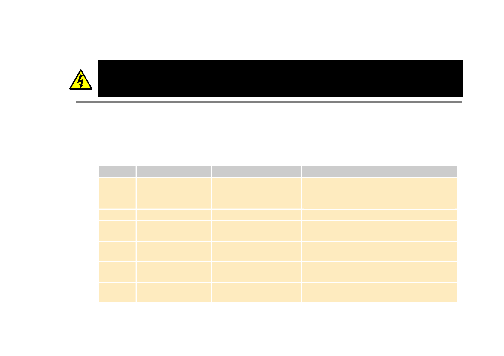
Step 4: Run the Motor
WARNING
Remove the fuses (or trip the circuit breaker) on your 3-phase supply.
Make sure the power is OFF, and that it cannot be switched on accidentally whilst you are working.
Allow at least 10 minutes for the drive's capacitors to discharge to safe voltage levels (<50V).
4.1: The Autotune Feature
NOTE You MUST carry out an Autotune, unless the drive is in Volts/Hz Mode (Open-Loop Drive) or in PMAC control mode
(Autotune will not perform in these modes as it is unnecessary - go to page 3-42).
The Autotune feature identifies motor characteristics to allow the drive to control the motor.
It loads the values into the parameters below, which are in the QUICK SETUP menu.
PREF Parameter Description Note
71.03 ENCODER INVERT Encoder direction Parameter is only set up if drive is configured to
run as Closed-loop Vector
AC890PX AC Drive
Not measured by Stationary Autotune
27.06 MAG CURRENT Magnetising current Not measured by Stationary Autotune
27.14 STATOR RES Per phase stator
resistance
27.15 LEAKAGE INDUC Per phase stator leakage
inductance
27.16 MUTUAL INDUC Per phase mutual
inductance
27.17 ROTOR TIME CONST Rotor time constant This is identified from magnetising current and
For further information on the functions of all parameters, refer to Appendix D: "Programming".
motor nameplate rpm
Page 60

3-38 C h a p t e r 3 : I n s t a l l i n g t h e D r i v e
Stationary or Rotating Autotune?
Will the motor spin freely, i.e. not connected to a load, during the Autotune?
• If it can spin freely, use a Rotating Autotune (preferred)
• If it cannot spin freely, use a Stationary Autotune
Action Requirements
Rotating Autotune
Preferred method
Stationary Autotune
Only used when the motor
cannot spin freely during the
Autotune feature
Spins the motor up to the maximum
speed set by the user to identify all
necessary motor characteristics
Motor does not spin during Autotune. A
limited set of motor characteristics are
identified
Motor must spin freely during Autotune
You must enter the correct value of
magnetising current
Do not subsequently operate the drive above
base speed
In Closed-loop Vector Mode set up the
encoder direction parameter
Necessary Data
You MUST enter values for the following parameters, found in the QUICK SETUP menu, before an Autotune can be carried
out:
MOTOR CURRENT
MOTOR BASE FREQ
MOTOR VOLTAGE (maximum motor output voltage)
NAMEPLATE RPM (motor nameplate speed)
MOTOR POLES (the number of motor poles)
ENCODER LINES (if an encoder is fitted, enter the number of lines used by the encoder)
AC890PX AC Drive
Page 61

C h a p t e r 3 : I n s t a l l i n g t h e D r i v e 3-39
Performing a Rotating Autotune
NOTE The drive will not perform an Autotune when in Volts/Hz Mode (Open-Loop Drive.) An Autotune is not necessary in
this control mode.
Check that the motor can rotate freely in the forward direction. Ensure also that the motor is unloaded. Ideally, the motor
shaft should be disconnected. If the motor is connected to a gearbox this is okay, provided that there is nothing on the output
of the gearbox which could load the motor.
1. In the QUICK SETUP menu, set MAX SPEED to the maximum speed at which you will operate the drive in normal
operation. The Autotune will characterise the motor up to 30% above this speed. If you later wish to run faster than this,
you will need to carry out another Autotune.
2. Set AUTOTUNE ENABLE to TRUE, and start the drive . The drive will carry out a Rotating Autotune (indicated by
the Run and Stop led’s flashing. This may take several minutes, during which the motor will be accelerated to maximum
speed and then brought to a stop. When complete, the drive is returned to the stopped condition and the AUTOTUNE
ENABLE parameter is reset to FALSE. In Closed-loop Vector mode (with an encoder) the encoder sign has been adjusted
by the Autotune feature.
IMPORTANT
AC890PX AC Drive
Now perform a SAVE CONFIG to save your new settings. Refer to Chapter 6: “The Keypad” - SAVE CONFIG.
Page 62

3-40 C h a p t e r 3 : I n s t a l l i n g t h e D r i v e
Performing a Stationary Autotune
NOTE The drive will not perform an Autotune when in Volts/Hz Mode (Open-Loop Drive.) An Autotune is not necessary in
this control mode.
Before starting the stationary Autotune, you MUST enter the value of magnetising current for the motor. This may be
available on the motor nameplate. If not, you may need to contact the motor supplier.
1. In the QUICK SETUP menu, set the AUTOTUNE MODE parameter to STATIONARY (0).
2. Set ENABLE to TRUE, and start the drive . The drive will carry out a stationary Autotune, injecting current into the
motor but not turning the shaft. The Run and Stop led’s will flash. When complete, the drive is returned to the stopped
condition and the AUTOTUNE ENABLE parameter is reset to FALSE.
IMPORTANT
Now perform a SAVE CONFIG to save your new settings. Refer to Chapter 6: “The Keypad” - Quick Save Feature.
• If the drive is configured to run in Sensorless Vector mode, set-up is complete.
• If the drive is configured to run in Closed-loop Vector mode, i.e. using an encoder, then the encoder direction must be set
up. Refer to “Setting the Encoder Sign” below.
AC890PX AC Drive
Page 63

C h a p t e r 3 : I n s t a l l i n g t h e D r i v e 3-41
Setting the Encoder Sign (Closed-Loop Vector Mode)
If you have performed a Stationary Autotune in Closed-loop Vector mode, you should check the encoder direction as follows:
Look and listen to the motion of the motor when the drive is running at a speed demand of between 5 - 10%.
As a test, use the Rotary Controller (S) key on the MMI to increase the speed to about double the original figure. Change the
direction of rotation using the FWD/REV control key.
If ENCODER INVERT is correct, the motor will rotate smoothly and will respond to the changes in speed demand and
direction.
If ENCODER INVERT is incorrect, the motor will rotate in a jerky and/or noisy manner. Alternatively, it may rotate
smoothly at a very low speed but not respond to changes in speed demand or direction.
• Change the setting of ENCODER INVERT to change the encoder sign.
• Change the direction of rotation back to the original direction. Re-set the speed demand.
The encoder sign is now correct for the original motor direction.
If however the direction of the motor is incorrect at this point, then power down the entire drive, wait for 3 minutes (for the dc
link capacitors to discharge) and then swap the motor drive cables M1/U and M2/V. Change the setting of ENCODER
INVERT.
IMPORTANT
AC890PX AC Drive
The encoder sign is now correct for the new motor direction.
Now perform a SAVE CONFIG to save your new settings. Refer to Chapter 6: “The Keypad” - Quick Save Feature.
Page 64

3-42 C h a p t e r 3 : I n s t a l l i n g t h e D r i v e
4.2: Initial Start-Up Routines
Unpredictable motion, especially if motor parameters are incorrect.
Ensure no personnel are in the vicinity of the motor or any connected machinery.
Ensure that no machinery connected to the motor will be damaged by unpredictable motion.
Ensure that the emergency stop circuits function correctly before running the motor for the first time.
The Routines 1 & 2 below will run the drive in the default V/F fluxing control mode (VOLTS / HZ) to begin with using
either the Keypad or the Control Terminals.
Now perform a SAVE CONFIG to save your new settings. Refer to Chapter 6: “The Keypad” - Quick Save Feature
Routine 1: Local Mode
NOTE Refer to Chapter 6: “The Keypad” to familiarise yourself with the keypad and menu structure.
Local control has a use for commissioning a drive. It is not the expected way to operate a system drive.
WARNING
On the AC890PX AC Drive's keypad:
1. Select Local Mode (select LOCAL mode operation on the Keypad by pressing the L/R key (LOCAL/REMOTE) until the
SETPOINT (LOCAL) parameter is displayed).
2. The drive should be "healthy" now it is powered-up: no flashing trip messages displayed, and the keypad's HEALTH LED
is lit (the RUN LED remains off). The keypad will display the Remote Setpoint parameter.
If the drive has tripped, the keypad will be flashing a trip message, and the keypad's HEALTH LED will flash. Refer to
Chapter 8: “Trips and Fault Finding” to investigate and remove the cause of the trip.
AC890PX AC Drive
Page 65
C h a p t e r 3 : I n s t a l l i n g t h e D r i v e 3-43
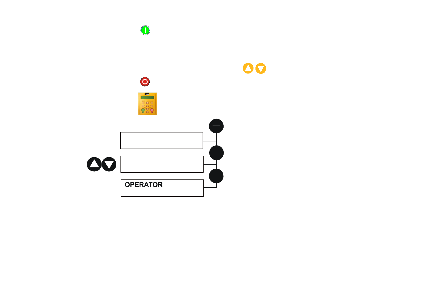
3. Press the Start key
the setpoint is at zero).
Reverse the motor’s direction of rotation either by pressing the W X key on the keypad, or by swapping two of the motor
phases (WARNING: Disconnect the mains supply first).
4. Control the value of the Local Setpoint parameter using the
5. Press the Stop key .
SETPOINT (LOCAL)
Æ
. The keypad's RUN LED will light and the motor will rotate slowly (the RUN LED will flash if
6901 Keypad
L
R
keys.
10.0 %
M
SETPOINT (LOCAL)
Æ
10.0 %
x 2
E
AC890PX AC Drive
menu at level 1
Page 66

3-44 C h a p t e r 3 : I n s t a l l i n g t h e D r i v e
Routine 2: Remote Mode
This routine assumes that the drive’s control terminals are wired as shown in "Full Connection Diagram" on page 3-18.
IMPORTANT
Ensure that the speed potentiometer is set to zero.
On the AC890PX AC Drive:
1. The drive should be "healthy" now it is powered-up: no flashing trip messages displayed, and the keypad's HEALTH LED
is lit (the RUN LED remains off).
If the drive has tripped, the keypad will be flashing a trip message, and the keypad's HEALTH LED will flash. Refer to
Chapter 8: “Trips and Fault Finding” to investigate and remove the cause of the trip.
2. Select Remote Mode - refer to Chapter 6: "The Keypad" for details, or power-down and power up the unit to re-initialise
in Remote mode.
3. To Start in Remote Mode, close the "Run" switch on your control panel (applying 24V to DIN2, terminal X15/02 -
RUN).
4. Turn the speed potentiometer up a little to apply a small speed setpoint (applying a variable voltage to AIN3, terminal
X12/04 - REMOTE SETPOINT). The keypad's RUN LED will light and the motor will rotate slowly (the RUN LED will
flash if the setpoint is at zero).
Reverse the motor’s direction of rotation either by pressing the W X key on the keypad, or by swapping two of the motor
phases (WARNING: Disconnect the mains supply first).
5. To Stop in Remote Mode, open the "Run" switch on your control panel (removing 24V from DIN2, terminal X15/02 -
RUN).
AC890PX AC Drive
Page 67

C h a p t e r 4 : A s s o c i a t e d E q u i p m e n t 4-1
t
C h a p t e r
A s s o c i a t e d E q u i p m e n
4
Details for all the ancillary parts of a system that can be used with the 890.
AC890PX AC Drive
Page 68
4-2 C h a p t e r 4 : A s s o c i a t e d E q u i p m e n t
Main Points
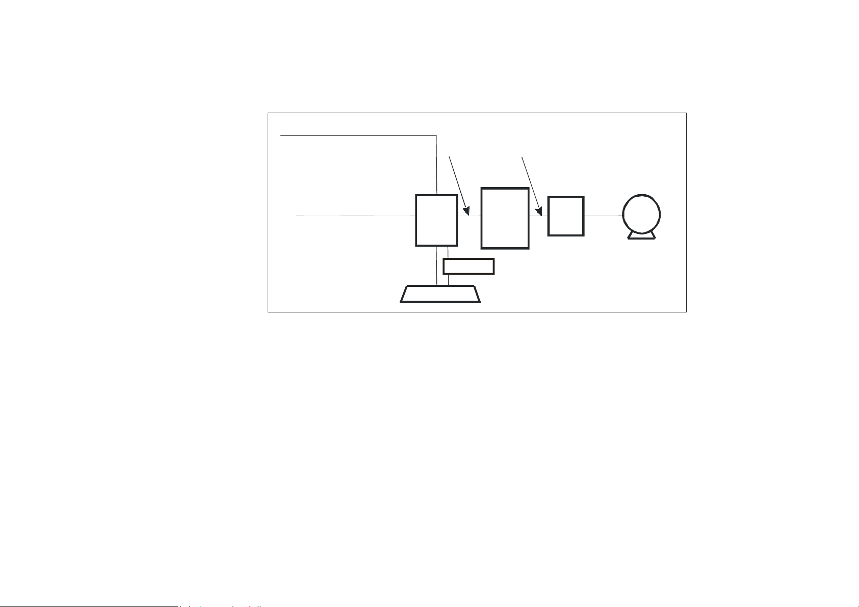
Connect the associated equipment in the following order:
signal/control
(sensitive)
power
supply
cable
(clean)
cable
(noisy)
890PX
(noisy)
brake resistor
Overload
(noisy)
EMC
motor
output
filter
EMC Motor Output Filter
This can help the drive achieve EMC and filter thermal conformance. It also ensures longer motor life by reducing the high
voltage slew rate and overvoltage stresses. Mount the filter as close to the VSD as possible. Please refer to Parker SSD Drives
for the selection of a suitable filter.
motor
choke
motor
cable
(noisy)
motor
890PX
Motor Choke
Maximum Motor dv/dt = 10,000V/μs. This can be reduced (when cabling is over 50m in length - to a maximum of 300m) by
adding a motor choke in series with the motor.
Installations with long cable runs may suffer from nuisance overcurrent trips. A choke may be fitted in the drive output to
limit capacitive current. Screened cable has a higher capacitance and may cause problems in shorter runs. Contact Parker SSD
Drives for recommended choke values.
AC890PX AC Drive
Page 69

C h a p t e r 4 : A s s o c i a t e d E q u i p m e n t 4-3
(
)
( )
External Braking Resistors
Main Points
♦ We recommend using a thermal overload switch to protect the braking circuit. Refer to page 4-5.
♦ Use the DSE 890 Configuration Tool to configure the following parameters in the AC890PX drive:
Set the INT DB RESISTOR parameter (PREF 31.75 in the DYNAMIC BRAKING function block) to FALSE. Also
enter information about the external resistor being used in to this function block. Enable the "Brake Resistor" and
"Brake Switch" trips in the TRIPS STATUS function block (DISABLE TRIPS parameter).
IMPORTANT
Calculation
The continuous rating quoted is not to be exceeded under repetitive loading.
Brake resistor assemblies must be rated to absorb both peak braking power during deceleration and the average power over
the complete cycle.
Peak braking power P
J - total inertia (kgm2)
n
Average braking power P
t
t
Obtain information on the peak power rating and the average power rating of the resistors from the resistor manufacturer. If
this information is not available, a large safety margin must be incorporated to ensure that the resistors are not overloaded.
By connecting these resistors in series and in parallel the braking capacity can be selected for the application.
00055 n n
.
=
pk
av
×
J
P
pk
=
x tb n
t
c
2
× −
1
t
b
2
2
W
- initial speed (rpm)
1
- final speed (rpm)
2
- braking time (s)
b
- cycle time (s)
c
AC890PX AC Drive
Page 70
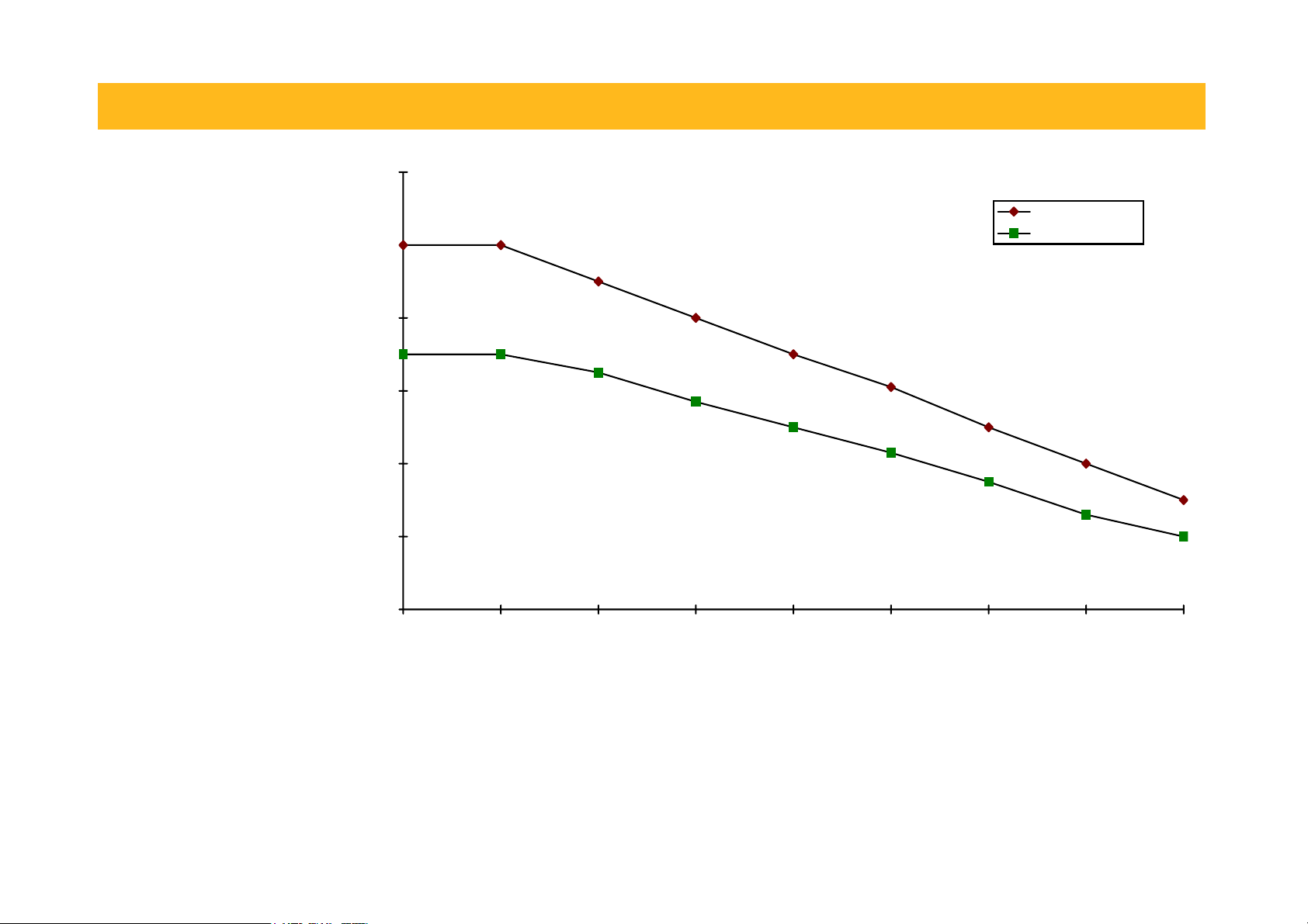
4-4 C h a p t e r 4 : A s s o c i a t e d E q u i p m e n t
IMPORTANT
The minimum resistance of the combination and maximum dc link voltage must be as specified in Appendix E:
“Technical Specifications” - Internal Dynamic Brake Switch.
120
100
80
% of Rated Power
60
40
20
chassis mounted
free air
0
0 25 50 75 100 125 150 175 200
Ambient Temp (C)
Figure 3.1 Braking Resistor Derating Graph (Metal Clad Resistors)
AC890PX AC Drive
Page 71

C h a p t e r 4 : A s s o c i a t e d E q u i p m e n t 4-5
Dynamic Brake Resistor Overload Protection
We recommend that the braking resistor and wire are protected by a motor circuit protector rated at 110% of the continuous
current rating of the resistor(s).
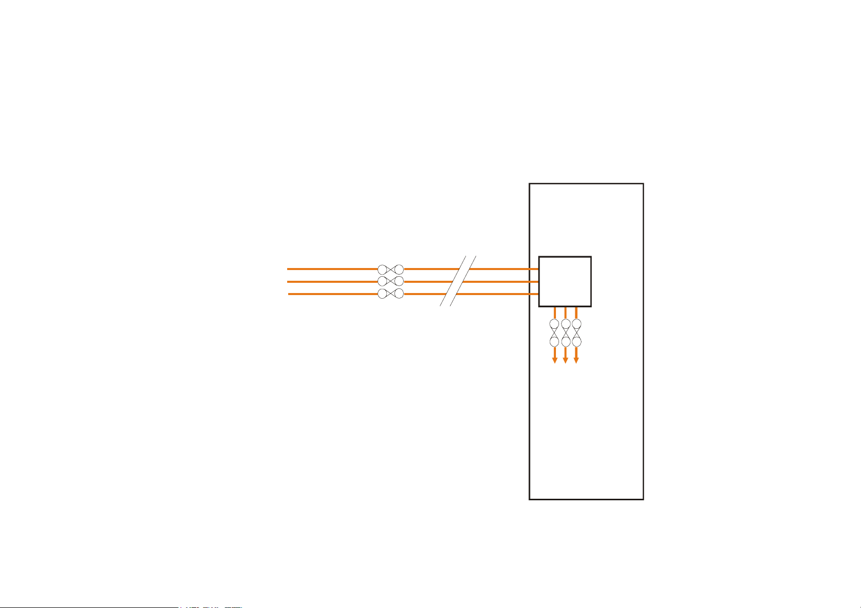
Route the braking wire through all three poles of the Dynamic Brake Resistor Overload Protection (part number
DC471346U032). An auxiliary contact can be used to annunciate an alarm if a trip should occur.
NOTE Intermediate overload circuit breakers are available if required:
DB388422 - 6V2ME16 - 9 to 14A
DB388425 - 6V2ME22 - 20 to 25A
AC890PX AC Drive
Page 72
4-6 C h a p t e r 4 : A s s o c i a t e d E q u i p m e n t
Branch Circuit Protection
The AC890PX is supplied with an Isolator.
Branch circuit protection must be provided upstream in the 3-phase supply to the drive. Use slow-blow fuses, rated to protect
the cable in the event of a short-circuit. Refer to "Circuit Breakers" below.
Branch
L1
L2
L3
Protection
Circuit
SLOW
BLOW
FUSES
ISOLATOR
SEMICONDUCTOR
FUSES
AC890PX
890PX
AC890PX AC Drive
Page 73

C h a p t e r 4 : A s s o c i a t e d E q u i p m e n t 4-7
Circuit Breakers
Circuit breakers (e.g. RCD, ELCB, GFCI), must:
• Operate correctly with dc and ac protective earth currents (i.e. type B RCDs as in Amendment 2 of IEC755).
• Have adjustable trip amplitude and time characteristics to prevent nuisance tripping on switch-on.
High frequency and dc components of earth leakage currents will flow under normal operating conditions. Under certain fault
conditions larger dc protective earth currents may flow. The protective function of some circuit breakers cannot be guaranteed
under such operating conditions.
WARNING
Circuit breakers used with VSDs and other similar equipment are not suitable for personnel protection. Use
another means to provide personal safety. Refer to EN60204-1
AC890PX AC Drive
Page 74

4-8 C h a p t e r 4 : A s s o c i a t e d E q u i p m e n t
AC890PX AC Drive
Page 75

C h a p t e r 5 : O p e r a t i n g t h e D r i v e 5-1
C h a p t e r
O p e r a t i n g t h e D r i v e
Having turned the motor for the first time, now learn about the various ways you can
start and stop the drive. This chapter also offers some application advice.
5
AC890PX AC Drive
Page 76
5-2 C h a p t e r 5 : O p e r a t i n g t h e D r i v e
Control Philosophy
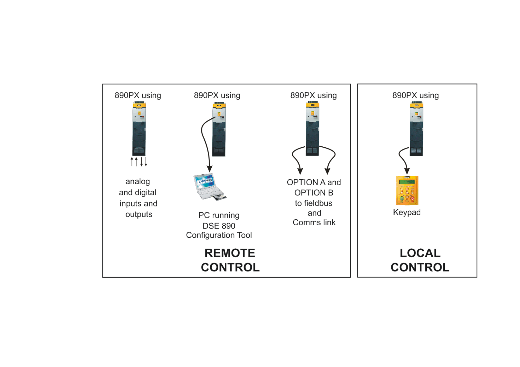
There are four ways to control the drive using Remote and Local control:
Figure 3.1
Remote and Local Control Modes
AC890PX AC Drive
Page 77

C h a p t e r 5 : O p e r a t i n g t h e D r i v e 5-3
Start/Stop and Speed Control
There are two forms of control in operation at any time: Start/Stop and Speed Control. Each can be individually selected to be
under either Local or Remote Control.
• Local or Remote Start/Stop decides how you will start and stop the drive.
• Local or Remote Speed Control determines how you will control the motor speed.
In each case, Local and Remote control are offered by using the following:
Local: The Keypad
Remote: Analog and digital inputs and outputs, RS232 Port or Technology Options
NOTE Refer to Appendix D: "Programming" - LOCAL CONTROL.
AC890PX AC Drive
Page 78
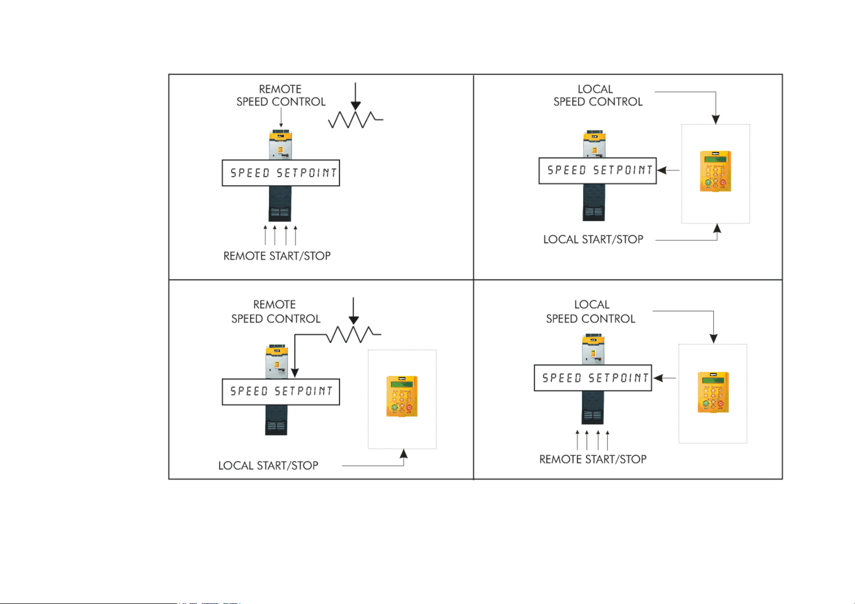
5-4 C h a p t e r 5 : O p e r a t i n g t h e D r i v e
Thus the drive can operate in one of four combinations of local and remote modes:
Figure 3.2 The Four Combinations of Local and Remote Control
NOTE Start/Stop is also known as “Sequencing”.
Speed Control is also known as “Reference Generation”.
AC890PX AC Drive
Page 79

C h a p t e r 5 : O p e r a t i n g t h e D r i v e 5-5
The Start/Stop Mode Explained
The default configuration below shows the drive in Remote control, (using the analog and digital inputs and outputs). This
example will be referred to in the following explanations.
Start/Stop Controlled Remotely
In the configuration shown, the reference value is obtained by summing ANALOG INPUT 1 and ANALOG INPUT 2. The
direction of rotation is controlled by DIGITAL INPUT 4. When the RUN input (DIGITAL INPUT 1) is TRUE, the SPEED
DEMAND ramps up to the reference value at a rate controlled by ACCEL TIME. The drive will continue to run at the
reference value while the RUN input remains TRUE.
Similarly when the JOG input (DIGITAL INPUT 5) is TRUE, the SPEED DEMAND ramps up to the JOG SETPOINT at a
ramp rate set by JOG ACCEL TIME (not shown in the diagram).
The drive will continue to run at the JOG SETPOINT while the JOG input remains TRUE.
AC890PX AC Drive
Page 80
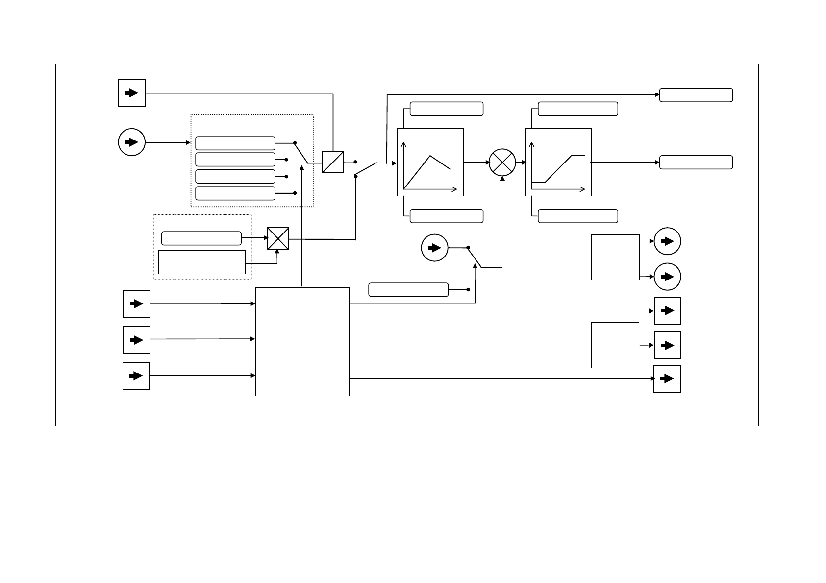
5-6 C h a p t e r 5 : O p e r a t i n g t h e D r i v e
A
A
REVERSE
Digital Input 4
Terminal X15/04
REMOTE SETPOINT
nalog Input 3
Terminal X12/04
Reference Selection
SETPOINT(REMOTE)
JOG SETPOINT
COMMS SETPOINT
0% (stopped)
+
-
Local/
Remote
Ramp
ACCEL TIME
+
+
SPEED SETPOINT
MAX SPEED CLAMP
ClampsReference
SPEED DEMAND
JOG
Digital Input 1
Terminal X15/01
RUN
Digital Input 2
Terminal X15/02
STOP
Digital Input 3
Terminal X15/03
Keypad
LOCAL SETPOINT
FORWARD/REVERSE
Key on Keypad
DECEL TIME
+
-
Sequencing Logic
SPEED TRIM
nalog Input 4
Terminal X12/03
Selectable in Local Mode
Omitted in Jog Mode
0% (stopped)
Figure 3.3 Portion of the Shipping Configuration
MIN SPEED CLAMP
Feedbacks
Speed
Zero
SPEED FBK %
Analog Output 1
Terminal X12/06
TORQUE FEEDBACK
Analog Output 2
Terminal X12/07
RUNNING
Digital Output 1
Terminal X15/08
ZERO SPEED
Digital Output 2
Terminal X15/09
HEALTH
Digital Output 3A & B
Terminal X14/01
Terminal X14/02
AC890PX AC Drive
Page 81

C h a p t e r 5 : O p e r a t i n g t h e D r i v e 5-7
Start/Stop Controlled Locally
The reference value is set by the SETPOINT (LOCAL) parameter. (The direction of rotation is controlled by the DIR key
(forward/reverse) on the 6901 Keypad). When the RUN key is pressed, the SPEED DEMAND ramps up to the reference
value at a rate controlled by ACCEL TIME. The drive will continue to run at the reference value even when the RUN key is
released. Press the STOP key to “stop” the drive.
When the JOG key is pressed and held, the SPEED DEMAND ramps up to the JOG SETPOINT at a ramp rate set by JOG
ACCEL TIME (not shown in the diagram). Release the JOG key to “stop” the drive.
Interaction between RUN and JOG
Only one of these signals can be in effect at any one time; the other signal is ignored. The drive must be “stopped” to change
from running to jogging, or vice versa.
Start/Stop Mode Diagnostics
In the configuration shown, Start/Stop mode provides two DIGITAL OUTPUT signals (RUNNING and HEALTH).
The RUNNING signal is TRUE from the time a start command is processed until a stop sequence is completed. This
normally means the time between the drive starting until the power stack is quenched. Refer to Appendix B : “Sequencing
Logic” for a more detailed description.
AC890PX AC Drive
The HEALTH output is TRUE when the drive is not tripped.
Additional diagnostic parameters are available when using the Keypad. Refer to Chapter 7: "Keypad Menus".
Page 82

5-8 C h a p t e r 5 : O p e r a t i n g t h e D r i v e
Starting and Stopping Methods
NOTE Refer to Appendix D: “Programming” - REFERENCE, SEQUENCING LOGIC, REFERENCE STOP and
REFERENCE RAMP, for explanations of parameters.
Normal Stopping Methods
The Shipping Configuration is set to “Ramp to Stop” (at STOP TIME, set to 10.0s).
• To “stop” the locally controlled drive press the STOP key on the Keypad
• To “stop” the remotely controlled drive remove the 24V from the RUN input (terminal X15/02), and from the STOP input
(terminal X15/03)
Using the Keypad or DSE Configuration Tool, the drive can be selected to “Ramp to Stop”, or to “Coast to Stop” at one of
two rates (STOP TIME or FAST STOP TIME). To do this, change the RUN STOP MODE parameter (PREF102.01) to the
required selection.
Ramp to Stop
Set the SETUP::SEQ & REF::REFERENCE STOP::RUN STOP MODE parameter to RUN RAMP.
When a stop command is received, the drive decelerates from its actual speed towards zero for the programmed DECEL
TIME time. When this time has elapsed, SPEED TRIM is ramped to 0% in the programmed STOP TIME time.
NOTE If SPEED TRIM does not operate, SPEED DEMAND is reduced to 0% in DECEL TIME.
The power stack remains energised until the STOP DELAY period has elapsed.
AC890PX AC Drive
Page 83
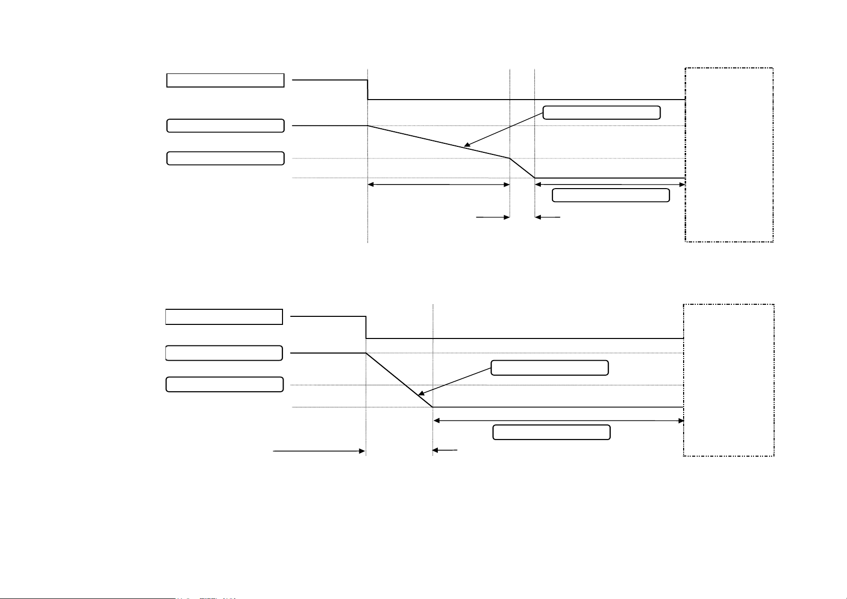
RUN input
REMOTE SETPOINT
SPEED TRIM
Speed 0%
RUN input
C h a p t e r 5 : O p e r a t i n g t h e D r i v e 5-9
SPEED DEMAND
Ramp to zero speed at
DECEL TIME
Ramp SPEED TRIM to
zero at STOP TIME
STOP DELAY
Figure 3.4 Ramp to Stop with a Remote Reference
POW ER
CIRCUIT
DISABLED
AC890PX AC Drive
REMOTE SETPOINT
SPEED DEMAND
SPEED TRIM
Speed 0%
POWER
CIRCUIT
DISABLED
Ramp SPEED DEMAND
STOP DELAY
to zero at STOP TIME
Figure 3.5 Remote to Stop with a Remote Reference: DECEL TIME = 0.0s
A special case exists when the DECEL TIME is set to 0.0 seconds, or when the HOLD parameter is TRUE. In both these
situations the SPEED DEMAND will ramp down to zero at the STOP TIME.
Page 84
5-10 C h a p t e r 5 : O p e r a t i n g t h e D r i v e
R
Coast to Stop
Set the SETUP::SEQ & REF::REFERENCE STOP::RUN STOP MODE parameter to COAST.
In this mode the DECEL TIME ramp and the STOP TIME ramp are both ignored. Thus the SPEED DEMAND changes
immediately to 0% as soon as the Stop command is given. The power stack is also immediately disabled at this time, causing
the load to coast.
RUN input
EMOTE SETPOINT
Speed 0%
POWER CIRCUIT DISABLED
SPEED DEMAND
Figure 3.6 Coast to Stop with a Remote Reference
AC890PX AC Drive
Page 85
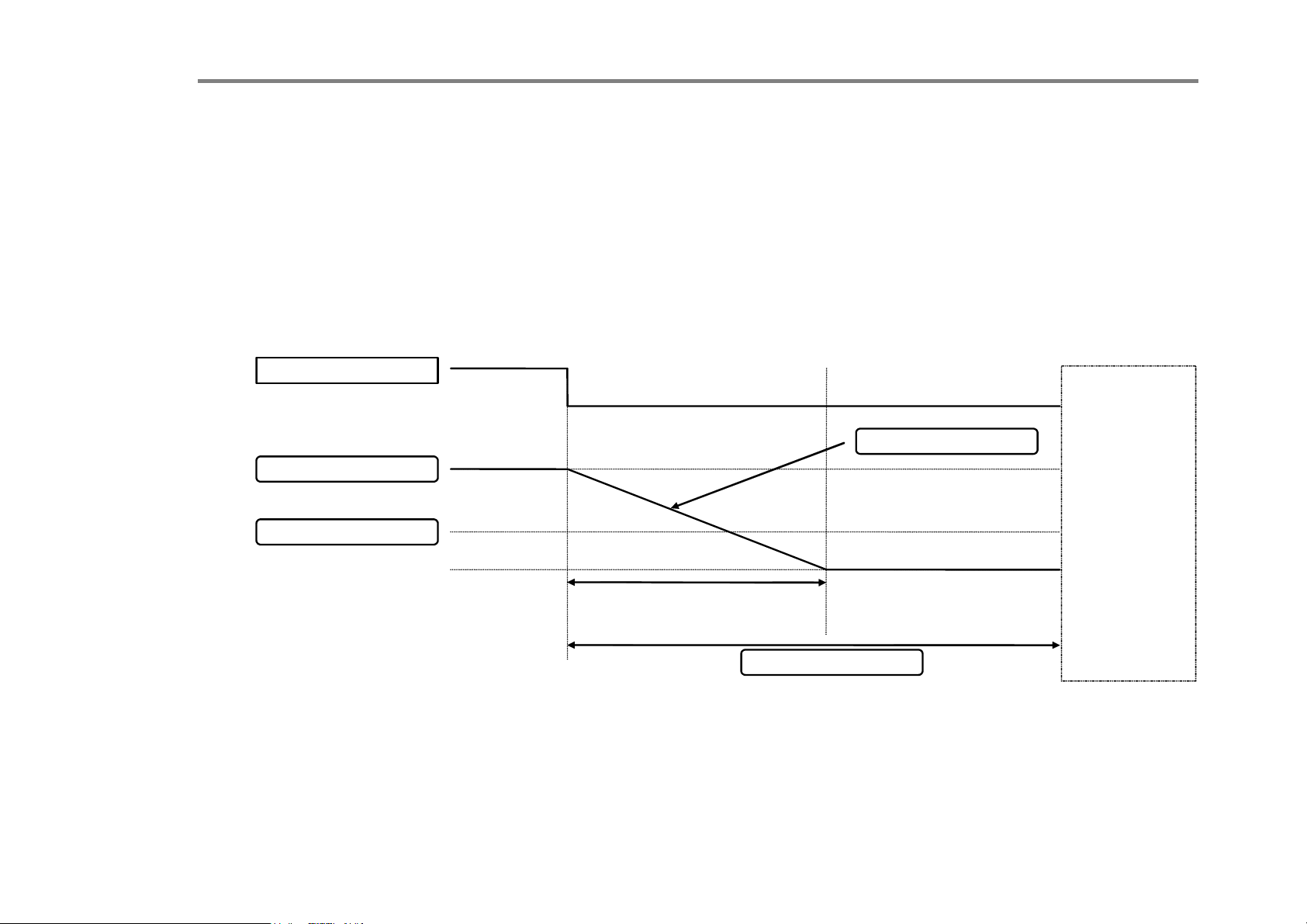
C h a p t e r 5 : O p e r a t i n g t h e D r i v e 5-11
S
R
Advanced Stopping Methods
The drive can be selected to NOT FAST STOP or to NOT COAST STOP. The stopping procedure is unaffected by Local or
Remote Sequencing options.
Forced Fast Stop
The Not Fast Stop mode overrides the RUN FORWARD, RUN REVERSE and JOG inputs in Remote mode, and the RUN
and JOG Keypad keys in Local mode.
Select the SETUP::SEQ & REF::REFERENCE STOP::FAST STOP MODE parameter to either RAMP or COAST. The
stopping sequence starts when the NOT FAST STOP input goes FALSE, regardless of the state of the RUN input.
NOT FAST STOP
EMOTE SETPOINT
SPEED TRIM
Speed 0%
PEED DEMAND
POWER
CIRCUIT
DISABLED
Ramp SPEED DEMAND to
zero at FAST STOP TIME
FAST STOP LIMIT
Figure 3.7 Forced Fast Stop RAMP Mode example
AC890PX AC Drive
Page 86
5-12 C h a p t e r 5 : O p e r a t i n g t h e D r i v e
Forced Coast Stop
Using the Not Coast Stop mode immediately disables the power stack, causing the load to coast to a stop.
The drive gives priority to the NOT COAST STOP signal. The NOT FAST STOP signal is therefore ignored while NOT
COAST STOP is active.
NOT COAST STOP
REMOTE SETPOINT
SPEED TRIM
Speed 0%
POWER CIRCUIT DISABLED
SPEED DEMAND
Figure 3.8 Forced Coast Stop example
AC890PX AC Drive
Page 87
C h a p t e r 5 : O p e r a t i n g t h e D r i v e 5-13
g
g
The Trip Condition
When a trip condition is detected, a similar stopping method to NOT COAST STOP is used. The power stack cannot be reenabled until the trip condition has been cleared and successfully reset.
Refer to Chapter 8: “Trips and Fault Finding” for further details.
Logic Stopping
The drive can be stopped by setting the NOT STOP to FALSE for a short time, (>100 ms). The stop sequence continues even
if the NOT STOP signal goes inactive before the drive is stopped. Various combinations of stop logic are shown below.
RUN FORWARD ignored
as already running
RUN FORWARD
RUN REVERSE
NOT STOP
REMOTE SETPOINT
Speed 0%
REMOTE SETPOINT
Figure 3.9 Interaction between RUN FORWARD, RUN REVERSE and NOT STOP Parameters
RUN FORWARD not
ignored as now stopping
RUN FORWARD not
nored as now stoppin
i
SPEED DEMAND
AC890PX AC Drive
Page 88
5-14 C h a p t e r 5 : O p e r a t i n g t h e D r i v e
JOG ignored as
already running
JOG
RUN FORWARD
NOT STOP
REMOTE SETPOINT
JOG SETPOINT
JOG not ignored as now
stopping. Waits for stop to
complete before acting on
JOG
.
JOG immediately effective
as now stopping from Jog
Speed 0%
SPEED DEMAND
Figure 3.10 Example of the Interaction between RUN FORWARD and JOG Parameters
AC890PX AC Drive
Page 89
Starting Methods
The methods below can be used when the drive has the following default configurations from DSE 890 installed: Closed
Loop Vector, Sensorless Vector, Shaftless Printing, Shipping, Volts/Hertz.
C h a p t e r 5 : O p e r a t i n g t h e D r i v e 5-15
IMPORTANT
DRIVE ENABLE must be True in all cases.
Single Wire Logic Starting
Use just DIGITAL INPUT 2 when the motor direction will always be the same. The motor will run while the RUN switch is
closed, and will stop when it is open.
Note that the SETUP::SEQ & REF::SEQUENCING LOGIC::NOT STOP parameter is active (FALSE - not wired to),
meaning that the drive will only run while the RUN parameter is held TRUE.
24V
FALSE
RUN
Digital Input 2
FALSE
TRUE
TRUE
TRUE
TRUE
FALSE
Sequencing Logic
JOG
RUN FORWARD
NOT STOP
CONTACTOR CLOSED
DRIVE ENABLE
NOT FAST STOP
NOT COAST STOP
REMOTE REVERSE
AC890PX AC Drive
FALSE
TRUE
FALSE
REM TRIP RESET
TRIP RST BY RUN
POWER UP START
Figure 3.11 Wiring for Single Wire Starting (Default Configurations)
Page 90
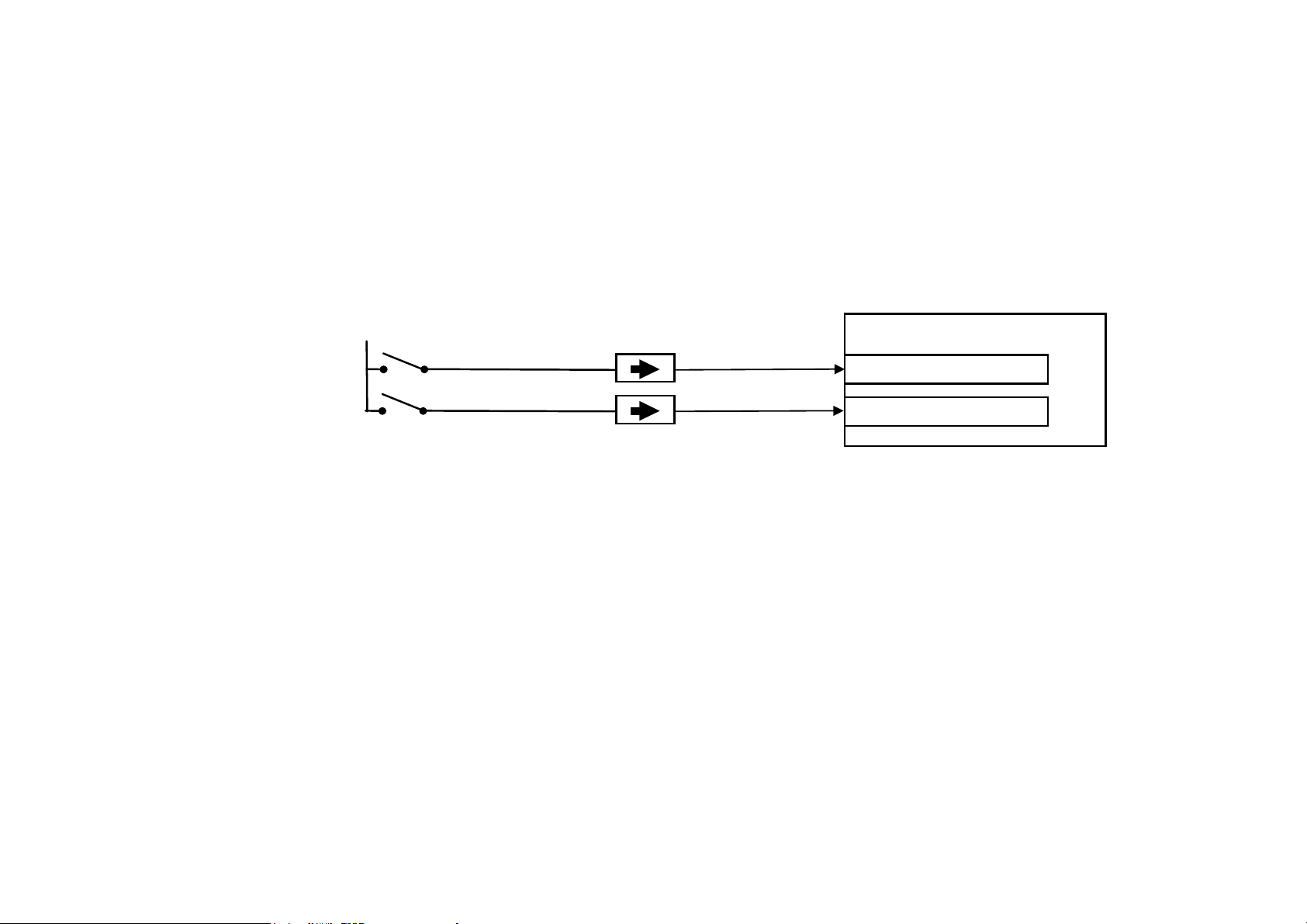
5-16 C h a p t e r 5 : O p e r a t i n g t h e D r i v e
Two Wire Logic Starting
Re-configure the DSE 890 default configuration(s) by connecting SETUP::SEQ & REF::SEQUENCING LOGIC::REMOTE
REV OUT to SETUP::SEQ & REF::REFERENCE::REMOTE REVERSE.
This uses two inputs; RUN and REVERSE. The drive can operate in forward and reverse depending upon which switch is
closed. If both RUN and REVERSE are TRUE (24V) at the same time, both are ignored and the drive will stop.
Note that the SETUP::SEQ & REF::SEQUENCING LOGIC::NOT STOP parameter is active (FALSE - not wired to),
meaning that the drive will only run while the RUN parameter is held TRUE.
24V
RUN
Digital Input 2
REVERSE
Digital Input 4
Sequencing Logic
RUN FORWARD
RUN REVERSE
Figure 3.12 Wiring for Two Wire Logic Starting (Re-configured Default Configurations)
AC890PX AC Drive
Page 91
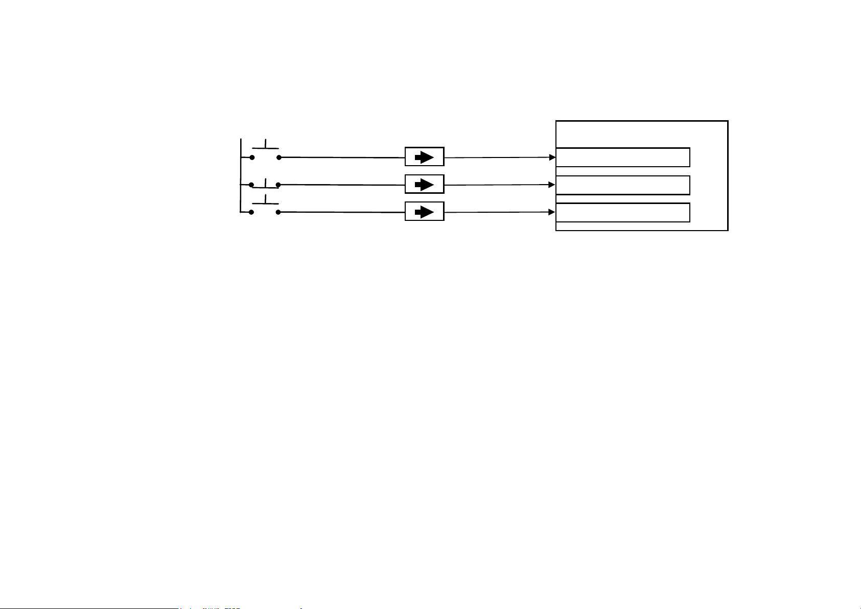
C h a p t e r 5 : O p e r a t i n g t h e D r i v e 5-17
Three Wire Logic Starting
Re-configure the DSE 890 default configuration(s) by connecting SETUP::SEQ & REF::SEQUENCING LOGIC::REMOTE
REV OUT to SETUP::SEQ & REF::REFERENCE::REMOTE REVERSE.
24V
RUN
Digital Input 2
STOP
Digital Input 3
REVERSE
Digital Input 4
Sequencing Logic
RUN FORWARD
NOT STOP
RUN REVERSE
Figure 3.13 Wiring for Three Wire Logic Starting (Re-configured Default Configurations)
• Fit normally-open push button switches to RUN FORWARD and RUN REVERSE.
• Fit a normally-closed push button switch to NOT STOP, thus NOT STOP is held TRUE (24V). When TRUE, the action of
NOT STOP is to latch the RUN FORWARD and RUN REVERSE signals. When FALSE, these signals are not latched.
For example, operating the RUN FORWARD switch starts the drive running forward. Operating the RUN REVERSE switch
causes the drive to run in reverse. Operating the NOT STOP switch (making “NOT STOP” FALSE) at any time causes the
drive to stop running.
NOTE The JOG parameter is never latched in this way. The drive only jogs while the JOG parameter is TRUE.
Starting Several Drives Simultaneously
IMPORTANT
AC890PX AC Drive
We do not recommend that the DRIVE ENABLE signal is used to start a drive in “normal” use.
Use the DRIVE ENABLE parameter to control the output power stack. When this parameter is FALSE, the power stack is
disabled regardless of the state of any other parameters. In conjunction with the HEALTH output parameter, DRIVE
ENABLE can synchronise several drives on power-up.
Page 92

5-18 C h a p t e r 5 : O p e r a t i n g t h e D r i v e
Application Advice
• Application advice is available through our Technical Support Department, who can also arrange for on-site assistance
if required. Refer to the back cover of this manual for the address of your local Parker SSD Drives company.
• Always use gold flash relays, or others designed for low current operation (5mA), on all control wiring.
• Remove all power factor correction equipment from the motor side of the drive before use.
• Avoid using motors with low efficiency and small cos ø (power factor) as they require a larger kVA rated drive to
produce the correct shaft kW.
Brake Motors
Brake motors are used in applications requiring a mechanical brake for safety or other operational reasons. The motor can be
a standard induction motor fitted with an electro-mechanical brake, or it could be a special conical rotor machine. In the case
of a conical rotor machine the spring-loaded brake is controlled by the motor terminal voltage as follows:
At rest the motor is braked.
When the motor is energised an axial component of the magnetic field due to the conical air-gap overcomes the force of the
brake spring and draws the rotor into the stator. This axial displacement releases the brake and allows the motor to accelerate
like a normal induction motor.
When the motor is de-energised the magnetic field collapses and the brake spring displaces the rotor, pushing the brake disc
against the braking surface.
Drives can be used to control the speed of conical rotor brake motors since the linear V/F characteristic maintains the motor
magnetic field constant over the speed range. It will be necessary to set the FIXED BOOST parameter to overcome motor
losses at low speed (see the FLUXING menu on the Keypad).
Using Output Contactors
The use of output contactors is permitted. It is recommended that this type of operation be limited to emergency use only or in
a system where the drive can be inhibited before closing or opening this contactor.
AC890PX AC Drive
Page 93
C h a p t e r 5 : O p e r a t i n g t h e D r i v e 5-19
Using Motor Chokes (output)
Motor chokes may be used with the 380V/460V and 500V/575V AC890PX AC Drive.
Installations with long cable runs may suffer from nuisance overcurrent trips. A choke may be fitted in the drive output to
limit capacitive current. Screened cable has a higher capacitance and may cause problems in shorter runs. A choke may be
used on cable lengths of over 100m.
Motor Choke
Maximum Operating Current
250A CO471702U250
320A CO471702U320
400A CO471702U400
500A CO471702U500
600A CO471702U600
750A CO471702U750
Contact Parker SSD Drives for recommended choke values.
Parker SSD Drives Part Number
AC890PX AC Drive
Page 94
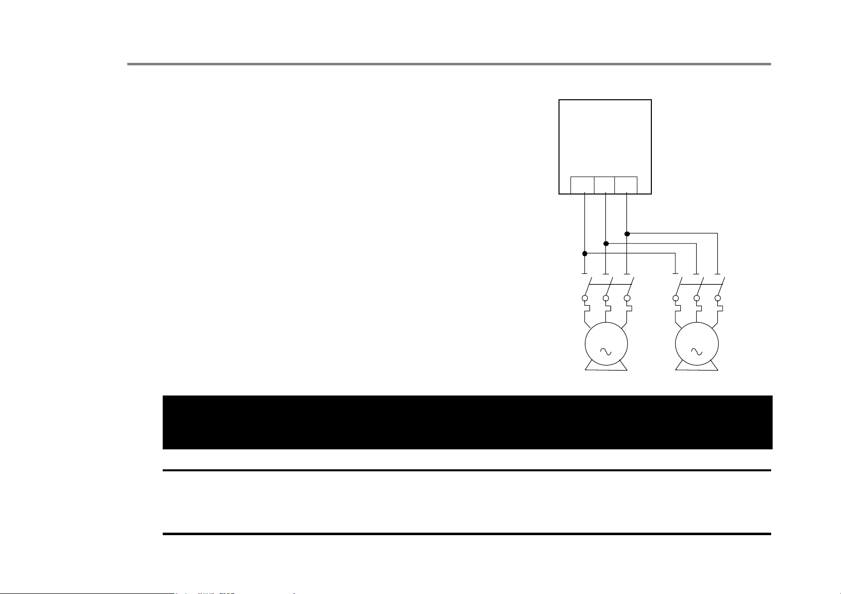
5-20 C h a p t e r 5 : O p e r a t i n g t h e D r i v e
Using Multiple Motors on a Single Drive
A single large drive can be used to supply several smaller motors provided that
each individual motor has overload protection.
NOTE Conventional V/F control strategy must be enabled for use with parallel
motors. (Sensorless vector control strategy cannot be used). See the
VECTOR ENABLE parameter under VECTOR SET-UP menu at level 2.
VSD
The drive must be rated to supply the total motor current. It is not sufficient
to simply sum the power ratings of the motors, since the drive has also to
supply the magnetising current for each motor.
Note that the overload device will not prevent the motor overheating due to
inadequate cooling at low speed. Force vented motors may be required; consult
your motor supplier.
Figure 3.14 Single Drives supplying Multiple Motors
WARNING
All motors should be connected to the drive output before the START command is given.
M1/U M2/V
M3/W
OL1 OL2
M1 M2
Caution
Restrict the total cable length on multiple motor installations as follows:
50 metres with no output choke fitted, 300 metres with choke.
AC890PX AC Drive
Page 95

C h a p t e r 5 : O p e r a t i n g t h e D r i v e 5-21
High Starting Torque
Applications requiring high motor starting torque (greater than 100% of rated torque) need careful setup of the drive voltage
boost feature. Gradually increase the FIXED BOOST parameter in 1% steps until the drive generates sufficient starting
torque.
It is important to use the minimum level of FIXED BOOST necessary to accelerate the load. Using a level of FIXED BOOST
higher than necessary will lead to increased motor heating and increased risk of drive overload.
Setting the FIXED BOOST parameter level too high can also cause the drive current limit feature to operate. If this occurs,
the drive will be unable to ramp up in frequency. The IT LIMITING diagnostic (INVERSE TIME function block) will
indicate TRUE when the inverse time current limit feature is operating. Simply reducing the level of the FIXED BOOST
parameter will remove this problem.
NOTE Motor torques greater than 100% require high currents to be drawn from the drive. Thus, the CURRENT LIMIT
parameter (CURRENT LIMIT function block) will have to be set accordingly such that the drive current limit feature
will not activate when accelerating the load.
The best motor starting performance can be achieved by setting up the SLIP COMP function block, refer to the Appendix D:
“Programming” - SLIP COMP. Also setting the BASE VOLTS parameter (VOLTAGE CONTROL function block) to
115.4% and the FREQ SELECT parameter (PATTERN GEN function block) to 3kHz, can help to start difficult loads in the
most extreme cases.
AC890PX AC Drive
Page 96

5-22 C h a p t e r 5 : O p e r a t i n g t h e D r i v e
AC890PX AC Drive
Page 97

C h a p t e r 6 : T h e K e y p a d 6-1
C h a p t e r
T h e K e y p a d
In this chapter, learn about the control keys and keypad indications. The main menu
6
maps are shown here. For details of sub-menus refer to Chapter 7.
AC890PX AC Drive
Page 98
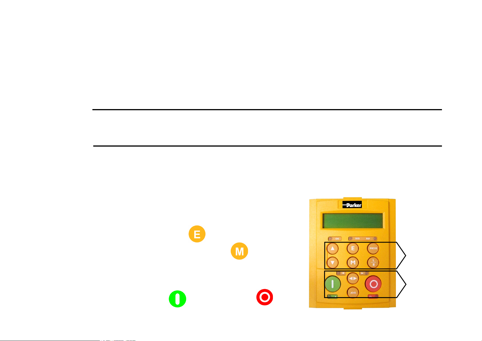
6-2 C h a p t e r 6 : T h e K e y p a d
6901 Keypad
The 6901 Keypad is a plug-in MMI (Man-Machine Interface) option that provides local control of the drive, monitoring, and
complete access for application programming. It can be used with a wide range of Parker SSD Drives' products including the
590+, 605, 650V (Frames C-F), 650 (Frames 1-3 if fitted with a RS232 port), 690+ and 890 drives.
The 6901 Keypad can be mounted up to 3 metres away from the 890 using the optional panel mounting kit with connecting
lead: refer to "Remote Mounting the Keypad", page 6-23.
At any time, there may be a loss of motor control and as such separate/independent application measures should be taken to
The keypad displays the OPERATOR, DIAGNOSTICS, QUICK SETUP, SETUP & SYSTEM menus (SETUP menu lists all
parameters available in the DSE 890 Configuration Tool)
Initial Power-Up Conditions
The Keypad will display the Operator menu.
Caution
ensure that such loss of motor control cannot present a safety hazard.
To display the Software Version:
Press and hold
Time-out or press .
To Start in
Local Mode:
Press
to display software version.
To Stop in
Local Mode:
Press
Programming
Keys
Local
Control
Keys
AC890PX AC Drive
Page 99
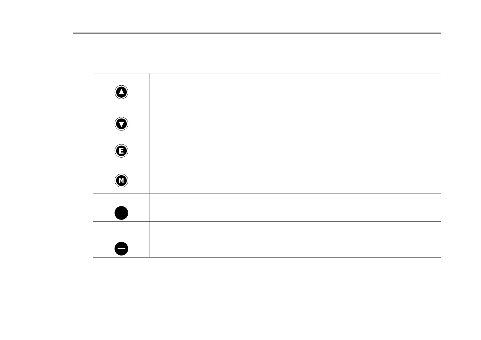
Control Key Definitions
Keys for Programming the Drive
C h a p t e r 6 : T h e K e y p a d 6-3
UP
DOWN
ESCAPE
MENU
PROG
PROG
LOCAL/
REMOTE
L
R
Navigation
Parameter
Command Acknowledge
Navigatio
Parameter
Navigation
Parameter
Trip Message
Navigation
Parameter
the left of the bottom line). Hold to display the PREF.
Navigation
menu.
Control
Control (Ref). When toggling, the display automatically goes to the relevant SETPOINT screen,
and the SETPOINT (LOCAL) screen will have the and keys enabled to alter the setpoint.
- Moves upwards through the list of parameters or menus
- Increments the value of the displayed parameter.
- Confirms action when in a command menu.
n - Moves downwards through the list of parameters or menus
- Decrements the value of the displayed parameter.
- Displays the previous level’s Menu.
- Returns to the parameter list.
- Clear the Trip or Error message from the display.
- Displays the next Menu level, or the first parameter of the current Menu.
- Allows a writable parameter to be modified (this is indicated by → appearing on
- Toggles between current locations within the Operator menu and any other
- Toggles between Remote and Local Mode for both Start/Stop (Seq) and Speed
AC890PX AC Drive
Page 100
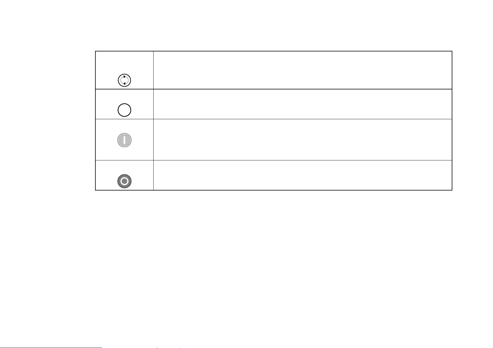
6-4 C h a p t e r 6 : T h e K e y p a d
Keys for Operating the Drive Locally
FORWARD/
REVERSE
JOG
JOG
RUN
STOP/RESET
Control
Speed Control mode.
Control
key is released, the drive returns to “stopped”. Only operates when the drive is “stopped“ and
in Local Start/Stop mode.
Control
SETPOINT parameter.
Trip Reset
is in Local Start/Stop (Seq) mode.
Control
Trip Reset
- Changes the direction of motor rotation. Only operates when the drive is in Local
- Runs the motor at a speed determined by the JOG SETPOINT parameter. When the
- Runs the motor at a speed determined by the LOCAL SETPOINT or REMOTE
- Resets any trips and then runs the motor as above. Only operates when the drive
- Stops the motor. Only operates when the drive is in Local Sequence mode.
- Resets any trips and clears displayed message if trip is no longer active.
The L/R Key
The L/R key (LOCAL/REMOTE) toggles between Remote and Local Mode. In doing so, the view of the SETPOINT
parameter in the OPERATOR menu toggles between SETPOINT (LOCAL) and SETPOINT (REMOTE). The default is for
the SETPOINT (REMOTE) parameter to be displayed.
NOTE A different naming convention is applied in the OPERATOR menu for these parameters when displayed as the first
parameter entry:
• REMOTE SETPOINT is displayed as SETPOINT (REMOTE)
• LOCAL SETPOINT is displayed as SETPOINT (LOCAL)
• COMMS SETPOINT is displayed as SETPOINT (COMMS)
• JOG SETPOINT is displayed as SETPOINT (JOG)
AC890PX AC Drive
 Loading...