

Page 1
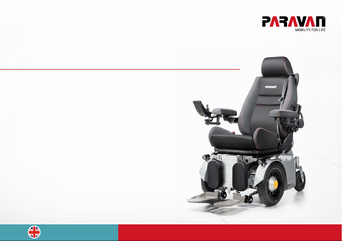
The Paravan wheelchair series
User manual
PR 50
EN V3.0
www.paravan.com
Page 2

Publisher and Copyright Holder: PARAVAN GmbH, 72539 Pfronstetten-Aichelau
Date of publication: 1.10.2017
Document: PR_Benutzerhandbuch_V3.0_EN
Page 3

Dear customer,
Thank you very much for having chosen our PR series PARAVAN electric wheelchair.
You will nd all the important information and tips you need on your new electric wheelchair in this User's
Manual. Please carefully read the information on the pages to follow in order to make sure your electric
wheel chair will give you many years of problem-free service. Keep this User's Manual in a handy place
for later reference. Our user manual contains answers to questions relating to the operation and care of
the electric wheelchair and its ttings. It you should have any questions or suggestions on the wheelchair,
please do not hesitate to get in contact with us.
Your PARAVAN team
3
Page 4

Table of contents
General
1. Details on publisher ............................................................................................. 15
1.1 Your manufacturer ................................................................................................................... 15
1.1.1 Copyright .................................................................................................................................. 16
1.1.2 Technical status of this documentation ................................................................................. 16
2. On this User's Manual ..........................................................................................17
2.1 Disclaimer ................................................................................................................................ 18
2.1.1 Guarantee ................................................................................................................................. 19
2.1.2 Technical alterations ............................................................................................................... 20
2.2 Target groups ........................................................................................................................... 22
2.3 Explanation of symbols ........................................................................................................... 23
2.3.1 Structure of safety notices ...................................................................................................... 24
3. Safety note .......................................................................................................... 25
3.1 General safety notes ................................................................................................................ 25
3.1.1 Notes on usage ........................................................................................................................ 25
3.1.2 Notes on usage ........................................................................................................................ 29
3.1.3 Notes on transport ................................................................................................................... 30
4. Functional description ......................................................................................... 31
4.1 Manufacturing standard .......................................................................................................... 31
4.2 Appropriate usage ................................................................................................................... 32
4.2.1 Usage of the electric wheelchair............................................................................................. 33
4.3 Approvals, certications .......................................................................................................... 34
4.3.1 EU approval as a driver seat .................................................................................................... 34
4.3.2 Clearance certication as hazardous cargo (accumulator).................................................. 35
4.3.3 German Ordinance on Assistive Technology (HMV No.) ...................................................... 36
4.3.4 Denition of assistive technology (excerpt) .......................................................................... 36
4
Table of contents
Page 5

Information
5. Details relating to the product..............................................................................37
5.1 Trademark and type labelling (ratings plate) ......................................................................... 37
5.2 Position of the type label (ratings plate) ................................................................................ 38
5.3 Details on your electric wheelchair ......................................................................................... 39
5.3.1 Your wheelchair's ratings plate ............................................................................................... 39
5.4 Accessories .............................................................................................................................. 40
5.4.1 Accessories included .............................................................................................................. 40
5.4.2 Accessories deliverable........................................................................................................... 40
6. Description/Functioning or your electric wheelchair ............................................41
6.1 The specially developed orthopaedic seat ............................................................................. 41
6.2 Joystick control ........................................................................................................................ 42
6.3 Special controls ....................................................................................................................... 42
6.4 Lift and tilt (seat inclination) ................................................................................................... 43
6.5 Vibration-damped foot rests ................................................................................................... 43
6.6 Safe for trafc conditions according to German trafc law .................................................. 44
6.6.1 Section 24 Special means of transport .................................................................................. 44
7. Overview of the PARAVAN electric wheelchair .....................................................45
7.1 Denition of vocabulary for parts and their positions ........................................................... 45
7.2 Denition of vocabulary for parts, place of installation, chassis .......................................... 46
Prepare
8. Handing over the electric wheelchair ................................................................... 48
8.1 Receiving your new electric wheelchair ................................................................................. 48
8.2 How your electric wheelchair is delivered to you ................................................................... 48
8.3 Tools included with the delivery .............................................................................................. 49
Table of contents
5
Page 6

9. Settings on your electric wheelchair; electronic ................................................... 50
10. Settings on your electric wheelchair; mechanical ................................................51
10.1 Receiving your new electric wheelchair ................................................................................. 51
10.2 The armrest cushion ................................................................................................................ 52
10.2.1 Setting the armrest cushion .................................................................................................... 52
10.2.2 Setting the horizontal position of the armrest cushion ......................................................... 53
10.3 The armrest .............................................................................................................................. 54
10.4 Set the height of the armrest .................................................................................................. 55
10.5 Set the angle of the armrest .................................................................................................... 57
10.6 Set the projection of the armrest ............................................................................................ 58
10.7 Setting the movability of the control panel ............................................................................ 59
10.8 The foot support unit ............................................................................................................... 60
10.8.1 Setting the lower leg length ..................................................................................................... 60
10.8.2 Setting the tibialis angle .......................................................................................................... 61
10.8.3 Setting the foot rest angle ....................................................................................................... 62
11. Use of the special orthopaedic seat ..................................................................... 63
11.1 Setting the back support ......................................................................................................... 63
11.1.1 Setting the back support angle ............................................................................................... 63
11.1.2 Setting the side bolsters (thoracic supports) ........................................................................ 64
11.2 Setting the lumbar support ..................................................................................................... 65
11.2.1 Setting the head support ......................................................................................................... 66
11.2.2 Setting your sitting position .................................................................................................... 67
11.3 Setting your lying position ....................................................................................................... 68
11.4 Setting the standing up position ............................................................................................. 69
6
Table of contents
Page 7

Operate
12. Removing and reattaching the chassis cladding ..................................................70
12.1 Removing and reattaching the rear cladding ......................................................................... 70
12.2 Removing and reattaching the side cladding ......................................................................... 71
13. Driving your electric wheelchair ...........................................................................72
13.1 Insurance, civil liability insurance ........................................................................................... 72
13.2 Functional checking before driving......................................................................................... 73
13.3 Buckling the safety belt ........................................................................................................... 74
13.4 Controlling the electric wheelchair's travel direction ............................................................. 75
13.5 Driving a curve.......................................................................................................................... 76
13.6 Braking your electric wheelchair ............................................................................................. 77
13.6.1 Braking systems on your electric wheelchair ........................................................................ 77
13.7 Braking the electric wheelchair ............................................................................................... 78
13.8 Travelling on hills, uphill and downhill travel .......................................................................... 79
13.9 The driving programmes / drive levels ................................................................................... 80
13.10 Driving manually, manual operation ....................................................................................... 81
13.10.1 Use of the brake release lever (emergency release) ............................................................. 81
13.11 Terrain requirements, surfaces ............................................................................................... 82
13.11.1 Ability to ford, or drive through water ..................................................................................... 82
13.11.2 Climbing and overtaking capacity .......................................................................................... 83
13.11.3 Load-bearing capacity ............................................................................................................. 83
13.11.4 Impassible surfaces or areas .................................................................................................. 83
13.11.5 Slippery surfaces, traction ....................................................................................................... 83
14. Parking and storing your electric wheelchair .......................................................84
14.1 Immobiliser/key function ........................................................................................................ 84
Table of contents
7
Page 8

15. Loading and transporting your electric wheelchair ............................................... 85
15.1 Rules when loading wheelchairs............................................................................................. 85
15.2 Securing your electric wheelchair, lashing ............................................................................. 86
16. Controls ..............................................................................................................87
16.1 Control panel R-NET CJSM2 ................................................................................................... 87
16.1.1 Overview of the control elements ........................................................................................... 87
16.1.2 Status display ........................................................................................................................... 88
16.1.3 Start, switch off ........................................................................................................................ 89
16.1.4 Switch direction indicator on and off ..................................................................................... 90
16.1.5 Switch light on and off ............................................................................................................. 90
16.1.6 Switch hazard lights on and off .............................................................................................. 91
16.1.7 Driving functions overview ...................................................................................................... 92
16.1.8 Select drive program, drive ...................................................................................................... 93
16.1.9 Electrical seat adjustment ....................................................................................................... 94
16.1.10 Set time/date ........................................................................................................................... 95
16.1.11 Show/hide clock, congure 12h/24h display ......................................................................... 96
16.1.12 Adjust display brightness ........................................................................................................ 97
16.1.13 Adjust display brightness, automatic ..................................................................................... 97
16.1.14 Block the controls (with the wheelchair switched on) .......................................................... 98
16.1.15 Release the controls (with the wheelchair switched off) ...................................................... 98
16.2 Control panel R-NET CJSM-L .................................................................................................. 99
16.2.1 Overview of the control elements ........................................................................................... 99
16.2.2 Status display ........................................................................................................................... 100
16.2.3 Start and switch off ................................................................................................................. 101
16.2.4 Switch direction indicator on and off ..................................................................................... 102
16.2.5 Switch light on and off ............................................................................................................. 102
16.2.6 Switch hazard lights on and off .............................................................................................. 103
16.2.7 Driving functions overview ...................................................................................................... 104
8
Table of contents
Page 9

16.2.8 Select drive program, drive ...................................................................................................... 105
16.2.9 Electrical seat adjustment ....................................................................................................... 106
16.2.10 Set time/date ........................................................................................................................... 107
16.2.11 Show/hide clock, congure 12h/24h display ......................................................................... 108
16.2.12 Adjust display brightness ....................................................................................................... 109
16.2.13 Adjust the display background and brightness ..................................................................... 109
16.2.14 Block the controls (with the wheelchair switched on) .......................................................... 110
16.2.15 Release the controls (with the wheelchair switched off) ...................................................... 110
Help
17. Getting out of your electric wheelchair ................................................................111
17.1 Procedure when getting out from the side ............................................................................. 112
18. Care and maintenance .........................................................................................113
18.1 Service partners ....................................................................................................................... 113
18.2 Cleaning and care .................................................................................................................... 114
19. Disposal and environmental protection ................................................................115
19.1 Packaging materials ................................................................................................................ 116
19.2 Re-commissioning ................................................................................................................... 117
19.3 Notes on transfer ..................................................................................................................... 118
20. Correcting failures...............................................................................................119
20.1 Flashing codes indicating the status of the control panel .................................................... 119
Table of contents
9
Page 10

Technology
21. Electrical system .................................................................................................121
21.1 Automatic safety switches ...................................................................................................... 121
21.2 The main safety switch ........................................................................................................... 122
21.2.1 Resetting the main safety switch ........................................................................................... 122
21.3 The secondary safety switch .................................................................................................. 123
21.3.1 Resetting the secondary safety switch .................................................................................. 123
21.4 Overload protection ................................................................................................................. 124
21.4.1 Resetting the overload protection: .......................................................................................... 124
21.5 Facility to connect ancillary devices ....................................................................................... 125
21.6 The lighting system ................................................................................................................. 126
21.7 The maintenance-free accumulators ..................................................................................... 127
21.8 Notes on accumulators ........................................................................................................... 128
21.9 Changing your accumulators .................................................................................................. 129
21.10 Charging your electric wheelchair .......................................................................................... 130
21.10.1 Procedure for charging your electric wheelchair ................................................................... 131
21.10.2 The charging device ................................................................................................................. 132
21.10.3 Positioning the charging device .............................................................................................. 132
22. Technical equipment ........................................................................................... 133
22.1 Technical data and dimensions .............................................................................................. 133
22.2 Replacement parts................................................................................................................... 136
23. Systems and technical documentation ................................................................137
23.1 How to deal with closed accumulators .................................................................................. 137
23.2 Customer service book............................................................................................................ 138
23.3 EU Declaration of Conformity ................................................................................................. 139
23.4 Protocol of the handover brieng ........................................................................................... 140
10
Table of illustrations
Page 11

Table of illustrations
Fig. 1: QR Code .................................................................................................................................... 15
Fig. 2: Direction of travel ..................................................................................................................... 17
Fig. 3: Safety note ............................................................................................................................... 24
Fig. 4: TÜV Logo .................................................................................................................................. 34
Fig. 5: Ratings plate ............................................................................................................................ 37
Fig. 6: Location, ratings plate ............................................................................................................. 38
Fig. 7: Docking station ........................................................................................................................ 40
Fig. 8: Front illumination ..................................................................................................................... 44
Fig. 9: Rear illumination ...................................................................................................................... 44
Fig. 10: Overview of wheelchair ........................................................................................................... 45
Fig. 11: Components, rear of chassis .................................................................................................. 46
Fig. 12: Components, front of chassis ................................................................................................. 47
Fig. 13: Socket wrench .......................................................................................................................... 49
Fig. 14: Allen key ................................................................................................................................... 49
Fig. 15: Angled arm rest cushion ......................................................................................................... 52
Fig. 16: Position of armrest cushion .................................................................................................... 53
Fig. 17: Checking the position of the armrest ..................................................................................... 54
Fig. 18: Height of arm rest .................................................................................................................... 55
Fig. 19: Lever, clamping screw ............................................................................................................. 56
Fig. 20: Armrest angle ........................................................................................................................... 57
Fig. 21: Armrest projections ................................................................................................................. 58
Fig. 22: Swivel mechanism ................................................................................................................... 59
Fig. 23: Lower leg length ....................................................................................................................... 60
Fig. 24: Tibialis angle ............................................................................................................................ 61
Fig. 25: Foot rest angle ......................................................................................................................... 62
Fig. 26: Back support angle .................................................................................................................. 63
Fig. 27: Thoracic supports .................................................................................................................... 64
Fig. 28: Lumbar support, vers. 1 ........................................................................................................... 65
Fig. 29: Lumbar support, vers. 2 ........................................................................................................... 65
Table of illustrations
11
Page 12

Fig. 30: Head support ........................................................................................................................... 66
Fig. 31: Sitting position ......................................................................................................................... 67
Fig. 32: Lying position ........................................................................................................................... 68
Fig. 33: Stand-up position ..................................................................................................................... 69
Fig. 34: Rear cladding ........................................................................................................................... 70
Fig. 35: Rear light and cable ................................................................................................................. 70
Fig. 36: Side cladding ............................................................................................................................ 71
Fig. 37: Front headlight, cable .............................................................................................................. 71
Fig. 38: Brake release lever (emergency release) ............................................................................... 73
Fig. 39: Fastening the seat belt ............................................................................................................ 74
Fig. 40: Belt fastener ............................................................................................................................. 74
Fig. 41: Joystick .................................................................................................................................... 75
Fig. 42: Brake release lever (emergency release) ............................................................................... 81
Fig. 43: Securing point at front ............................................................................................................. 86
Fig. 44: Securing point at rear .............................................................................................................. 86
Fig. 45: Control panel R-NET CJSM2 ................................................................................................... 87
Fig. 46: Function keys ........................................................................................................................... 88
Fig. 47: Status display ........................................................................................................................... 88
Fig. 48: “On / off” key ............................................................................................................................ 89
Fig. 49: Speed control (tortoise) active ............................................................................................... 89
Fig. 51: Light on and off ........................................................................................................................ 90
Fig. 52: Turn signal right / left .............................................................................................................. 90
Fig. 50: Light symbol (colour)............................................................................................................... 90
Fig. 54: Hazard lights on / off ............................................................................................................... 91
Fig. 53: Symbols (colour) ...................................................................................................................... 91
Fig. 55: Driving functions ...................................................................................................................... 92
Fig. 56: Charging status indicator (driving function blocked) ............................................................ 92
Fig. 57: Select drive program ................................................................................................................ 93
Fig. 58: Joystick travelling direction .................................................................................................... 93
12
Table of illustrations
Page 13

Fig. 59: Display of seat functions ......................................................................................................... 94
Fig. 60: “Set time” function menu ........................................................................................................ 95
Fig. 61: Setting the time and date ........................................................................................................ 95
Fig. 62: Set clock to visible/invisible .................................................................................................... 96
Fig. 64: Setting the display brightness ................................................................................................. 97
Fig. 63: Autom. display brightness ...................................................................................................... 97
Fig. 66: Turn signal right / left .............................................................................................................. 98
Fig. 65: Lock symbol ............................................................................................................................. 98
Fig. 67: Control panel R-NET CJSM-L .................................................................................................. 99
Fig. 68: Function keys ........................................................................................................................... 100
Fig. 69: Status display ........................................................................................................................... 100
Fig. 70: “On / off” key ............................................................................................................................ 101
Fig. 71: Speed control (tortoise) active ............................................................................................... 101
Fig. 73: Light on and off ........................................................................................................................ 102
Fig. 74: Turn signal right / left .............................................................................................................. 102
Fig. 72: Light symbol (colour)............................................................................................................... 102
Fig. 76: Hazard lights on / off ............................................................................................................... 103
Fig. 75: Symbols (colour) ...................................................................................................................... 103
Fig. 77: Driving functions ...................................................................................................................... 104
Fig. 78: Driving function blocked .......................................................................................................... 104
Fig. 79: Select drive program ................................................................................................................ 105
Fig. 80: Joystick travelling direction .................................................................................................... 105
Fig. 81: Display of seat functions ......................................................................................................... 106
Fig. 82: “Set time” function menu ........................................................................................................ 107
Fig. 83: Setting the time and date ........................................................................................................ 107
Fig. 84: Set clock to visible/invisible .................................................................................................... 108
Fig. 86: Setting the display brightness ................................................................................................. 109
Fig. 85: Setting the display background .............................................................................................. 109
Fig. 88: Blocking the controls ............................................................................................................... 110
Table of illustrations
13
Page 14

Fig. 87: Controls blocked – block symbol ........................................................................................... 110
Fig. 89: Move, foot rests ....................................................................................................................... 112
Fig. 90: Move, armrest .......................................................................................................................... 112
Fig. 91: Recycling .................................................................................................................................. 116
Fig. 92: Main safety switch, activ ......................................................................................................... 122
Fig. 93: Main safety switch ................................................................................................................... 122
Fig. 94: Sec. safety switch, activ. ......................................................................................................... 123
Fig. 95: Secondary safety switch ......................................................................................................... 123
Fig. 96: Front illumination ..................................................................................................................... 126
Fig. 97: Rear illumination ...................................................................................................................... 126
Fig. 98: Power connection .................................................................................................................... 129
Fig. 99: Retting, accumulator ............................................................................................................. 129
Fig. 100: Plug in the charging cable ....................................................................................................... 131
Fig. 101: Pos. the charging device ......................................................................................................... 132
Fig. 102: EU Declaration of Conformity ................................................................................................. 139
14
Table of illustrations
Page 15

1. Details on publisher
1.1 Your manufacturer
Fig. 1: QR Code
PARAVAN GmbH
Main ofce / HQ/ Production Plant
Paravanstraße 5-10, D-72539 Pfronstetten-Aichelau
› Phone: +49 (0) 73 88 / 99 95-91
› Fax: +49 (0) 73 88 / 99 95-999
› Email: [email protected]
› Internet: www.paravan.com
› Managing Director: Roland Arnold
Many mobile phones and PDAs contain an integrated camera
and software that allows you to interpret QR codes so that you
can read our contact information directly into the address book
of your mobile phone or PDA.
General
InformationPrepareOperateHelpTechnology
Details on publisher
15
Page 16

General
1.1.1 Copyright
This documentation and all its constituent sections are protected by copyright. The rights based on this co-
Information Prepare Operate Help Technology
pyright, in particular those in relation to translation, reprinting, representation, extraction of illustrations and
tables, broadcast, microlming or any other means of reproduction and saving in data processing systems,
even if only excerpts are used, are reserved. Any reproduction of this work or of any parts of this work is only
permitted even in exceptional cases within the limits set by the terms of the copyright law of the Federal Re-
public of Germany of 09 September 1965 in its version currently in force. It will always be liable for payment.
Any infringements will be subject to the penal clauses of that copyright law.
› Copyright © PARAVAN GmbH 2017. All rights reserved!
1.1.2 Technical status of this documentation
All details on technical data and/or specications, illustrations and information in this User's Manual correspond to the status as on close of press in December 2016.
The User's Manual for the PR50 electric wheelchair was written in the German language and may be translated into other languages. In case of any inconsistencies, the German version shall be legally binding.
16
On this User's Manual
Page 17

2. On this User's Manual
This User's Manual does not represent product documentation in the
sense of a set of maintenance and repair instructions, and is thus not
suitable for use in executing maintenance and repair work by its possessor, or for instructing on how to execute such work. You are in receipt
of information on the nature of the electric wheelchair model and on its
use over its entire life cycle from transport (delivery) to decommissioning (taking out of service). Below are listed and described the product's
most important features. All product features mentioned may be combined variously in different models, and functions and may differ from
the standard version.
Fig. 2: Direction of travel
This User's Manual forms an integral part of this electric
wheelchair product and must always be stored in the vicinity
of the electric wheelchair in order to allow you to access the
important information it contains quickly.
General
InformationPrepareOperateHelpTechnology
On this User's Manual
All page and directional indications made in the documentation
are always given from the point of view of the operator in the
direction of travel of the device.
17
Page 18

2.1 Disclaimer
General
Only by observing and putting into practice the knowledge provided by this User's Manual can the electric
Information Prepare Operate Help Technology
wheelchair be guaranteed error and fault free operation. PARAVAN GmbH does not take any responsibility for
or give any guarantee against damages or operational interruptions that may be caused during operation by
the non-observance of the instructions contained in this User's Manual or by any modications made to the
electric wheelchair.
In order to ensure the fault-free operation of your electric wheelchair, please observe the maintenance instructions and intervals.
See Section "18 Care and maintenance"
18
On this User's Manual
Page 19

2.1.1 Guarantee
Guarantee cover is dened exclusively by the relevant provisions set by PARAVAN.
Expressly excluded from guarantee entitlements is any damage resulting from:
General
› Wear and tear
› Inappropriate operation or usage; e.g. overloading
› Incorrect/Irregular maintenance
› Incorrect/Irregular care
See your personal "Guarantee card"
On this User's Manual
InformationPrepareOperateHelpTechnology
19
Page 20

General
2.1.2 Technical alterations
Any modications made to the safety equipment and technical changes to the electric wheelchair, however
Information Prepare Operate Help Technology
small, are absolutely prohibited. All alterations must be executed by PARAVAN GmbH.
PARAVAN GmbH reserves the right to make technical alterations and improvements to the product in the
interests of four customers and due to advancing technology.
Any modication not approved by PARAVAN GmbH made to the electric wheelchair shall extinguish
any warranty or guarantee entitlement. In addition, dangerously faulty functioning cannot be ruled
out.
20
On this User's Manual
Page 21

WARNING
Danger of personal injury when operating the electric
wheelchair in a state not matching its state upon delivery.
Material damage to the electric wheelchair through non-authorised or incorrectly installed components.
› Do not make any technical modications to your electric
wheelchair.
› Only operate your electric wheelchair in its original state
upon delivery.
› Use only original or authorised replacement parts.
› The operational condition of the electric wheelchair should
be checked before any use of it.
General
InformationPrepareOperateHelpTechnology
On this User's Manual
21
Page 22

2.2 Target groups
General
The operator must attain or acquire a familiarity with the following points before putting the electric wheelchair
Information Prepare Operate Help Technology
into operation:
› Knowledge of the contents of the User's Manual on the how to use the vehicle, the electric wheelchair,
safely and how to move it about.
› Knowledge of the safety and operational rules contained in it and of how to recognise possible hazards
and dangerous situations for the user him or herself and for the environment.
For their own safety, only trained and authorised persons should use an electric wheelchair. As a
user, you have received sufcient instruction during the handover of the wheelchair. Contact us
where necessary.
See Section "1.1 Your manufacturer"
See Section "23.4 Handover brieng"
22
On this User's Manual
Page 23

2.3 Explanation of symbols
You will come across the following symbols and warning signs while reading the User's Manual.
The "Caution, Danger" logo
Calls your attention to danger points. The preventative measures contained in the associated text should
always be followed. This symbol always appears with an associated signal word which indicates the degree
of danger.
› Danger! - Imminent danger to life and limb (irreversible).
› Warning! - Possible danger to life and limb (irreversible).
› Caution - Possible danger to life and limb (reversible).
› Caution - possible material damage to the vehicle.
Additional information to the user, e.g. to make use of the electric wheelchair easier and/or to prevent material damage to the electric wheelchair.
General
InformationPrepareOperateHelpTechnology
This symbol refers the user to another section or more detailed documentation, e.g. to the annexes to this
User's Manual.
On this User's Manual
23
Page 24
General
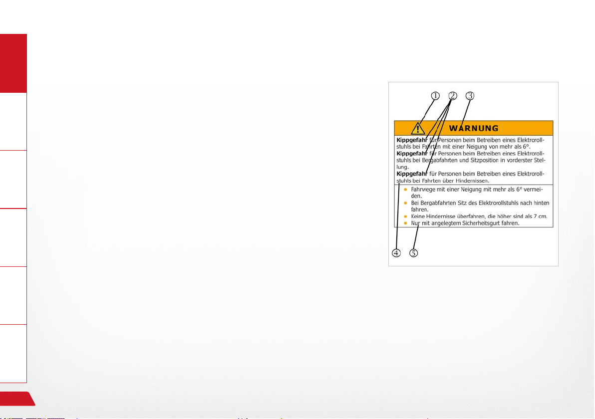
2.3.1 Structure of safety notices
You can nd the following information in the safety notes:
Information Prepare Operate Help Technology
› Warning or hazard symbol .
› Type and source of hazard .
› Signal word .
› Consequences of occurrence .
› Preventative action .
Fig. 3: Safety note
24
Safety note
Page 25

3. Safety note
3.1 General safety notes
3.1.1 Notes on usage
You must under all circumstances observe the following safety notes for your own safety, for that of people
in your vicinity and to protect the environment.
General
Safety note
DANGER!
InformationPrepareOperateHelpTechnology
Danger of crushing by contact with moving parts; e.g.
Through the rotation of the drive wheels or the Lifting movement of the lift arm and the horizontal movement of the seat.
Danger of fall through accidental movement of the electric
wheelchair due to the brake being left off.
Danger of fall through abrupt braking of the electric wheelchair
where the vehicle loses power.
› Do not make contact with moving parts.
› Accompanying persons should not make any contact with
danger areas when operating the electric wheelchair.
› The brake release lever must be in the "LOCK" position.
› Never switch off or cut off power to the electric wheelchair
while it is moving.
25
Page 26

General
Information Prepare Operate Help Technology
WARNING
Danger of tipping over for persons when using the electric
wheelchair on surfaces with a slope of more than 10°.
Danger of tipping over for persons when using the electric
wheelchair on downhill slopes with the seat position in its forwardmost position.
Danger of tipping over for persons when using he electric
wheelchair when driving over obstacles.
› Avoid paths with any inclination of more than 10°.
› When travelling downhill move the electric wheelchair's
seat to the back.
› Do not drive over obstacles higher than 60 - 70mm.
› Always drive with your safety belt on.
26
Safety note
Page 27

WARNING
Danger of personal injury when operating the electric
wheelchair in a state not conforming to its state upon delivery.
Material damage to the electric wheelchair through non-authorised or incorrectly installed components.
› Do not make any technical changes to your electric
wheelchair.
› Only operate your electric wheelchair in its original state
upon delivery.
› Use only original or authorised replacement parts.
› The operational condition of the electric wheelchair should
be checked before any use of it.
General
InformationPrepareOperateHelpTechnology
Safety note
27
Page 28

General
Information Prepare Operate Help Technology
WARNING
Danger of injury for persons when travelling with the electric
wheelchair over impassible surfaces.
Danger of fall and of tipping over for persons when operating
the electric wheelchair on surfaces with reduced load-bearing
capacity.
Material damage to the electric wheelchair through mechanical and physical forces due to travelling over impassible surfaces.
› Avoid travelling on slick, slippery, or greasy surfaces (e.g.
ice, snow, wet grass and leaves, etc.).
› Avoid travelling through water at a depth of 50mm or deeper.
› Observe the permitted total weight of the vehicle.
› Observe the load capacity (e.g. of bridges and over passes)
and condition of the travelling surface.
› Always drive with your safety belt on.
28
Safety note
Page 29

3.1.2 Notes on usage
Material damage to the electric wheelchair through overloading the vehicle.
Material damage to the electric wheelchair though the effect
of heat greater than 41°C.
Material damage to the electric wheelchair through battery
overload on downhill slopes.
› Use your electric wheelchair exclusively for the purpose for
which it was intended.
› Overloading the electric wheelchair (by an additional per-
son or other loads travelling on it) is prohibited.
› Protect your electric wheelchair from strong sun and other
sources of heat.
› Switch on electrical devices (e.g. the electric wheelchair's
lights) when travelling downhill.
General
CAUTION
InformationPrepareOperateHelpTechnology
Safety note
29
Page 30

General
3.1.3 Notes on transport
Information Prepare Operate Help Technology
CAUTION
Material damage to the electric wheelchair through slipping
from ramps or lift while being loaded.
Material damage to the electric wheelchair through being secured and transported improperly in and electric wheelchair
transporter.
› Secure ramp from slippage.
› Both the ramp and the electric wheelchair transporter must
be positioned on even and rm surfaces.
› The ramp or lift must be clean and dry.
› The ramp must be wider than the electric wheelchair and
should be clearly visible to allow corrective steering.
› Mount the ramp and lift in a single movement in order to
prevent the electric wheelchair rolling backwards.
› Secure the electric wheelchair in the transporter according
to the usual legal regulations.
› Use only suitable and authorised securing equipment.
› Switch the electric wheelchair off during transport.
30
Functional description
Page 31

4. Functional description
4.1 Manufacturing standard
The PARAVAN electric wheelchair is a multifunctional electric wheelchair which, due to its compact design,
is ideally suited to both indoor and outdoor usage.
The electric wheelchair is built and tested to ensure the highest possible level of safety for its operator and
his or her immediate environment. Our products are tested for freedom from any aws after their manufacture. However, if any failure in functioning should appear on your wheelchair, please contact your dealer or
PARAVAN GmbH directly in order to have that failure corrected as quickly as possible.
PARAVAN electric wheelchairs are manufactured and checked in conformity with:
› DIN EN 12184 Electric wheelchairs and scooters and their chargers.
and has been rated by this standard in Category B.
General
InformationPrepareOperateHelpTechnology
Functional description
31
Page 32

4.2 Appropriate usage
General
The PARAVAN electric wheelchair is functionally and structurally intended for the transport of a single person
Information Prepare Operate Help Technology
in indoor and outdoor areas. The interface in relation to operation by the user and the liability of the manufacturer of the electric wheelchair is the control panel, including its joystick and any optional operational units
for special operation.
The electric wheelchair is suitable exclusively for the applications listed in the section entitled
"Usage of the vehicle".
See Section "3 Notes on safety"
See Section "4.2.1 Usage of the electric wheelchair"
32
Functional description
Page 33

4.2.1 Usage of the electric wheelchair
- unproblematic
› Boarding by a single person with a maximum body weight of 160kg.
› Usage as driver or passenger seat, depending on the associated accessories.
› Usage in areas governed by German trafc law (public roads and thoroughfares), on condition that full and
fully functioning lighting is installed.
See Section "13 Driving the electric wheelchair"
- problematic or prohibited
› Use as a tractor means of transport of loads or more than one person.
› Use of the electric wheelchair in extreme climatic conditions (heat/cold/precipitation).
See Section "2.1 Disclaimer"
See Section "3 Notes on safety"
General
InformationPrepareOperateHelpTechnology
Functional description
33
Page 34

4.3 Approvals, certications
General
4.3.1 EU approval as a driver seat
The PARAVAN electric wheelchair with its special orthopaedic seat is
Information Prepare Operate Help Technology
rst electric wheelchair tted with an integrated seatbelt. In addition,
the electric wheelchair has passed its crash test and is approved as a
driver or passenger seat in a car modied by PARAVAN GmbH in accordance with
› The exceptional provisions in Section 70 of German Trafc Law.
The anchoring of the safety belt has been certied and approved in accordance with 76/115/EEC as has the seat in relation to its anchoring
in accordance with 74/408/EWG, as well as by
› Technical Reports Nos. 08-00719-CP-GBM and 08-00723-CP-GBM.
See Section "23 Annexes and technical documentation"
34
Fig. 4: TÜV Logo
Functional description
Page 35

4.3.2 Clearance certication as hazardous cargo (accumulator)
PARAVAN GmbH uses accumulators that are rated as "non-hazardous cargo" on condition that the relevant
accumulators are not suffering mechanical damage of any type.
The maintenance-free VRLA accumulators and the equally maintenance-free lead gel accumulators are clas-
sied as leak-proof, non-hazardous cargo for any form of transport according to:
› IATA, Rule A 67
› ADR, Rule 238 B
› IMDG, Rule 238.2
UN 2800 Special Provisions.
See "Clearance certication as hazardous cargo"
You will receive the appropriate Clearance certicate for your accumulators during the handover of
your wheelchair.
General
InformationPrepareOperateHelpTechnology
Functional description
35
Page 36

General
4.3.3 German Ordinance on Assistive Technology (HMV No.)
PARAVAN electric wheelchairs are approved according to the following assistive technology regulations:
Information Prepare Operate Help Technology
› Doctor's regulations in Nordwürttemberg – rules, regulations, provisions and services, Pages B 2 and – 1 ff
as an assistive technology under assistive technology number
› HMV No. 18.99.06.1048.
Approval from AOK on 09 June 2008 in accordance with Section 126 Para. 3 of German Social Code
V Catalogue of Assistive Technologies in accordance with Section 139 German Social Code V IKK
Federal Association - Federal Associations of Health Insurance Funds on 19 June 2008.
4.3.4 Denition of assistive technology (excerpt)
Assistive technologies are specialised medical services or objects that secure the success of a treatment by
their provision of a substitute, supportive or relief effect, or make it possible to overcome a physical disability. They include prostheses, orthopaedic and other assistive devices, aids to sight, specialised materials or
technical products...
36
Functional description
Page 37
5. Details relating to the product
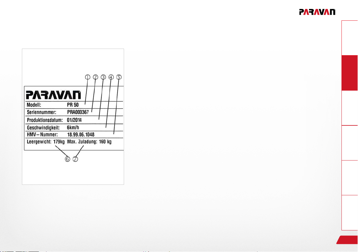
5.1 Trademark and type labelling (ratings plate)
You can read this information from the device's ratings plate. They are
very important in all correspondence with PARAVAM GmbH in guaranteeing that you receive the technically correct advice.
General
Fig. 5: Ratings plate
Details relating to the product
› Model designation
› Series number, Chassis no.
› Date of manufacture
› Max. speed
› HMV number
› Weight of electric wheelchair when empty
› Maximum load (body weight)
See Section "5.3.1 Your electrical wheelchair's ratings plate"
InformationPrepareOperateHelpTechnology
37
Page 38
5.2 Position of the type label (ratings plate)
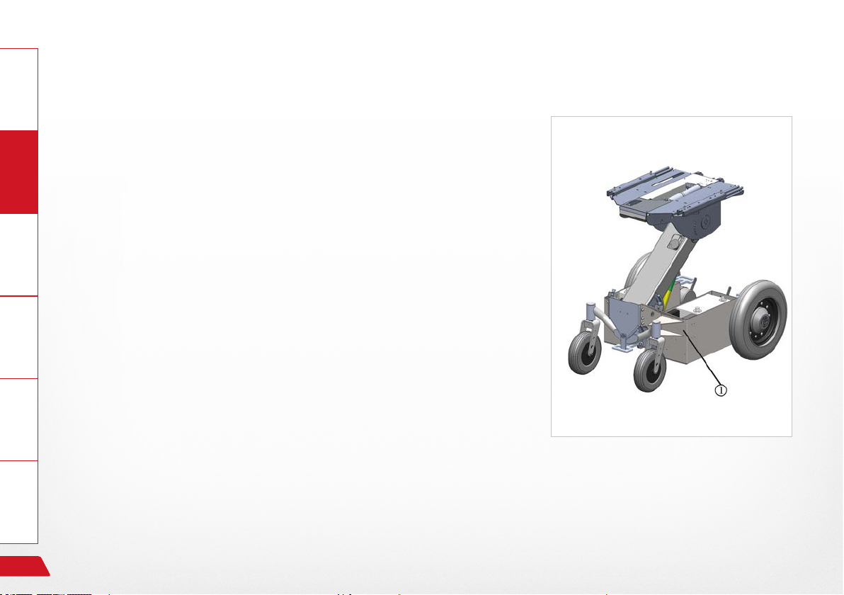
General
One copy of the type label (ratings plate) has been afxed to your elec-
Information Prepare Operate Help Technology
tric wheelchair. The type label (ratings plate) is about 70mm by 40mm
in size.
› The type label (ratings plate) is positioned on the lower right of your
wheelchair, next to the battery holder .
Fig. 6: Location, ratings plate
38
Details relating to the product
Page 39

5.3 Details on your electric wheelchair
Please make sure that these details are listed when the wheelchair is handed over to you or, if necessary,
enter the information yourself so that you have it to hand at all times.
Date of delivery/handover
›
Handed over by (dealer or branch ofce)
›
5.3.1 Your wheelchair's ratings plate
Stick a duplicate of your
ratings plate here!
General
InformationPrepareOperateHelpTechnology
Details relating to the product
39
Page 40
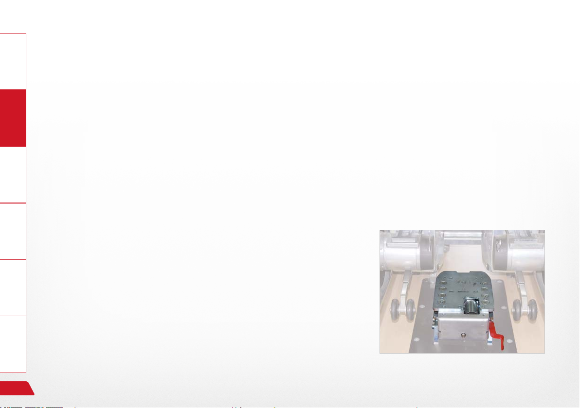
5.4 Accessories
General
5.4.1 Accessories included
› Charging device with charging cable.
Information Prepare Operate Help Technology
› User's Manual.
› Socket spanner with T grip, SW 13.
› Allen key, size 5.
› Magnetic key, optional, depending on equipment.
5.4.2 Accessories deliverable
› PARAVAN docking station to allow you to secure the electric
wheelchair easily and quickly in your vehicle, e.g. when the electric
wheelchair is being used as a driver's seat.
40
Fig. 7: Docking station
Description/Functioning or your electric wheelchair
Page 41

6. Description/Functioning or your electric wheelchair
6.1 The specially developed orthopaedic seat
The specially developed orthopaedic seat is an in-house development of PARAVAN GmbH that has been
adjusted precisely to the needs of our customers. It is equipped with the following:
› An integrated 3 or 4-point belt or lap belt, depending on the accessories delivered with the model.
› Special suspension in the seat to prevent strain on thigh muscles.
› A 4-position lumbar support in the seat back to ensure the correct position of the pelvis.
› A 6-axis adjustment of the seat arms with 12 individual positions to support your arms in an ideally
fatigue-free position.
› MeshTex textile covering made of active breathable nano bres to reduce the risk of pressure sores.
General
InformationPrepareOperateHelpTechnology
Description/Functioning or your electric wheelchair
41
Page 42

6.2 Joystick control
General
Using the joystick, the driving console and its integrated control panel, you can select and trigger all functions
Information Prepare Operate Help Technology
of the electric wheelchair; such as:
› The electric wheelchair's steering
› The electric wheelchair's braking behaviour
› Driving speed, control of the two drive motors
› Secondary functions, depending on the control panel and equipment being used.
6.3 Special controls
A variety of special controls can be used on the PARAVAN electric wheelchair, including the following:
› Chin control
› Environmental control
› etc.
42
If you have any special requirements or suggestions on this topic, please do not hesitate to get in
contact with us. Thank you.
Description/Functioning or your electric wheelchair
Page 43

6.4 Lift and tilt (seat inclination)
The electric wheelchair is equipped with a sturdy single-lever lift, which fully extended can reach a height of
80cm. This ensures that you have the largest possible radius of action in your everyday household and work
environment.
General
At the press of a button you can adjust the seat tilt (inclination) as follows:
› to the front, which will give you assistance in standing up
or
› to the rear, for relaxing, to prevent pressure sores, to support your lower body and to distribute your
weight more evenly.
See Section "11 The special orthopaedic seat, operation"
6.5 Vibration-damped foot rests
› Impact-damped, separate or conjoined in order to counter spasticity.
› Depending on the equipment, they may be electrically adjustable in terms of length and angle.
Description/Functioning or your electric wheelchair
InformationPrepareOperateHelpTechnology
43
Page 44
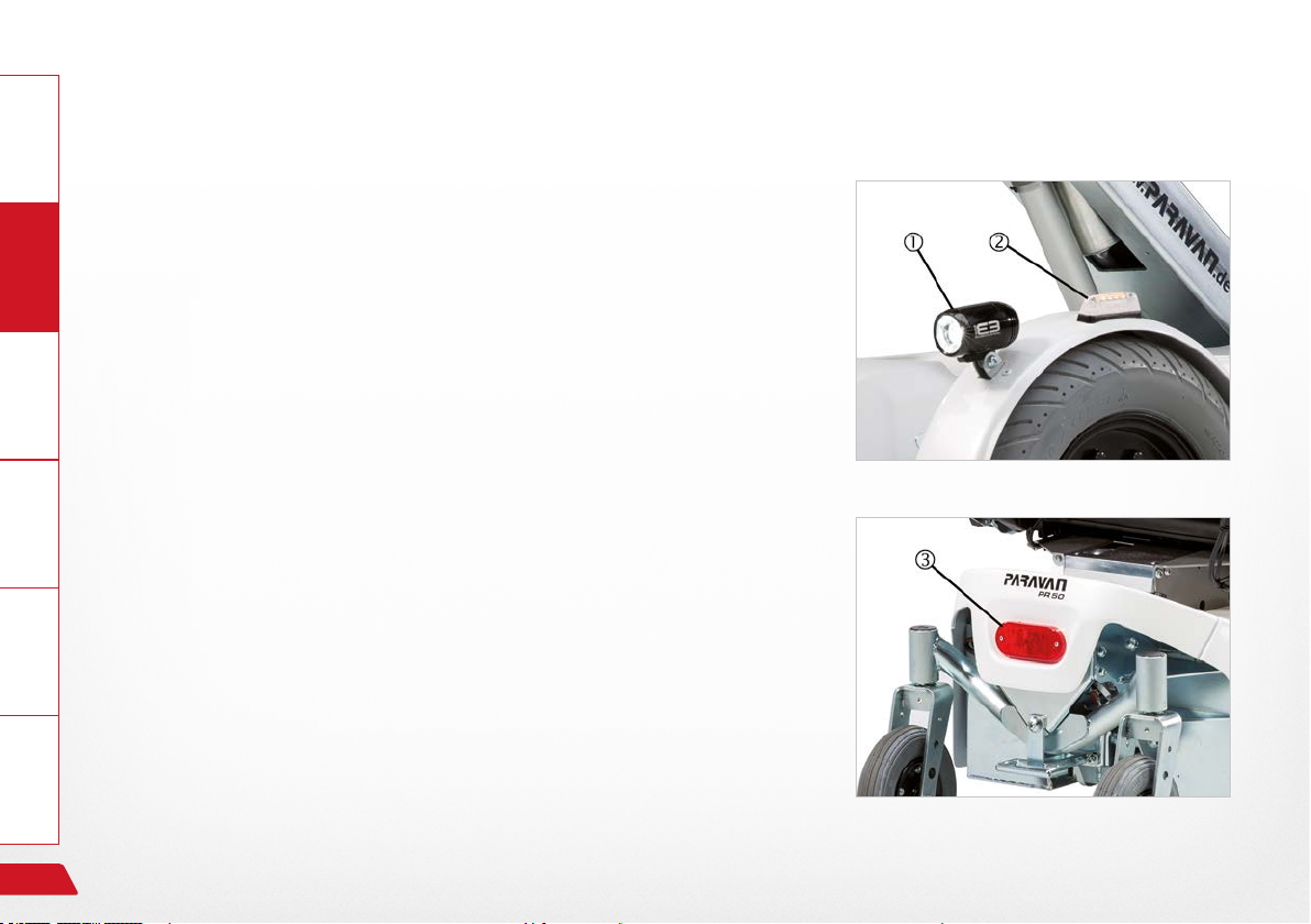
6.6 Safe for trafc conditions according to German trafc law
General
Optionally, the PARAVAN electric wheelchair can be enhanced to be-
Information Prepare Operate Help Technology
come a vehicle approved for use in road trafc using:
› LED headlights for the best possible illumination .
› LED directional indicators .
› LED rear lights for the best possible visibility .
› Lateral markings in the centres of the wheels using yellow
reectors.
6.6.1 Section 24 Special means of transport
Wheelchairs are mentioned in German trafc law. In that law,
it is stated:
› (1) Push and grip wheelchairs, sleds, prams, scooters, children's bi-
cycles and other similar means of transport are not vehicles in
the sense of German trafc regulations.
› (2) Medical wheelchairs and other wheelchairs as mentioned
in Paragraph 1 may circulate wherever pedestrian trafc is
permitted, but only at walking speed.
Fig. 8: Front illumination
Fig. 9: Rear illumination
44
Overview of the PARAVAN electric wheelchair
Page 45
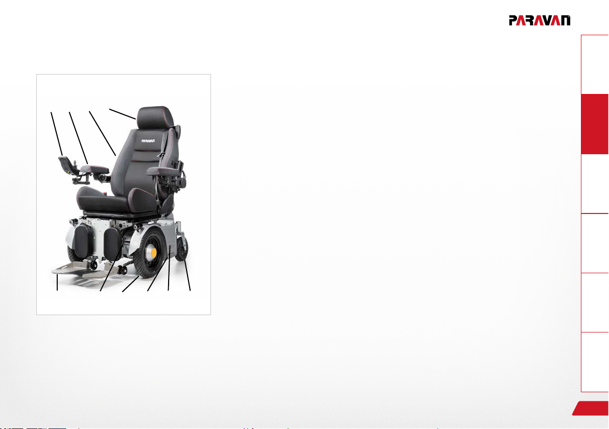
7. Overview of the PARAVAN electric wheelchair
7.1 Denition of vocabulary for parts and their positions
The following terms for components and parts will be used in this user's
① ② ③
④
⑤ ⑥ ⑦ ⑧ ⑨ ⑩
manual. Their position on the wheelchair is shown in the illustration.
› Control panel with joystick
› Repositionable armrest on multiple axes
› Back rest (electric)
› Head support
› Foot plate/foot rests
› Brake release lever, emergency release
› Drive wheel, puncture resistant as standard
› Battery holder
› Trimming
› Rear wheel, puncture resistant as standard
General
InformationPrepareOperateHelpTechnology
Fig. 10: Overview of wheelchair
Overview of the PARAVAN electric wheelchair
45
Page 46
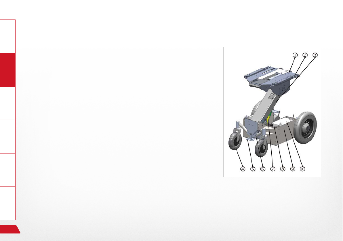
7.2 Denition of vocabulary for parts, place of installation, chassis
General
The following terms for components and parts will be used in this
Information Prepare Operate Help Technology
user's manual. Their assembled position on the chassis of your electric
wheelchair is shown in the illustration.
› Seat section
› Seat guides
› Lift arm
› Rear wheel
› Rigging eyelet, rear
› Floating axle
› Drive motor for lift arm
› Actuator module
› Battery holder
› Accumulator (battery)
Fig. 11: Components, rear of chassis
46
Overview of the PARAVAN electric wheelchair
Page 47
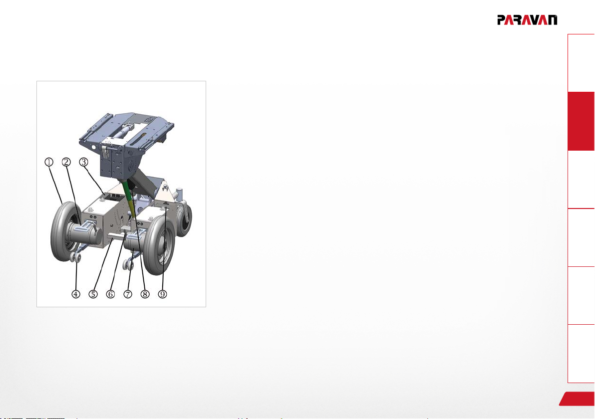
Fig. 12: Components, front of chassis
› Drive wheel
› Rigging eyelet
› Control devices
› Stabilizer, anti-tipper
› Fitting for docking station
› Brake release lever, emergency release
› Drive motor
› Lift motor with lifting rod and gearing
› Bracket for ancillary components
General
InformationPrepareOperateHelpTechnology
Overview of the PARAVAN electric wheelchair
47
Page 48

8. Handing over the electric wheelchair
8.1 Receiving your new electric wheelchair
General Information
Check that your your electric wheelchair is complete and compare the state in which it was delivered with
what is indicated on your order. Where there is any doubt, contact PARAVAN GmbH immediately!
Check (visually) that your electric wheelchair is in proper order. Report any damage that may be due to transport or delivery immediately in writing to your
› dealer, forwarder or medical supplier
Prepare
and
› PARAVAN GmbH
Operate Help Technology
See Section "1.1 Your manufacturer"
8.2 How your electric wheelchair is delivered to you
The electric wheelchair will be in the following state of assembly, ready for use and operation:
› Fully assembled and equipped in accordance with your order instructions.
› All components and auxiliary elements are pre-set to your body mass as it gured in your order.
› Ready charged accumulators.
48
Handing over the electric wheelchair
Page 49
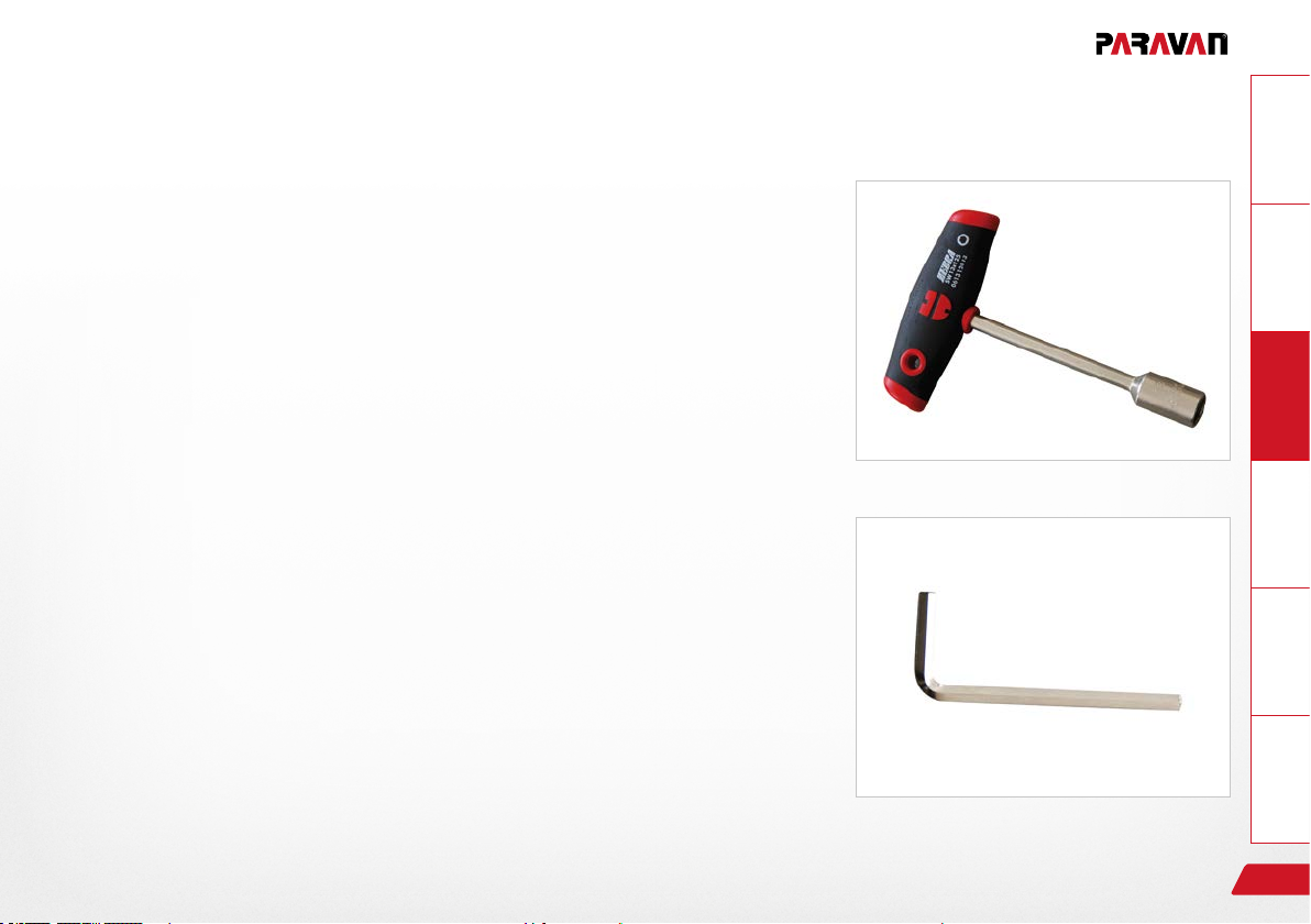
8.3 Tools included with the delivery
You will receive the following tools along with your electric wheelchair:
› Socket spanner with T grip, SW 13.
› Allen key, size 5.
GeneralInformationPrepareOperateHelpTechnology
Fig. 13: Socket wrench
Handing over the electric wheelchair
Fig. 14: Allen key
49
Page 50

9. Settings on your electric wheelchair; electronic
General Information
The settings and conguration needed for PARAVAN controls are very complex and for your own safety can
only be done by your service technician.
All parameters used in PARAVAN controls can be adjusted later to your needs and wishes. These parameters
include:
› All drive properties, such as starting and braking.
Prepare
› Steering behaviour.
Operate Help Technology
50
Should you need or would like to have adjustments made to control parameters, please contact
PARAVAN GmbH or your dealer.
See Section "1.1 Your manufacturer"
Settings on your electric wheelchair; electronic
Page 51

10. Settings on your electric wheelchair; mechanical
10.1 Receiving your new electric wheelchair
All mechanical components and equipment and operating elements are set to match your body mass.
However, if any adjustment should be necessary, then it can be made at any time. Your PARAVAN electric
wheelchair is build so that it can be adjusted to the needs of any body mass.
For your own safety, please make sure all mechanical settings and changes to the wheelchair's
equipment are made by your service technicians. No modications made by the customer are permitted!
See Section "23.4 Handover brieng"
GeneralInformationPrepareOperateHelpTechnology
Settings on your electric wheelchair; mechanical
51
Page 52
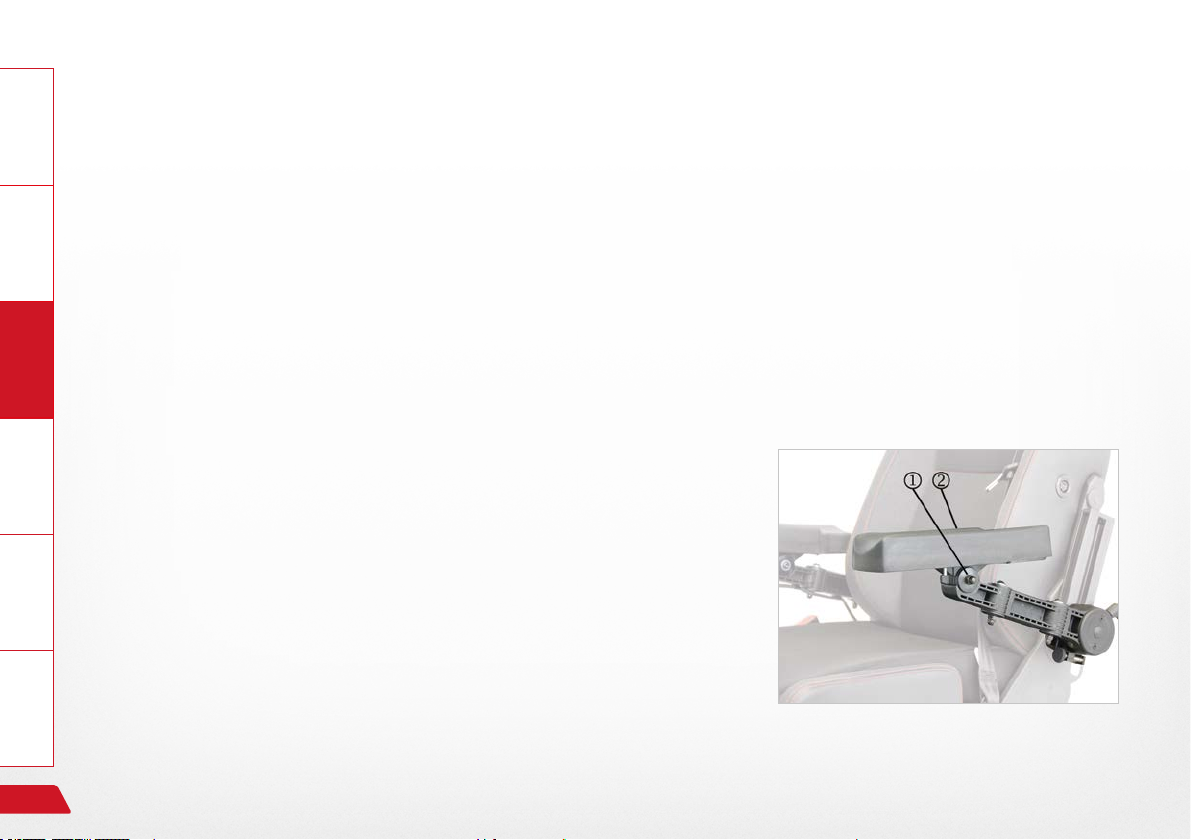
10.2 The armrest cushion
General Information
The armrest cushion can be folded vertically at its elbow and
can be slit horizontally into position forwards and backward,
thus allowing it to be set in a suitable position for every
purpose and for every body mass.
Prepare
Operate Help Technology
10.2.1 Setting the armrest cushion
This instruction applies both to the left and right hand cushion.
› Loosen the hexagonal cap nut .
› Swing the armrest cushion into the desired position
› Tighten the hexagonal cap nut to about 8 Nm.
52
See Section "8.3 Tools provided"
Fig. 15: Angled arm rest cushion
Settings on your electric wheelchair; mechanical
Page 53
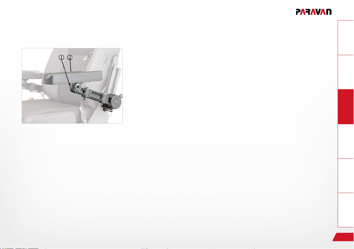
10.2.2 Setting the horizontal position of the armrest cushion
This instruction applies both to the left and right hand cushion!
Take the following steps in the following sequence when checking or
setting the position of the armrest cushion:
› Loosen the wing nut .
› Slide the armrest cushion back or forward into the desired positi-
on.
› Tighten up the wing nut until it is hand tight.
GeneralInformationPrepareOperateHelpTechnology
Fig. 16: Position of armrest cushion
Settings on your electric wheelchair; mechanical
See Section "8.3 Tools provided"
53
Page 54
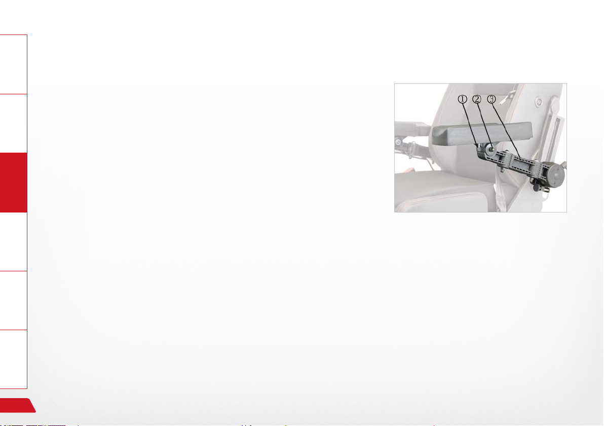
10.3 The armrest
General Information
The armrest can be moved in all directions horizontally (along its projection length) and vertically in terms of its height and of its angle, and
can thus be set to suit every body mass.
Prepare
Take the following steps in the following sequence when checking or
setting the position of the armrest:
Operate Help Technology
› Height of the armrest.
› Angle of the armrest.
› Projection of the armrest.
› Possible correction of the armrest cushion.
It may be necessary to make a further change in the position
of the armrest!
See Section "8.3 Tools provided"
54
Fig. 17: Checking the position of the armrest
Settings on your electric wheelchair; mechanical
Page 55
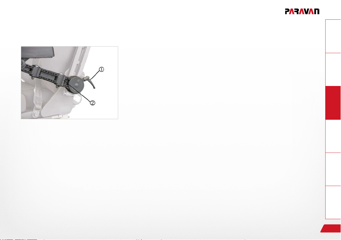
10.4 Set the height of the armrest
This instruction applies both to the left and right hand armrest!
› Eccentric clamp is loose → the arm rest is locked or xed in position.
› Eccentric clamp is tight → the arm rest is loose and can be moved.
Take the following steps in the following sequence when setting the
Fig. 18: Height of arm rest
height of the armrest:
› Tighten the clamping screw .
› Slide the armrest along its guide rail into the desired position.
› Loosen clamping screw .
In its form and function, the clamping screw is essentially an
eccentric clamp! That means that it works as follows:
GeneralInformationPrepareOperateHelpTechnology
Settings on your electric wheelchair; mechanical
55
Page 56
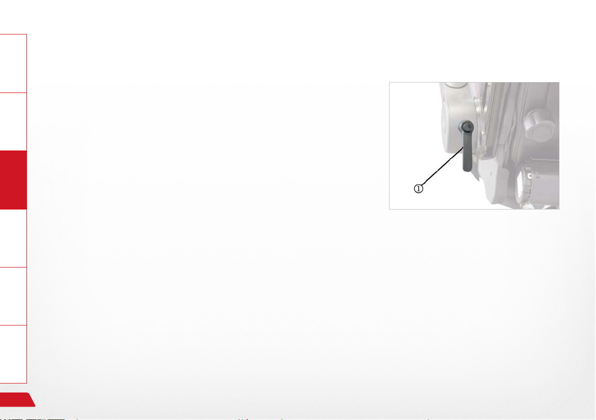
General Information
After changing the position of the armrest, you may need to re-position
the lever of the clamping screw, so that it does not represent any dan-
ger (of injury to passers by or of being knocked off).
› Lift up lever .
› Turn lever towards the rear, in direction of travel.
Prepare
› Lower lever .
Operate Help Technology
56
Fig. 19: Lever, clamping screw
Settings on your electric wheelchair; mechanical
Page 57
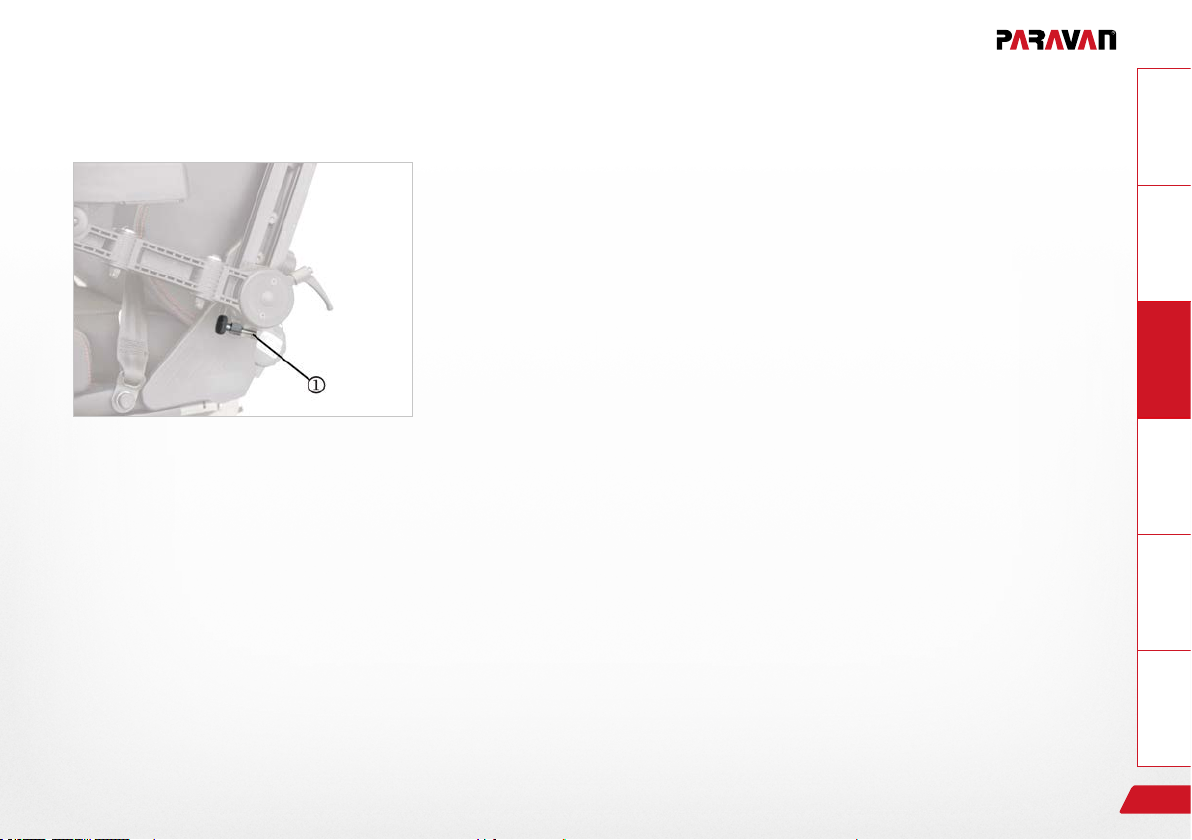
10.5 Set the angle of the armrest
The armrest pivots from its anchoring point. This allows the whole armrest to swivel upwards to allow you to sit in, stand up or move easily and
comfortably.
This instruction applies both to the left and right hand armrest!
You have the following settings available:
› Screw the knurled screw in → the angle of the armrest becomes
more acute.
Fig. 20: Armrest angle
› Screw the knurled screw out → the armrest lowers.
Do not force the knurled screw in or out. Raise the armrest a
little to remove pressure on the knurled screw.
GeneralInformationPrepareOperateHelpTechnology
Settings on your electric wheelchair; mechanical
57
Page 58
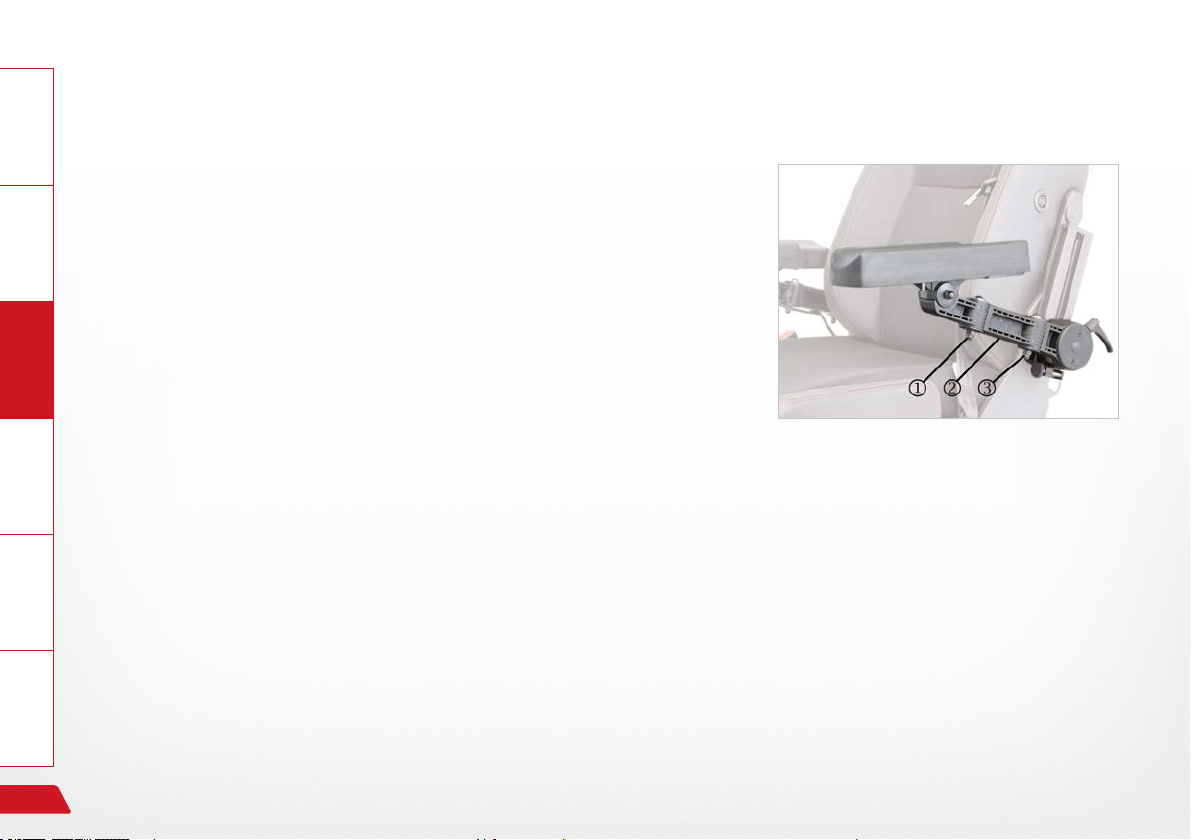
10.6 Set the projection of the armrest
General Information
This instruction applies both to the left and right-hand side, though you
may need to rotate the screw in the opposite direction!
Take the following steps in the following sequence when setting the
projection of the armrest:
Prepare
› Loosen the hexagonal cap nut .
› Loosen the hexagonal cap nut .
› Adjust the armrest cushion to the desired position.
› Tighten the hexagonal cap nut to about 8 Nm.
Operate Help Technology
See Section "8.3 Tools provided"
Fig. 21: Armrest projections
58
Settings on your electric wheelchair; mechanical
Page 59

10.7 Setting the movability of the control panel
The horizontal swivel mechanism of the control panel can be set to ad-
just its level of stiffness (i.e. in terms of the responsiveness and movability of the joint).
This level of stiffness can only be set by your service technici-
an!
See Section "8.3 Tools provided"
Fig. 22: Swivel mechanism
GeneralInformationPrepareOperateHelpTechnology
Settings on your electric wheelchair; mechanical
59
Page 60
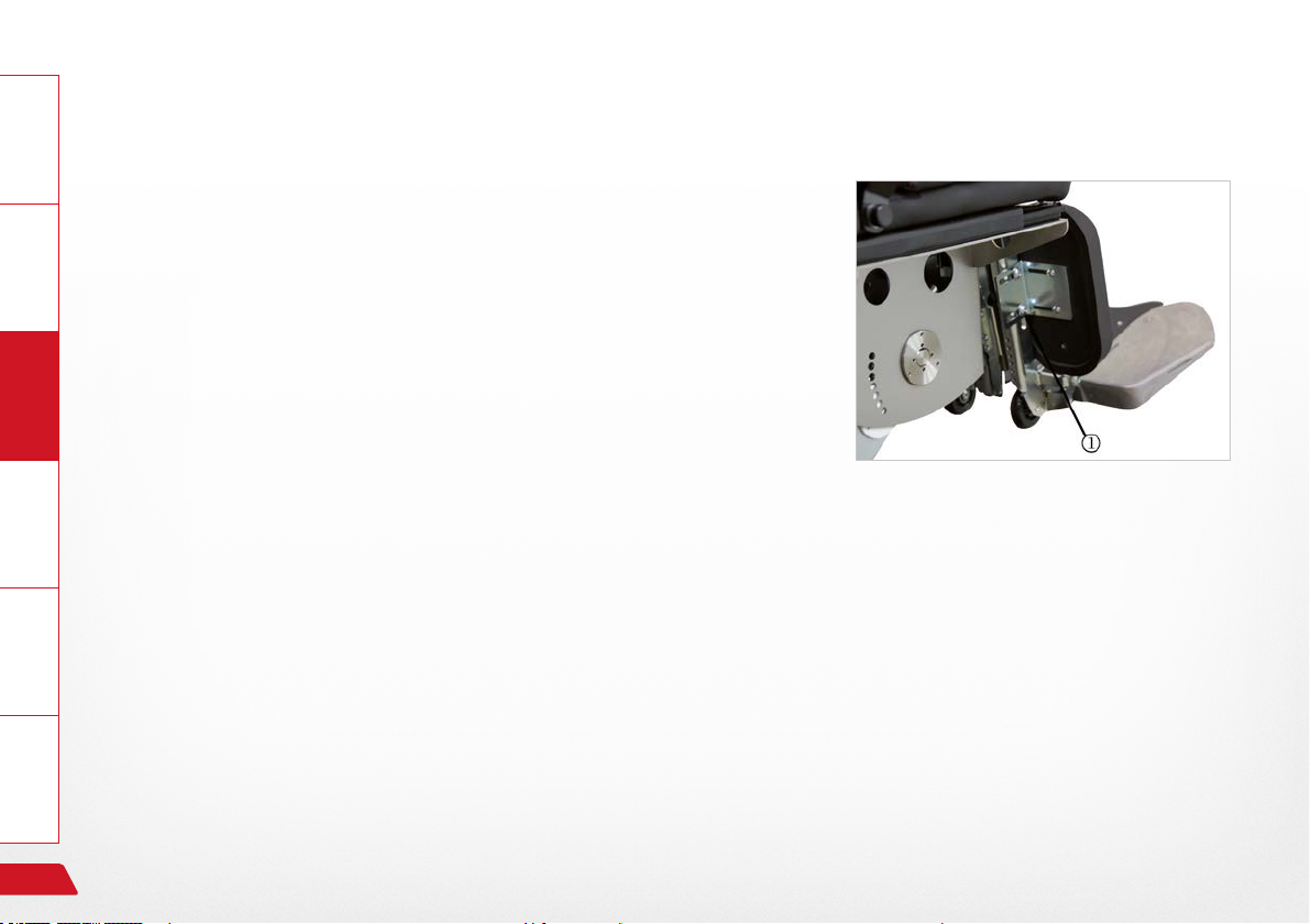
10.8 The foot support unit
General Information
Using the electric wheelchair's electrical angle and length compensation system, you can adjust the foot support unit electrically in terms of
its length and its angle in relation to the seat. The angle of the foot rest
can only be adjusted manually using an adjustment screw.
Prepare
10.8.1 Setting the lower leg length
The projection and length of the lower leg can be set electrically using
the PARAVAN control's length setting.
Operate Help Technology
› Select the menu in the control.
› Make your setting.
See Section "16 Controls"
If this adjustment mode is not sufcient for your needs, then
the foot support must be mechanically adjusted at the foot
support !
Fig. 23: Lower leg length
60
Settings on your electric wheelchair; mechanical
Page 61
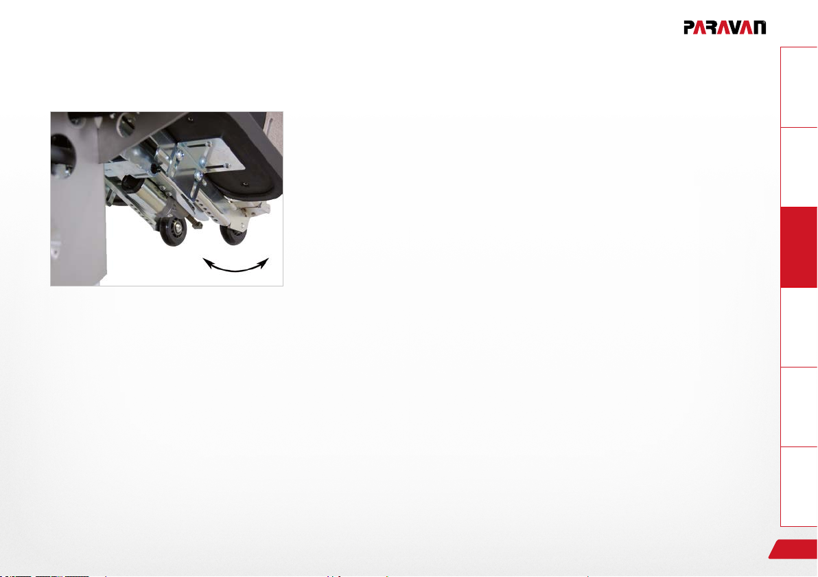
10.8.2 Setting the tibialis angle
Fig. 24: Tibialis angle
GeneralInformationPrepareOperateHelpTechnology
The projection of the lower leg and of the tibialis angle (between the upper and lower leg) can be made using the angle setting of the PARAVAN
control, depending on how your model is equipped.
› Select the menu in the control.
› Make your setting.
See Section "16 Controls"
Settings on your electric wheelchair; mechanical
61
Page 62
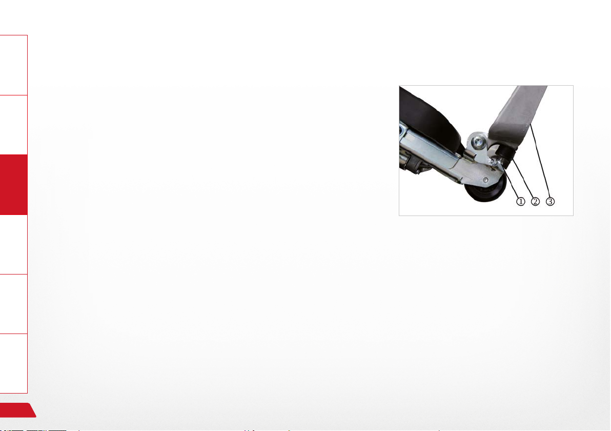
General Information
10.8.3 Setting the foot rest angle
The angle of the foot rests can be set separately for each foot rest to
match your individual needs.
The following settings are available:
› Screw the adjustment screw inwards -> the foot rest is lowered.
Prepare
› Screw the adjustment screw outwards -> the foot rest is raised.
Operate Help Technology
Take the following steps in the following sequence when setting the
angle of the foot rest:
› Raise the foot rest .
› Loosen the lock nut .
› Screw the adjustment screw in or out as required.
› Check your setting (lower the foot rest).
› Tighten the lock nut to about 8 Nm.
62
Do not force the adjustment screw in or out. Raise the foot
rest a little to remove pressure on the adjustment screw.
Fig. 25: Foot rest angle
Use of the special orthopaedic seat
Page 63
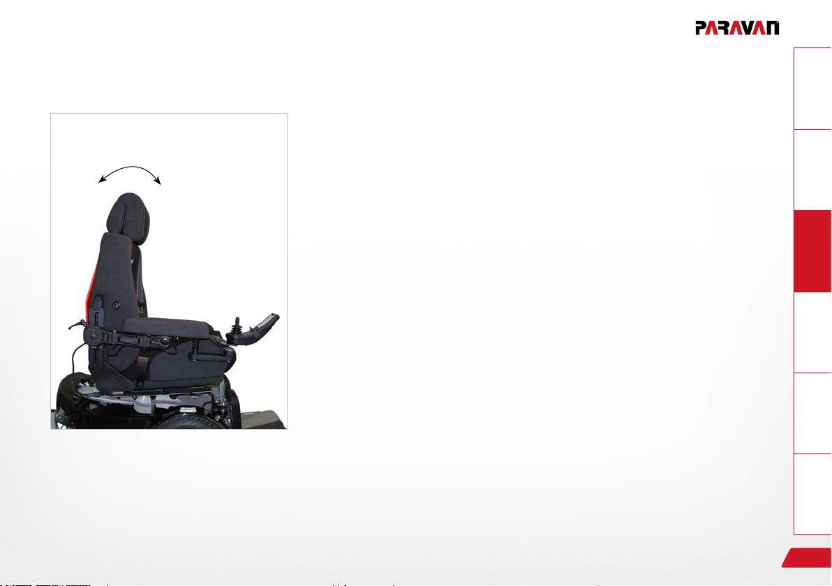
11. Use of the special orthopaedic seat
11.1 Setting the back support
11.1.1 Setting the back support angle
The back support and the back support angle can be changed electrically using the PARAVAN control.
› Select the menu in the control.
› Make your setting.
Fig. 26: Back support angle
GeneralInformationPrepareOperateHelpTechnology
See Section "16 Controls"
Use of the special orthopaedic seat
63
Page 64
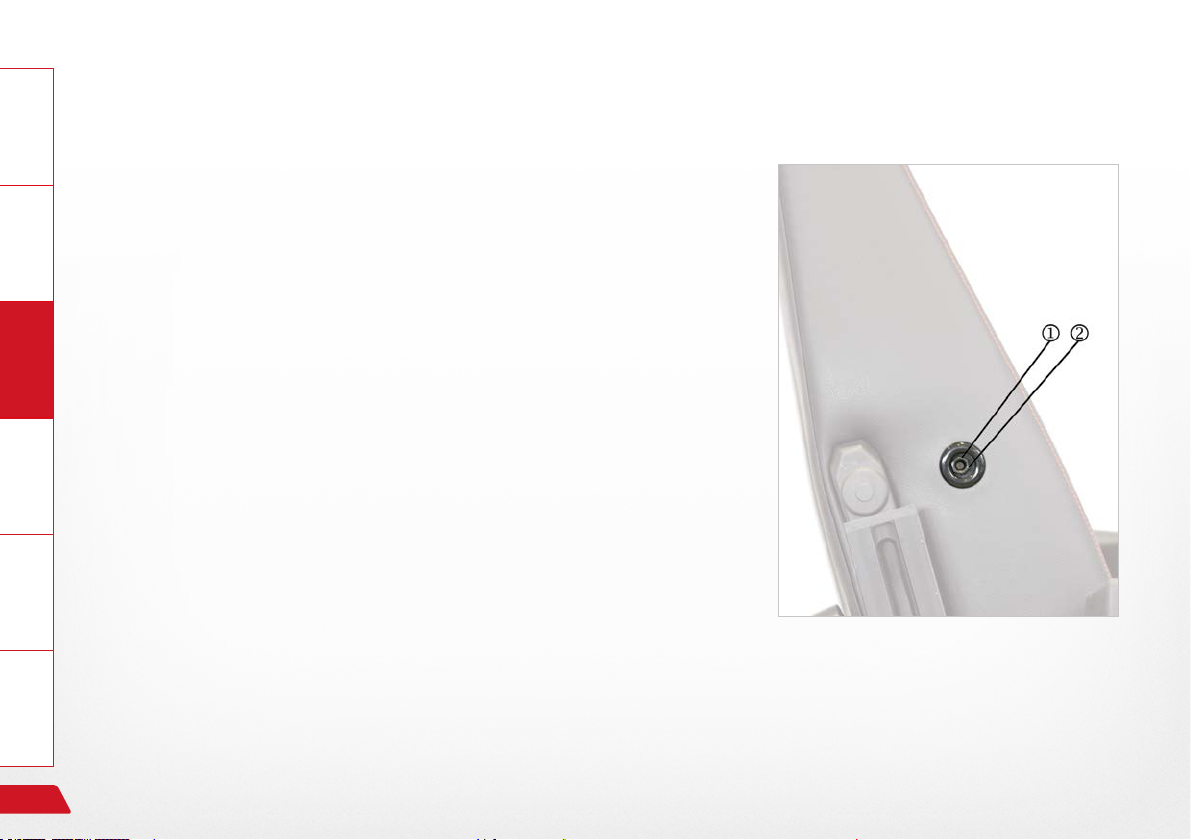
General Information
11.1.2 Setting the side bolsters (thoracic supports)
If you need a lateral guide or support for your upper body (thorax), you
can adjust the left and right-hand side bolsters (thorax supports) sepa-
rately. This adjustment may need to be re-made due to weather conditions and the clothing that weather conditions require.
This instruction applies both to the left and right hand armrest!
Prepare
You have the following settings available:
› Turn the adjustment screw clockwise → The thoracic support
Operate Help Technology
moves towards the midpoint of the seat.
› Turn the adjustment screw anticlockwise → The thoracic support
moves outwards.
See Section "8.3 Tools provided"
Fig. 27: Thoracic supports
64
Use of the special orthopaedic seat
Page 65
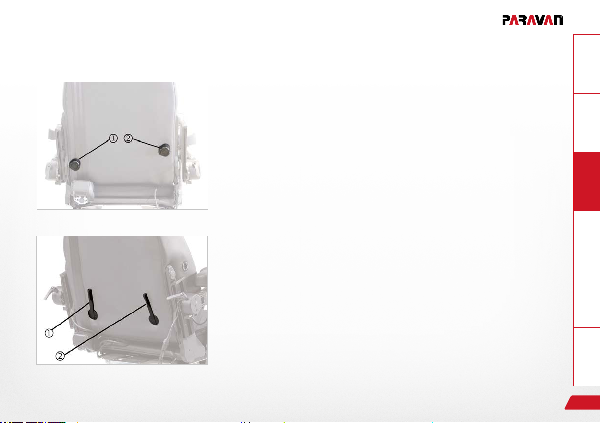
11.2 Setting the lumbar support
If you need an adjustment of the curvature in the area of your lumbar
vertebrae, you can adjust the lumbar support to your individual needs.
The adjustment of the level of support, modifying the position of the
pelvis, can be made steplessly in terms of height and curvature using a
4-way mechanism.
You have the following settings available:
Height adjustment, max. adjustment range ca. 70mm:
GeneralInformationPrepareOperateHelpTechnology
Fig. 28: Lumbar support, vers. 1
Fig. 29: Lumbar support, vers. 2
Use of the special orthopaedic seat
› Turn adjustment knob or lever clockwise
→ lumbar support moves upwards.
› Turn adjustment knob or lever anticlockwise
→ lumbar support moves downwards.
Support curvature, max. curvature ca. 25mm:
› Turn adjustment knob or lever clockwise
→ lumbar curves outwards.
› Turn adjustment knob or lever anticlockwise
→ the curvature of the lumbar support reduces.
65
Page 66
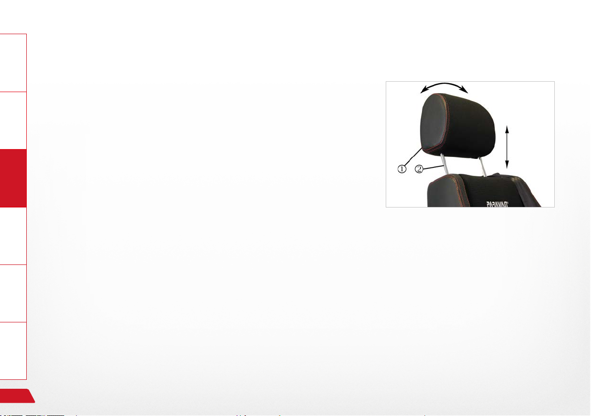
General Information
11.2.1 Setting the head support
If you need the head support position to be change, you can adjust the
height of the head support to your individual needs in 5 stages.
You have the following settings available:
Adjusting head inclination:
Prepare
› Push the head support into the required inclination
→ push the head support up backwards or forwards.
Operate Help Technology
Height adjustment in ve stages:
› Push the head support into the required stage
→ pull the head support upwards or push it downwards. The
head supports have ve stages.
In order to remove the head support (e.g. at the hairdresser) you must
pull it up over the nal stage and pull it free. Do the same in reverse to
replace it.
66
Fig. 30: Head support
Use of the special orthopaedic seat
Page 67

11.2.2 Setting your sitting position
The seat can be moved forward or backwards using the PARAVAN control if you have chosen this optional special accessory.
› Select the menu in the control.
› Make your setting.
Fig. 31: Sitting position
GeneralInformationPrepareOperateHelpTechnology
See Section "3 Notes on safety"
See Section "16 Controls"
Use of the special orthopaedic seat
67
Page 68

11.3 Setting your lying position
General Information
The seat can be moved into a lying position using the PARAVAN control.
The lying position function is not provided within the control. It must be
set individually by the user.
Prepare
Take the following steps in the following sequence when setting the
lying position:
› Select the menu in the control.
Operate Help Technology
› Move the lift arm upwards.
› Set the required tilt for the seat. (Optional special equipment)
› Set the required tilt for the back support.
› Set the foot support angle and length. (Optional special equipment)
See Section "16 Controls"
Fig. 32: Lying position
68
Use of the special orthopaedic seat
Page 69
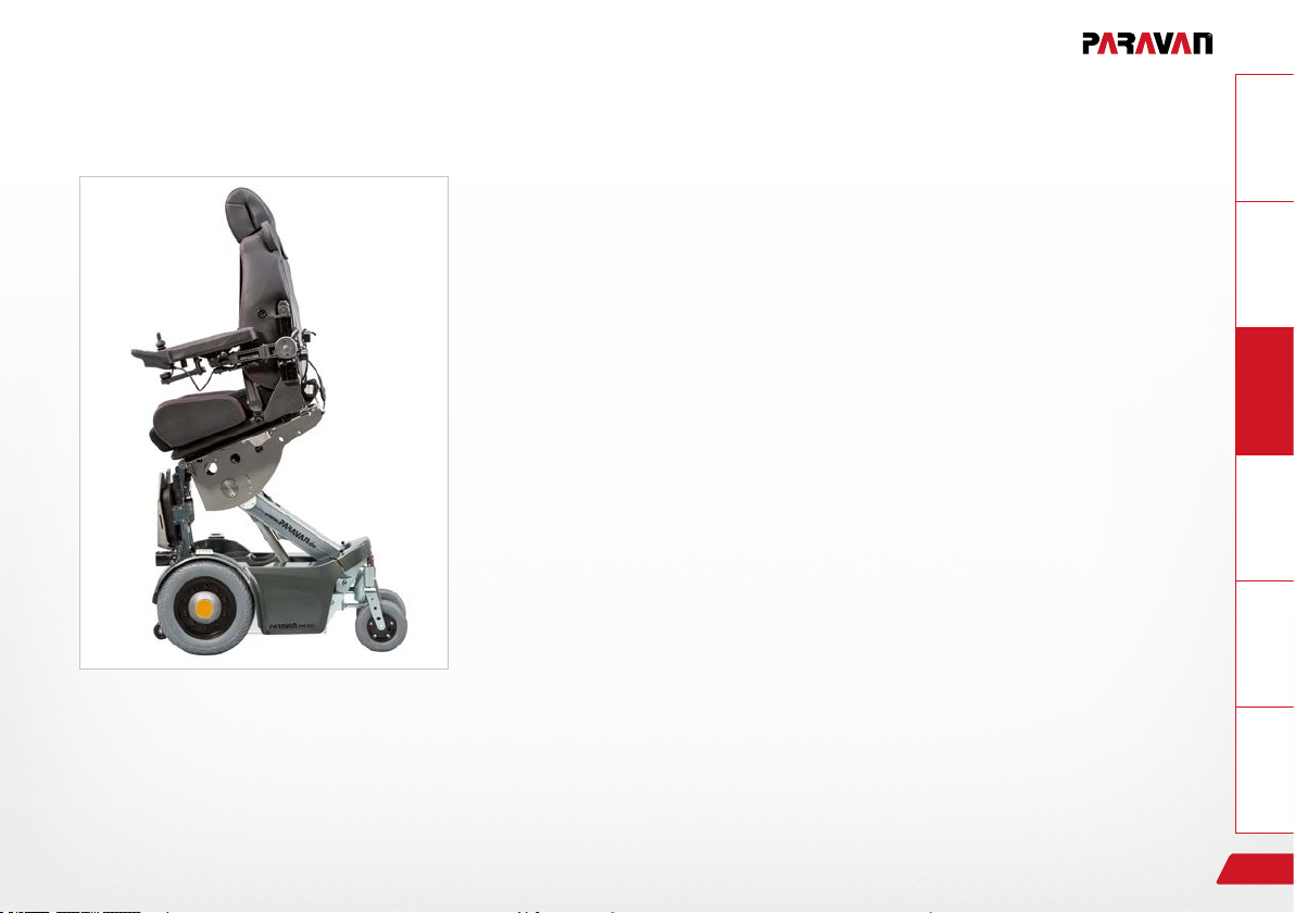
11.4 Setting the standing up position
The seat can be moved into a stand-up position using the PARAVAN
control.
The stand-up position function is not provided in the control. It must be
set individually by the user.
Take the following steps in the following sequence when setting the
stand-up position:
› Select the menu in the control.
› Move the lift arm up to the height of your bottom.
› Fold the foot rest up.
› Tilt the seat forward.
› Push off from the seat and stand up.
See Section "16 Controls"
Fig. 33: Stand-up position
GeneralInformationPrepareOperateHelpTechnology
Use of the special orthopaedic seat
69
Page 70
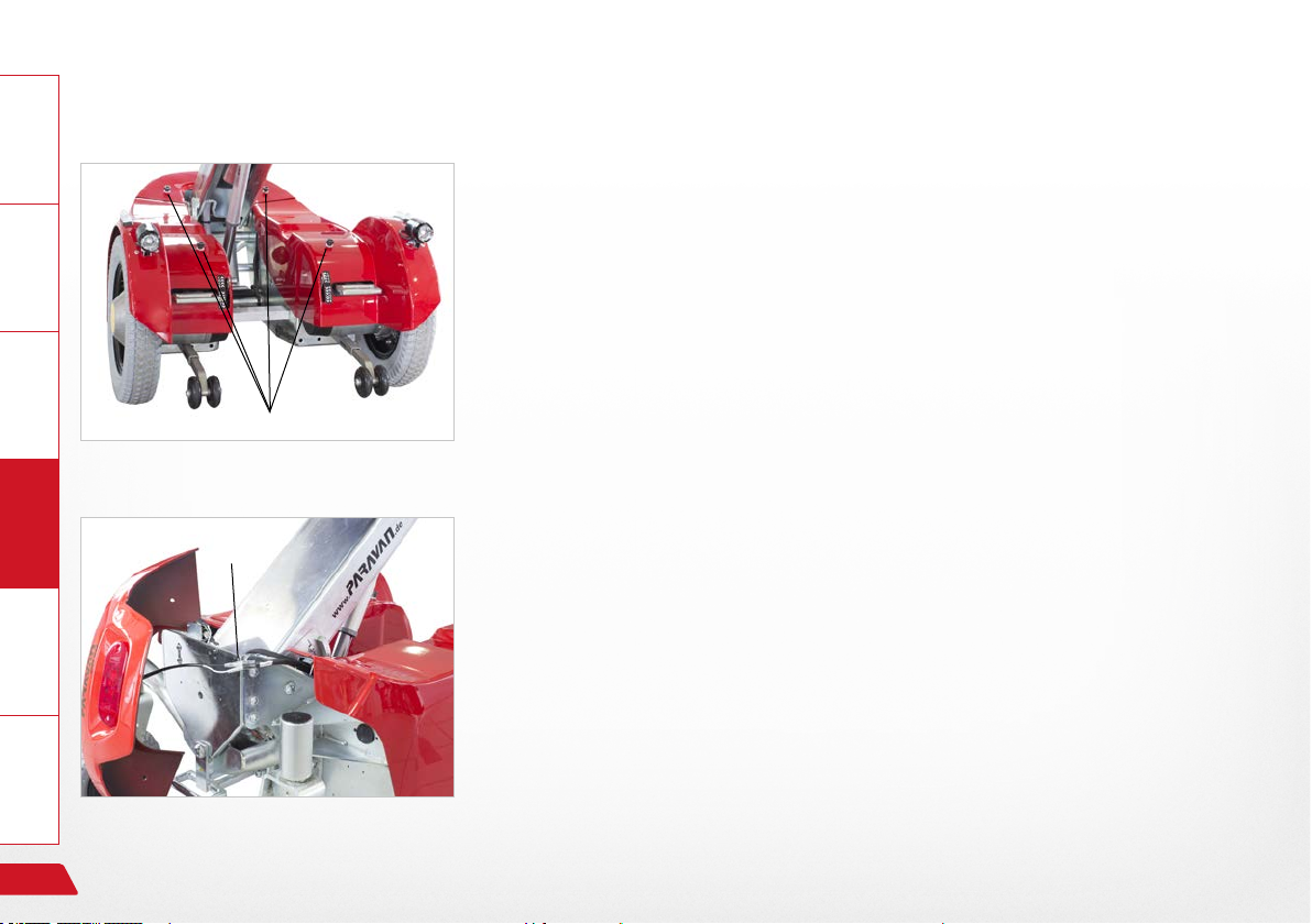
12. Removing and reattaching the chassis cladding
12.1 Removing and reattaching the rear cladding
General Information Prepare Operate Help Technology
The chassis cladding can be removed for maintenance, repair or
cleaning.
Take the following steps in the following sequence when removing and
reassembling the rear cladding:
› Loosen and remove knurled screws .
Fig. 34: Rear cladding
Fig. 35: Rear light and cable
70
Put aside the knurled screws and plastic washers.
› Remove the rear cladding carefully.
› Disconnect the cable for the rear light at the connection.
› Reassemble in the opposite sequence.
Removing and reattaching the chassis cladding
Page 71
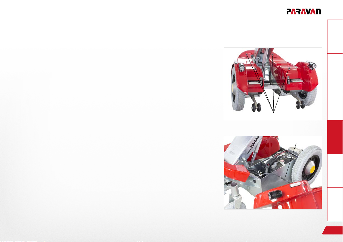
12.2 Removing and reattaching the side cladding
The chassis cladding can be removed for maintenance, repair or
cleaning.
Take the following steps in the following sequence when removing and
reattaching the side cladding:
› Loosen and remove knurled screws .
› Remove rear cladding.
See Section "12.1 Removing and reattaching the chassis clad-
ding"
GeneralInformationPrepareOperateHelpTechnology
Fig. 36: Side cladding
› Raise the side cladding at rear.
› Disconnect the cable for the front headlight and directional indica-
tor at the connection.
› Remove side cladding from the front.
› Reassemble in the opposite sequence.
Make sure the plastic washers are present, as they protect the
chassis components from damage.
Removing and reattaching the chassis cladding
Fig. 37: Front headlight, cable
71
Page 72

13. Driving your electric wheelchair
13.1 Insurance, civil liability insurance
General Information Prepare Operate Help Technology
We recommend speaking with your insurance advisor before starting use, so that the use of the electric
wheelchair is included in your insurance policies – in particular in your civil liability insurance.
Please observe that for use on the public roads you may be legally required by the relevant legislati-
on to have an insurance policy for use of your electric wheelchair.
WARNING
Danger of personal injury when operating the electric
wheelchair in a state not conforming to its state upon delivery.
Material damage to the electric wheelchair through non-authorised or incorrectly installed components.
› Do not make any technical changes to your electric
wheelchair.
› Only operate your electric wheelchair in its original state
upon delivery.
› Use only original or authorised replacement parts.
› The operational condition of the electric wheelchair should
be checked before any use of it.
72
Driving your electric wheelchair
Page 73
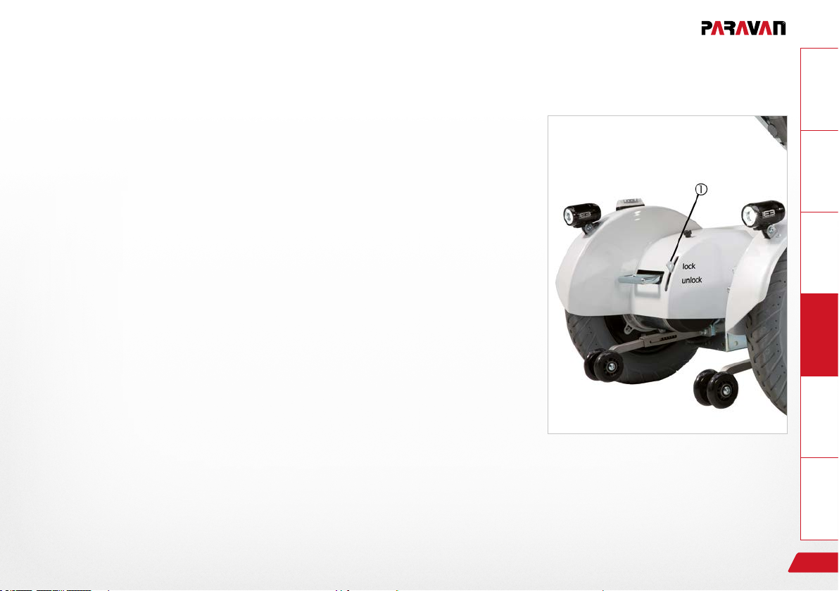
13.2 Functional checking before driving
For your own safety, you must check the following points before beginning any trip.
You may need to involve a second person for such a check.
› Check that the brakes are working.
The brake release lever must be positioned on "LOCK";
i.e. in its upward position.
› Charge state of your accumulators.
› Functional check on the lighting system:
See Section "13.10.1 Using the brake release lever (emergen-
cy release)"
GeneralInformationPrepareOperateHelpTechnology
See Section "21 Electrical system"
Driving your electric wheelchair
Fig. 38: Brake release lever (emergency release)
73
Page 74

13.3 Buckling the safety belt
General Information Prepare Operate Help Technology
Fig. 39: Fastening the seat belt
Listen for an audible clicking into place of the buckle latch
in the belt fastener when buckling the safety belt.
The function of the belt fastener is similar for all belt variants,
including:
› 2-point belt (lap belt).
› 3-point belt in driver or passenger version.
› 4-point belt (suspender belt).
› Multipoint belt (special belt with several anchor points).
Fig. 40: Belt fastener
74
Driving your electric wheelchair
Page 75

13.4 Controlling the electric wheelchair's travel direction
GeneralInformationPrepareOperateHelpTechnology
The electric wheelchair is steered using the joystick on the
drive panel.
The following basic steering options are available to you when you put
the joystick in the following positions:
› Joystick pushed forward → the electric wheelchair travels forward.
› Joystick to left or right → the electric wheelchair changes its direc-
tion into the selected direction.
› Joystick pulled backward → the electric wheelchair travels back-
wards.
› Joystick in neutral position (in the middle) → brakes are active, no
movement.
To prevent the wheelchair from moving in an undesired way, do
not make any sudden movements (drive commands) using the
joystick!
area.
Practice using the controls in a safe and obstacle-free
Fig. 41: Joystick
V
L
R
H
Driving your electric wheelchair
75
Page 76

13.5 Driving a curve
General Information Prepare Operate Help Technology
The PARAVAN electric wheelchair is equipped with front-wheel drive. This means that when steering
(driving on curves) the rear of the vehicle swings outwards.
How to drive around a curve:
› Press the joystick in the desired direction of movement (forwards or backwards).
and at the same time
› Press the joystick in the desired direction of steering (left or right).
For example:
› Push the joystick to the top right (to "two-o'clock") from the user's point of view.
→ the electric wheelchair will steer right.
See Section "3 Notes on safety"
76
Driving your electric wheelchair
Page 77

13.6 Braking your electric wheelchair
13.6.1 Braking systems on your electric wheelchair
In order to guarantee the highest possible level of safety, the PARAVAN electric wheelchair uses two braking
(safety) systems that work independently of each other. The functions of each of these safety systems are
as follows:
› Safety during travel:
By releasing the joystick (the joystick will always return to its neutral position in the middle) during travel,
the motor brake engages automatically and brakes the electric wheelchair.
› Safety where power fails or cuts out:
If the supply of current should become interrupted – e.g. by a the battery losing its charge – the magnetic safety brake is triggered and the electric wheelchair will come to a stop. Where this happens it can
only be released again mechanically and moved manually.
See Section "13.10.1 Using the brake release lever (emergency release)"
GeneralInformationPrepareOperateHelpTechnology
Driving your electric wheelchair
77
Page 78

13.7 Braking the electric wheelchair
General Information Prepare Operate Help Technology
The braking mechanism; i.e. the process from initiating the braking process until the electric wheelchair comes to a stop, depends very heavily on a number of factors, such as:
› Surface and nature of the surface being travelled on.
› Total weight of the electric wheelchair (vehicle plus driver).
On braking during cruising speed at about 6km/h, your electric wheelchair has a braking distance of
about 1 metre!
When the brake is engaged at high speeds, specially in downhill travel, the electric wheelchair may
roll or skid. For this reason, avoid braking suddenly!
78
Driving your electric wheelchair
Page 79

13.8 Travelling on hills, uphill and downhill travel
For your own safety you must observe and follow the following advice during uphill and downhill travel:
› Set the seat position to its hindmost position and scantlings back slightly in order to prevent slipping.
› Always drive with your safety belt on.
› Avoid braking suddenly during downhill travel to prevent the the electric wheelchair from rolling or skid-
ding.
› During uphill and downhill travel, select a low drive level and speed to prevent you from losing control of
the electric wheelchair at any point.
› The stability of the electric wheelchair cannot be guaranteed during uphill or downhill travel involving a
slope of more than 7°; such travel will involve danger of the electric wheelchair tipping over.
› When going downhill, the power generated is channelled into the accumulators. If the battery was fully
charged on starting travel, the safety system switches to emergency stop, in order to prevent damage to
the vehicle's electronic components through electrical overload. If this should occur, switch on an electrical device (e.g. the lights) to run down the battery, and then continue your journey.
During uphill and downhill travel, the brake release lever should be set to "LOCK". The motor brake
only functions in "LOCK" position. Otherwise, the vehicle will travel downhill with no brake being
applied.
GeneralInformationPrepareOperateHelpTechnology
See Section "13.10.1 Using the brake release lever (emergency release)"
Driving your electric wheelchair
79
Page 80

13.9 The driving programmes / drive levels
General Information Prepare Operate Help Technology
The PARAVAN electric wheelchair has four different driving programmes, or drive levels. You can select the
drive level you want or nal driving speed of your electric wheelchair on the control panel.
You can reach the maximum nal speed of the relevant drive level by pushing the joystick forward as far as
it goes.
The functions of each of the drive levels are as follows:
› Drive level 1
Highest level of control of the electric wheelchair
20% of nal speed, for travelling around rooms.
› Drive level 2
40% of nal speed.
› Drive level 3
60% of nal speed.
› Drive level 4
80% of nal speed.
› Drive level 5
For experienced drivers/users only
Maximum nal speed.
80
See Section "16 Controls"
Driving your electric wheelchair
Page 81
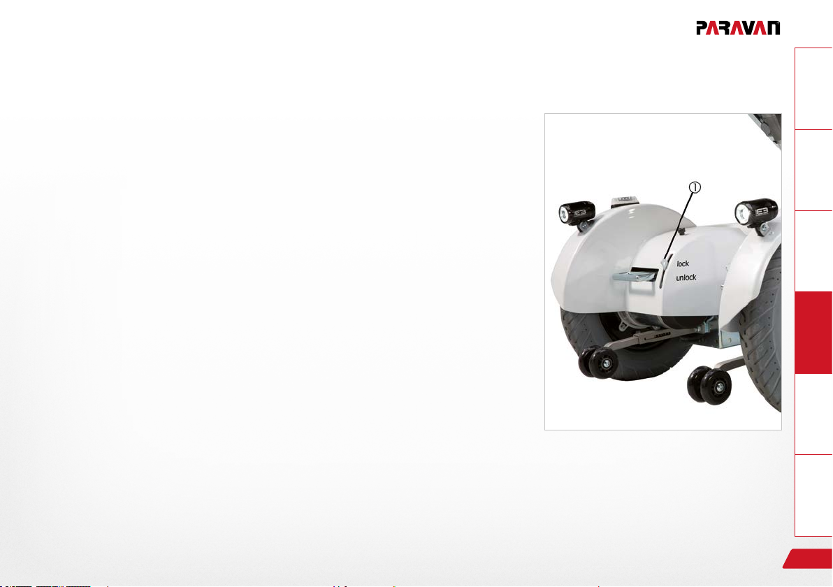
13.10 Driving manually, manual operation
13.10.1 Use of the brake release lever (emergency release)
› If you want to push the electric wheelchair, you must move both
brake release levers on the left and right-hand side to "UNLOCK"
(their downward position).
Do not switch to "UNLOCK" on sloping surfaces! In this setting
the drive motor has no braking function!
Settings on the brake release lever
LOCK
› Lever in its upward position
= drive, braking system active!
UNLOCK
› Lever in its downward position
= for pushing, braking system disabled!
GeneralInformationPrepareOperateHelpTechnology
Fig. 42: Brake release lever (emergency release)
Driving your electric wheelchair
81
Page 82

13.11 Terrain requirements, surfaces
General Information Prepare Operate Help Technology
Danger of tipping over for persons when using the electric
wheelchair on surfaces with a slope of more than 10°.
Danger of tipping over for persons when using the electric
wheelchair on downhill slopes with the seat position in the
most forward position.
Danger of tipping over for persons when using he electric
wheelchair when driving over obstacles.
› Avoid paths with any inclination of more than 10°.
› When travelling downhill move the electric wheelchair's
seat towards the back.
› Do not run over obstacles higher than 60 - 70 mm.
› Always drive with your safety belt on.
13.11.1 Ability to ford, or drive through water
WARNING
› Travel through water may lead to damage to electronic components (motors, control devices, etc.)
and to accumulators due to water penetration.
82
Driving your electric wheelchair
Page 83

13.11.2 Climbing and overtaking capacity
› If you drive over obstacles higher than 60 to 70mm you and your electric wheelchair may become
caught on the obstacle due to the battery casing and may be immobilised or overturn.
13.11.3 Load-bearing capacity
› Do not drive on surfaces on which there is a danger that you may break through them and thus be
come immobilised or overturn. Always consider the total weight of the vehicle.
See Section "22.1 Technical information and dimensions"
13.11.4 Impassible surfaces or areas
› Driving on impassable surfaces or areas will risk the you and your electric wheelchair becoming im
mobilised or overturning.
13.11.5 Slippery surfaces, traction
› Your electric wheelchair can lose grip when driving on slippery surfaces (e.g. unsurfaced ramps, wet
grass, snow, ice, etc.). That means its drive and braking power are no longer effective.
GeneralInformationPrepareOperateHelpTechnology
Driving your electric wheelchair
83
Page 84

14. Parking and storing your electric wheelchair
General Information Prepare Operate Help Technology
In order to prevent damage to your electric wheelchair, you must observe the following rules when you park
it, e.g. overnight, or for any longer period of time:
› Connect it up with the recharger.
› Select a dry parking position.
› Do not expose your electric wheelchair to high or low temperatures.
› Cover your electric wheelchair with a suitable covering.
14.1 Immobiliser/key function
Depending on the equipment of your electric wheelchair, there are two different ways of securing it from
unauthorised use.
84
Secure your electric wheelchair from unauthorised use! You are responsible to ensure that your
electric wheelchair is properly parked!
Parking and storing your electric wheelchair
Page 85

15. Loading and transporting your electric wheelchair
Your electric wheelchair should always be switched off and properly secured or lashed down during
transport. Use loading devices such as:
› ramps, lifts and hoists
with sufcient load-bearing capacity.
15.1 Rules when loading wheelchairs
The following rules must be followed when loading:
› The maximum rated height indicated on the ramp must be greater than the height to be climbed from the
oor to the height of the supporting edge (in a car, for example, the oor of the car boot).
› Check the load capacity of the ramp(s), of the life or of the hoist.
› For safety reasons, your electric wheelchair should be loaded into a car or onto the necessary ramps only
unoccupied (without any person or baggage on board).
› The loading should be done only by persons familiar with the safe handling of your electric wheelchair.
› Any electric wheelchair not designed for driving may only be loaded by your authorised specialist work-
shop. Only such persons know the possible hazardous situations and how to prevent them.
GeneralInformationPrepareOperateHelpTechnology
Loading and transporting your electric wheelchair
85
Page 86
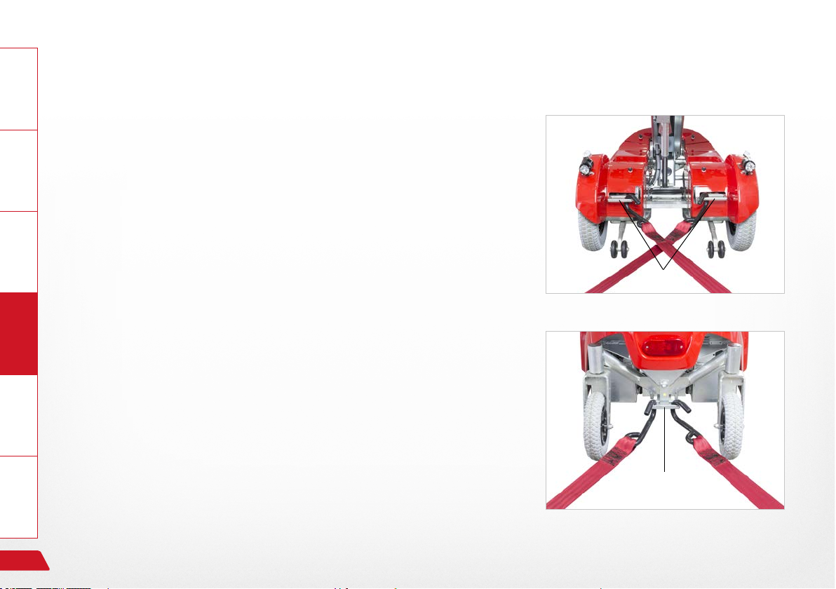
15.2 Securing your electric wheelchair, lashing
General Information Prepare Operate Help Technology
To prevent slippage, the electric wheelchair must be rmly secured or
lashed to the transport vehicle using lashings, hooks or straps. The
electric wheelchair must be secured in accordance with the
› DIN 75078 (Parts 1 and 2) standard for powered vehicles in order
for it to be conducted by persons with restricted mobility.
The electric wheelchair has the following lashing points.
› Front: two rigging eyelets
› Rear: one rigging eyelet
No other securing is required if your vehicle is equipped with a
PARAVAN docking station.
Fig. 43: Securing point at front
86
See Section "5.4.2 Available accessories"
Fig. 44: Securing point at rear
Controls
Page 87
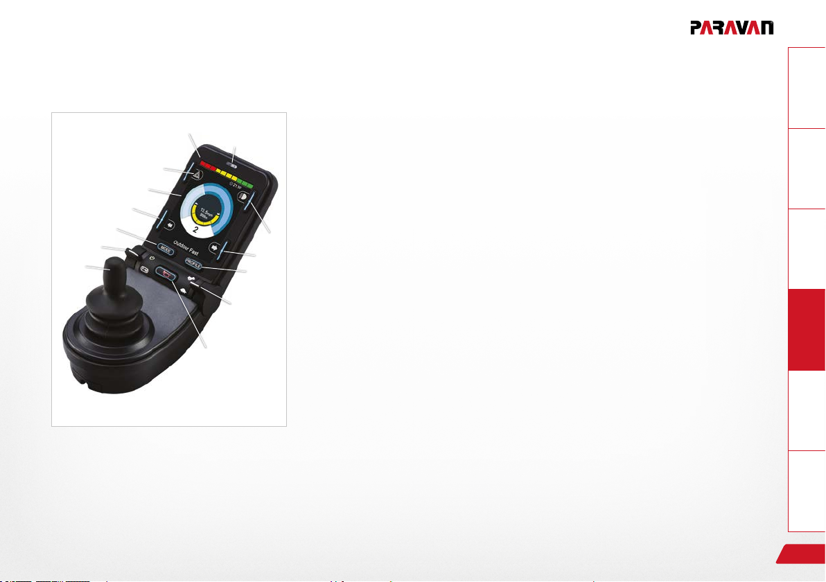
16. Controls
16.1 Control panel R-NET CJSM2
16.1.1 Overview of the control elements
⑫
⑩
④
②
⑤
①
⑦
⑧
Fig. 45: Control panel R-NET CJSM2
③
②
⑥
⑨
With the control panel (joystick) built into your power wheelchair, you
can control all of the power wheelchair's driving, steering and braking
processes. All additional functions which are equipped with displacement motors, such as the lifting arm and the sitting functions, must also
be operated via the control panel.
› “On/off” key ①
⑪
Selection of prole (movement levels)/mode (seat functions)
› “Direction indicator, right/left” keys ②
› LCD diagnostic LED brightness sensor ③
› Display ④ (colour)
› MODE key ⑤ for switching function – drive program/seat functions
› PROFILE key ⑥ (selection of movement levels)
› Joystick ⑦ (determines direction of travel)
› “Horn” key ⑧
› Function key ⑨ for selecting/drilling down to movement levels
› “Hazard lights” key ⑩
› “Light” key ⑪
› Charging status indicator for storage battery ⑫
GeneralInformationPrepareOperateHelpTechnology
Controls
87
Page 88
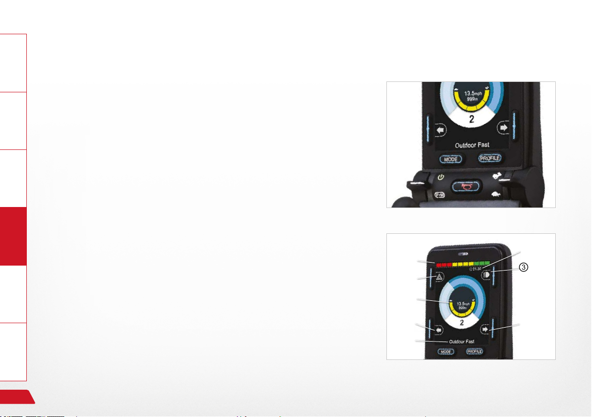
General Information Prepare Operate Help Technology
16.1.2 Status display
The function keys are used to select the specic functions displayed in
the assigned elds on the display.
Symbols of the status indicator:
› Charging status of the storage batteries ①
› Direction indicator, left ②
› “On/off” light ③
› System status ④ (“tortoise” → speed control active)
› Direction indicator, right ⑤
› Time ⑥
› Hazard lights “on/off” ⑦
› Current seat function ⑧ / current driving profile
Symbols ② + ⑤ play an active part in the “hazard lights”
function!
Fig. 46: Function keys
①
⑦
④
②
⑧
⑥
③
⑤
88
Fig. 47: Status display
Controls
Page 89
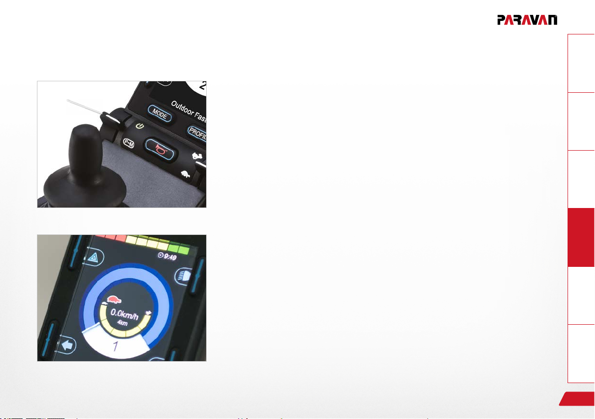
16.1.3 Start, switch off
①
Fig. 48: “On / off” key
GeneralInformationPrepareOperateHelpTechnology
Start
Push the “on/off” switch ① upwards.
› The status display briey ashes and the last selected function in
terms of movement level/seat function is shown.
› Press the switch ① downwards again to:
- Select movement levels 1 to 5.
- Then switch to the seat functions.
Switch off
Push the “on/off” switch ① upwards.
› The power wheelchair switches itself off (assuming it is already swit-
ched on).
Fig. 49: Speed control (tortoise) active
Controls
89
Page 90
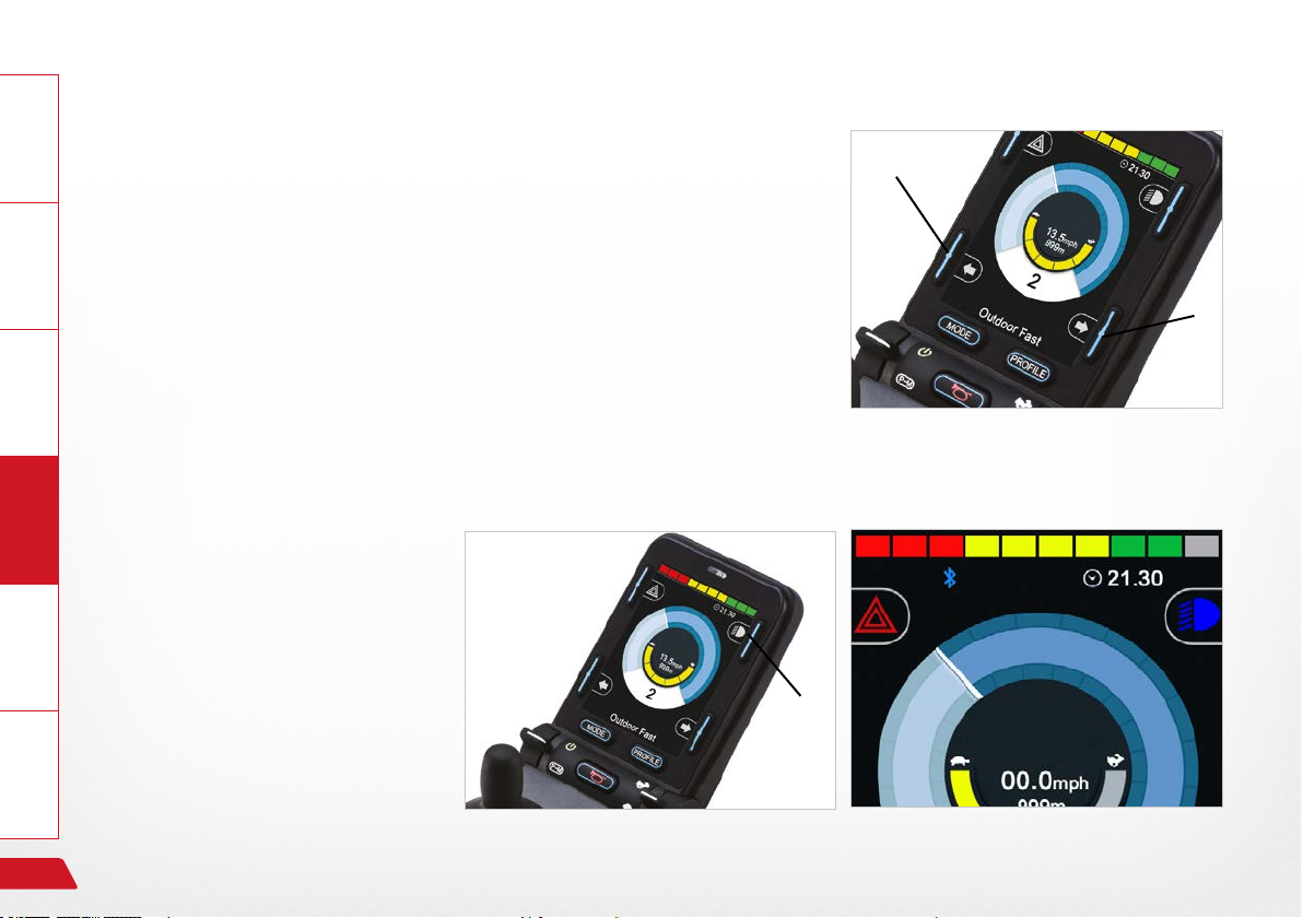
General Information Prepare Operate Help Technology
16.1.4 Switch direction indicator on and off
Press key ① or ② for the respective direction indicator, left or right.
› The selected direction indicator will ash.
› Press once more → direction indicator switches off.
16.1.5 Switch light on and off
Press the key for the “light
on” function.
The lighting installation switches itself on and the light
symbol lights up blue.
Fig. 52: Turn signal right / left
Press once more:
→ Light off
90
Fig. 50: Light symbol (colour)Fig. 51: Light on and off
Controls
Page 91
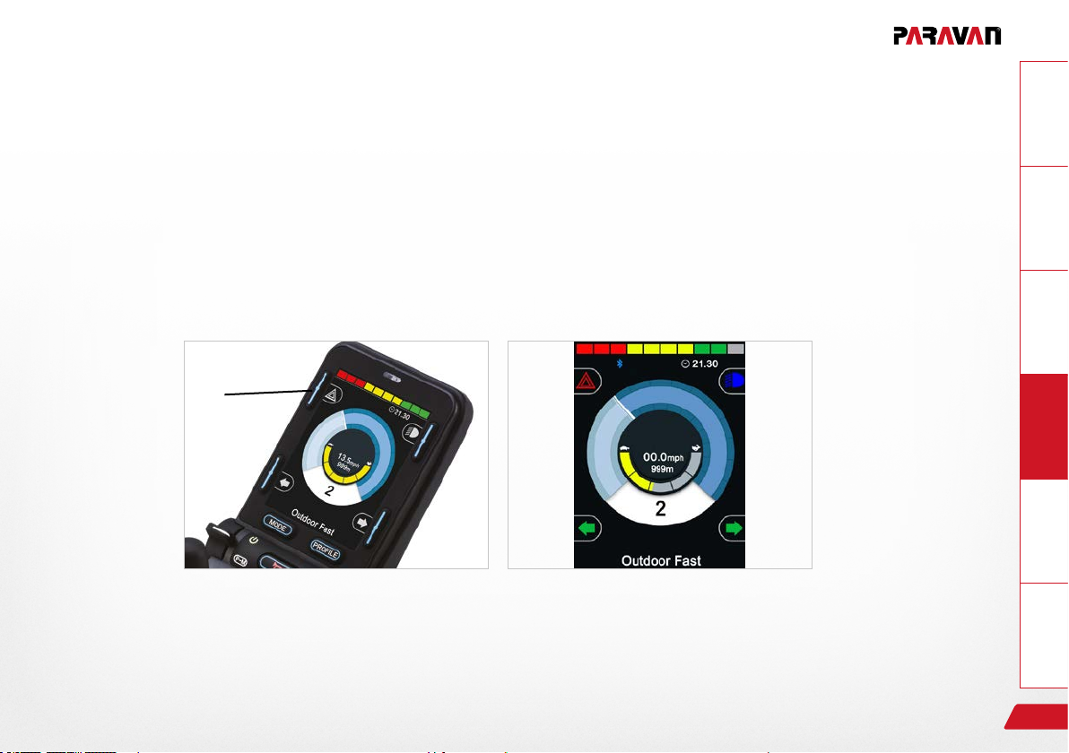
16.1.6 Switch hazard lights on and off
Press the “hazard lights” key for the “hazard lights on” function.
› The hazard lights switch themselves on, while the hazard lights symbol ashes red and
both direction of travel symbols ash green.
› Press the key again → the hazard lights/hazard lights symbol switch themselves off.
GeneralInformationPrepareOperateHelpTechnology
Controls
Fig. 54: Hazard lights on / off
Fig. 53: Symbols (colour)
91
Page 92
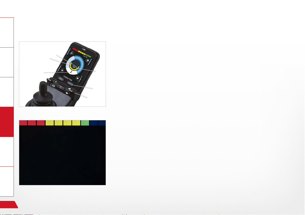
General Information Prepare Operate Help Technology
16.1.7 Driving functions overview
⑤
②
①
③
④
Fig. 55: Driving functions
Overview of the driving functions shown on the display of the control panel during driving, steering and braking actions of the power wheelchair.
› Selected drive program/movement level ①
⑥
› Respective setting (having drilled down) for the selected movement
level (1 to 5)Maximum speed in the selected drive program ②
› Key ③ (Prole) to switch to a higher or lower drive program (1 to 5)
› Key ④ to change speed in the drive program
› Display of the current speed (km/h) ⑤
› “Trip” display in kilometres ⑥
Display turns black when a charging device is connected.
› If the wheelchair is switched on, the charging status indicator is the
only thing shown.
› First connect the charging lead for the charging device at the joystick,
then plug the power cable for the charging device into the socket.
Fig. 56: Charging status indicator (driving function blocked)
92
If the power wheelchair is being charged via the charging socket
on the control panel, driving mode is automatically blocked.
Controls
Page 93
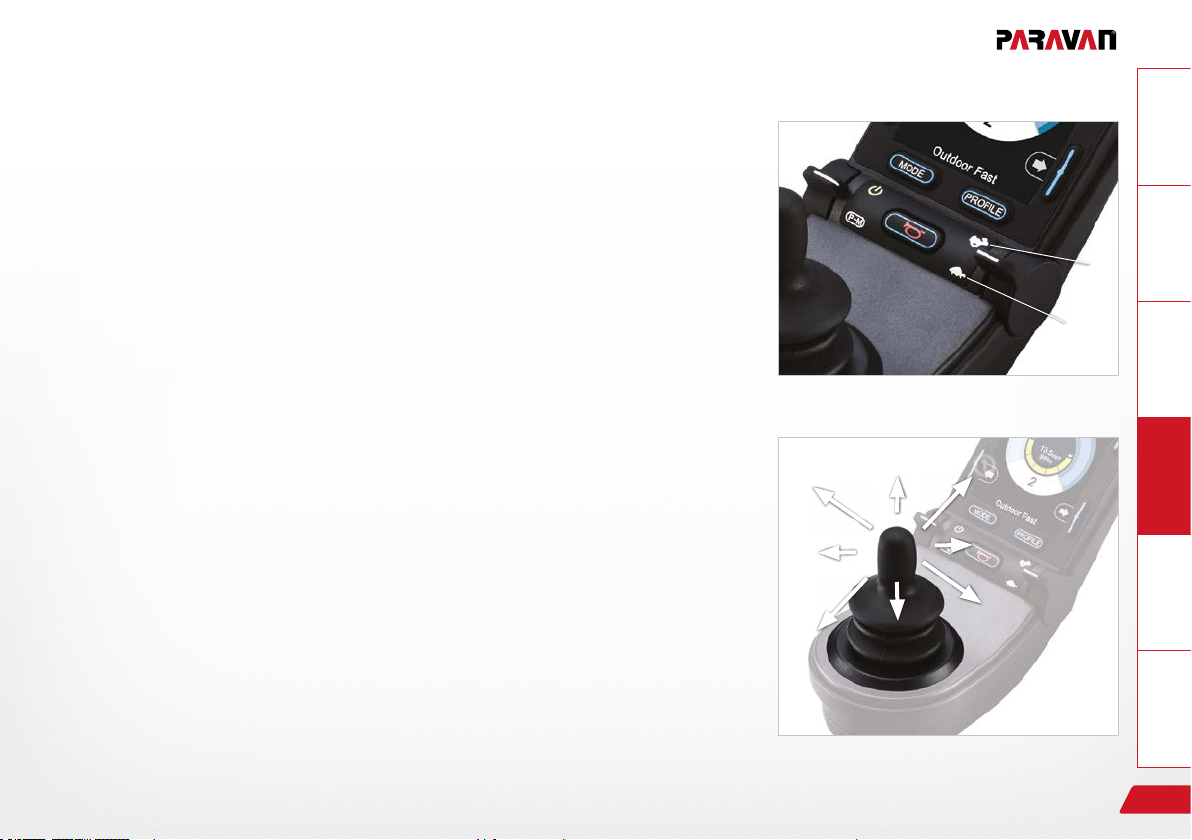
16.1.8 Select drive program, drive
The power wheelchair must be in driving mode.
› The last selected drive program is shown on the display (proles 1
to 5). Drive proles 1 to 5 are further divided into 5 levels once you
drill down.
GeneralInformationPrepareOperateHelpTechnology
①
Press the switch upwards ① or downwards ② to switch to a higher or
lower sub-level.
› The selected drive program and sub-level will appear on the display.
Push the joystick in the direction in which you wish to travel.
› The power wheelchair moves in the selected direction.
①Move forwards
② Turn to the right
③ Move backwards
④ Turn to the left
See section “3 Safety notes”
Controls
Fig. 57: Select drive program
④
③
Fig. 58: Joystick travelling direction
①
②
②
93
Page 94

General Information Prepare Operate Help Technology
16.1.9 Electrical seat adjustment
Fig. 59: Display of seat functions
Use the MODE key to switch from the drive program to the seat functions. Select the desired seat function by moving the joystick “← left/right
→”.
› The adjustment functions menu will appear on the display.
Only the released or available functions can be selected.
To make the desired setting:
adjust the seat, seat position, lifting of seat, backrest, tilting of seat, ang-
le for legs, legroom or electric footrest via the joystick (by moving it
forwards or backwards).
Switch back to the drive program with the prole key.
› The power wheelchair is ready to drive.
See section “3 Safety notes”
94
Controls
Page 95

16.1.10 Set time/date
Press and hold the “hazard lights” key to access the “Settings” menu.
› The special functions menu will appear on the display.
Move the joystick → left/right to access the options “year, month, date,
day of the week, hours and minutes”. Select the desired option by moving the joystick “← left/right →”.
Move the joystick “↑up/down↓” to select exactly the setting you want.
To save and quit the menu, go to “Quit” and close it by moving the
joystick “↑up/down↓”.
GeneralInformationPrepareOperateHelpTechnology
Fig. 60: “Set time” function menu
Controls
Fig. 61: Setting the time and date
95
Page 96

General Information Prepare Operate Help Technology
16.1.11 Show/hide clock, congure 12h/24h display
Select the program function:
› Press and hold the “hazard lights” key.
› The “Settings” menu appears.
› Use the joystick to select “Set time”. Move the joystick “← left/right
→”.
› Select “12h/24h display” or “Off” by moving the joystick “← left/right
→”.
› To save → quit the program. Move the joystick “← left/right →”.
Fig. 62: Set clock to visible/invisible
96
Controls
Page 97

16.1.12 Adjust display brightness
Select the program function:
› Press and hold the “hazard lights” key.
› Select “Back lighting” from the settings.
› Select the intensity of the lighting (0 to 100% in 10% stages) by mo-
ving the joystick “← left/right→”.
› To save → quit the menu.
16.1.13 Adjust display brightness, automatic
The display brightness is automatically adjusted to lighting
conditions by the factory. Menus may be arranged slightly differently, depending on the software version.
Select the program function:
› Press and hold the “hazard lights” key.
› Select “Auto Backlight” from the settings.
› Select “On/Off” by moving the joystick “← left/right→”.
› To save, quit the menu.
GeneralInformationPrepareOperateHelpTechnology
Fig. 64: Setting the display brightness
Fig. 63: Autom. display brightness
Controls
97
Page 98
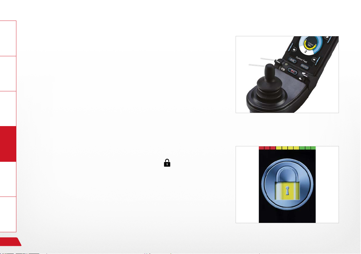
General Information Prepare Operate Help Technology
16.1.14 Block the controls (with the wheelchair switched on)
› Turn the controls on and press and hold the ON/OFF button ① until
you hear a beeping sound
› Move the joystick ② forwards until you hear a beeping sound
› Move the joystick ② backwards until you hear a beeping sound
16.1.15 Release the controls (with the wheelchair switched off)
› Switch on → and a “padlock symbol” appears
› Move the joystick ② forwards until you hear a beeping sound
› Move the joystick ② backwards until you hear a beeping sound
› The “Functions” menu is now available – the last function selected
is shown.
.
①
②
Fig. 66: Turn signal right / left
98
Fig. 65: Lock symbol
Controls
Page 99
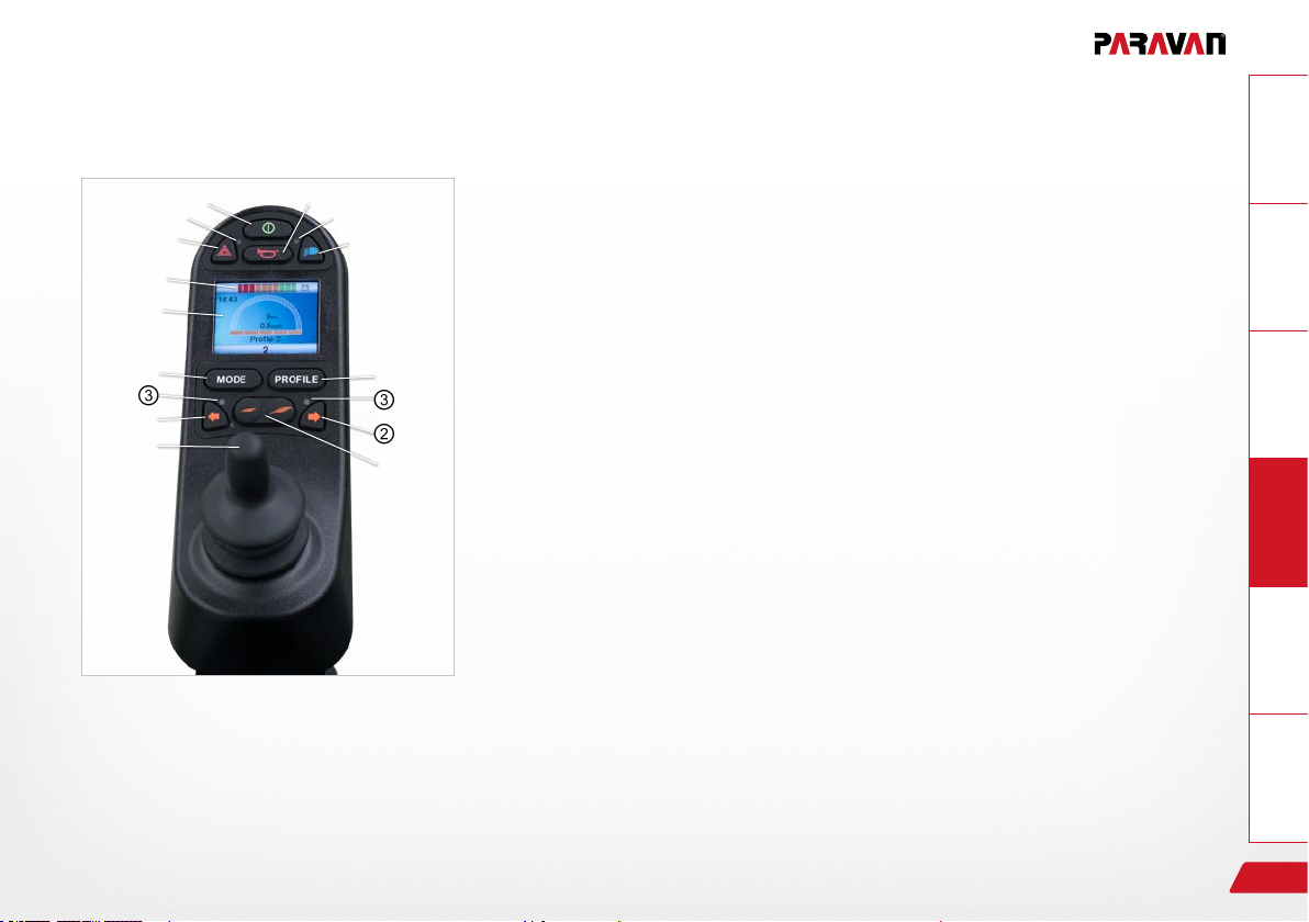
16.2 Control panel R-NET CJSM-L
16.2.1 Overview of the control elements
①
③
⑩
⑫
④
⑤
③
②
⑦
Fig. 67: Control panel R-NET CJSM-L
⑧
③
⑪
⑥
③
②
⑨
With the control panel (joystick) built into your power wheelchair, you
can control all of the power wheelchair's driving, steering and braking
processes. All additional functions which are equipped with displacement motors, such as the lifting arm and the sitting functions, must also
be operated via the control panel.
› “On/off” key ①
› “Direction indicator, right/left” keys ②
› Display showing the signal currently active (light, indicator) ③
› Display ④ (colour)
› MODE key ⑤ for switching function – drive program/seat function
› PROFILE key ⑥ (selection of movement levels)
› Joystick ⑦
› “Horn” key ⑧
› Function key ⑨ for selecting/drilling down to movement levels
› “Hazard lights” key ⑩
› “Light” key ⑪
› Charging status indicator for storage battery ⑫
GeneralInformationPrepareOperateHelpTechnology
Controls
99
Page 100
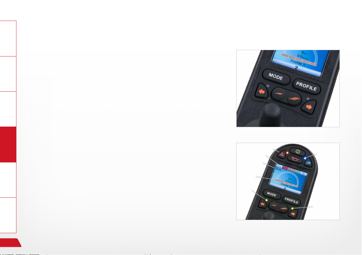
General Information Prepare Operate Help Technology
16.2.2 Status display
The function keys are used to select the specic functions displayed in
the assigned elds on the display.
Symbols of the status indicator:
› Charging status of the storage batteries ①
› Direction indicator, left ②
› “On” light ③
› System status ④ (“tortoise” → speed control)
› Direction indicator, right ⑤
› Time ⑥
› Hazard lights ⑦
Symbols ② + ⑤ play an active part in the “hazard lights”
function!
Fig. 68: Function keys
⑦
①
⑥
④
②
③
100
⑤
Fig. 69: Status display
Controls
 Loading...