

Page 1
O W N E R ' S M A N U A L
Zamp / Zone Amplifier
Congratulations on your purchase of this precision audio component and thank you for your selection of
Parasound. We designed the ZAMP for use in a wide variety of custom applications including multi-room
installations. The Zamp’s fully complementary discrete high-current design make it capable of driving
complex loudspeaker loads with ease.
Please take a few moments to read these instructions thoroughly so you may fully take advantage of the
versatility of your new Parasound amplifier.
p/Zone Am
er
w
o
P
Zam
plifier
n
uto O
resent
P
C
A
A
Unpacking and Placement
Carefully unpack your ZAMP and its detachable AC cord. Be sure to inspect the unit for any possible
shipping damage. If you notice any, contact your Parasound Dealer immediately. Be sure to save your
packing cartons and the packing inserts for future transport and always pack the inner carton into a protective
outer carton before shipment.
Keep your Parasound Zamp out of direct sunlight and away from windows. Locate it away from heat sources
such as hot air ducts or radiators. Be sure to allow plenty of ventilation if you are installing the Zamp within
an equipment cabinet.
Before you proceed, find the serial number located on the rear panel of your amplifier and record it here
for reference:
Serial #____________________ Date of Purchase____________________
Page 2

IMPORTANT SAFETY INSTRUCTIONS
The lightning flash with the arrowhead symbol within an equilateral triangle is intended to alert the user to the
presence of “dangerous voltage” within the product’s enclosure that may constitute a risk of electric shock.
The exclamation point within an equilateral triangle is intended to alert the user to the presence of important operating
and maintenance instructions in the literature accompanying the product.
TO REDUCE THE RISK OF ELECTRIC SHOCK, DO NOT REMOVE COVER. NO USER-SERVICEABLE PARTS
INSIDE. REFER SERVICING TO QUALIFIED SERVICE PERSONNEL
1. Read Instructions — Read all the safety and operating instructions before operating this product.
2. Retain Instructions — Retain safety and operating instructions for future reference.
3. Heed Warnings — Adhere to all warnings on the product and in the operating instructions.
4. Follow Instructions — Follow all operating and use instructions.
5. Cleaning — Unplug this product from the wall outlet before cleaning. Use a damp cloth for cleaning.
6. Attachments — Do not use attachments not recommended by the product manufacturer; they may cause hazards.
7. Water and Moisture — Do not use this product near water.
8. Accessories — Do not place this product on an unstable cart or stand. The product may fall causing bodily injury and
damage to the product.
9. A product and cart combination should be moved with care. Quick stops, excessive force, and uneven surfaces may
cause the product and cart combination to overturn.
10. Ventilation — Slots and openings in the cabinet are provided for ventilation and to ensure reliable operation of the
product and to protect it from overheating. These openings must not be blocked or covered. This product should not
be placed in a built-in installation such as a bookcase or rack unless proper ventilation is provided.
11. Power Sources — Operate this product only from the type of power source indicated on the marking label. If you are
not sure of the type of power supply to your home, consult your dealer or local power company. This product is
equipped with a three-wire grounding type plug. This plug will only fit into a grounding type power outlet. If you are
unable to insert the plug into the outlet, contact your electrician to replace your obsolete outlet. Do not defeat the safety
purpose of the grounding type plug.
12. Power Cord Protection — Power supply cords should be routed so that they are not likely to be walked on or pinched
by items placed upon or against them.
13. Lightning— For added protection for this product during a lightning storm, or when it is left unattended and unused for
long periods of time, unplug it from the wall outlet. This will prevent damage to the product due to lightning and power
line surges.
14. Overloading — Do not overload wall outlets or extension cords. This can result in a risk of fire or electric shock.
15. Object and Liquid Entry - Never push objects of any kind into this product through openings; they may touch
dangerous voltage points or short out parts that could result in a fire or electric shock.
16. Servicing — Do not attempt to service this product yourself. Opening or removing covers may expose you to
dangerous voltage or other hazards. Refer all servicing to qualified service personnel.
17. Damage Requiring Service — Unplug this product from the wall outlet and refer servicing to qualified service
personnel under the following conditions: a) When the power-supply cord or plug is damaged. b) If liquid has been
spilled, or objects have fallen into the product. c) If the product has been exposed to rain or water. d) If the product does
not operate normally by following the operating instructions. e) If the product has been dropped or damaged in any way.
f) When the product exhibits a distinct change in performance.
18. Replacement Parts — When replacement parts are required, be sure the service technician has used replacement parts
specified by the manufacturer or have the same characteristics as the original part. Unauthorized substitutions may result
in fire, electric shock, or other hazards.
19. Safety Check — Upon completion of any service or repairs to this product, ask the service technician to perform safety
checks to determine that the product is in proper operating condition.
20. Wall or Ceiling Mounting — Mount the product to a wall or ceiling only as recommended.
21. Heat — The product should be situated away from heat sources such as radiators, heat registers, stoves, or other
products (including amplifiers) that produce heat
-2-
Page 3
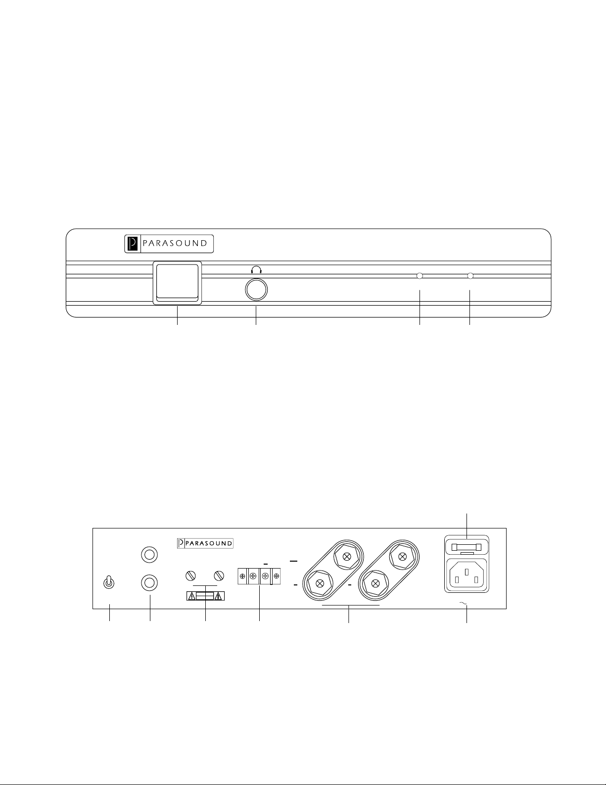
Zamp Front and Rear Panel Drawings
Zamp/Zone Amplifier
AC Present Auto On
Stereo
Mono
Bridge
Headphone JackPower Switch AC Present
Indicator
Auto On
Indicator
Zamp Front Panel
Fuse Holder
Zamp/Zone Amplifier
L
R
Input
Level
RL
CAUTION
RISK OF ELECTRIC SHOCK
DO NOT OPEN
120 Vac/60 Hz 120 W
5-12V DC Trigger
+
Parasound Products, Inc.
San Francisco, CA USA
++
R
L
Power Consumption: 120W
120V 60HzAC
Bridge
Switch
Input
Jacks
Level
Controls
DC Trigger 5-Way
Binding Posts
Zamp Rear Panel
-3-
AC Receptacle
Page 4

Making Connections to your ZAMP
Refer to Drawing on Page 3
When making connections, make sure there is no strain or tension on input leads or speaker wires that could
cause them to pull loose.
AC Line Connection
Before you attach the AC cord, make sure the ZAMP power switch is in its off position. The ZAMP includes
a detachable audiophile-grade AC cord. We recommend that you use only this cord and try to make direct
connection to the AC wall outlet.
Input Connections
Use the right and left channel RCA jacks for stereo operation. For bridged mono operation, use only the right
channel input jack and leave the left channel jack disconnected.
Speaker Connections — General Recommendations
You may use 4 Ω - 8 Ω rated speakers for stereo operation. We do not recommend lower impedance loads,
because they may cause overheating and activate one of the protection circuits. The speaker terminals of the
ZAMP will accept 1/4" spade lugs, dual or single-banana plugs or bare wire up to 12 AWG. For best results
you should never use speaker wire thinner than 16 AWG. If you use bare wire without plugs, make sure you
strip off only enough insulation so the bared wire fits through the hole that runs sideways through the
terminal’s metal shaft. Before inserting the wire, twist all its strands tightly to prevent strays that could cause
a short circuit between + and - terminals. You may want to “tin” the stripped wire with solder to prevent
it from fraying.
Polarity
It is important to observe correct speaker polarity. One side of the speaker wire will have some sort of mark
such as printing, a raised ridge on the insulation or a different color conductor. This lets you know which wire
to connect to the + and which to the - speaker terminals so you can make the same connections to the 5 way
binding posts on the Zamp.
Mono Bridge Switch
Set the bridge switch to normal Stereo (up) or Mono Bridged (down) operation as marked on the rear panel.
Make sure the power is off to the ZAMP before changing this switch position. If you accidentally leave the
Mono Bridge switch in the Mono position for normal stereo listening, you will find stereo output will be very
weak and distorted.
Bridged Mono Operation
When mono bridging your Zamp, do not connect a speaker with an impedance lower than 8 Ω because in the
bridged mode, each channel effectively “sees” only half of the speaker’s actual impedance. With an 8 Ω
speaker means that the load for each channel is 4 Ω. For a 4 Ω speaker, the impedance would be 2 Ω per channel
which is too demanding on the amplifier.
In the bridged mode, connect your speaker to the left red + terminal and the right red + terminal. In the bridged
mode the right channel’s red terminal becomes positive and the left channel’s red terminal becomes negative.
Do not use either of the black terminals in the bridged mode.
-4-
Page 5

Operating Your ZAMP
Refer to Drawing on Page 3
Power Switch
Manual Turn On
Press the upper side to turn the unit on manually; press the lower side to turn the unit off.
Automatic Turn On
When the power switch is in the off position, the power amplifier can be turned on with external DC voltage
applied to the DC trigger connector on the rear panel. If you want to turn on your ZAMP a DC trigger, leave
the power switch in the Off (down) position.
DC Trigger Connection
This connector provides a way to trigger your amplifier on with an external DC voltage source ranging from
+ 5 Vdc to +12 Vdc at 25 milliamps. With the main power switch on the Off (down) position, the amplifier
can be turned on with voltage from any external DC source such as the +12 Vdc trigger from the Parasound
P/SP-1500. Once the Zamp has been triggered on with a DC trigger, the green Auto On LED illuminates.
Immediately after the DC trigger voltage is removed, the Zamp will automatically turn itself off and the Auto
On LED will no longer illuminate.
Level Controls
Each channel has a separate input level control. If your preamplifier has relatively high gain, it may be
necessary to reduce the input level control settings on the ZAMP. We located the level controls on its rear
panel, so you can set them once and leave them alone.
Headphone Jack
The built in headphone jack drives any headphones with an impedance of 8 Ω or higher. The ZAMP must
be triggered on with an audio signal or DC trigger before it will pass a signal to the headphone jack. The output
to the speakers is muted when you plug headphones into the Zamp.
Maintaining Your ZAMP
The ZAMP requires no periodic maintenance and has no user serviceable parts inside. Do not remove the
top cover to avoid risk of electric shock. To keep it clean use only a soft cloth and never use any solvents
or abrasives. Fingerprints may be removed with a soft cloth moistened with clean water or window cleaner.
In Case of Trouble
If you suspect a problem with this unit, contact your authorized Parasound Dealer or Installer, or call
Parasound Technical Services. We may be able to suggest diagnostic tests you can easily perform that may
save you a lot of trouble. If we determine that your ZAMP should be returned to Parasound or an Authorized
Warranty Center for inspection and possible servicing, call for the location of a Warranty Center near you.
If you choose to send it to Parasound, you must obtain a Return Authorization number. Before shipping,
repack the unit in its original packing plus an additional outer cardboard carton for extra protection during
transit. After we repair the unit under warranty, we will return the unit to you freight prepaid.
Power Fuse
The ZAMP has an external fuse located within the AC inlet on the rear panel. This fuse may blow as a result
of an internal fault condition to protect the unit from possible damage to internal parts. Never replace this
fuse with a larger value. Substitution of a larger fuse may create serious stress or damage to internal parts
and will void your warranty.
-5-
Page 6

Parasound ZAMP Specifications
Continuous Power Output - Stereo
30 watts RMS x 2, 20 Hz-20 kHz, 8 Ω, both channels driven
45 watts RMS x 2, 20 Hz-20 kHz, 4 Ω, both channels driven
Continuous Power Output - Mono
90 watts RMS, 20 Hz-20 kHz, 8 Ω Minimum Impedance
Current Capacity
10 amps peak per channel
Slew Rate
> 90 V/µsecond
Frequency Response
5 Hz-100 kHz, +0/-3 dB at 1 watt
Total Harmonic Distortion
< 0.03 % at full power; < 0.01 % typical levels
IM Distortion
< 0.03 %
TIM
Unmeasureable
Dynamic Headroom
> 1.5 dB
Interchannel Crosstalk
> 80 dB at 1 kHz
> 60 dB at 20 kHz
Input Impedance
33 kΩ
Input Sensitivity
1 V
S/N Ratio
> 100 dB, input shorted, IHF A-weighted
Damping Factor
> 400 at 20 Hz
Dimensions
9 1/2" W x 1 3/4" H (2" with feet) x 7" D
Weight
9 lb net
-6-
Page 7

Parasound Products, Inc. 950 Battery Street, San Francisco, CA 94111
415-397-7100 / FAX 415-397-0144 www.parasound.com
-7-
© 1998 Parasound Products, Inc. Revision C
 Loading...