

Page 1
O W N E R ' S M A N U A L
S/PS-140 Loudspeaker Selector
Congratulations on your purchase of this precision component and thank you for your selection of
Parasound. We designed your Parasound S/PS-140 to switch up to four pair of speakers with the output
of one amplifier. The S/PS-140 also has switchable protection to prevent amplifier overload.
S/PS-140 Loudspeaker Selector
1
2
3
4
Protect
Product Overview
In many home audio systems, it is desirable to be able to listen to music in more than one area. For
example, you may have pairs of speakers in the living room, dining room, kitchen and patio that you
want to drive with a single amplifier. The S/PS-140 gives you the capability of switching on any or all
four pairs of these speakers depending on where you want to hear music.
Unpacking the S/PS-140
Unpack your S/PS-140 and save the carton and packing inserts for safe transport in case you move or in
case the unit should ever require repair. You should find the following items within the packing carton:
〈 The S/PS-140
〈 20 Gold Plated Spade Lugs with Insulators
〈 This manual
Location of your S/PS-140
Place your S/PS-140 in a location which lends convenient access to the speaker switches and try to place
the S/PS-140 near the power amplifier so you can keep the speaker wires relatively short.
Rack Mounting your S/PS-140
The S/PS-140 will occupy a single rack space in a standard 19" equipment rack when you fasten it to
another half width product such as the Zamp, or R/EQ-150. If you plan to rack mount the two half width
products together, call Parasound Technical Services to order the necessary rack mounting hardware.
-1-
Page 2
Making Connections to your S/PS-140
Connections to
Power Amplifier
+
R
ININ
L
+
+
1
R
L
+
+
R
Connections to
Loudspeakers
2
L
S/PS-140
Parasound Products, Inc. San Francisco, CA USA
+
+
Loudspeaker Selector
3
R
L
+
+
4
R
L
+
Speaker Wire Polarity
When you connect the various speaker wires to your S/PS-140, you will notice that one side of the two
conductor speaker wire will have some sort of mark: either printing, a raised ridge on the insulation, or a
different color of conductor. The marked insulation or copper colored wire usually indicates the positive
conductor. This demarkation lets you know which wire is connected to the positive and which to the
negative speaker terminals so you can do exactly the same to the power amplifier's red (+) and black (-)
binding posts.
Connecting Speaker Wires Using 1/4" Spade Lugs
For ease of installation, we recommend that you use the gold-plated 1/4" spade lugs provided with your
S/PS-140 for terminating all of your speaker connections. These crimp-on connectors will accept wire
up to AWG 10. Also included are red and black insulation "boots" to insulate the speaker wire and to
indicate proper polarity (see below).
Crimping Spade Lugs Onto the Speaker Wires
1. Strip about 1/4" of insulation from the speaker wire
2. Slip the insulation boot over the speaker wire
3. Twist all its strands tightly and insert the wire into the spade lug
4. Use a crimping tool to crimp the spade lug onto the speaker wire
5. Slip the insulation boot over the spade lug
6. Once you have inserted the wire into the terminal, tighten the screw with a phillips or flat blade
screwdriver.
Connecting Speaker Wires Using Bare Wire
If you wish, you may connect bare wire up to AWG 12 to the terminal strip on the S/PS-140. Make sure
you remove only enough insulation so the wire can fit under the square washer of the terminal strip.
Before inserting the wire, twist all its strands tightly to prevent strays that could cause a short circuit.
(You may want to "tin" the stripped wire with solder to prevent it from fraying and oxidizing.) Once you
have inserted the wire into the terminal, tighten the screw with a phillips or flat blade screwdriver.
-2-
Page 3

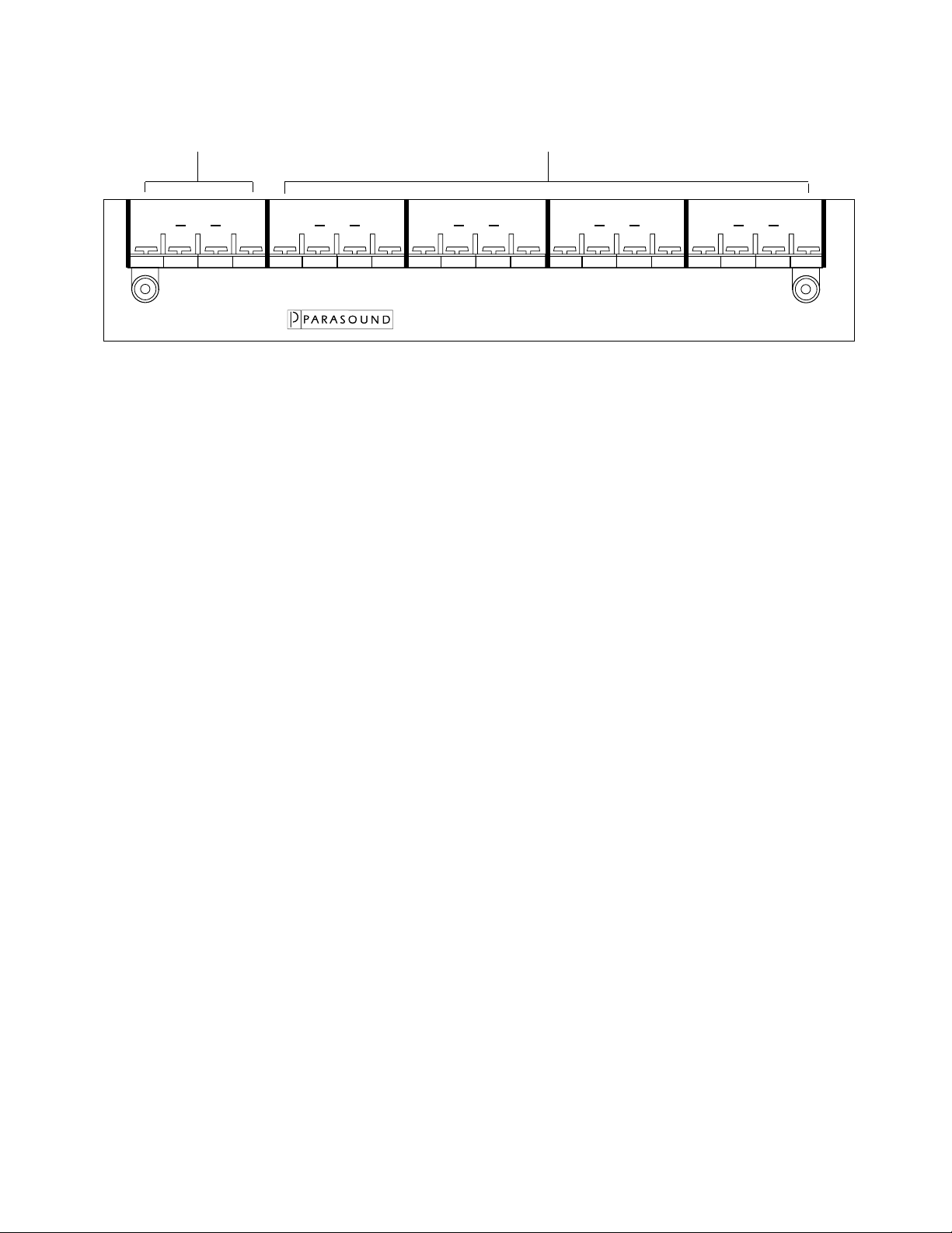
Operating Your S/PS-140
S/PS-140 Loudspeaker
21
Loudspeaker Selectors Amplifier Protection
Protect43
Loudspeaker Selector Switches
Once you have connected up to four pairs of loudspeakers to the S/PS-140, you can turn on any pair by
simply pressing the designated selector switch for the speakers you want to hear.
Speaker Impedances and the Amplifier Protection Switch
When switching on multiple pairs of loudspeakers, you need to be aware of your amplifier's capability of
safely driving all of the selected speakers. Most power amplifiers can easily drive impedances as low as
4 Ω per channel. However, as you try to drive impedances below 4 Ω, the amplifier may go into
protection or even fail. You should use the protection switch whenever you connect any more than two
pairs of 8 Ω loudspeakers to your S/PS-140.
The speaker protection selector switches in a 60 watt non-inductive resistor bank that keeps the amplifier
from "seeing" impedances below 4 Ω. This provides protection for amplifiers with up to 250 watts per
channel from damage when driving multiple pairs of loudspeakers. With the protection switch engaged,
you will experience a slight reduction volume from the loudspeakers.
S/PS-140 Specifications
Protection Wattage: Internal 60 watt non-inductive resistors protect amplifiers up to 250 watts per
channel.
Dimensions: 9 1/2" W x 1 3/4" H (2" with feet) x 7"
Net Weight: 2 1/2 lb.
Specifications subject to change or improvement without notice
-3-
Page 4

Parasound Limited Warranty (USA only)
Parasound Products, Inc. warrants products purchased from authorized Parasound Dealers and Custom
Installers to the original owner for two years from the date of purchase. In the event of a defect in
materials or workmanship, the product will be repaired promptly without charge. At Parasound’s
discretion, the product may be replaced with a new product of equal or superior value to the defective
product according to the condition that it was in received by Parasound.
The warranty excludes parts subject to normal wear such as fuses, laser pickups, or cosmetic parts.
The warranty also excludes damage resulting from abuse, shipping damages, and failure to use products
within specifications or instructions.
The warranty is void in the event of an unauthorized repair or modification, or removal or defacing of
the serial number.
Dealer stock will be warranted to a maximum of 2 years from date of purchase.
In no case will Parasound accept warranty claims for any purchaser’s unit after 38 months from the date
of the original dealer’s purchase from Parasound.
For Returns: Call, write, or fax Parasound’s Technical Services Department. If it is decided that the
unit should be returned for inspection at Parasound, it must be packed in its original carton as well as an
additional outer carton. A Return Authorization (RA) number will be issued which must appear on the
outer carton. A note stating the nature of the defect should accompany the unit. Units that arrive with
evidence of mispacking (internal rattling, damaged carton) must be refused by Parasound.
Parasound Products, Inc. 950 Battery Street, San Francisco, CA 94111
415-397-7100 / FAX 415-397-0144
-4-
 Loading...