

Parasound HCA1206 User Manual
O W N E R ' S M A N U A L
HCA -1206 High Curre nt Mult i Ampli fie r
LUCASFILM
LUCASFILM
¤
®
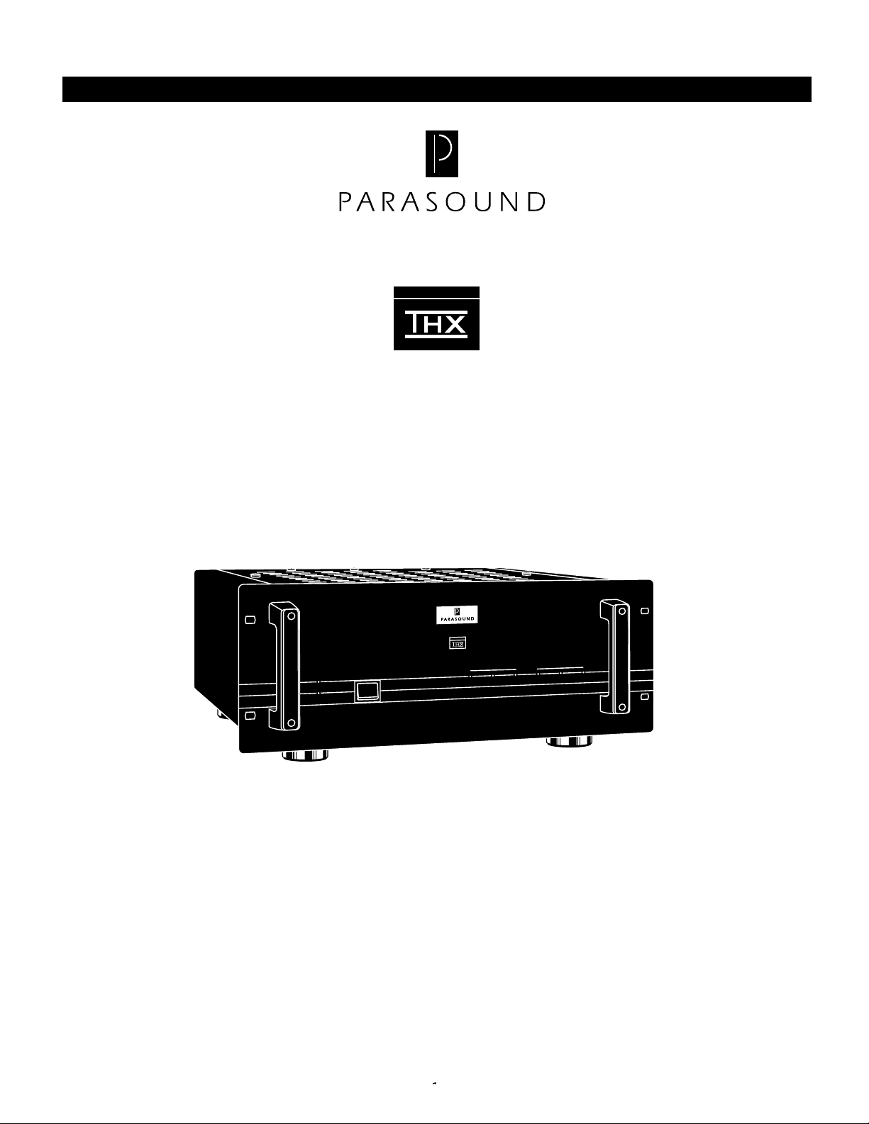
Congratulations on your purchase of this precision audio component and thank you for your selection of
Parasound. Your HCA-1206 was designed by renowned circuit designer John Curl to meet or surpass
the stringent standards required by Lucasfilm for use in THX Home Cinema systems. Each part within
your HCA-1206 has been painstakingly selected for optimum sound quality on even the most
challenging music and film soundtracks. Please take a few moments to read these instructions so you
may fully understand the capabilities of your new Parasound power amplifier.
ra
e
p
Operation
O
n
ta
Stand by
S
HCA-1206 High Current Multi Amplifier
r
e
w
o
P
Power
n
tio
y
b
d
LUCASFILMLUCASFILM
d
a
rlo
e
v
Overload
O
4
H
C
CH 4
3
H
C
CH 3
2
H
C
CH 2
1
H
C
CH 1
5
H
C
CH 5
5
H
C
CH 5
Unpacking Your HCA-1206
The HCA-1206 is packed in two strong cardboard cartons. To unpack the amplifier, open both cartons
and carefully remove the HCA-1206 from its inner carton. You may use its rear handles to facilitate
removal from the carton. Take care not to cut or scratch yourself on the exposed extruded metal
heatsinks on either side of the unit. Save your cartons and the packing inserts for safe transport in case
you move or if the unit ever requires shipping for repair. Due to the massive weight of the HCA-1206,
the inner white printed carton is not strong enough for safe shipping by itself. You absolutely must
place it into the additional outer over-carton before shipment.
The audiophile grade AC cord is packed separately in the carton. This is the only cord we recommend
for use with your HCA-1206. Please do not lose it. Before you proceed, find the serial number which is
located on the rear panel of your unit and record it here for future reference or in case of casualty loss or
theft: _____________
-1-

Placement of Your HCA-1206
Place your HCA-1206 away from heat sources such as hot air ducts or radiators. Make sure that your
cabinet or shelf can support its enormous weight. Always place your unit horizontally. Do not place your
unit directly on a carpet whose pile could interfere with air flow into its bottom vent openings or heat
sinks. If you place your HCA-1206 on the floor near your speakers, elevate it above the pile of the
carpet. If you stack your components, it is better to place your HCA-1206 alongside other components.
Rack Mounting Your HCA-1206
Your HCA-1206 can be mounted into a standard EIA 3 unit 19" rack. Make sure you select heavy duty
mounting bolts and nuts and use washers under the heads of the bolts to avoid scratching your amplifier’s
anodized front panel. Do not attempt to hold your unit in place yourself while you attach the bolts and
nuts. Have a strong helper support the unit as it is being attached to the rack. The heat generated by the
HCA-1206 may require a fan to assist air flow and if you have another component mounted directly
above it in the rack.
Ventilation Requirements for Your HCA-1206
Your Parasound power amplifier is designed to operate with high idling, or bias, current to reduce higherorder harmonic distortion. This bias optimization is characteristic of all Parasound power amplifiers and
is perfectly normal, but it results in noticeably warm operation even when no signal is present. While
many other amplifiers manufacturers have chosen to bias their amplifiers at a lower level to run cooler,
we bias our amplifiers so the output transistors are allowed to operate in a much more linear region.
Although the amplifier may run a little warmer than other amplifiers, we feel the resulting sonic
improvements are significant and justified.
However, to insure safe and reliable operation, it is very important that the amplifier has plenty of
ventilation to prevent overheating and automatic shut down from the thermal protection circuitry.
Please observe the following guidelines when installing your Parasound power amplifier:
1. If you are not using a fan, allow at least six inches on each side and above the amplifier, and
do not close off the front with a door or panel.
2. If you are enclosing the amplifier in an equipment cabinet, use a fan and draw in cool air or
exhaust warm air. In either case, two vent holes are required: one for intake and one for exhaust.
3. Do not place the amplifier on carpeting which will obstruct the air flow from the bottom of the
amplifier.
4. If you plan on stacking amplifiers, you must use a fan.
Minimum Impedance Precautions
You may connect loudspeakers with a 4 Ω or 8 Ω nominal impedance for unbridged operation. Your
HCA-1206 is capable of driving speakers with occasional impedance dips well below 2 Ω. However,
Lower nominal impedance loads are not recommended and may cause overheating.
The HCA-1206 is designed for a minimum 8 Ω nominal impedance for each speaker connected to
bridged channels 3+4 or 5+6. Use of lower impedance at high listening levels may cause overheating or
trigger one of the amplifier's protection circuits.
These restrictions result from the mathematics of the bridging circuitry. In the bridge mode each channel
of the amplifier functions for only the + or — half of the musical waveform. Thus, each channel "sees"
only half of the speaker’s impedance. Use of an 8 Ω speaker means that the load for each channel is
4 Ω. And for a 4 Ω speaker, it would result in only 2 Ω .
-2-
HCA-1206 Front and Rear Panel Controls
lifier
p
m
lti A
u
t M
rren
u
C
h
ig
6 H
0
2
-1
A
C
H
Power
Operation
Stand by
LUCASFILM
LU
SFILM
CA
Overload
CH 3
CH 2
CH 1
CH 5
CH 4
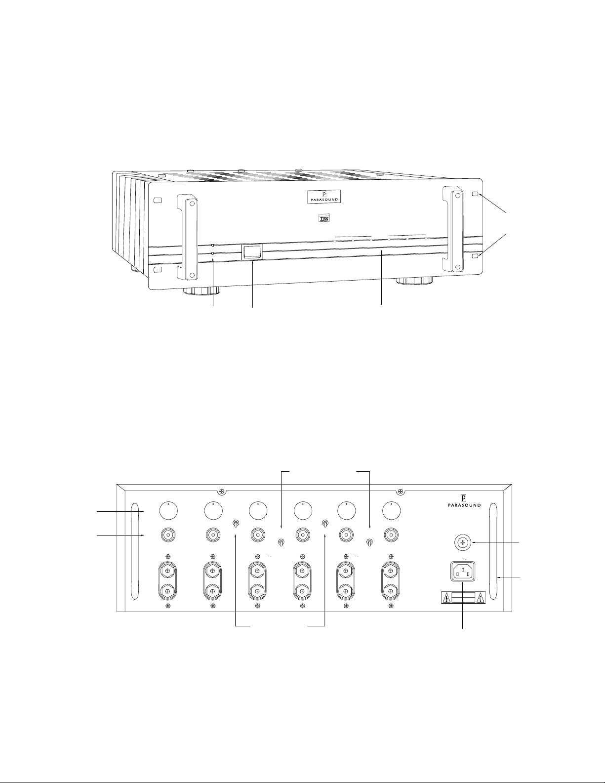
EIA Rack
Mount Holes
CH 5
Level Controls
Input Connectors
Standby/Operation
LEDs
Levels
Inputs
Non-
Bridgeable
Power Switch
Current Overload LEDs
Figure #1 HCA-1206 Front Panel Controls
Bridge Switches
CH 6CH 5CH 4CH 3CH 2CH 1
Loop 1/2-3/4
On
Off
Mono
Bridging
Separate CH 3, CH 4
Mono
Bridging
8 Ω Min
Loop 1/2-3/4
On
Off
+
Mono
Bridging
Separate CH 5, CH 6
Mono
Bridging
8 Ω Min
+
WARNING:
TO PREVENT FIRE OR SHOCK
HAZARD.DO NOT EXPOSE THIS
UNIT TO RAINOR MOISTURE.
CAUTION:
TO PREVENT ELECTRIC SHOCK,
DO NOTREMOVE COVER. NO USER
SERVICEABLEPARTS INSIDE. REFER
SERVICING TOQUALIFIED SERVICE
PERSONNEL.
HCA - 1206
High Current Multi-Amplifier
Parasound Products, Inc
San Francisco, CA U.S.A.
Fuse 15A
Power
AC 120V
60Hz
Power Consumption: 600 W
CAUTION
RISK OF ELECTRIC SHOCK
DO NOT OPEN
Main Fuse
Carry Handle
Input Looping
Switches
Figure #2 HCA-1206 Front Panel Controls
-3-
AC Cord Connector

Input Connections and Switch Settings for the HCA-1206
Refer to Figure #2
Six Channel Operation
The six channel mode of your HCA-1206 can power the six speakers required for a complete home
theater: Front left and right, surround left and right, center channel, and subwoofer. Connect each output
from your surround processor to the corresponding input connector of your HCA-1206.
If you are using your HCA-1206 in the six channel mode, we suggest the following progression of
channel priorities. This is an easy way to remember what you connected to each channel for setting
levels or troubleshooting:
Recommended Input Connections for Six Channel Operation
Use INPUTS 1 and 2 for your front left and right channels
Use INPUTS 3 and 4 for your left and surround right channels
Use INPUTS 5 for your center channel
Use INPUTS 6 for your passive subwoofer
Switch Settings for Six Channel Operation:
Leave LOOP 1/2 > 3/4 and LOOP 1/2 > 5/6 switches in their OFF positions and both MONO BRIDGE
switches in their SEPARATE positions.
Four and Five Channel Operation
In addition to six channel operation, you can use your HCA-1206 in a variety of other configurations
depending upon your needs. Below are examples of four and five channel operation.
Input Connections for Four Channel Operation
Use INPUTS 1 and 2 for your front left and right channels
Use INPUTS 3 and 4 bridged mono for your center channel
(Connect the center output of your processor to INPUT 4 only)
Use INPUTS 5 and 6 bridged mono for your subwoofer
(Connect the subwoofer output of your processor to INPUT 6 only.)
Use an additional amplifier for your surround channels
Switch Settings for Four Channel Operation:
Leave LOOP 1/2 > 3/4 and LOOP 1/2 > 5/6 switches in their OFF positions
Set the MONO BRIDGE switch for channel 3/4 in the MONO BRIDGING position
Set the MONO BRIDGE switch for channel 5/6 in the MONO BRIDGING position
Input Connections for Five Channel Operation
Use INPUTS 1 and 2 for your Front left and right channels
Use INPUTS 3 and 4 for your left and right surround channels
Use INPUTS 5 and 6 bridged mono for your center channel
(Connect the center output of your processor to INPUT 6 only)
Settings for Five Channel Operation:
Leave LOOP 1/2 > 3/4 and LOOP 1/2 > 5/6 switches in their OFF positions
Select the MONO BRIDGE switch for channel 3/4 in the SEPARATE position
Select the MONO BRIDGE switch for channel 5/6 in the MONO BRIDGING position
Use a powered subwoofer or an additional amplifier for a passive subwoofer
-4-
 Loading...