

Page 1

1
Hotwirer TDM SDSL Termination Units
Models 8775 and 8785
Installation Instructions
Document Number 8700-A2-GN15-20
February 2001
Product Documentation Online
Complete documentation for this product, including configuration options and cable pin
assignments, is available at www.paradyne.com. Select Library → Technical Manuals
→ Hotwire DSL & MVL Systems.
Select the following document:
8700-A2-GB25
Hotwire TDM SDSL Termination Units, Models 8775 and 8785, User’s Guide
For information about the DSLAM or MCC, select from the following documents:
8000-A2-GB22
Hotwire Management Communications Controller (MCC) Card, IP Conservative,
User’s Guide
8000-A2-GB29
Hotwire Management Communications Controller (MCC) Card
User’s Guide
8610-A2-GN10
Hotwire 8610 DSLAM Installation Instructions
8810-A2-GN11
Hotwire 8810 DSLAM Installation Instructions
8820-A2-GN10
Hotwire 8820 GranDSLAM Installation Instructions
To order a paper copy of a Paradyne document:
H Within the U.S.A., call 1-800-PARADYNE (1-800-727-2396)
H Outside the U.S.A., call 1-727-530-8623
Page 2

2
Hotwire TDM SDSL Termination Units
Hotwirer 8775 and 8785 TDM SDSL Termination Units are circuit card assemblies
comprising four Time Division Multiplexer Symmetric Digital Subscriber Line
(TDM SDSL) ports and four synchronous ports. When the Hotwire 87xx TDM SDSL
Termination Unit is used in a Hotwire 8600 or 8800 Series Digital Subscriber Line
Access Multiplexer (DSLAM), it transports up to 2048 kbps signals over traditional
twisted-pair telephone wiring.
Installation Overview
Installation and configuration of the Hotwire 87xx TDM SDSL Termination Unit
consists of:
H Installing the unit in the DSLAM.
H Connecting to the Data Terminal Equipment (DTE).
H Connecting to a Main Distribution Frame (MDF).
H Providing initial unit identity information or changing existing identity information.
H Configuring the unit using the Configuration Edit menus.
Before you install the unit, read the Important Safety Instructions in the appropriate
DSLAM manual.
Planning the Installation
Review the following list to help plan for the installation.
-
Obtain the applicable cables; refer to Cables You Need.
-
Make sure the Hotwire DSLAM is installed and power is supplied to the chassis.
-
After the unit is installed, there are configuration procedures that must be
performed before you can begin to use it. Refer to the User’s Guide if you require
detailed configuration procedures.
Page 3

3
Cables You Need
The following customer-provided cables are used with this product.
For the network connection:
H Plug-ended 50-position Telco cable for connection from the Hotwire DSLAM to the
Main Distribution Frame (MDF) or other demarcation point.
For the DTE connection, one of the following:
H V.35: 100-position plug-to-four MS34
(like Paradyne Feature No. 8700-F1-501)
H X.21: 100-position plug-to-four DB15
(like Paradyne Feature No. 8700-F1-502)
H RS-449: 100-position plug-to-four DB37
(like Paradyne Feature No. 8700-F1-503)
H EIA-530-A: 100-position plug-to-four DB25
(like Paradyne Feature No. 8700-F1-504)
H V.35: 100-position plug-to-four MS34 crossover
(like Paradyne Feature No. 8700-F1-506)
H EIA-530-A: 100-position plug-to-four DB25 crossover
(like Paradyne Feature No. 8700-F1-507)
For more information refer to Cables and Pin Assignments in the User’s Guide, and the
appropriate DSLAM installation document.
Page 4
496-15149
4
Installing TDM SDSL Cards
A Hotwire TDM SDSL Termination Unit can be installed, removed, and replaced without
disrupting service to other cards in the chassis.
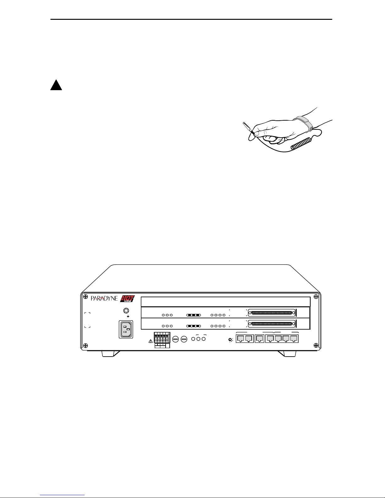
!
HANDLING PRECAUTIONS FOR STATIC-SENSITIVE DEVICES
This product is designed to protect sensitive components from
damage due to electrostatic discharge (ESD) during normal
operation. When performing installation procedures,
however, take proper static control precautions to
prevent damage to equipment. If you are not sure
of the proper static control precautions, contact
your nearest sales or service representative.
" Procedure
To install the unit:
1. Determine in which slot the unit will be installed. Verify that cards in adjacent slots
have been fastened using the screws at each end of their front panels.
2. Remove the filler plate from the installation slot.
3. Insert the unit into the DSLAM:
— For a Hotwire 8600 Series DSLAM – Hold the unit horizontally, with the
component side facing up, and insert it into the left and right card guides.
99-16311-02
TM
TM
STACK
POSITION
2
3
6
5
4
1
AC
INPUT
1
2
3
ESDESD
48VDC CLASS 2
OR LIMITED
PWR SOURCE
48VARTN
ABB
A
B
DC FUSES
T4A, MIN. 48V
PWR
A
ALM
FAN
B
OUTIN SERIAL
ALM INTF
MCP/1
2
3
MCP/
DSL
MANAGEMENT
10 BASE T
8610
4
M/HDSL
8785
SYSTEM
OK
Alrm
Test
1
2
3
1
2
3
SYNC PORT
DSL PORT
LINK-UP
4
4
M/HDSL
8785
SYSTEM
OK
Alrm
Test
1
2
3
1
2
3
SYNC PORT
DSL PORT
LINK-UP
4
Page 5

5
— For a Hotwire 8800 Series DSLAM – Hold the unit vertically, with the
component side facing right, and insert it into the top and bottom card guides.
ALARMS
Major MinorFanBA
POWER
MCC
S
Y
S
T
E
M
O
K
A
lm
T
e
s
t
ETHE
RN
ET
T
X
R
X
C
o
ll
99-16544
MGT
SERIAL
MGT
10BT
ALARM
SLOTS 1 - 6
SLOTS 7-12
SLOTS 13-18
LINES
A
B
-48V (A)
-48V INPUT
-48V (B)
RET (A)
RET (B)
FR GND
2
4
6
8
101214
16
18
19
1
35
7
9
11
13 15
17
LAN/WAN SLOT
20
LAN/WAN SLOT
4
M/HDSL
8785
SYSTEM
OK
Alrm
Test
1
2
3
1
2
3
SYNC PORT
DSL PORT
LINK-UP
4
4. Slide the unit into the slot until the power and network connectors seat firmly in the
mating connectors on the backplane.
CAUTION:
Do not force the unit into the slot. This could damage the backplane
connectors. If the card does not seat properly, remove the card and reinstall
it. If it still does not seat properly, call your service representative.
The unit performs a power-on self-test. All of the LEDs turn ON and OFF briefly.
When the self-test is completed successfully, the SYSTEM OK LED begins to
pulse.
5. If the LED is not pulsing, refer to Messages and Troubleshooting in the User’s
Guide.
6. Secure the unit by fastening the screws at each end of the faceplate.
Page 6

6
Connecting to the DTE
Connection to the four ports of the unit is through the 100-pin connector on its
faceplate. Use one of the DTE cables listed under Cables You Need on page 3.
" Procedure
To connect the Hotwire 87xx TDM SDSL Termination Unit to your DTE:
1. Connect the 100-position connector of the cable to the connector on the faceplate
of the unit. Align one end of the cable connector with the card connector, then push
on the cable connector until it seats.
The end of the cable connector has two release buttons. To remove the connector,
press the release buttons simultaneously and pull the connector away from the
card.
2. Feed the cable through the Cable Guide if it is installed. When all cables are
installed, anchor them with cable ties to the rack, DSLAM, or Cable Guide.
3. Connect the four terminating connectors to your DTE.
Connecting to an MDF
You can connect the Hotwire DSLAM containing the Hotwire 87xx TDM SDSL
Termination Unit to an MDF or other demarcation point. Do not connect it to a POTS
splitter.
" Procedure
To connect the Hotwire DSLAM containing the unit to an MDF:
1. Plug the 50-position Telco cable into the appropriate connector on the DSLAM
using the following table.
For Model 8775 . . . For Model 8785 . . .
DSLAM
Use the DSLAM Connectors Labeled . . .
8600 LINE (Front of chassis) Not Applicable
8610 1–3 (Rear of chassis) 1–3 (Rear of chassis)
8800 SLOTS 1–6, SLOTS 7–12,
SLOTS 13–18 (Front of chassis)
Not Applicable
8810 SLOTS 1–6, SLOTS 7–12,
SLOTS 13–18 (Front of chassis)
1–18 (Rear of chassis)
8820 1–18 (Rear of chassis) 1–18 (Rear of chassis)
Page 7

7
2. If necessary to attach the cable connector firmly in place, replace the longer Telco
cable captive screw with a shorter one. Fasten the connector.
3. Insert a cable tie (provided with Hotwire DSLAM) through the tie mount to hold the
50-position Telco connector in place.
4. Make sure the other end is connected to the appropriate MDF or demarcation
point.
NOTE:
If connecting the Telco 25-pair, 50-position cable to an MDF, a converter may be
necessary for terminating the other end of the cable on a punchdown block before
cross-connecting to an MDF.
Ferrite Choke (Installation in Hotwire 8820 GranDSLAM Only)
CAUTION:
All ferrite chokes that are supplied must be installed following these
instructions to ensure compliance with FCC Part 15, VCCI, and CISPR22
rules.
" Procedure
A ferrite choke is included with all Hotwire 8775 and 8785 TDM SDSL Termination
Units. The ferrite choke is only required if you install the termination unit in a Hotwire
8820 GranDSLAM; otherwise, it can be discarded.
To install the ferrite choke onto the 50-pin DSL cable:
1. Open the ferrite choke and place it around the cable as close to the Hotwire 8820
GranDSLAM as possible.
2. Close the two halves around the cable and snap the choke shut, pressing down on
the plastic latch to secure it.
3. Add a tie wrap if necessary to prevent the ferrite choke from slipping down the
cable.
97-14820-02
Ferrite Choke
Plastic
Latch
Connector
End
Tie
Wrap
Page 8

8
Front Panel LEDs
The following table describes the meaning and states of the LEDs on the
Hotwire 8775 or 8785 TDM SDSL Termination Unit’s faceplate.
Type LED LED is . . .* Indicating . . .
SYSTEM
OK
(Green)
On
Off
Slow Cycling
Pulsing
Unit failure; system processing has
stopped.
No power to card.
Unit is in minimum mode and a
download is required.
Normal operation.
Alrm
(Amber)
On
Off
Unit failure, or Power-On Self-Test
(POST) has failed.
No alarms.
Test
(Amber)
On
Slow cycling
Off
Loopback test or 511 test pattern in
progress.
POST in progress.
No tests.
SYNC
PORT
1, 2, 3, 4
(Green)
On
Off
The port is operational.
No signal on the port, or DTR or
RTS is off.
DSL
PORT
LINK-UP
1, 2, 3, 4
(Green)
On
Slow cycling
Fast cycling
Off
DSL link is up.
DSL training in progress.
OOF condition.
DSL link is down.
* Slow Cycling: LED turns off and on in equal duration once
per second.
Fast Cycling: LED turns off and on in equal duration 5 times
per second.
Pulsing: LED turns off momentarily once per second.
4
TDM
SDSL
8775
SY
S
TE
M
OK
Alrm
Test
1
2
3
1
2
3
SY
N
C
P
O
R
T
D
S
L P
O
R
T
LIN
K
-U
P
4
00-15834-03
Page 9

9
Logging In to the Hotwire DSLAM
You can log in to the Hotwire DSLAM system using either a local VT100-compatible
terminal or a remote Telnet connection.
After you enter your user ID and password, the system displays the Hotwire Chassis
Main Menu. See your management card documentation for information about selecting
the unit from the card selection screen.
Asynchronous Terminal Interface Menu
The following illustration shows the paths to the Hotwire 8775 or 8785 TDM SDSL
Termination Unit’s various ATI screens.
Main
Status Test
System and
Test Status
Performance
Statistics
Display
LEDs
Identity
Network
Error
Statistics
Network
Performance
Statistics
Configuration Control
Default
Factory
Configuration
Configuration
Loader
Current
Configuration
Network SYNC
Ports
Copy
Ports
System
Options
Management
and
Communication
Telnet
Session
General SNMP
Management
SNMP NMS
Security
SNMP
Traps
Change
Identity
Administer
Logins
Download
Code
Apply
Download
Reset
AutoRate
Network T ests SYNC Data
Port T ests
Device
Tests
Abort All
Tests
01-16296a-01
Reset
Device
Current
Network
Performance
Page 10

10
Entering Identity Information
After accessing your unit for the first time, use the Change Identity screen to determine
SNMP administrative system information that will be displayed on the Identity screen of
the Status branch. To access the Card Identity screen, follow this menu selection
sequence:
Main Menu →Control →Change Identity
Configuring the Unit
Configuration option settings determine how the unit operates. Use the Configuration
menu branch to display or change configuration option settings.
The unit is shipped with factory settings in the Default Factory Configuration area. If the
factory default settings do not support your network’s configuration, customize the
configuration options for your application.
A DSLAM-to-DSLAM configuration requires that the unit at one end of the link be set to
NTU mode. DSLAM-mounted Hotwire termination units default to LTU mode.
Accessing and Displaying Configuration Options
To display the configuration options, you must first load a configuration option set into
the edit area.
To load a configuration option set into the configuration edit area, follow this menu
selection sequence:
Main Menu →Configuration (Load Configuration From)
Make a selection by placing the cursor at your choice and pressing Enter.
If you select . . . Then . . .
Current
Configuration
The selected configuration option set is loaded and the
Configuration Edit/Display menu screen appears.
Configuration
Loader
The Configuration Loader screen is displayed allowing you to
upload or download configurations from a TFTP server.
Default Factory
Configuration
The selected configuration option set is loaded and the
Configuration Edit/Display menu screen appears.
Page 11

11
Configuration Edit/Display
The Configuration Edit/Display screen is displayed when the current, customer, or
default configuration is loaded and allows groups of configuration options to be
displayed. To access the Configuration Edit/Display screen, follow this menu selection
sequence:
Main Menu →Configuration →Current Configuration
– or –
Main Menu →Configuration →Default Factory Configuration
main/config/edit Hotwire
Slot: 4 Model: 87x5
CONFIGURATION EDIT/DISPLAY
Network
SYNC Port
Copy Ports
System Options
Management and Communication
–––––––––––––––––––––––––––––––––––––––––––––––––––––––––––––––––––––––––––
Ctrl-a to access these functions, ESC for previous menu M
ainMenu Exit
S
ave
Select . . . To Access the . . . To Configure the . . .
Network Network Interface Options DSL network interface
Ports 1–4.
SYNC Port Synchronous Data Port Options Synchronous DTE interface,
Ports 1–4.
Copy Ports Copy Ports Options DSL network and
synchronous DTE interface
ports by copying options
from port to port.
System Options System Options General system options of
the unit.
Management
and
Communication
H Telnet Session Options
H General SNMP Management
Options
H SNMP NMS Security Options
H SNMP Traps Options
Management support of the
unit through SNMP and
Telnet.
NOTE: The SNMP NMS
Security Options screen is
not available in
IP Conservative mode.
Page 12

12
Warranty, Sales, Service, and Training Information
Contact your local sales representative, service representative, or distributor directly for
any help needed. For additional information concerning warranty, sales, service, repair,
installation, documentation, training, distributor locations, or Paradyne worldwide office
locations, use one of the following methods:
H Internet: Visit the Paradyne World Wide W eb site at www.paradyne.com. (Be
sure to register your warranty at www.paradyne.com/warranty.)
H Telephone: Call our automated system to receive current information by fax or to
speak with a company representative.
— Within the U.S.A., call 1-800-870-2221
— Outside the U.S.A., call 1-727-530-2340
Document Feedback
We welcome your comments and suggestions about this document. Please mail them
to Technical Publications, Paradyne Corporation, 8545 126th Ave. N., Largo, FL 33773,
or send e-mail to userdoc@paradyne.com. Include the number and title of this
document in your correspondence. Please include your name and phone number if you
are willing to provide additional clarification.
Trademarks
Hotwire is a registered trademark of Paradyne Corporation. All other products and
services mentioned are the trademarks, service marks, registered trademarks, or
registered service marks of their respective owners.
*8700-A2-GN15-20*
*8700–A2–GN15–20*
Copyright E 2001 Paradyne Corporation. Printed in U.S.A.
 Loading...