

Page 1

HOTWIRE MODEL 7986
M/HDSL STANDALONE
TERMINATION UNIT
WITH G.703 INTERFACE
USER’S GUIDE
Document No. 7986-A2-GB20-00
September 1998
Page 2

Copyright E 1998 Paradyne Corporation.
All rights reserved.
Printed in U.S.A.
Notice
This publication is protected by federal copyright law. No part of this publication may be copied or distributed,
transmitted, transcribed, stored in a retrieval system, or translated into any human or computer language in any form
or by any means, electronic, mechanical, magnetic, manual or otherwise, or disclosed to third parties without the
express written permission of Paradyne Corporation, 8545 126th Ave. N., Largo, FL 33773.
Paradyne Corporation makes no representation or warranties with respect to the contents hereof and specifically
disclaims any implied warranties of merchantability or fitness for a particular purpose. Further, Paradyne Corporation
reserves the right to revise this publication and to make changes from time to time in the contents hereof without
obligation of Paradyne Corporation to notify any person of such revision or changes.
Changes and enhancements to the product and to the information herein will be documented and issued as a new
release to this manual.
Warranty, Sales, and Service Information
Contact your local sales representative, service representative, or distributor directly for any help needed. For
additional information concerning warranty , sales, service, repair , installation, documentation, training, distributor
locations, or Paradyne worldwide office locations, use one of the following methods:
H Via the Internet: Visit the Paradyne World Wide W eb site at http://www.paradyne.com
H Via Telephone: Call our automated call system to receive current information via fax or to speak with a
company representative.
— Within the U.S.A., call 1-800-870-2221
— Outside the U.S.A., call 1-727-530-2340
Trademarks
All products and services mentioned herein are the trademarks, service marks, registered trademarks or registered
service marks of their respective owners.
Document Feedback
We welcome your comments and suggestions about this document. Please mail them to Technical Publications,
Paradyne Corporation, 8545 126th Ave. N., Largo, FL 33773, or send e-mail to userdoc@eng.paradyne.com. Include
the number and title of this document in your correspondence. Please include your name and phone number if you
are willing to provide additional clarification.
Printed on recycled paper
A
September 1998
7986-A2-GB20-00
Page 3

Important Information
Important Safety Instructions
1. Read and follow all warning notices and instructions marked on the product or included in the manual.
2. Input power to this product must be provided by one of the following: (1) a UL Listed/CSA Certified power source
with a Class 2 or Limited Power Source (LPS) output for use in North America; or (2) a 24 Vdc National Electric
Code (NEC) ANSI/NFPA 70/Canadian Electric Code (CEC) Class 2 circuit installed in accordance with articles
1 10-16, 110-17, and 110-18 of the NEC, and articles 2-308, 2-310, 2-312, 2-314, 2-200, and 2-202 of the CEC, or
(3) a Safety Extra Low Voltage (SELV) power source with a maximum available output of less than 240 VA,
certified for use in the country of installation.
3. Slots and openings in the cabinet are provided for ventilation. To ensure reliable operation of the product and to
protect it from overheating, these slots and openings must not be blocked or covered.
4. Do not allow anything to rest on the power cord and do not locate the product where persons will walk on the
power cord.
5. Do not attempt to install or service this product yourself, as opening or removing covers may expose you to
dangerous high voltage points or other risks. Refer all installation and servicing to qualified service personnel.
6. General purpose cables are provided with this product. Special cables, which may be required by the regulatory
inspection authority for the installation site, are the responsibility of the customer.
7. When installed in the final configuration, the product must comply with the applicable Safety Standards and
regulatory requirements of the country in which it is installed. If necessary , consult with the appropriate regulatory
agencies and inspection authorities to ensure compliance.
8. A rare phenomenon can create a voltage potential between the earth grounds of two or more buildings. If
products installed in separate buildings are interconnected, the voltage potential may cause a hazardous
condition. Consult a qualified electrical consultant to determine whether or not this phenomenon exists and, if
necessary, implement corrective action prior to interconnecting the products.
9. In addition, if the equipment is to be used with telecommunications circuits, take the following precautions:
— Never install telephone wiring during a lightning storm.
— Never install telephone jacks in wet locations unless the jack is specifically designed for wet locations.
— Never touch uninsulated telephone wires or terminals unless the telephone line has been disconnected at the
network interface.
— Use caution when installing or modifying telephone lines.
— Avoid using a telephone (other than a cordless type) during an electrical storm. There may be a remote risk of
electric shock from lightning.
— Do not use the telephone to report a gas leak in the vicinity of the leak.
7986-A2-GB20-00 September 1998
B
Page 4

Important Information
EMI Warnings
!
WARNING:
This equipment has been tested and found to comply with the limits for a Class A digital device,
pursuant to Part 15 of the FCC rules. These limits are designed to provide reasonable protection against
harmful interference when the equipment is operated in a commercial environment. This equipment
generates, uses, and can radiate radio frequency energy and, if not installed and used in accordance
with the instruction manual, may cause harmful interference to radio communications. Operation of this
equipment in a residential area is likely to cause harmful interference in which case the user will be
required to correct the interference at his own expense.
The authority to operate this equipment is conditioned by the requirements that no modifications will be
made to the equipment unless the changes or modifications are expressly approved by Paradyne
Corporation.
!
WARNING:
To Users of Digital Apparatus in Canada:
This Class A digital apparatus meets all requirements of the Canadian interference-causing equipment
regulations.
Cet appareil numérique de la classe A respecte toutes les exigences du règlement sur le matérial
brouilleur du Canada.
C
September 1998
7986-A2-GB20-00
Page 5

Contents
About This Guide
H Document Purpose and Intended Audience v. . . . . . . . . . . . . . . . . . . . . . . . .
H Document Summary v. . . . . . . . . . . . . . . . . . . . . . . . . . . . . . . . . . . . . . . . . . . . .
H Product-Related Documents vi. . . . . . . . . . . . . . . . . . . . . . . . . . . . . . . . . . . . . .
1 About the Model 7986 Standalone Termination Unit
H M/HDSL Overview 1-1. . . . . . . . . . . . . . . . . . . . . . . . . . . . . . . . . . . . . . . . . . . . . .
H Hotwire 7986 Termination Unit Features 1-2. . . . . . . . . . . . . . . . . . . . . . . . . . . .
H Network Configuration 1-3. . . . . . . . . . . . . . . . . . . . . . . . . . . . . . . . . . . . . . . . . . .
H Front Panel LED Status Indicators 1-4. . . . . . . . . . . . . . . . . . . . . . . . . . . . . . . . .
H Rear Panel Interface Connections 1-4. . . . . . . . . . . . . . . . . . . . . . . . . . . . . . . . .
H MIB Support 1-5. . . . . . . . . . . . . . . . . . . . . . . . . . . . . . . . . . . . . . . . . . . . . . . . . . . .
2 Using the Asynchronous Terminal Interface
H User Interface Access 2-1. . . . . . . . . . . . . . . . . . . . . . . . . . . . . . . . . . . . . . . . . . .
H Communication Port Settings 2-1. . . . . . . . . . . . . . . . . . . . . . . . . . . . . . . . . . . . .
H Initiating an ATI Session 2-2. . . . . . . . . . . . . . . . . . . . . . . . . . . . . . . . . . . . . . . . .
H Screen Work Areas 2-5. . . . . . . . . . . . . . . . . . . . . . . . . . . . . . . . . . . . . . . . . . . . .
H Navigating the Screens 2-6. . . . . . . . . . . . . . . . . . . . . . . . . . . . . . . . . . . . . . . . . .
Keyboard Keys 2-6. . . . . . . . . . . . . . . . . . . . . . . . . . . . . . . . . . . . . . . . . . . . . .
Screen Function Keys 2-7. . . . . . . . . . . . . . . . . . . . . . . . . . . . . . . . . . . . . . . .
Switching Between Screen Work Areas 2-8. . . . . . . . . . . . . . . . . . . . . . . .
H Ending an ATI Session 2-9. . . . . . . . . . . . . . . . . . . . . . . . . . . . . . . . . . . . . . . . . . .
7986-A2-GB20-00
September 1998
i
Page 6

Contents
3 Initial Startup and Configuration
H Overview 3-1. . . . . . . . . . . . . . . . . . . . . . . . . . . . . . . . . . . . . . . . . . . . . . . . . . . . . .
H Connecting Power to the Unit 3-2. . . . . . . . . . . . . . . . . . . . . . . . . . . . . . . . . . . . .
H Optional Power Sources 3-2. . . . . . . . . . . . . . . . . . . . . . . . . . . . . . . . . . . . . . . . .
Connecting the Unit to an Optional External DC Power Source 3-2. . . .
H Connecting to the Network 3-3. . . . . . . . . . . . . . . . . . . . . . . . . . . . . . . . . . . . . . .
H Connecting to a System Terminal 3-3. . . . . . . . . . . . . . . . . . . . . . . . . . . . . . . . .
H Entering Identity Information 3-4. . . . . . . . . . . . . . . . . . . . . . . . . . . . . . . . . . . . . .
H Choosing a Configuration Mode 3-5. . . . . . . . . . . . . . . . . . . . . . . . . . . . . . . . . . .
H Configuring the Unit Using the Configuration Menus 3-5. . . . . . . . . . . . . . . . .
Configuration Options 3-5. . . . . . . . . . . . . . . . . . . . . . . . . . . . . . . . . . . . . . . .
H Configuring the Unit Using the Internal Switches 3-6. . . . . . . . . . . . . . . . . . . .
Switchpack Locations 3-7. . . . . . . . . . . . . . . . . . . . . . . . . . . . . . . . . . . . . . . .
Switchpack Definitions 3-8. . . . . . . . . . . . . . . . . . . . . . . . . . . . . . . . . . . . . . .
H Accessing and Displaying Configuration Options 3-10. . . . . . . . . . . . . . . . . . . .
H Configuration Edit/Display 3-11. . . . . . . . . . . . . . . . . . . . . . . . . . . . . . . . . . . . . . . .
H Configuring AutoRate 3-12. . . . . . . . . . . . . . . . . . . . . . . . . . . . . . . . . . . . . . . . . . . .
H Configuration Loader 3-14. . . . . . . . . . . . . . . . . . . . . . . . . . . . . . . . . . . . . . . . . . . .
H Saving Configuration Options 3-16. . . . . . . . . . . . . . . . . . . . . . . . . . . . . . . . . . . . .
H Download Code 3-17. . . . . . . . . . . . . . . . . . . . . . . . . . . . . . . . . . . . . . . . . . . . . . . . .
4 Monitoring the Unit
H What to Monitor 4-1. . . . . . . . . . . . . . . . . . . . . . . . . . . . . . . . . . . . . . . . . . . . . . . . .
H Viewing System and Test Status 4-2. . . . . . . . . . . . . . . . . . . . . . . . . . . . . . . . . .
Health and Status 4-3. . . . . . . . . . . . . . . . . . . . . . . . . . . . . . . . . . . . . . . . . . .
Self-Test Results 4-5. . . . . . . . . . . . . . . . . . . . . . . . . . . . . . . . . . . . . . . . . . . .
Test Status 4-6. . . . . . . . . . . . . . . . . . . . . . . . . . . . . . . . . . . . . . . . . . . . . . . . .
H Viewing Network Error Statistics 4-7. . . . . . . . . . . . . . . . . . . . . . . . . . . . . . . . . .
H Viewing Network Performance Statistics 4-9. . . . . . . . . . . . . . . . . . . . . . . . . . .
H Viewing G.703 Performance Statistics 4-1 1. . . . . . . . . . . . . . . . . . . . . . . . . . . . .
H Viewing Model 7986 Standalone Termination Unit LEDs 4-13. . . . . . . . . . . . . .
H Model 7986 Standalone Termination Unit LEDs 4-14. . . . . . . . . . . . . . . . . . . . .
ii
September 1998
7986-A2-GB20-00
Page 7

5 Testing
H Accessing the Test Menu 5-1. . . . . . . . . . . . . . . . . . . . . . . . . . . . . . . . . . . . . . . . .
H Running Network Tests 5-2. . . . . . . . . . . . . . . . . . . . . . . . . . . . . . . . . . . . . . . . . .
Line Loopback 5-3. . . . . . . . . . . . . . . . . . . . . . . . . . . . . . . . . . . . . . . . . . . . . .
Repeater Loopback 5-4. . . . . . . . . . . . . . . . . . . . . . . . . . . . . . . . . . . . . . . . . .
DTE Loopback 5-5. . . . . . . . . . . . . . . . . . . . . . . . . . . . . . . . . . . . . . . . . . . . . .
Send Remote Line Loopback 5-6. . . . . . . . . . . . . . . . . . . . . . . . . . . . . . . . .
Send and Monitor 511 5-7. . . . . . . . . . . . . . . . . . . . . . . . . . . . . . . . . . . . . . . .
H Device Tests 5-8. . . . . . . . . . . . . . . . . . . . . . . . . . . . . . . . . . . . . . . . . . . . . . . . . . .
Lamp Test 5-8. . . . . . . . . . . . . . . . . . . . . . . . . . . . . . . . . . . . . . . . . . . . . . . . . .
H Ending an Active Test 5-9. . . . . . . . . . . . . . . . . . . . . . . . . . . . . . . . . . . . . . . . . . . .
6 Messages and Troubleshooting
H Overview 6-1. . . . . . . . . . . . . . . . . . . . . . . . . . . . . . . . . . . . . . . . . . . . . . . . . . . . . .
H Configuring SNMP Traps 6-2. . . . . . . . . . . . . . . . . . . . . . . . . . . . . . . . . . . . . . . . .
H Device Messages 6-3. . . . . . . . . . . . . . . . . . . . . . . . . . . . . . . . . . . . . . . . . . . . . . .
H Troubleshooting 6-5. . . . . . . . . . . . . . . . . . . . . . . . . . . . . . . . . . . . . . . . . . . . . . . . .
Contents
7 Security
H Overview 7-1. . . . . . . . . . . . . . . . . . . . . . . . . . . . . . . . . . . . . . . . . . . . . . . . . . . . . .
H ATI Access Levels 7-1. . . . . . . . . . . . . . . . . . . . . . . . . . . . . . . . . . . . . . . . . . . . . .
H Creating a Login 7-2. . . . . . . . . . . . . . . . . . . . . . . . . . . . . . . . . . . . . . . . . . . . . . . .
H Deleting a Login 7-4. . . . . . . . . . . . . . . . . . . . . . . . . . . . . . . . . . . . . . . . . . . . . . . .
8 IP Addressing
H Selecting an IP Addressing Scheme 8-1. . . . . . . . . . . . . . . . . . . . . . . . . . . . . . .
H IP Addressing Example 8-2. . . . . . . . . . . . . . . . . . . . . . . . . . . . . . . . . . . . . . . . . .
Resetting the Termination Unit’s COM Port or Factory Defaults 7-4. . . .
7986-A2-GB20-00
September 1998
iii
Page 8

Contents
A Configuration Option Tables
H Overview A-1. . . . . . . . . . . . . . . . . . . . . . . . . . . . . . . . . . . . . . . . . . . . . . . . . . . . . .
H Network Interface Options Menu A-2. . . . . . . . . . . . . . . . . . . . . . . . . . . . . . . . . .
H G.703 Interface Options Menu A-4. . . . . . . . . . . . . . . . . . . . . . . . . . . . . . . . . . . .
H System Options Menu A-6. . . . . . . . . . . . . . . . . . . . . . . . . . . . . . . . . . . . . . . . . . .
H Communication Port A-8. . . . . . . . . . . . . . . . . . . . . . . . . . . . . . . . . . . . . . . . . . . . .
H Management and Communication Options Menu A-11. . . . . . . . . . . . . . . . . . . .
H Telnet Session Options A-11. . . . . . . . . . . . . . . . . . . . . . . . . . . . . . . . . . . . . . . . . .
H Communication Protocol Options A-13. . . . . . . . . . . . . . . . . . . . . . . . . . . . . . . . . .
SNMP Traps Options A-16. . . . . . . . . . . . . . . . . . . . . . . . . . . . . . . . . . . . . . . .
B Standards Compliance for SNMP Traps
H SNMP Traps B-1. . . . . . . . . . . . . . . . . . . . . . . . . . . . . . . . . . . . . . . . . . . . . . . . . . .
warmStart B-1. . . . . . . . . . . . . . . . . . . . . . . . . . . . . . . . . . . . . . . . . . . . . . . . . .
authenticationFailure B-1. . . . . . . . . . . . . . . . . . . . . . . . . . . . . . . . . . . . . . . . .
linkUp and linkDown B-2. . . . . . . . . . . . . . . . . . . . . . . . . . . . . . . . . . . . . . . . .
H Enterprise-Specific Traps B-3. . . . . . . . . . . . . . . . . . . . . . . . . . . . . . . . . . . . . . . .
C Cables and Pin Assignments
H Overview C-1. . . . . . . . . . . . . . . . . . . . . . . . . . . . . . . . . . . . . . . . . . . . . . . . . . . . . .
H E1 Network Interface C-2. . . . . . . . . . . . . . . . . . . . . . . . . . . . . . . . . . . . . . . . . . . .
H DSL Network Interface Cable C-3. . . . . . . . . . . . . . . . . . . . . . . . . . . . . . . . . . . . .
H COM Port Interface Cable C-4. . . . . . . . . . . . . . . . . . . . . . . . . . . . . . . . . . . . . . . .
H Power Input Connector C-5. . . . . . . . . . . . . . . . . . . . . . . . . . . . . . . . . . . . . . . . . .
H Optional Power Cable C-5. . . . . . . . . . . . . . . . . . . . . . . . . . . . . . . . . . . . . . . . . . .
D Technical Specifications
Glossary
Index
iv
September 1998
7986-A2-GB20-00
Page 9

About This Guide
Document Purpose and Intended Audience
This guide contains information needed to set up, configure, and operate the
Hotwire Model 7986 Multirate/High Bit-Rate Digital Subscriber Line (M/HDSL)
Standalone Termination Unit with G.703 interface and is intended for installers
and operators.
Document Summary
Section Description
Chapter 1
Chapter 2
Chapter 3
Chapter 4
Chapter 5
Chapter 6
Chapter 7
Chapter 8
About the Model 7986 Standalone Termination Unit.
Describes the Model 7986 Termination Unit’s features and
capabilities.
Using the Asynchronous Terminal Interface.
instructions for accessing the user interface and navigating
through the screens.
Initial Startup and Configuration.
setting up the user interface and configuration steps.
Monitoring the Unit.
network statistics to monitor the unit.
Testing.
setup.
Messages and Troubleshooting.
SNMP traps, device messages, and troubleshooting.
Security.
the effective access levels, and controlling SNMP access.
IP Addressing.
regarding IP addresses.
Provides information about available tests and test
Presents procedures for creating a login, setting
Provides
Provides procedures for
Describes using the LEDs, status, and
Provides information on
Provides information and examples
7986-A2-GB20-00
September 1998
v
Page 10

About This Guide
Section Description
Appendix A
Appendix B
Appendix C
Appendix D
Glossary Defines acronyms and terms used in this document.
Index Lists key terms, acronyms, concepts, and sections in
Product-Related Documents
Document Number Document Title
8786-A2-GB20
8786-A2-GZ40
Configuration Option Tables.
options, default settings, and possible settings.
Standards Compliance for SNMP Traps.
trap compliance information.
Cables and Pin Assignments.
interface information.
Technical Specifications.
specifications, network and port interfaces, power
consumption values, and accessory part numbers.
alphabetical order.
Contains all configuration
Contains SNMP
Contains connector and
Contains physical and regulatory
Hotwire 8786 M/HDSL Termination Unit User’s
Guide
Hotwire 8786 M/HDSL Termination Unit Installation
Instructions
Contact your sales or service representative to order additional product
documentation.
Paradyne documents are also available on the World Wide Web at:
http://www.paradyne.com
Select
Service & Support → Technical Manuals
vi
September 1998
7986-A2-GB20-00
Page 11

About the Model 7986 Standalone
Termination Unit
M/HDSL Overview
Hotwire Multirate/High Bit-Rate Digital Subscriber Line (M/HDSL) products
maximize customer service areas by varying the DSL line rate. This ensures
symmetric DSL connectivity over a wide range of telephone line distances and
transmission line qualities.
Hotwire M/HDSL products can transport at full or fractional payload rates over a
4-wire, full-duplex circuit over varying distances based on the conditions of the
4-wire loop. Examples include support for router, multiplexer and PBX
connections at 128 kbps, with distances exceeding 21,000 feet (6.9 km) on
24 gauge (.5 mm) cable delivered at 2.048 Mbps.
1
Hotwire M/HDSL units are equipped with an automatic configuration capability
that reduces the M/HDSL installation process to a simple plug and play mode.
Simply connecting the units to the line automatically configures the customer for
the maximum data rate supported by the local loop. M/HDSL units can also be
configured at fixed line speeds.
7986-A2-GB20-00
September 1998
1-1
Page 12

About the Model 7986 Standalone Termination Unit
Hotwire 7986 Termination Unit Features
The Hotwire Model 7986 M/HDSL Standalone Termination Unit is an endpoint for
the chassis-mounted Hotwire Model 8786 M/HDSL Termination Unit housed in
the Hotwire 8600 or 8800 Digital Subscriber Line Access Multiplexer (DSLAM).
Two Hotwire Model 7986 M/HDSL Standalone Termination Units can also be
configured to operate in a central office LTU to customer premises NTU
environment.
The Model 7986 Standalone Termination Unit offers these standard features:
H AutoRate Capability. Provides automatic configuration of line speed and
data rate upon connection.
H Embedded Operations Channel (EOC). Provides remote SNMP Traps or
Telnet session capability over the M/HDSL link.
H Asynchronous T erminal Interface (ATI). Provides a menu-driven
VT100-compatible terminal interface for configuring and managing the
termination unit locally or remotely by Telnet session.
H Local Management. Provides local management using a:
— Terminal or equivalent through the COM port of the unit
H Remote Management. Provides remote management using:
— VT100 Terminal or PC via the Management Serial port of the DSLAM
— Network Management System (NMS) via the COM port or MCC port of
the DSLAM
— Telnet over the EOC
— External modem out-of-band
H Alarm Indication. Provides front panel status LEDs.
H Diagnostic Testing. Provides the capability to diagnose device and network
problems and perform digital loopbacks, pattern tests, and self-test.
H Device and Performance Monitoring. Provides the capability of tracking
and evaluating the unit’s operation, including health and status, and error-rate
monitoring.
1-2
September 1998
7986-A2-GB20-00
Page 13
Network Configuration
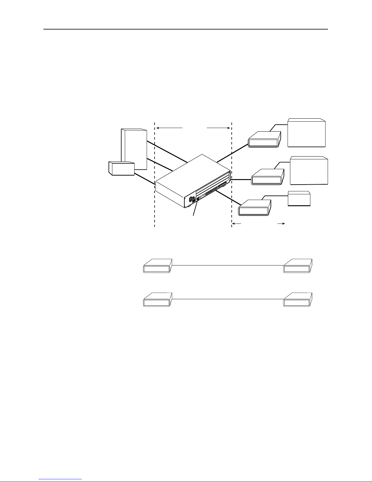
Figure 1-1 shows a network application using a 2-port Hotwire 8786 M/HDSL
Termination Unit for access concentration in a central office (CO). A frame relay
switch and a router are connected, through the termination unit, to partner units
supporting a host or router, and frame relay encapsulated or unframed data.
About the Model 7986 Standalone Termination Unit
Frame
Relay
Switch
Router
7986 (G.703)
CO Site
LTU
CO Site
8786 or 8784
Termination Unit
in 8600 DSLAM
2.048 Mb
over
SDSL
EIA-530A
V.35
7985
Customer
Premises (CP)
G.703
7986
G.703
7986
E1 Host
(Frame Relay
Encapsulated
Data)
Router
(Frame Relay
Encapsulated
Data)
Router
Customer
Premises
NTU
7985
V.35
7986 (G.703)
Figure 1-1. Sample M/HDSL Configurations
NOTE:
A cross over cable (pins 1, 2 to 4, 5) is required for connecting two 7986
termination units back-to-back.
7986-A2-GB20-00
September 1998
7986
G.703
98-16151
1-3
Page 14
About the Model 7986 Standalone Termination Unit
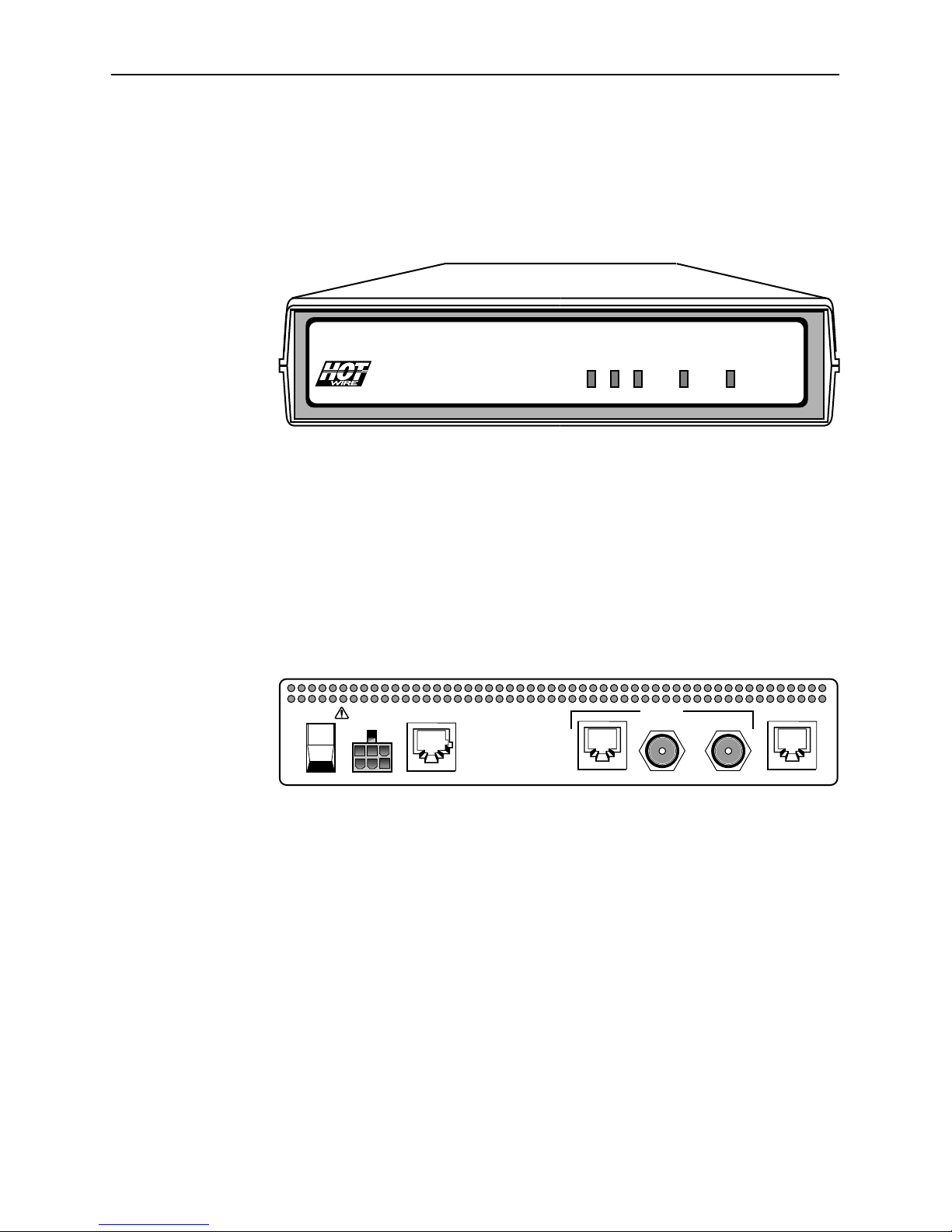
Front Panel LED Status Indicators
Figure 1-2 shows the front panel of the Model 7986 Standalone Termination Unit.
For more information on front panel LEDs, refer to Chapter 4,
TM
TM
7986 M/HDSL
Figure 1-2. Hotwire Model 7986 Standalone Termination Unit Front Panel
POWER
ALARM
TEST
Monitoring the Unit
DSL
G.703
.
98-16087
Rear Panel Interface Connections
Figure 1-3 shows the physical interfaces of the Model 7986 Standalone
Termination Unit.
POWER DSLCOM
I
O
Figure 1-3. Hotwire Model 7986 Standalone Termination Unit Rear Panel
G.703
TX RX
75Ω120Ω
98-16005
1-4
September 1998
7986-A2-GB20-00
Page 15
MIB Support
About the Model 7986 Standalone Termination Unit
The Model 7986 Standalone Termination Unit supports traps as defined in
RFC 1215. They may include variable-bindings specified in the following MIBs:
H MIB II (RFC 1573) – Defines the general objects for use with a network
management protocol in TCP/IP internets and provides general information
about the Model 7986 Standalone Termination Unit.
H Enterprise MIB – Supports configuration, status, statistics, and tests.
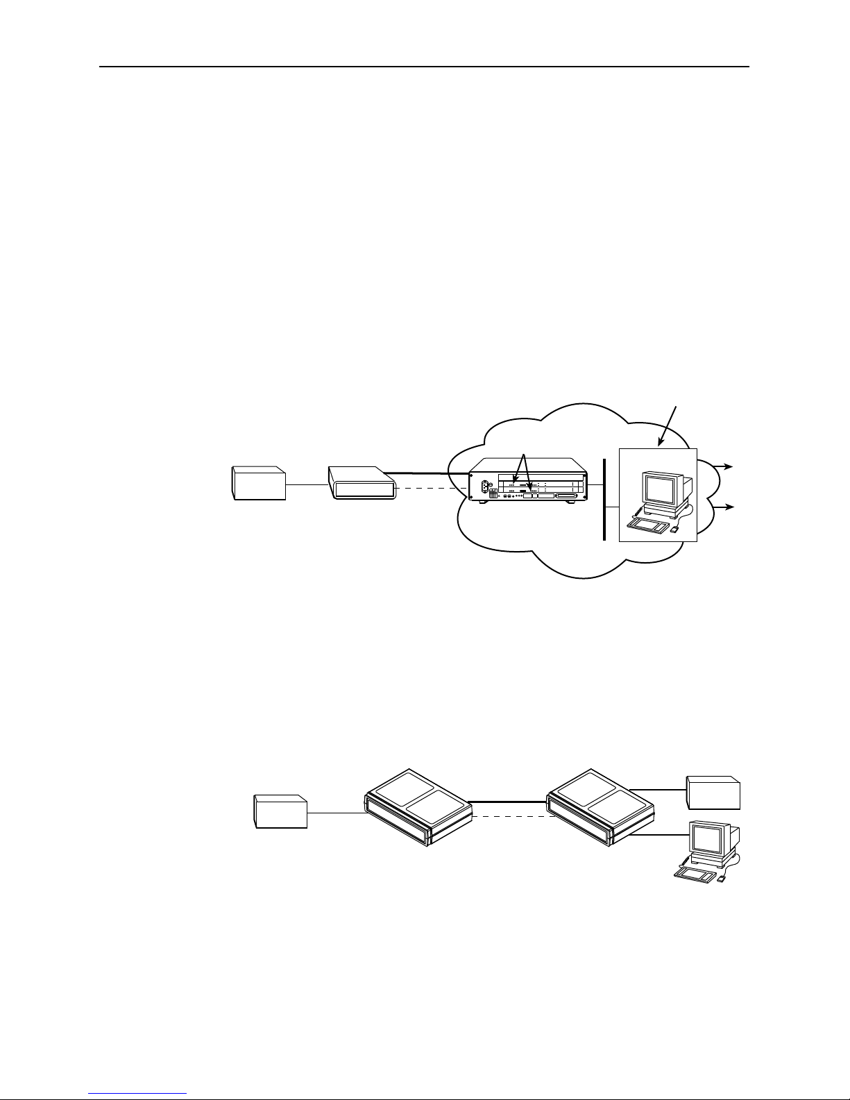
Figure 1-4 illustrates a typical M/HDSL SNMP configuration. Refer to Chapter 8,
IP Addressing
Router
G.703
and Appendix B,
4-Wire
DSL
7986
EOC
Standards Compliance for SNMP Traps
Operation, Maintenance
and Provisioning Center
Network
AC
T5A
250V
RTN48V
AAB B
AC
INPUT
48VDC CLASS 2 OR
LIMITED PWR SOURCE
8600
DSLAM
8786
OK
Alrm
TestTXRX
SYSTEM
OK
Alrm
Test1234
SYSTEM
OK
Alrm
Test1234
SYSTEM
DC FUSES
T4A, MIN. 48V
5
46
3
2
1
.
STACK
A
B
POSITION
Col1234
ETHERNET
123
4
G.703 ALRM
123
4
G.703 ALRM
DC PWR
FAN
.
.
ALM
A
B
.
IN
DSL PORT
DSL PORT
LINK-UP
DSL PORT
LINK-UP
MCC 1
2
OUT SERIAL
Ethernet
Interface
8546
RADSL
8715
SDSL
8715
SDSL
3
3
2
1
SNMP NMS
.
Data
Voice
Ethernet
LAN
98-16088
Figure 1-4. M/HDSL SNMP Configuration
Figure 1-5 illustrates an M/HDSL SNMP configuration connected directly to the
Communications Port. Refer to Chapter 8,
Standards Compliance for SNMP Traps
Router
G.703
7986
.
DSL
EOC
IP Addressing
and Appendix B,
G.703
Router
COM
7986
SNMP NMS
98-16090
Figure 1-5. M/HDSL Local SNMP Configuration
7986-A2-GB20-00
September 1998
1-5
Page 16

About the Model 7986 Standalone Termination Unit
This page intentionally left blank.
1-6
September 1998
7986-A2-GB20-00
Page 17

Using the Asynchronous Terminal
Interface
User Interface Access
You can communicate with the Hotwire Model 7986 Standalone Termination Unit
with an asynchronous terminal interface (ATI) using one of the following methods:
H Direct connection through the COM port.
H Telnet session through the Embedded Operations Channel (EOC).
2
NOTE:
Only one terminal interface session can be active at a time, and another
user’s session cannot be forced to end. To automatically log out a user due to
inactivity, enable the Inactivity Timeout option (see Table A-5, Telnet Sessions
Options, in Appendix A,
Security can limit ATI access several ways. To limit user access or set up login
IDs, refer to Chapter 7,
Communication Port Settings
Ensure that the device you connect communicates using these settings:
H Data rate set to 9.6 kbps.
H Character length set to 8.
H Parity set to None.
H Stop Bits set to 1.
Configuration Option Tables
Security
.
).
7986-A2-GB20-00
September 1998
2-1
Page 18

Using the Asynchronous Terminal Interface
Initiating an ATI Session
The Main Menu screen is displayed on the screen unless a login ID and
password is required or the ATI is already in use.
If security is enabled on the Model 7986 Standalone Termination Unit and you
used Telnet to access it directly (you did not log in through the MCC), the system
prompts you for a login ID and password.
Login Hotwire
LOGIN
Login ID:
Enter Password:
––––––––––––––––––––––––––––––––––––––––––––––––––––––––––––––––––––––––––––––––
Ctrl-a to access these functions E
Model: 7986
xit
After you enter a valid login ID and password, the Main Menu appears. If you
enter an invalid login ID and password after three attempts, the Telnet session
closes or the terminal connection returns to an idle state. Refer to Chapter 7,
Security
.
If the ATI is already in use, you will see a connection refused or
connection failed message (if you are using a Telnet session), or you will
see the IP address of the other user (if you are using the Management Serial
port).
2-2
September 1998
7986-A2-GB20-00
Page 19
Using the Asynchronous Terminal Interface
Screen
Area
Screen
Function
Keys
Area
main Access Level: Administrator Hotwire
MAIN MENU
Status
Test
Configuration
Control
––––––––––––––––––––––––––––––––––––––––––––––––––––––––––––––––––––––––––––––––
Ctrl-a to access these functions E
Model 7986
xit
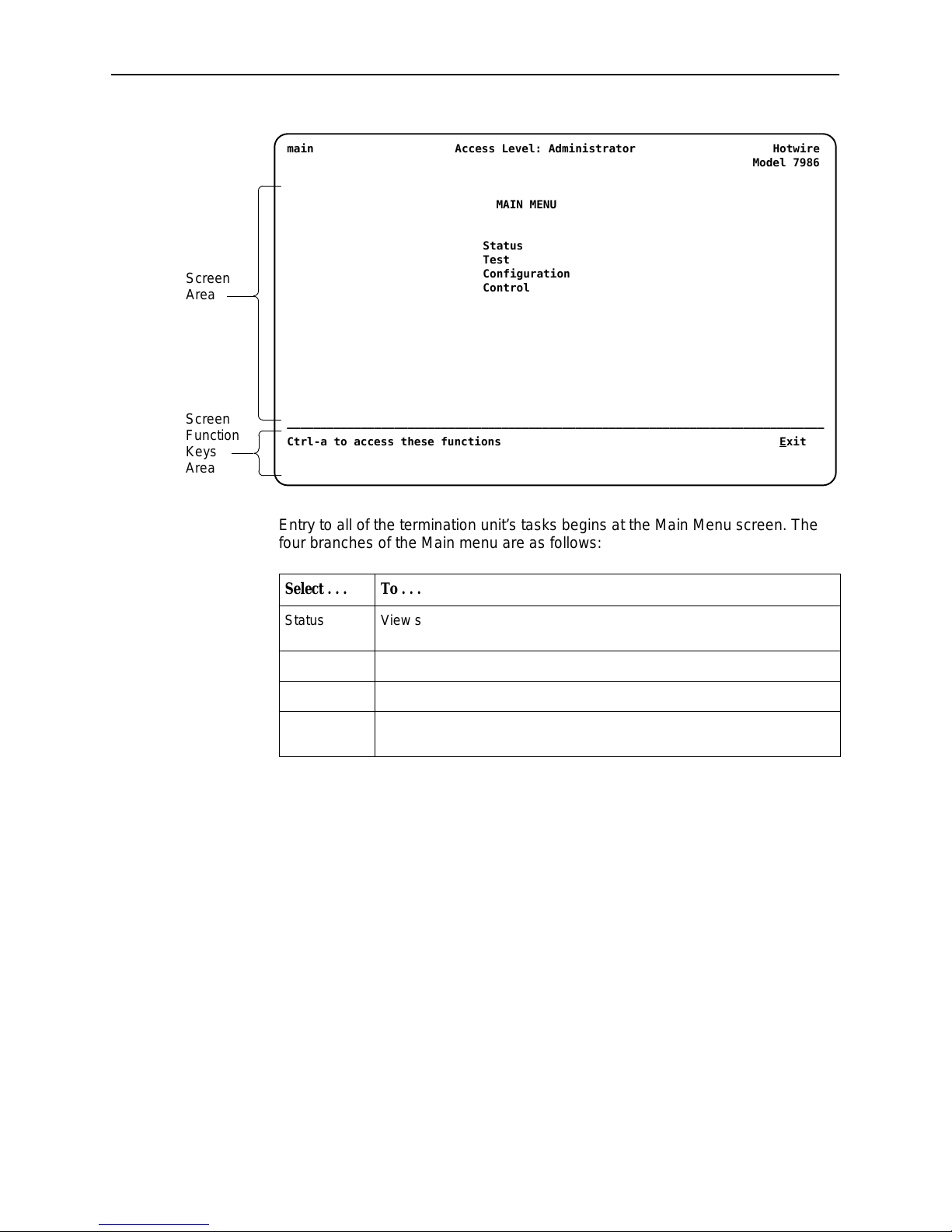
Entry to all of the termination unit’s tasks begins at the Main Menu screen. The
four branches of the Main menu are as follows:
Select . . .
To . . .
Status View system status, diagnostic test results, statistics, LEDs, and device
identity information.
Test Select and cancel tests for the termination unit’s interfaces.
Configuration Display and edit the configuration options.
Control Change the device identity, administer logins, download new firmware, or
initiate a power-up reset of the termination unit.
After selecting an option, what appears on the screens depends on the:
H Current configuration – How your termination unit is currently configured.
H Effective security access level – An access level that is typically set by the
system administrator for each interface and each user.
H Data selection criteria – What you entered in previous screens.
7986-A2-GB20-00
September 1998
2-3
Page 20
Using the Asynchronous Terminal Interface
S
t
e
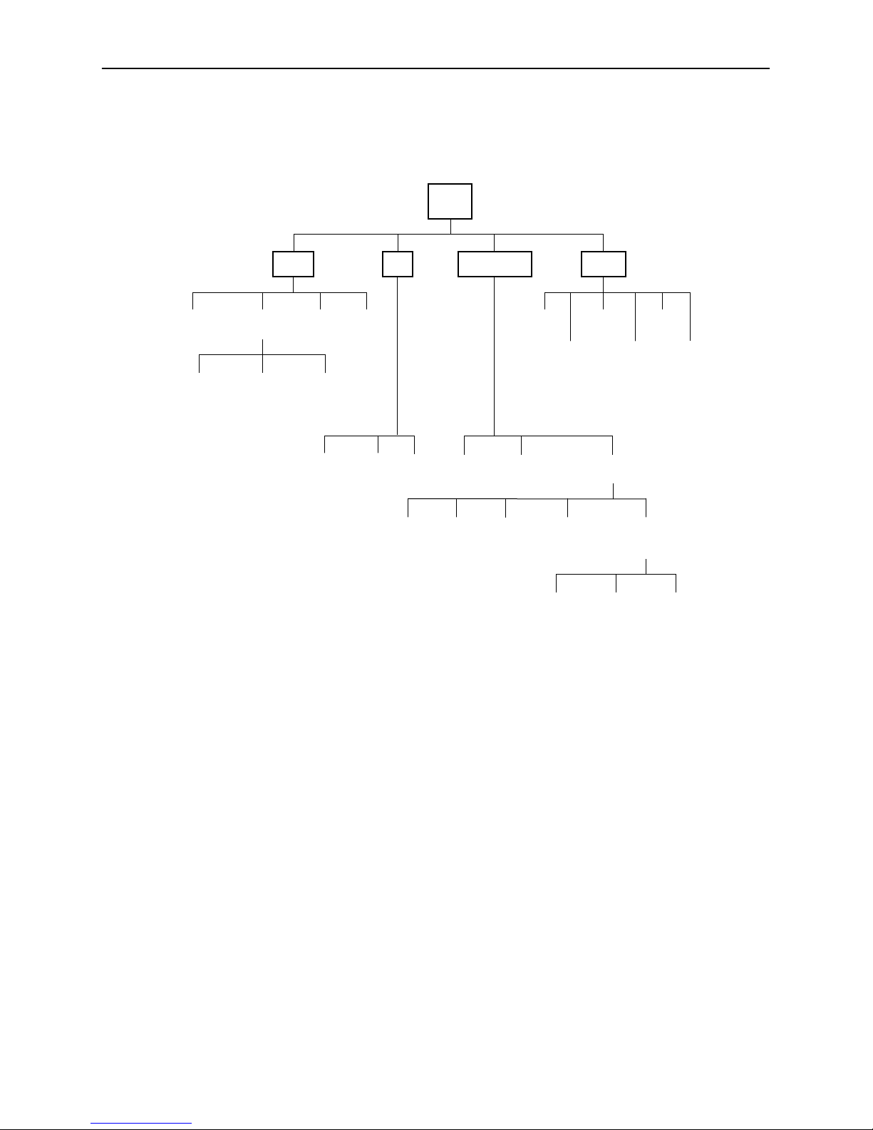
The following illustration shows the menu paths to the different ATI screens.
Main
ystem and
Test Status
Network
Error
Statistics
Status Test
Performance
Statistics
Network
Performance
Statistics
Display
LEDs
G.703
Statistics
Network
and
G.703 T est
Identity
Device
T ests
Abort
T ests
Network G.703
All
Factory
Config
Configuration Control
Change
Identity
Configuration
Loader
System
Options
Communication
Session
Download
Code
Administer
Logins
Current Configuration
Edit/Display
Port
Communication
Telnet
Protocol Option
Communication
Reset
AutoRate
Apply
Download
Management
and
Rese
Devic
SNMP
Traps
98-16071
2-4
September 1998
7986-A2-GB20-00
Page 21
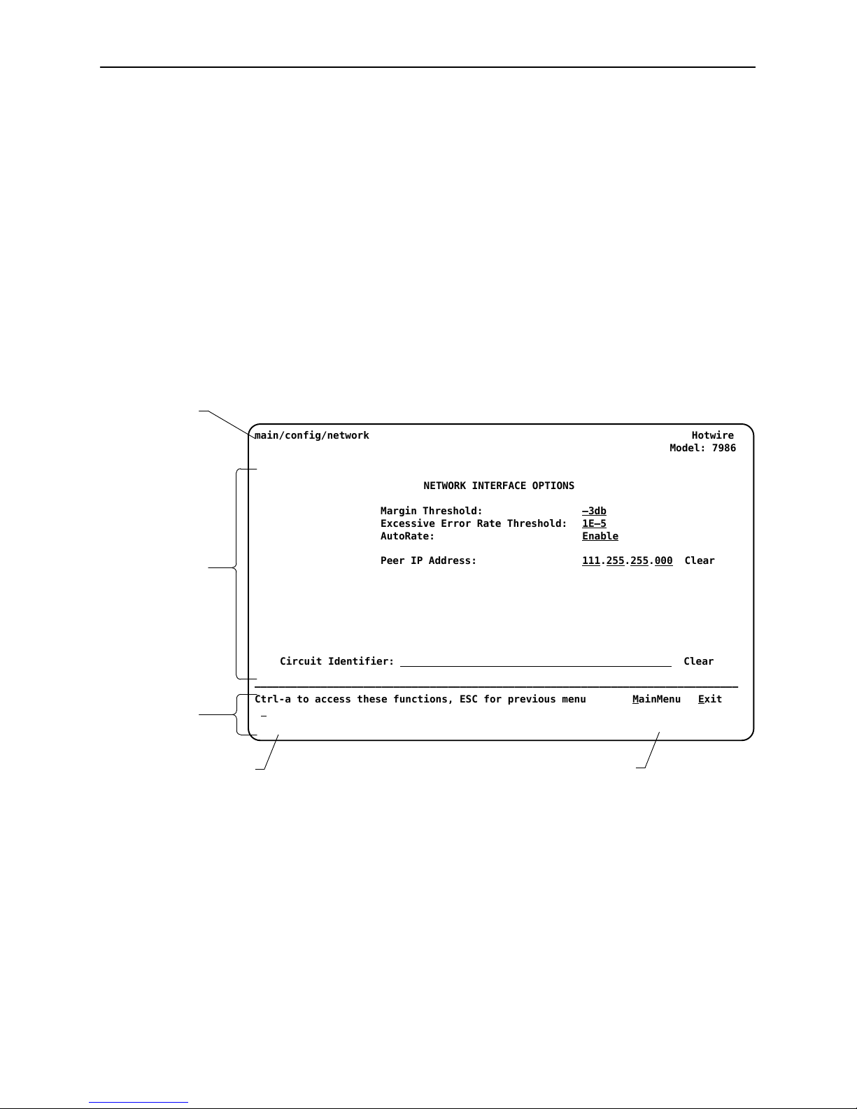
Screen Work Areas
There are two user work areas:
H Screen area – This is the area above the dotted line that provides the menu
H Screen function key area – This is the area below the dotted line that lists
Menu Path
Using the Asynchronous Terminal Interface
path, menus, and input fields.
The menu path appears as the first line on the screen. In this manual, the
menu path is presented as a menu selection sequence with the names of the
screens:
Main Menu→Configuration →Load Configuration From→Network
Interface Options
function keys specific to the screen, field value choices, and system
messages.
Input
Fields
Screen
Function
Keys
Field V alue
Choices
main/config/network Hotwire
NETWORK INTERFACE OPTIONS
Margin Threshold: –3db
Excessive Error Rate Threshold: 1E–5
AutoRate: Enable
Peer IP Address: 111.255.255.000 Clear
Circuit Identifier:
––––––––––––––––––––––––––––––––––––––––––––––––––––––––––––––––––––––––––––––––
Ctrl-a to access these functions, ESC for previous menu M
S
ave
Select: 1E–4, 1E–5, 1E–6, 1E–7, 1E–8, 1E–9 LOS at Net, Pt
Model: 7986
Clear
ainMenu Exit
n
System
Messages
7986-A2-GB20-00
September 1998
2-5
Page 22

Using the Asynchronous Terminal Interface
Navigating the Screens
You can navigate the screens by:
H Using keyboard keys
H Using screen function keys
H Switching between the two screen work areas
Keyboard Keys
Use the following keyboard keys to navigate within the screen.
Press . . .
Ctrl-a Move cursor between the screen area and the screen function
Esc Return to the previous screen.
Tab Move cursor to the next field on the screen.
Backspace Move cursor to the previous field on the screen.
Return (Enter) Accept entry or display valid options on the last row of the screen
Ctrl-k Tab backwards (move cursor one field to the left).
Spacebar Select the next valid value for the field.
Delete (Del) Delete character that the cursor is on.
Up Arrow or Ctrl-u Move cursor up one field within a column on the same screen.
Down Arrow or Ctrl-d Move cursor down one field within a column on the same screen.
Right Arrow or Ctrl-f Move cursor one character to the right if in edit mode.
Left Arrow or Ctrl-b Move cursor one character to the left if in edit mode.
Ctrl-l Redraw the screen display, clearing information typed in but not
To . . .
keys area below the dotted line at the bottom of the screen.
when pressed before entering data or after entering invalid data.
yet entered.
" Pr ocedure
To make a menu or field selection:
1. Press the Tab key or the right arrow key to position the cursor on a menu or
field selection. Each selection is highlighted as you press the key to move the
cursor from position to position.
2. Press Enter.
The selected menu or screen appears.
3. Continue Steps 1 and 2 until you reach the screen you want.
2-6
September 1998
7986-A2-GB20-00
Page 23

Screen Function Keys
Using the Asynchronous Terminal Interface
The current setting or value appears to the right of the field name. You can enter
information into a selected field by:
H Typing in the first letter(s) of a field value or command.
H Switching from the screen area to the screen function area below the dotted
line and selecting or entering the designated screen function key.
If a field is blank and the Field Values screen area displays valid selections, press
the spacebar and the first valid value for the field will appear. Continue pressing
the spacebar to scroll through other valid values.
All screen function keys located below the dotted line operate the same way
(upper- or lowercase) throughout the screens.
For the screen
function . . .
Select . . . And press Enter to . . .
ClrFar F or f Clear far-end network statistics and refresh the screen.
ClrNear N or n Clear near-end network statistics and refresh the screen.
Delete L or l Delete data.
Exit E or e Terminate the async terminal session.
MainMenu M or m Return to the Main Menu screen.
New N or n Enter new data.
PgDn D or d Display the next page, or group of entries.
PgUp U or u Display the previous page, or group of entries.
ResetMon R or r Reset an active Monitor 511 test counter to zero.
Save S or s Save information.
7986-A2-GB20-00
September 1998
2-7
Page 24

Using the Asynchronous Terminal Interface
Switching Between Screen Work Areas
Select Ctrl-a to switch between the two screen work areas to perform all screen
functions.
" Procedure
To access the screen function area below the dotted line:
1. Press Ctrl-a to switch from the screen area to the screen function key area
below the dotted line.
2. Select either the function’s designated (underlined) character or press the
Tab key until you reach the desired function key.
Example:
To save the current screen, type s or S (Save).
3. Press Enter.
4. To return to the screen area above the dotted line, press Ctrl-a again.
main/config/network Hotwire
NETWORK INTERFACE OPTIONS
Margin Threshold: –3db
Excessive Error Rate Threshold: 1E–5
AutoRate Disable
DSL Line Rate 528
Peer IP Address: 111.255.255.000 Clear
Circuit Identifier:
––––––––––––––––––––––––––––––––––––––––––––––––––––––––––––––––––––––––––––––––
Ctrl-a to access these functions, ESC for previous menu M
S
ave
Model: 7986
Clear
ainMenu Exit
2-8
September 1998
7986-A2-GB20-00
Page 25

Ending an ATI Session
Use the Exit function key from any screen to terminate the session.
" Procedure
To end a session with the asynchronous terminal interface:
1. Press Ctrl-a to go to the screen function key area below the dotted line.
2. Save changes if required. A confirmation message appears if you have made
but not saved changes to your configuration.
Using the Asynchronous Terminal Interface
3. Tab to E
xit (or type e or E) and press Enter.
7986-A2-GB20-00
September 1998
2-9
Page 26

Using the Asynchronous Terminal Interface
This page intentionally left blank.
2-10
September 1998
7986-A2-GB20-00
Page 27

Initial Startup and Configuration
Overview
This chapter provides instructions on how to access and configure your unit for
the first time. This chapter includes procedures for:
H Connecting power to the unit.
H Connecting the unit to the network.
H Connecting a system terminal.
H Providing initial unit identity information or changing existing identity
information.
H Configuring your unit using internal switchpacks or using the Configuration
Edit menus.
H Choosing the current or factory default configuration options or downloading
configuration options from a TFTP server.
H Modifying current configuration options using the Configuration Edit/Display
menu.
H Saving your changes.
H Downloading unit firmware from a TFTP server.
3
7986-A2-GB20-00
September 1998
3-1
Page 28

Initial Startup and Configuration
1
Connecting Power to the Unit
If your package includes a power pack:
Plug the power pack into an ac outlet
having a nominal voltage rating between 100–240 Vac. Connect the output cable
of the power pack to the connector marked POWER on the rear panel.
If your package includes a direct-connection dc power cable:
an external dc power source as described in
External DC Power Source
.
Connecting the Unit to an Optional
Optional Power Sources
Using the optional dc power cable, the unit is capable of operating on a +24 Vdc
power source. To select the power, choose one of the following power supply
types.
Connecting the Unit to an Optional External DC Power Source
Using the dc power cable, the Hotwire Model 7986 Standalone Termination Unit
is capable of operating on a +24 Vdc power supply.
NOTE:
The E1 M/HDSL Unit is typically powered by the ac power module. Use the
following procedures only if you want to use an optional dc power source.
" Procedure
Connect the unit to
To use the dc power cable:
1. Connect the green wire to a suitable earth ground.
2. Connect the orange wire to the +24 Vdc source.
3. Connect the white wire to the return.
4. Cut the black, red, and blue wires off at the outer insulation.
5. Plug the power connector into the Model 7986 Standalone Termination Unit.
1
2
3
4
5
6
Black
Red
Green
White
Orange
Blue
X
X
Earth Ground
RTN
+24 Vdc
X
98-14158-0
+24 Vdc Power Supply Pinouts
3-2
September 1998
7986-A2-GB20-00
Page 29

Connecting to the Network
" Procedure
To connect your unit to the network:
1. Connect one end of the network cable into the rear panel DSL jack. Connect
the other end to your DSL network interface.
NOTES:
A cross over cable (pins 1, 2 to 4, 5) is required for connecting two 7986
termination units back-to-back.
Do
not
use a flat VF network cable as this may severely degrade the
performance of the termination unit. Use only Cat 5 twisted-pair network
cable.
Connecting to a System Terminal
Initial Startup and Configuration
An optional system maintenance terminal may be attached to your Hotwire Model
7986 Standalone Termination Unit through the modular jack on the rear panel.
The system maintenance terminal allows you to view the status of the unit, and
change configuration options. The terminal must be a VT100-compatible terminal
or a PC running terminal emulation software.
Connect the 9-pin end of the terminal cable into a COM port on your PC. Plug the
other end into the modular jack on the rear panel. If your PC requires a 25-pin
connector to the COM port, see Appendix C,
correct cable pinouts.
Make sure the communication parameters on your PC or terminal are set to:
H 9600 baud
H 8 bit characters
H no parity
H 1 stop bit
H no flow control
Press Enter from your terminal or PC to activate the Main Menu for the attached
unit. The system runs diagnostics and status checks. After a few moments, the
Main Menu or Logon screen appears on your terminal.
Cables and Pin Assignments
, for the
7986-A2-GB20-00
September 1998
3-3
Page 30

Initial Startup and Configuration
Entering Identity Information
After accessing your unit for the first time, use the Change Identity screen to
determine SNMP administrative system information that will be displayed on the
Identity screen of the Status branch. To access the Identity screen, follow this
menu selection sequence:
Main Menu→Control→Change Identity
main/control/change_identity Hotwire
IDENTITY
System Name: lllQJ98-001
System Location: Bldg. A412, 2nd Floor, Left cabinet
System Contact: C. Parker 800-727-2396 pager 888-555-1212 Clear
––––––––––––––––––––––––––––––––––––––––––––––––––––––––––––––––––––––––––––––––
Ctrl-a to access these functions, ESC for previous menu M
S
ave
Model: 7986
Clear
Clear
ainMenu Exit
Fields on the Card Identity screen are null until you enter values. The field values
display 40 characters with a maximum field length of 128 characters. If a field
value is greater than 40 characters in length, use the left or right arrow keys to
view the remaining text. Valid values are any printable ASCII character. ASCII
printable characters include:
H Numeric 0–9
H Upper or lower case A–Z
H Space
H All ASCII symbols except the caret (^)
Select Clear to reset a field to a null value.
" Procedure
To enter Change Identity screen information:
1. Position the cursor in the System Name field. Enter a name unique in your
network to identify the SNMP managed node (or unit).
The maximum length of System Name is 128 characters.
2. Position the cursor in the System Location field. Enter the physical location of
the unit.
The maximum length of System Location is 128 characters.
3-4
September 1998
7986-A2-GB20-00
Page 31

Initial Startup and Configuration
3. Position the cursor in the System Contact field. Enter the name and contact
information for the person responsible for the unit.
The maximum length of System Contact is 128 characters.
4. Press Ctrl-a to switch to the screen function key area below the dotted line.
5. Select S
ave and press Enter.
Choosing a Configuration Mode
You can make configuration changes either through a VT100 and the unit’s
Configuration menus or by manually changing switches on the board. The unit
comes defaulted to allow settings to be made through the Configuration menus.
Configuring the Unit Using the Configuration Menus
Use the Configuration menu to select, display, or change configuration option
settings.
Configuration Options
NOTE:
The 7986 Standalone Termination Unit is pre-configured as an NTU. If you
are using this unit as an NTU, the following configuration options may not
need to be performed.
The Model 7986 Standalone Termination Unit is shipped with factory settings in
the Default Factory configuration area. You can find default information by:
7986-A2-GB20-00
H Referring to
H Accessing the Configuration branch of the Model 7986 Standalone
Termination Unit menu.
The Model 7986 Standalone Termination Unit has two sets of configuration option
settings. The Current Configuration matches the Default Factory Configuration
until modified and saved by the user.
Configuration Option Area
Current Configuration The Model 7986 Standalone Termination Unit’s active
Default Factory Configuration A read-only configuration area containing the factory
If the factory default settings do not support your network’s configuration, you can
customize the configuration options for your application.
Appendix A,
September 1998
Configuration Option Tables
Configuration Option Set
set of configuration options.
default configuration options.
.
3-5
Page 32

Initial Startup and Configuration
Configuring the Unit Using the Internal Switches
Use internal Switchpacks S1 and S2 to manually configure the unit. Use
Figure 3-1 to locate Switchpacks S1 and S2.
!
HANDLING PRECAUTIONS FOR
STATIC-SENSITIVE DEVICES
This product is designed to protect sensitive components from damage
due to electrostatic discharge (ESD) during normal operation. When
performing installation procedures, however, take proper static control
precautions to prevent damage to equipment. If you are not sure of the
496-15104
" Procedure
proper static control precautions, contact your nearest sales or service
representative.
To configure the unit using internal Switchpacks S1 and S2:
1. Power down the unit and remove the enclosure cover, exposing the circuit
board.
2. Locate Switchpack S1 using Figure 3-1.
3. Set Switch 1 on Switchpack S1 to ON to enable Switchpacks 1 and 2.
4. After you enable the switchpacks, you must set the switches to your desired
configuration. Refer to Figure 3-1 and Table 3-1.
5. Replace and secure the cover.
6. Power up the board to reset and enable the new configuration.
3-6
September 1998
7986-A2-GB20-00
Page 33

Switchpack Locations
Use Figure 3-1 to locate Switchpacks S1 and S2.
Switchpack S1 & S2
ON
12345
678
ON
12345
678
S2
S1
Initial Startup and Configuration
Front
Rear
Figure 3-1. Hotwire Model 7986 Standalone Termination Unit Switchpack
Locations
98-16073
7986-A2-GB20-00
September 1998
3-7
Page 34

Initial Startup and Configuration
Switchpack Definitions
Manually change configuration options by moving Switchpack S1 DIP switches
on the card. Table 3-1 lists Switchpack S1 definitions.
Table 3-1. Switchpack S1 Definitions
Switch # . . .
1 Enables or disables Switchpacks S1 and S2.
2 Controls line termination.
3 Selects the unit’s primary timing source. Only valid for units configured
4 Controls the unit’s E1 line coding.
5 Not used
6 Enables CRC-4 monitoring.
7 Controls whether Channel 16 contains signaling information or data.
Allows you to . . .
OFF = Switchpacks Disabled
ON = Switchpacks Enabled
OFF = 120 Ohm
ON = 75 Ohm
as LTU.
OFF = Internal Clock
ON = External Clock
OFF = HDB3
ON = AMI
OFF = Enable CRC-4
ON = Disable CRC-4 monitoring
OFF = Channel 16 is used for signaling
ON = Channel 16 is used for data
Default in Bold
3-8
8 Not used
September 1998
7986-A2-GB20-00
Page 35

Table 3-2 lists Switchpack S2 definitions.
Table 3-2. Switchpack S2 Definitions
Initial Startup and Configuration
Switch # . . .
1 Control whether the unit is an LTU or an NTU.
2 Control enabling and disabling of the Autorate capability. Only valid for
3, 4, 5 Select one of eight preset DSL line rates (refer to Table 3-3).
6, 7 Not used
8 Emergency Use Only – The Model 7986 has two banks of flash
Allows you to . . .
OFF = NTU
ON =LTU
units configured as L TU.
OFF = Autorate Disabled
ON = Autorate Enabled
All OFF = 2064
memory used to hold executable firmware This switch allows you to
switch between the two versions of firmware. This switch is
independent from the position of Switch 1 on Switchpack S1
(switchpack enable/disable).
OFF = Current Firmware
ON = Previous FW
Default in Bold
Use Table 3-3 to set the DSL Line Rate. Defaults are shown in bold.
Table 3-3. DSL Line Rate, Switches 3 – 5 on Switchpack S2
Switch Position
5 4 3
OFF ON ON 400 kbps
ON OFF OFF 528 kbps
ON OFF ON 784 kbps
ON ON OFF 1040 kbps
ON ON ON 1552 kbps
OFF OFF OFF 2064 kbps
DSL Line Rate
7986-A2-GB20-00
September 1998
3-9
Page 36

Initial Startup and Configuration
Accessing and Displaying Configuration Options
To display configuration options, you must first load a configuration into the edit
area.
To load a configuration option set into the configuration edit area, follow this
menu selection sequence:
Main Menu→Configuration (Load Configuration From)
main/configuration Hotwire
LOAD CONFIGURATION FROM:
Current Configuration
Configuration Loader
Default Factory Configuration
––––––––––––––––––––––––––––––––––––––––––––––––––––––––––––––––––––––––––––––––
Ctrl-a to access these functions, ESC for previous menu M
Model: 7986
ainMenu Exit
Make a selection by placing the cursor at your choice and pressing Enter.
If you select . . .
Current
Configuration
Default Factory
Configuration
Then . . .
The selected configuration option set is loaded and the
Configuration Edit/Display menu screen appears.
The selected configuration option set is loaded and the
Configuration Edit/Display menu screen appears.
Configuration
Loader
3-10
The Configuration Loader screen is displayed allowing you to
upload or download configurations from a TFTP server.
September 1998
7986-A2-GB20-00
Page 37

Configuration Edit/Display
The Configuration Edit/Display screen is displayed when the current, customer, or
default configuration is loaded. To access the Configuration Edit/Display screen,
follow this menu selection sequence:
Main Menu→Configuration →Current Configuration
–
or –
Main Menu→Configuration →Default Factory Configuration
Initial Startup and Configuration
main/config/edit Hotwire
CONFIGURATION EDIT/DISPLAY
Network
G.703
System Options
Communication Port
Management and Communication
–––––––––––––––––––––––––––––––––––––––––––––––––––––––––––––––––––––––––––––––
Ctrl-a to access these functions, ESC for previous menu M
S
ave
See Appendix A,
Configuration Option Tables
, for a list and explanation of the
Model: 7986
ainMenu Exit
configuration options available.
Select . . .
Network Network Interface Options, Table A-1 DSL network interfaces on
G.703 G.703 Interface Options,
To Access the . . . To Configure the . . .
the unit.
G.703 interface.
Table A-2
System
Options
Communication
Port
Management
and
Communication
7986-A2-GB20-00
System Options, Table A-3 General system options of
the unit.
Communication Port Options, Table A-4 Unit’s COM port options.
H Telnet Sessions Options,
Table A-5
H Communication Protocol Options,
Management support of the
unit through SNMP and
Telnet.
Table A-6
H SNMP Traps Options, Table A-7
September 1998
3-11
Page 38

Initial Startup and Configuration
Configuring AutoRate
The M/HDSL AutoRate function is controlled from the Network Interface Options
screen and allows you to enable or disable AutoRate only from a unit configured
as an LTU. To access the Network Interface screen, follow this menu selection
sequence:
Main Menu→Configuration →Network
main/config/network Hotwire
NETWORK INTERFACE OPTIONS
Margin Threshold: –3db
Excessive Error Rate Threshold: 1E–6
AutoRate Disable
DSL Line Rate 528
Peer IP Address: 111.255.255.000 Clear
Circuit Identifier:
––––––––––––––––––––––––––––––––––––––––––––––––––––––––––––––––––––––––––––––––
Ctrl-a to access these functions, ESC for previous menu M
S
ave
ainMenu Exit
" Procedure
The AutoRate option is defaulted to Disable. To enable AutoRate:
1. Position the cursor in the AutoRate field and press the spacebar.
The AutoRate field toggles to Enable and the DSL Line Rate field displays.
Model: 7986
Clear
2. Enter a DSL Line Rate and press Enter.
Your payload rate is set to a default value of 1984. Use Table 3-5, Fixed Rate
Payload Rates and DSL Line Rates, to set your DSL Line Rate and Payload
Rate according to whether you are configured for Voice (signaling) or Data.
3-12
September 1998
7986-A2-GB20-00
Page 39

Initial Startup and Configuration
Table 3-4 provides the maximum payload rates achievable for each DSL line rate
and the number of time slots required to achieve that payload rate depending on
whether you are using signaling (time slots 0 and 16) or data only (time slot 0).
Table 3-4. Fixed Rate Payload Rates and DSL Line Rates
Voice Mode
(G.703 to G.703 )
Maximum
DSL Line
Rate (kbps)
2064 1920 30 1984 31 1984 31
1552 1408 22 1472 23 1536 24
1040 896 14 960 15 1024 16
784 640 10 704 11 768 12
528 384 6 448 7 512 8
400 256 4 320 5 384 6
Payload Rate
(kbps)
Time
slots
Data Mode
(G.703 to G.703 )
Maximum
Payload Rate
(kbps)
Time
slots
Data Mode
(G.703 to EIA-530)
Maximum
Payload Rate
(kbps)
Time
slots
7986-A2-GB20-00
September 1998
3-13
Page 40

Initial Startup and Configuration
Configuration Loader
The Configuration Loader screen allows you to upload configurations to and
download configurations from a TFTP server. To access the Configuration Loader
screen, follow this menu selection sequence:
Main Menu→Configuration →Configuration Loader
main/config/config_loader Hotwire
CONFIGURATION LOADER
Image File Name:
TFTP Server IP Address: 000
TFTP Transfer Direction: Download from Server
Destination: DSL
Start Transfer: Yes
Packets Sent: 0000000
Packets Received: 0000000
Bytes Sent: 0000000
Bytes Received: 0000000
Transfer Status: Transfer Pending
Activate new configuration? No
–––––––––––––––––––––––––––––––––––––––––––––––––––––––––––––––––––––––––––––––
Ctrl-a to access these functions, ESC for previous menu M
.000.000.000 Clear
ainMenu Exit
" Pr ocedure
To upload or download a configuration:
Model: 7986
Clear
3-14
1. Position the cursor in the Image File Name field. Type the name of the file to
be downloaded, or the name to be used for the file to be uploaded.
The file name may be a regular path name expression of directory names
separated by a forward slash (/) ending with the file name. The total path
name length can be up to 128 characters.
DOS machine:
If the TFTP server is hosted by a DOS machine, then
directory and file names must consist of eight or less characters with an
optional suffix of up to three characters. The system will automatically upload
the configuration file and create directories and file names as needed.
UNIX machine:
If your server is hosted by a UNIX machine, the configuration
file you name must already exist. It will not be created on the UNIX system by
the TFTP server. It is critical that you work with your system administrator to
plan the naming conventions for directories, filenames, and permissions so
that anyone using the system has read and write permissions.
September 1998
7986-A2-GB20-00
Page 41

Initial Startup and Configuration
2. Position the cursor in the TFTP Server IP Address field. Enter the TFTP
server IP address.
3. Position the cursor in the Destination field. Use the spacebar to select a
network destination for the TFTP server. Select DSL if the TFTP server
destination is the DSL link or COM if the TFTP destination is the COM port.
4. Position the cursor in the TFTP Transfer Direction field. Use the spacebar to
select Download from Server or Upload to Server.
5. Position the cursor at the Start Transfer field. Use the spacebar to select Yes.
Press Enter.
When the data transfer is complete, the Transfer Status field changes to
Completed successfully.
6. Position the cursor at the Activate New Configuration field and select Yes to
activate a new downloaded configuration. Press Enter.
NOTE:
The configuration options DSL Mode and Telnet Session are not changed
when a new configuration is loaded. You must change these settings with the
appropriate configuration menus after the new configuration is activated. See
Table A-3, System Options, and Table A-5, Telnet Sessions Options, in
Appendix A,
Configuration Option Tables
.
7986-A2-GB20-00
September 1998
3-15
Page 42

Initial Startup and Configuration
Saving Configuration Options
When changes are made to the configuration options through the Configuration
Edit/Display branch, the changes must be saved to take effect. Use the S
or Save Configuration screen.
" Procedure
To save configuration options changes:
1. Press Ctrl-a to switch to the screen function key area below the dotted line.
ave key
2. Select S
ave and press Enter.
NOTE:
When Exit is selected before Save, or Save has been selected from any
menu in the Configuration/Edit branch, a Save Configuration screen appears
requiring a Yes or No response.
main/config/saveprompt Hotwire
SAVE CONFIGURATION
Save Changes? No
WARNING:
An answer of “yes” will cause the system
to reset as if it had been powered off and on!
–––––––––––––––––––––––––––––––––––––––––––––––––––––––––––––––––––––––––––––––
Ctrl-a to access these functions, ESC for previous menu M
Command Complete
If the Telnet Session configuration option is changed, a message displays on the
Save Configuration screen warning that an answer of Yes will cause the Telnet
session to disconnect. Do not answer Yes unless you are prepared to disconnect.
Model: 7986
ainMenu Exit
If the DSL Mode configuration option is changed, a message displays on the
Save Configuration screen warning that an answer of Yes will cause the system
to reset. Do not answer Yes unless you are prepared to reset.
If you select . . .
Yes The configuration is saved.
No The Main Menu appears and changes are not saved.
3-16
Then . . .
September 1998
7986-A2-GB20-00
Page 43

Download Code
Initial Startup and Configuration
The Download Code screen allows you to download firmware from a TFTP
server. To access the Download Code screen, follow this menu selection
sequence:
Main Menu→Control →Download Code
main/control/download_code Hotwire
DOWNLOAD CODE
Image File Name:
TFTP Server IP Address: 000
Destination: DSL
Start Transfer: Yes
Packets Sent: 0000000
Packets Received: 0000000
Bytes Sent: 0000000
Bytes Received: 0000000
Transfer Status: Transfer Pending
–––––––––––––––––––––––––––––––––––––––––––––––––––––––––––––––––––––––––––––––
Ctrl-a to access these functions, ESC for previous menu M
.000.000.000 Clear
Model: 7986
ainMenu Exit
" Pr ocedure
To download firmware:
1. Position the cursor in the Image File Name field. Type the name of the file to
be downloaded.
The file name may be a regular path name expression of directory names
separated by a forward slash (/) ending with the file name. The total path
name length can be up to 128 characters.
Clear
2. Position the cursor in the TFTP Server IP Address field. Enter the TFTP
server IP address.
3. Position the cursor in the Destination field. Use the spacebar to select a
network destination for the TFTP server. Select DSL if the TFTP server
destination is the DSL link or COM if the TFTP destination is the COM port.
4. Position the cursor at the Start Transfer field. Use the spacebar to select Yes.
Press Enter.
When the data transfer is complete, the Transfer Status field changes to
Completed successfully.
5. Press the Escape key to return to the Control menu. Select Apply Download.
6. On the Apply Download screen, select Yes to reset the card and activate the
code.
7986-A2-GB20-00
September 1998
3-17
Page 44

Initial Startup and Configuration
This page intentionally left blank.
3-18
September 1998
7986-A2-GB20-00
Page 45

Monitoring the Unit
What to Monitor
This chapter presents information on how to access and monitor Hotwire Model
7986 Standalone Termination Units on the E1 network. You can monitor Model
7986 Standalone Termination Unit operations by viewing:
H System and Test Status screens
H Highest priority Health and Status messages on the last line of all screens
4
H Network Error Statistics screen
H Network Performance Statistics screen
H G.703 Statistics screen
H Display LEDs screen or LEDs on the Model 7986 Standalone Termination
Unit front panel
7986-A2-GB20-00
September 1998
4-1
Page 46

Monitoring the Unit
Viewing System and Test Status
To view System and Test Status information, follow this menu selection
sequence:
Main Menu→Status→System and Test Status
main/status/system Hotwire
Model: 7986
HEALTH AND STATUS SELF-TEST RESULTS TEST STATUS
–––––––––––––––––––––––––––––––––––––––––––––––––––––––––––––––––––––––––––––––
LOS at Net, Pt 1 Device Failed No Test Active
SYSTEM AND TEST STATUS Page 1 of 1
–––––––––––––––––––––––––––––––––––––––––––––––––––––––––––––––––––––––––––––––
ESC for previous menu M
PgU
p PgDn
ainMenu Exit
The System and Test Status screen has three sections:
H Health and Status – Displays messages in priority order (highest to lowest).
Refer to Table 4-1, Health and Status Messages.
H Self-Test Results – Results of the Diagnostic test run on the device itself.
Refer to Table 4-2, Self-Test Results Messages.
H Test Status – Currently active tests. Refer to Table 4-3, Test Status
Messages.
4-2
September 1998
7986-A2-GB20-00
Page 47

Health and Status
Monitoring the Unit
The following messages can appear in the first column of the System and Test
Status screen. The highest priority Health and Status message also appears on
all ATI screens on the bottom right.
Table 4-1. Health and Status Messages (1 of 2)
Message
System Operational There are no problems
LOS at Net, Pt 1 An LOS (Loss Of Signal)
OOF at Net, Pt 1 An OOF (Out Of Frame)
LOF at G.703, Pt 1 An LOF (Loss Of Frame)
AIS at G.703, Pt 1 An Alarm Indication Signal
What Message Indicates What To Do
detected.
condition has been
detected on the network
interface. No signal is
being received on Port 1,
possibly due to a local
network problem.
condition has been
detected.
condition has been
detected on the G.703
interface.
(AIS) is being received by
the G.703 interface.
1. Verify that the network cable is
securely attached at both ends.
2. Contact network provider.
1. Check the Transmit Clock Source
configuration options. Do not set
both the local and remote unit to
Internal, External, or Loop timing.
2. Contact network provider.
1. Verify that the network cable is
securely attached at both ends.
2. Contact network provider.
1. Check the Transmit Clock Source
configuration options. Do not set
both the local and remote unit to
Internal, External, or Loop timing.
2. Contact network provider.
7986-A2-GB20-00
EER at Net, Pt 1 An EER (Excessive Error
Rate) condition has been
detected on the network
interface at Port 1. The
condition is cleared when
the error rate falls below
the threshold value
currently configured.
EER at G.703, Pt 1 An EER (Excessive Error
Rate) condition has been
detected on the G.703
interface.
RAI (Remote Alarm
Indication) at G.703
interface, Pt 1
Net Margin
Threshold, Pt 1
An Remote Alarm
Indication signal is being
received by the G.703
interface.
The signal-to-noise margin
has exceeded the
configured threshold.
September 1998
Contact network provider.
Contact network provider.
Contact network provider.
Contact network provider.
4-3
Page 48

Monitoring the Unit
Table 4-1. Health and Status Messages (2 of 2)
Message What To DoWhat Message Indicates
Fallback Rate,
Pt 1
Primary Clock Failed
(G.703 Pt 1)
DeviceFailed
yyyyyyyy
Download Failed A firmware download was
Net Com Link Down The Network
Mismatch Rate, Pt 1 The LTU, in fixed rate, is
The L TU, set to AutoRate
enable, synchronized at a
lower rate when the line
was restored after an LOS.
A failure has occurred in
the primary clock source
configured from the
Network, G.703, or from
the card internal clock.
An internal error has been
detected by the operating
software.
indicates the 8-digit
hexadecimal failure code.
interrupted.
communication link is
down. Communications
between the management
system and the L TU/NTU
is not possible.
attempting to
communicate at a faster
rate than the NTU can
handle.
yyyyyyyy
Reset AutoRate.
AutoRate is designed to find the
best rate possible for your DSL loop
conditions. After the DSL loop is up
units should be run in fixed rate.
1. Verify that the network cable is
securely attached at both ends.
2. Contact network provider.
1. Provide the 8-digit failure code
shown (
representative.
2. Reset the Model 7976
Standalone Termination Unit to
clear the condition and message.
Repeat the download.
1. Verify that the network cable is
securely attached at both ends.
2. Verify the link protocol for the
COM port is configured correctly.
1. Verify endpoint is not a 1 Mbps
product.
2. Upgrade remote unit to a 2 Mbps
or reconfigure the L TU for fixed
rate at a lower rate.
yyyyyyyy
) to your service
4-4
NTU TS16 Not
Supported
The L TU is configured for
TS16 signaling and the
NTU is not configured to
support TS16 signaling.
September 1998
1. Verify endpoint is a G.703
product. EIA-530A products do
not support signaling.
2. Replace endpoint or reconfigure
TS16 to data.
7986-A2-GB20-00
Page 49

Self-Test Results
y
2.Call your service
Monitoring the Unit
The results of the last power-up or reset self-test appear in the middle column of
the System and Test Status screen.
Table 4-2. Self-Test Results Messages
Message
CPU Failed The CPU failed internal testing.
DeviceFailed One or more of the Unit’s integrated
G.703
Failed, Pt 1
Memory
Failed
Failure
xxxxxxxx
Passed No errors were detected.
What Message Indicates What To Do
circuit chips failed device-level
testing.
The Unit failed to loop data on the
G.703 on Port 1.
The Model 7986 Standalone
Termination Unit failed memory
verification.
An internal failure occurred.
(xxxxxxxx
hexadecimal failure code for use by
service personnel.)
represents an eight-digit
1. Reset the unit and try again.
2. Call your service
representative for assistance.
1. Reset the unit and try again.
2. Call
Record the failure code and
contact your service
representative.
our service
representative for assistance.
7986-A2-GB20-00
September 1998
4-5
Page 50

Monitoring the Unit
Test Status
The Test Status messages in the following table appear in the right column of the
System and Test Status screen.
Table 4-3. Test Status Messages
Test Status Message
No Test Active No tests are currently running.
LLB Test Active, Pt 1 A network Line Loopback test is active on Port 1.
PLB Test Active, Pt 1 A Payload Loopback test is active on Port 1.
DTE Test Active, Pt 1 A Data Terminal Loopback test is active on Port 1.
RLB Test Active, Pt 1 A Repeater Loopback test is active on Port 1.
511 Test Active, Pt 1 A 511 Test and Monitor is active on the DSL Port 1 network
Lamp Test Active The Lamp Test is active, causing the LEDs on the front panel to
For further information on testing, refer to Chapter 5,
Meaning
interface.
light.
Testing
.
4-6
September 1998
7986-A2-GB20-00
Page 51

Viewing Network Error Statistics
The Model 7986 Standalone Termination Unit maintains error statistics on the
network DSL interface for port 1. Statistics are maintained for up to 96 15-minute
intervals (24 hours).
To view the Network Error Statistics, follow this menu selection sequence:
Main Menu→Status→Performance→Network Error Statistics
main/status/performance/net_error Hotwire
Model: 7986
NETWORK ERROR STATISTICS
Current Interval Timer: 002 Error Events Counter: 0034
–––––––––––––––––––––––––––––––––––––––––––––––––––––––––––––––––––––––––––––––
–––ES––– –––SES––– ––FEBE–– –Complete–
Current Int: 000 000 000 000 000 000 Yes No
Interval 01
Interval 02 000 000 000 000 000 000 Yes Yes
Interval 03 000 000 000 000 000 000 Yes Yes
Interval 04
Interval 05 000 000 000 000 000 000 Yes Yes
Interval
Interval 07
Near Far Near Far Near Far Near Far
000 000 000 000 000 000 Yes Yes
000 000 000 000 000 000 Yes Yes
06
000 000 000 000 000 000 Yes Yes
000 000 000 000 000 000 Yes Yes
Monitoring the Unit
Worst Interval: 24 09 14 08 18 18
Near Tot(valid): 00010 00000 00000
Far Tot(valid): 00010 00000 00000
–––––––––––––––––––––––––––––––––––––––––––––––––––––––––––––––––––––––––––––––
Ctrl–a to access these functions, ESC for previous menu M
PgU
p PgDn ClrNear ClrFar
ainMenu Exit
Select PgUp or PgDn to view more statistics, Select ClrNear or ClrFar to clear the
near and far end statistics to zero.
Network Error Statistics are collected for:
H ES (Errored Seconds): Seconds during which one or more ESF error event
occurred.
H SES (Severely Errored Seconds): Seconds during which more than
320 cyclic redundancy check (CRC) error events or at least one Out of Frame
(OOF) event occurred.
H FEBE (Far End Block Errors): Errors reported by the remote equipment.
H Complete: Whether the interval register contains data for a complete
900-second interval.
7986-A2-GB20-00
September 1998
4-7
Page 52

Monitoring the Unit
Use the virtual function keys to page through the intervals and clear statistics.
This Field . . .
Current Interval
Timer
Error Events
Counter
Current Interval Performance data for the current 15 minutes.
Interval
Worst Interval The number of the interval with the worst (highest) performance
Near and Far TOT A 24-hour running total of the near- and far-end performance
xx
Contains . . .
The number of seconds which have elapsed in the current
15-minute interval. Maximum value is 900 seconds (15 minutes).
This counter resets every 15 minutes.
A running total of CRC errors. Range 0 – 65535. This counter
resets when the near-end data is cleared.
Historical performance data for up to 96 15-minute intervals
xx
(24 hours) where the value of
data for both the near- and far-end statistics. If two or more
intervals are equal, the oldest interval is displayed.
statistics.
is from 01 to 96.
4-8
September 1998
7986-A2-GB20-00
Page 53

Viewing Network Performance Statistics
Network performance statistics allow you to monitor the current status of the
network DSL operations. Performance statistics can assist you in determining the
duration of specific conditions and provide a historical context for problem
detection and analysis. Statistics are maintained for up to 96 15-minute intervals
(24 hours).
To view the Network Performance Statistics, follow this menu selection sequence:
Main Menu→Status→Performance→Network Performance Statistics
main/status/performance/net_perf Hotwire
Model: 7986
NETWORK PERFORMANCE STATISTICS
Current Interval Timer: 2 DSL Line Rate: 2064 kbps
–––––––––––––––––––––––––––––––––––––––––––––––––––––––––––––––––––––––––––––––
––Mrgn–– ––XmtPw– ––RxGn–– –Complete–
Current Int: +02 +01 +03 +03 +02 +02 Yes Yes
Interval 01
Interval 02
Interval 03
Interval 04
Interval 05
Interval 06
Interval 07
Near Far Near Far Near Far Near Far
+02 +03 +02 Yes No
+02 +01 +03 +03 +02 +02 Yes Yes
+02 +01 +03 +03 +02 +02 Yes Yes
+02 +01 +03 +03 +02 +02 Yes Yes
+02 +01 +03 +03 +02 +02 Yes Yes
+02 +01 +03 +03 +02 +02 Yes Yes
+02 +01 +03 +03 +02 +02 Yes Yes
Monitoring the Unit
Payload Rate: 1984
–––––––––––––––––––––––––––––––––––––––––––––––––––––––––––––––––––––––––––––––
Ctrl–a to access these functions, ESC for previous menu M
PgU
p PgDn ClrNear ClrFar
ainMenu Exit
Select PgUp or PgDn to view more statistics, Select ClrNear or ClrFar to clear the
near and far end statistics to zero.
Network Performance Statistics are collected for:
H Mrgn: Margin, the signal-to-noise ratio (SNR) less an SNR reference value.
H XmtPw: The transmit power level.
H RxGn: The receiver gain level.
H Complete: Whether the interval register contains data for a complete
900-second interval.
7986-A2-GB20-00
September 1998
4-9
Page 54

Monitoring the Unit
This Field . . . Contains . . .
Current interval
timer
Payload Rate The Payload Rate across the DSL interface.
DSL Line Rate The rate of the DSL line. The Line rate can be 144 kbps,
Current Interval Performance data for the current 15 minutes.
Interval
xx
The number of seconds which have elapsed in the current
15-minute interval. Maximum value is 900 seconds (15 minutes).
This counter resets every 15 minutes.
272 kbps, 400 kbps, 528 kbps, 784 kbps, 1040 kbps, 1552 kbps,
or 2064 kbps.
Historical performance data for up to 96 15-minute intervals
(24 hours) where the value of
xx
is from 01 to 96.
4-10
September 1998
7986-A2-GB20-00
Page 55

Viewing G.703 Performance Statistics
G.703 performance statistics allow you to monitor the current status of the
network DSL operations. Performance statistics can assist you in determining the
duration of specific conditions and provide a historical context for problem
detection and analysis. Statistics are maintained for up to 96 15-minute intervals
(24 hours).
To view the Network Performance Statistics, follow this menu selection sequence:
Main Menu→Status→Performance→Network Performance Statistics
main/status/performance/G.703 Hotwire
Model: 7986
G.703 PERFORMANCE STATISTICS
Current Interval Timer: 2 Error Events Counter: 0000
–––––––––––––––––––––––––––––––––––––––––––––––––––––––––––––––––––––––––––––––
––ES–– ––UAS–– ––SES–– ––BES–– ––LOFS–– –Status–
Current Int: 000 000 000 000 000 Y
Interval 01
Interval 02
Interval 03
Interval 04
Interval 05
Interval 06
Interval 07
000 000 000 000 000 none
000 000 000 000 000 none
000 000 000 000 000 none
000 000 000 000 000 none
000 000 000 000 000 none
000 000 000 000 000 none
000 000 000 000 000 none
Monitoring the Unit
Worst Interval: 24 14 14 09 18
Tot (valid 96):00010 00000 00000 00000 002
–––––––––––––––––––––––––––––––––––––––––––––––––––––––––––––––––––––––––––––––
Ctrl–a to access these functions, ESC for previous menu M
PgU
p PgDn ClrStats
ainMenu Exit
Select PgUp or PgDn to view the next or previous seven intervals, select ClrStats
to clear all statistics to zero.
G.703 Performance Statistics are collected for:
H ES (Errored Seconds): Seconds during which one or more ESF error event
occurred.
H UAS (Unavailable Seconds): Seconds during which service is unavailable.
UAS is received at the start of 10 consecutive SES and cleared at the start of
10 seconds with no-SES.
H BES (Bursty Errored Seconds): Contains the number of bursty errored
seconds for the current interval. A bursty errored second is any second with
more than one but less than 805 CRC errors.
H SES (Severely Errored Seconds): Seconds during which more than
805 cyclic redundancy check (CRC) error events, more than 16 FAS errors,
or at least one Out of Frame (OOF) event occurred.
H LOFS (Loss of Frame Seconds): Contains the number of seconds that
contain an LOF.
7986-A2-GB20-00
September 1998
4-11
Page 56

Monitoring the Unit
H Status: Contains the contents of the status events register. The status events
register maintains a history of specific events that have occurred during an
interval. V alues include:
— Y – Remote alarm indication signal received at the G.703 interface
— L – Loss of signal detected at the G.703 interface
— E – Excessive error rate threshold exceeded
— F – Frame synchronization bit error detected
— V – Line code violation detected
— None – No significant events have occurred
This Field . . .
Current interval
timer
Payload Rate The Payload Rate across the DSL interface.
DSL Line Rate The rate of the DSL line. The Line rate can be 144 kbps,
Current Interval Performance data for the current 15 minutes.
Interval
xx
Contains . . .
The number of seconds which have elapsed in the current
15-minute interval. Maximum value is 900 seconds (15 minutes).
This counter resets every 15 minutes.
272 kbps, 400 kbps, 528 kbps, 784 kbps, 1040 kbps, 1552 kbps,
or 2064 kbps.
Historical performance data for up to 96 15-minute intervals
xx
(24 hours) where the value of
is from 01 to 96.
4-12
September 1998
7986-A2-GB20-00
Page 57

Viewing Model 7986 Standalone
Termination Unit LEDs
The Model 7986 Standalone Termination Unit LEDs can be viewed on the Display
LEDs Status screen. This ATI status screen is available locally and remotely.
The three groups of LEDs are:
H General LEDs display the status of the unit
H G.703 LEDs provide the status of the G.703 interface
H DSL Loop LEDs display the activity on the DSL network
To view the LED status screen, follow this menu selection sequence:
Main Menu→Status→Display LEDs
Monitoring the Unit
main/status/leds Hotwire
DISPLAY LEDs
GENERAL G.703 DSL LOOP
––––––––––––––––––––––––––––––––––––––––––––––––––––––––––––––––––––––––––––––––
ALRM:Off P1:Link Up P1:Lnk Up
TEST On
––––––––––––––––––––––––––––––––––––––––––––––––––––––––––––––––––––––––––––––––
ESC for previous menu M
Model: 7986
ainMenu Exit
The LED status display screen is updated every 5 seconds. For information about
the meaning of Model 7986 Standalone Termination Unit LEDs, see
Standalone Termination Unit LEDs
on page 4-14.
Model 7986
7986-A2-GB20-00
September 1998
4-13
Page 58

Monitoring the Unit
Model 7986 Standalone Termination Unit LEDs
The following table contains a description of the LEDs on the Model 7986
Standalone Termination Unit front panel.
TM
POWER
TM
7986 M/HDSL
Type LED LED is . . . Indicating . . .
ALARM
TEST
DSL
G.703
98-16087
General
POWER Green
Off
Green,
Flashing
ALARM Red
Off
TEST Amber
Amber,
flashing
Off
DSL DSL Green
Amber
Amber,
flashing
Off
G.703 DTE Green
Amber
Unit has power.
No power to the Unit.
Unit is in minimum mode and a download is
required.
Device failure, or Power-On Self-Test (POST)
is not complete.
Self-test passed.
Loopback test or 51 1 test pattern in progress.
Self-test in progress.
No tests.
DSL link is up.
DSL training in progress.
An OOF condition exists.
The DSL Link is down.
Recoverable signal present on the G.703
network.
Remote Alarm Indication (RAI) present.
4-14
Amber,
flashing
Off
September 1998
OOF condition exists.
The G.703 LINK is down.
7986-A2-GB20-00
Page 59

Testing
Accessing the Test Menu
From the Test menu, you can run network tests, data port tests, and a front panel
lamp test.
To access the Test menu, follow this menu selection sequence:
Main Menu→Test
5
main/test Hotwire
TEST
Network & G.703 Tests
Device Tests
Abort All Tests
––––––––––––––––––––––––––––––––––––––––––––––––––––––––––––––––––––––––––––––––
Ctrl-a to access these functions, ESC for previous menu M
Select . . . To . . .
Network and G.703 Tests Start and stop tests on the G.703 network interface.
Device Tests Start and stop lamp test.
Abort All Tests To abort all current tests excluding G.703 and
Network-initiated loopback tests. An aborted test may
continue to run for a few seconds as the abort
command is sent to the remote end and processed.
Model: 7986
ainMenu Exit
7986-A2-GB20-00
September 1998
5-1
Page 60

Testing
Running Network Tests
Network tests require the participation of your network service provider. To
access the Network Tests screen, follow this menu selection sequence:
Main Menu→Test→Network & G.703 Tests
main/test/network_G.703
Hotwire
Test Command Status Results
––––––––––––––––––––––––––––––––––––––––––––––––––––––––––––––––––––––––––––––––
Local Loopbacks
Line Loopback: Start Inactive 00:00:00
Repeater Loopback: Start Inactive 00:00:00
DTE Loopback: Start Inactive 00:00:00
Remote Loopbacks
Send Line Loopback: Down
Model: 7986
NETWORK & G.703 TESTS
Send Inactive 00:00:00
Pattern Tests
Send and Monitor 511 Stop Active hh:mm:ss - Errors 99999+
––––––––––––––––––––––––––––––––––––––––––––––––––––––––––––––––––––––––––––––––
Ctrl-a to access these functions, ESC for previous menu M
R
esetMon
ainMenu Exit
Use the Command column to start or stop a test. When the Status column
shows that a test is Inactive, Start is displayed; when a test is Active, Stop is
displayed. Position the cursor at the desired Start or Stop command and press
Enter.
Selecting a Stop command on the Network Tests screen or Abort All Tests from
the Test menu will not disrupt a network-initiated loopback.
The Results column displays the test duration.
When the Send and Monitor 511 test is active, R
esetMon is available to reset the
error counter to zero.
5-2
September 1998
7986-A2-GB20-00
Page 61

Line Loopback
Testing
Line Loopback (LLB) loops the received signal on the network interface back to
the network without change.
CAP
DSL
Port
CAP E1
FramerFramerTransceiver
LIU
AIS
G.703
Port
98-15997
" Procedure
To run a Line Loopback:
1. Position the cursor at the Start command next to Line Loopback on the
Network Tests screen.
2. Press Enter.
The Start command is changed to Stop.
3. To manually stop the test, verify that the cursor is positioned at the Stop
command.
4. Press Enter.
Line Loopback cannot be started when a Repeater Loopback, DTE Loopback,
Remote DCLB, or network-initiated Line Loopback is in progress.
7986-A2-GB20-00
September 1998
5-3
Page 62

Testing
Repeater Loopback
Repeater Loopback (RLB) loops the signal being sent from the data port back to
the data port and to the network interface.
CAP
DSL
Port
CAP E1
FramerFramerTransceiver
LIU
G.703
Port
98-15999
" Procedure
To run a Repeater Loopback:
1. Position the cursor at the Start command next to Repeater Loopback on the
Network Tests screen.
2. Press Enter.
The Start command is changed to Stop.
3. To manually stop the test, verify that the cursor is positioned at the Stop
command.
4. Press Enter.
A Repeater loopback cannot be started when any other loopback test is in
progress.
5-4
NOTE:
Activating the Repeater Loopback test causes the EOC to be lost to the
remote unit.
September 1998
7986-A2-GB20-00
Page 63

DTE Loopback
Testing
DTE Loopback loops the G.703 signal back to itself before the signal is sent to
the Framer.
DSL
Port
CAP
All Ones
CAP E1
FramerFramerTransceiver
LIU
G.703
Port
98-16000
" Procedure
To run a DTE Loopback:
1. Position the cursor at the Start command next to DTE Loopback on the
Network Tests screen.
2. Press Enter.
The Start command is changed to Stop.
3. To manually stop the test, verify that the cursor is positioned at the Stop
command.
4. Press Enter.
A DTE Loopback cannot be started when any other loopback test is in progress.
7986-A2-GB20-00
NOTE:
Activating the DTE Loopback test causes the EOC to be lost to the remote
unit.
September 1998
5-5
Page 64

Testing
Send Remote Line Loopback
The LTU initiates the test by sending a line loopback up or down command to the
remote unit for 10 seconds. When the remote unit detects the loopback up
command, it puts itself in line loopback and lights the front panel test LED. The
remote unit remains in loopback until it receives a loopback down command. The
send line loopback tests both units. External equipment can be used to verify the
link.
Local Remote
LIU
Framer Framer Transceiver
" Procedure
To run a Remote Send Line Loopback:
1. Position the cursor at the Up or Down selection next to Send Line Loopback
on the Network Tests screen.
2. Press the spacebar to select either Up or Down.
3. Position the cursor at the Send command next to Up or Down selection.
4. Press Enter.
The loopback stops automatically after 10 seconds. You cannot stop the test
manually.
The Send Remote Line Loopback cannot be started when any other loopback or
a Send and Monitor 511 test is active on the network interface.
CAPCAPE1
CAP
CAP E1
FramerFramerTransceiver
LIU
AIS
G.703
Port
98-16001
5-6
September 1998
7986-A2-GB20-00
Page 65

Send and Monitor 511
Testing
The LTU initiates the test by sending a command to the remote unit to send a 511
test pattern. When the remote unit detects the command, it sends a 511 pattern
and lights the front panel test LED. Each unit will send and monitor the 511
pattern. The duration and results of the test are displayed on the Network Test
screen of each unit.
NOTE:
The send and monitor test is not a loopback test. Each unit independently
sends and monitors a 511 pattern.
AIS
LIU
Framer Framer
CAPE1
CAP
511
Gen
511
Gen
Transceiver
511
Pattern
511
Pattern
CAP
511
Gen
511
Gen
Transceiver
CAP E1
FramerFramer
LIU
AIS
98-16002
" Procedure
To run a Send and Monitor 511 test:
1. Position the cursor at the Start command next to Send and Monitor 511 on
the Network Tests screen.
2. Press Enter.
The Start command is changed to Stop.
3. To manually stop the test, verify that the cursor is positioned at the Stop
command.
4. Press Enter.
When a Send and Monitor 511 test is active, a count of bit errors is displayed next
to the test duration, and the R
Type r or R or select the R
esetMon virtual function key is available for use.
esetMon virtual function key to reset the error count.
G.703
Port
7986-A2-GB20-00
September 1998
5-7
Page 66

Testing
Device Tests
The Device Tests branch is used to access the only card-level test, the Lamp
Test. To access the Device Tests screen, follow this menu selection sequence:
Main Menu→Test→Device Tests
Lamp Test
main/test/card Hotwire
DEVICE TESTS
Test Command Status
––––––––––––––––––––––––––––––––––––––––––––––––––––––––––––––––––––––––––––––––
Lamp Test: Start Inactive
––––––––––––––––––––––––––––––––––––––––––––––––––––––––––––––––––––––––––––––––
Ctrl-a to access these functions, ESC for previous menu M
Model: 7986
ainMenu Exit
The Lamp test determines whether all LEDs are lighting and functioning properly.
" Procedure
To test the LEDs:
5-8
1. Position the cursor at the Start command next to Lamp Test on the Card
Tests screen.
2. Press Enter.
The Start command is changed to Stop. During the Lamp test, all LEDs blink
simultaneously every second. When you stop the Lamp test, the LEDs are
restored to their normal condition.
3. To stop the lamp test, position the cursor at the Stop command.
4. Press Enter.
September 1998
7986-A2-GB20-00
Page 67

Ending an Active Test
Except for the Remote Send Line Loopback and Remote DCLB, a test initiated by
the user can be ended by the user. Tests can also be terminated automatically by
enabling the Test Timeout option from the System Options Menu.
H A Test Timeout option is available to automatically terminate a user-initiated
Loopback or Pattern test (as opposed to manually terminating a test) after it
has been running a specified period of time. The default is 10 minutes. Refer
to Table A-3, System Options.
Test Timeout does not pertain to tests initiated by the network.
H On each test screen is a Command column. To stop the test, press Enter
when the cursor is on the Stop command.
H Use the Abort All Tests selection from the Test menu to stop all tests running
on all interfaces, with the exception of network-initiated loopbacks. Command
Complete appears when all tests on all interfaces have been terminated.
An aborted test may continue to run for a few seconds as the abort command
is sent to the remote end and processed.
Testing
7986-A2-GB20-00
September 1998
5-9
Page 68

Testing
This page intentionally left blank.
5-10
September 1998
7986-A2-GB20-00
Page 69

Messages and Troubleshooting
Overview
There are many resources available to assess the status of the device and
contribute to problem resolutions. Refer to the following sections:
H
Configuring SNMP Traps
H
Device Messages
H
T roubleshooting
6
7986-A2-GB20-00
September 1998
6-1
Page 70

Messages and Troubleshooting
Configuring SNMP Traps
An SNMP trap can be automatically sent out through the EOC or the
Management port to an SNMP manager when the Model 7986 Standalone
Termination Unit detects conditions set by the user. These traps enable the
SNMP manager to gauge the state of the network. Refer to Appendix B,
Standards Compliance for SNMP Traps,
the Model 7986 Standalone Termination Unit.
To configure the Model 7986 Standalone Termination Unit for SNMP traps, use
the SNMP Traps Options screen to:
H Enable SNMP traps.
H Set the number of SNMP managers that receive SNMP traps from the Model
7986 Standalone Termination Unit by entering an IP address and network
destination for each SNMP manager specified.
H Select the type of SNMP traps to be sent from the Model 7986 Standalone
Termination Unit.
To configure SNMP Traps, follow this menu selection sequence:
for details of SNMP traps supported by
Main Menu→Configuration→Load Configuration From
→
Management and Communication Options→SNMP Traps Options
main/config/management/trap Hotwire
SNMP TRAPS OPTIONS
SNMP Traps: Enable
NMS 1 IP Address: 135.014.040.001 Clear Destination: DSL
NMS 2 IP Address: 135.014.003.027 Clear Destination: DSL
NMS 3 IP Address: 135.014.001.008 Clear Destination: DSL
NMS 4 IP Address: 135.014.002.024 Clear Destination: DSL
NMS 5 IP Address: 204.128.146.035 Clear Destination: DSL
General Traps: Both
Enterprise Specific Traps: Enable
Link Traps: Both
Link Traps Interfaces: Network
–––––––––––––––––––––––––––––––––––––––––––––––––––––––––––––––––––––––––––––––
Ctrl-a to access these functions, ESC for previous menu M
S
ave
Number of Trap Managers: 5
Model: 7986
ainMenu Exit
Refer to Table A-7, SNMP Trap Options to configure SNMP traps.
6-2
September 1998
7986-A2-GB20-00
Page 71

Device Messages
Messages and Troubleshooting
The Device Messages in Table 6-1, listed in alphabetical order, can appear in the
messages area at the bottom of the ATI screens.
Table 6-1. Device Messages (1 of 2)
Device Message
Access level is
Operator.
Configuration is
read-only .
Cannot Save – no
Login IDs with Access
Administrator
Command Complete Action requested has
Invalid Character (x) A nonprintable ASCII
Invalid – Data
Terminal Initiated
Loopback Active
Invalid Password Login is required and an
What Message Indicates What To Do
The operator requested that
configuration options be
loaded, but does not have
authority to edit them.
All of the login IDs being
saved have an access level
below Administrator.
successfully completed.
character (x) has been
entered.
Network-initiated loopback
was in progress when
another selection was
made.
incorrect password was
entered; access is denied.
If configuration options are to be
edited, use a Login ID that has
Administrator authority .
Change the access level of at
least one Login ID to
Administrator so that
configuration changes can be
made. (Operator-level users
cannot make configuration
changes.) Save the Login IDs.
No action needed.
Reenter information using valid
characters.
No action needed.
H Try again.
H Contact your system
administrator to verify your
password.
Invalid – Send Pattern
Already Active
Invalid – [Test]
Already Active
Invalid Test
Combination
7986-A2-GB20-00
A pattern test was already
in progress when the Start
field was selected.
The described test was
already in progress when
another selection was
made.
A loopback or pattern test
was in progress when Start
was selected to start
another test, or was active
on the same or another
interface when Start was
selected.
September 1998
H Allow test to continue.
H Select another test.
H Stop the test.
H Allow test to continue.
H Select another test.
H Stop the test.
H Wait until other test ends and
message clears.
H Abort all tests from the Test
menu screen.
H Stop the test from the same
screen the test was started
from.
6-3
Page 72

Messages and Troubleshooting
Table 6-1. Device Messages (2 of 2)
Device Message What T o DoWhat Message Indicates
Invalid entry at cursor
Invalid range. Enter a value within the IP
(1...223, excluding
127)
Limit of six Login IDs
reached
An attempt to enter a new
login ID was made, and the
limit of six login/password
combinations has been
reached.
No Security Records
to Delete
Delete was selected from
the Administer Login
screen, and no security
records had been defined.
Password Matching
Error – Re-enter
Password
Password entered in the
Reenter Password field of
the Administer Logins
screen does not match
what was entered in the
Password field.
Please Wait Command takes longer
than 5 seconds.
Test Active A test is running and no
higher priority health and
status messages exist.
address range.
1. Delete another login/password
combination.
2. Reenter the new login ID.
H No action needed.
H Enter a security record.
H Try again.
H Contact your system
administrator to verify your
password.
Wait until message clears.
H Contact service provider if test
initiated by the network.
H Wait until the other test ends
and message clears.
H Cancel all tests from the Test
screen.
H Stop the test from the same
screen the test was started
from.
0.0.0.0 is an invalid
IP address
6-4
An IP address of all zeroes
was entered.
September 1998
Enter a valid, non-zero IP
address.
7986-A2-GB20-00
Page 73

Troubleshooting
Messages and Troubleshooting
This Model 7986 Standalone Termination Unit is designed to provide you with
many years of trouble-free service. If a problem occurs, however, refer to
Table 6-2 for possible solutions.
Table 6-2. Troubleshooting (1 of 2)
Symptom
Alarm LED is on. One of several alarm
Cannot access the
unit via the A TI.
Device Fail appears
on the System and
Test Status screen
under Self-Test
results.
No power, or the
LEDs are not lit.
Possible Cause Solutions
conditions exists. Health
and Status displays the
alarm condition.
The terminal is not set up
for the correct rate or data
format, or the unit is
configured so it prevents
access.
The unit detects an internal
hardware failure.
The power cord is not
securely plugged into the
wall receptacle and into the
rear panel connection.
The wall receptacle has no
power.
Refer to Table 4-1, Health and Status
Messages, for recommended action.
H Check the cable and connections.
H Ensure the unit is configured
properly. Verify IP address and
communication port usage.
H Reset the unit.
H Reset the unit.
H Contact your service
representative.
Check that the power cord is
securely attached at both ends.
H Check the wall receptacle power
by plugging in some equipment
that is known to be working.
H Check the circuit breaker.
H Verify that your site is not on an
energy management program.
An LED is not lit. LED is out. Run the Lamp test. If the LED in
7986-A2-GB20-00
Power supply has failed. Replace power supply.
question does not flash with the other
LEDs, then contact your service
representative.
September 1998
6-5
Page 74

Messages and Troubleshooting
be g used e S
Table 6-2. Troubleshooting (2 of 2)
Symptom SolutionsPossible Cause
Not receiving data. H The network or data port
cables are not
connected (check front
panel LEDs for more
information).
H No crossover cable
being used on the DSL
network.
H A test is being executed
on the unit (check the
TEST LED on the front
panel).
H The far-end device is
off-line.
Power-Up Self-Test
fails. Only Alarm
The unit has detected an
internal hardware failure.
LED is on after
power-up.
H Check network and data port
cables.
H Run Loopback tests. Refer to
Chapter 5,
H Use a crossover cable on the DSL
Testing
.
network. Cross PINS 1, 2 to 4, 5.
H Stop the test or wait for the test to
end.
H Make sure the far-end device is
on.
H Reset the unit and try again.
H Contact your service
representative.
6-6
September 1998
7986-A2-GB20-00
Page 75

Security
Overview
7
The Model 7986 Standalone Termination Unit provides several methods of
security by limiting user access to the ATI through option settings. You can:
H Enable the Telnet Login Required option.
H Limit the access by setting a Session Access Level option of Operator for the
Telnet Session.
H Disable the access with the Telnet Session option.
See Table A-5, Telnet Sessions Options, in Appendix A,
Tables
ATI Access Levels
The Model 7986 Standalone Termination Unit has two access levels:
Administrator and Operator. The access level determines what functions are
accessible, as shown in Table 7-1.
Table 7-1. Access Levels
ATI Access to Menu Functions
Status Read-Only Read-Only
Test Full Access No Access
Configuration Full Access Read-Only
Control Full Access No Access
Configuration Option
.
Administrator Operator
The effective access level is the more restrictive of the session access level or
the login access level.
7986-A2-GB20-00
September 1998
7-1
Page 76

Security
Access level is also used to control access via Telnet. If the Telnet Session
Access Level is set to Administrator (see Table A-5, Telnet Session Options), a
Login ID with an Operator access level is not permitted access.
Creating a Login
Logins apply to the terminal directory connected to the communication port or
Telnet access directly to the ATI of the Model 7986 Standalone Termination Unit.
Six login ID/password combinations are available. Each Login ID and Password
must be unique and include an access level.
" Procedure
1. To create a login record, follow this menu selection sequence:
Main Menu→Control→Administer Logins
main/control/admin_logins Hotwire
ADMINISTER LOGINS Page 1 of x
Login ID: newuser
Access Level: Administrator
Are you sure? Yes
––––––––––––––––––––––––––––––––––––––––––––––––––––––––––––––––––––––––––––––––
ave PgUp PgDnNew Delete
S
ESC for previous menu M
Model: 7986
ainMenu Exit
2. Select Newuser and press Enter. The Login Entry screen is displayed.
main/control/admin_logins Hotwire
Slot: 4 Model: 7986
LOGIN ENTRY
Login ID: newuser2
Password: es342
Re-enter Password: es342
Access Level: Administrator
––––––––––––––––––––––––––––––––––––––––––––––––––––––––––––––––––––––––––––––––
Ctrl-a to access these functions ESC for previous menu M
S
ave
7-2
New logins will not become permanent until saved
WARNING
through the “ADMINISTER LOGINS” screen!
ainMenu Exit
September 1998
7986-A2-GB20-00
Page 77

Security
3. Create the login by entering the following fields. Login IDs and passwords are
case-sensitive.
On the Login Entry
screen, for the . . .
Login ID 1 to 10 ASCII printable characters (hex21 through 7E).
Password 1 to 10 ASCII printable characters that can consist of
Re-enter Password 1 to 10 ASCII printable characters characters that can
Access Level Administrator, Operator
Enter . . .
Blanks are not allowed.
0–9, a–z, A–Z, # (pound), . (period), – (dash), and
/ (slash).
consist of 0–9, a–z, A–Z, # (pound), . (period),
– (dash), and / (slash).
NOTE:
Assign at least one Administrator-level Login ID. Full access is necessary
to make configuration option changes and administer logins.
4. Press Ctrl-a to switch to the screen function key area below the dotted line.
Select S
ave and press Enter.
5. When Save is complete, Command Complete appears at the bottom of the
screen.
6. If additional logins are required, repeat Steps 3 through 5.
7. When all logins are entered, press Esc to return to the Administer Logins
screen.
8. Select S
ave and press Enter.
7986-A2-GB20-00
September 1998
7-3
Page 78

Security
Deleting a Login
" Procedure
1. To delete a login record, follow this menu selection sequence:
Main Menu→Control→Administer Logins
2. Select PgUp or PgDn and press Enter to page through login pages/records
until you find the one to be deleted.
3. Once the correct record is displayed, select Del
4. To complete the delete action, select S
When the deletion is complete, Command Complete appears at the bottom
of the screen. The number of login pages/records reflects one less record,
and the record following the deleted record appears.
ave and press Enter.
Resetting the Termination Unit’s COM Port or Factory Defaults
Misconfiguring the termination unit could render the user interface inaccessible,
leaving it in a state where a session cannot be started via the COM port or a
Telnet session. If this occurs, the termination unit connectivity can be restored via
a terminal directly connected to the COM port.
Two methods can be used to restore access to the user interface:
H Reset COM Port – Allows you to reset the configuration options related to
COM port usage. This also causes a device reset, where the termination unit
performs a Device Self-Test. No security-related configuration options are
changed.
H Reload Factory Defaults – Allows you to reload the Default Factory
Configuration, resetting all of the configuration and control settings which
causes the current configuration to be destroyed and a device reset. This
method is also useful when the user’s password(s) have been forgotten.
ete and press Enter.
" Procedure
To reset COM port settings:
1. At the terminal that is directly connected to the unit’s COM port, configure the
terminal to operate at 9.6 kbps, using character length of 8 bits, with one
stop-bit, and no parity.
2. Reset the unit, then immediately and repeatedly press Enter at a rate of
about 1 press per second until the System Paused screen appears.
3. Tab to the desired method, and enter yes (or y) for the selected prompt.
7-4
September 1998
7986-A2-GB20-00
Page 79

Security
If entering yes to prompt . . . Then . . .
Reset COM Port usage H Port type is set to Terminal
H Data Rate (kbps) is set to 9.6
H Character Length is set to 8
H Stop Bits is set to 1
H Parity is set to None
Reload Factory Defaults Yes (or y) will restore all factory-loaded
configuration and control settings contained in the
Default Factory Configuration area are loaded.
If no (or n) is entered, or if no selection is made within 30 seconds, the unit
returns to the condition or operation it was in when the system reset was
initiated, with the COM port rate returning to its configured rate.
The termination unit resets itself, going through a Self-Test. Connectivity is
restored and the Main Menu screen appears.
7986-A2-GB20-00
September 1998
7-5
Page 80

Security
This page intentionally left blank.
7-6
September 1998
7986-A2-GB20-00
Page 81

IP Addressing
Selecting an IP Addressing Scheme
The NTU’s network interface IP address is assigned through the peer IP address
of the LTU’s Network Interface menu. The NTU obtains the LTU’s IP address and
subnet mask when the PPP link is established over the EOC. The LTU IP
address and subnet mask are configured from the Communication Protocol
Options menu.
The Model 7986 Standalone Termination Unit is assigned an IP address and
subnet through the Peer IP address of the MHDSL Network interface menu. Once
the address is assigned, you can use the Model 7986 Standalone Termination
Unit’s ATI to assign:
8
H An IP address for each NMS to act as a trap manager. See
Table A-7, SNMP Traps Options, in Appendix A,
H An IP address for the TFTP server you wish to use to upload and download
configurations. See
Configuration
Review the following information in preparation for selecting an IP addressing
scheme.
H Any legal host address is allowed for a given subnet. The address choice
within the subnet is arbitrary.
H A single route to a subnet is all that is needed to reach every device on a
subnet.
Configuration Loader
.
in Chapter 3,
Configuration Option Tables
Initial Setup and
.
7986-A2-GB20-00
September 1998
8-1
Page 82

IP Addressing
IP Addressing Example
MCC
MCC Base
Address = 126.35.1.1
MCC Base Subnet
Mask = 255.255.0.0
LTU
8786
DSLAM
Peer IP Address = 126.35.50.5
Port 1
Port 2
Peer IP Address = 126.35.10.1
NTU
8786
DSLAM
MCC
MCC Base
Address = 126.35.50.1
MCC Base Subnet
Mask = 255.255.255.0
7986
7986
LTU IP Address = 126.35.7.1
LTU Peer IP Address = 126.35.7.2
NTU IP Address = 126.35.7.2
7986
(LTU Peer IP Address)
Peer IP Address Assignments
H The Peer IP Address refers to the IP address of the unit configured as an
NTU.
H The Peer IP Address is assigned by the LTU.
98-16086
8-2
September 1998
7986-A2-GB20-00
Page 83

Configuration Option Tables
Overview
The tables in this appendix summarize the configuration options accessed when
you select the Configuration option on the Main Menu. The Configuration options
are arranged into groups based upon functionality.
A
Select . . .
Network Network Interface Options, Table A-1 E1 HDSL network interface
G.703 Interface G.703 Interface Options,
System System Options, Table A-3 General system options of
Communication
Port
Management
and
Communication
NOTE:
All changes to configuration options must be saved. Refer to
Configuration Options
To Access the . . . To Configure the . . .
Ports.
G.703 interface port.
Table A-2
the unit.
Communication Port Options, Table A-4 Unit’s COM port options.
H Telnet Sessions Options,
Table A-5
H Communication Protocol Options,
Table A-6
H SNMP Trap Options, Table A-7
in Chapter 3,
Initial Startup and Configuration
Management support of the
unit through SNMP and
Telnet.
Saving
.
7986-A2-GB20-00
September 1998
A-1
Page 84

Configuration Option Tables
Network Interface Options Menu
For Network Interface Options, refer to Table A-1. To access the Network
Interface Options screen, follow this menu selection sequence:
Main Menu→Configuration→Current Configuration→Network
main/config/network Hotwire
Model: 7986
Margin Threshold: –3db
Excessive Error Rate Threshold: 1E–6
AutoRate Disable
DSL Line Rate 144
Peer IP Address: 111.255.255.000 Clear
NETWORK INTERFACE OPTIONS
Circuit Identifier:
––––––––––––––––––––––––––––––––––––––––––––––––––––––––––––––––––––––––––––––––
Ctrl-a to access these functions, ESC for previous menu M
S
ave
Clear
ainMenu Exit
Table A-1. Network Interface Options (1 of 2)
Margin Threshold
Possible Settings: –5db, –4db, –3db, –2db, –1db, 0db, 1db, 2db, 3db, 4db, 5db, 6db,
7db, 8db, 9db, 10db
Default Setting: 0db
Determines the level, expressed in decibels, at which a signal-to-noise margin condition
is recognized.
–5db to 10db – Sets the margin threshold to this value.
Excessive Error Rate Threshold
Possible Settings: 1E–4, 1E–5, 1E–6, 1E–7, 1E–8, 1E–9
Default Setting: 1E–6
Determines the error rate at which an excessive error rate (EER) condition is
recognized. The rate is the ratio of the number of CRC errors to the number of bits
received in a certain period.
AutoRate (LTU only)
Possible Settings: Enable, Disable
Default Setting: Disable
Specifies whether the DSL line will automatically train up to the best rate or be user
selectable. This option is only available when the standalone unit is configured as an
L TU.
Enable – The LTU is set to automatically adjust at the best line rate.
Disable – The LTU Line rate is user selectable and is based on the DSL Line Rate
selected.
A-2
7986-A2-GB20-00September 1998
Page 85

Configuration Option Tables
Table A-1. Network Interface Options (2 of 2)
DSL Line Rate
Possible Settings: 144, 272, 400, 528, 784, 1040, 1552, 2064
Default Setting: 2064
Specifies the DSL line rate of the unit. This option is only available when the standalone
unit is configured as an L TU and AutoRate is disabled (unit is in fixed rate).
400 – The DSL Line rate is 400.
528 – The DSL Line rate is 528.
784 – The DSL Line rate is 784.
1040 – The DSL Line rate is 1040.
1552 – The DSL Line rate is 1552.
2064 – The DSL Line rate is 2064.
NOTE: For associated payload rates refer to Table 3-4, Fixed Rate Payload Rates
and DSL Line Rates in Chapter 3,
Peer IP Address
Possible Settings: 000.000.000.000 – 223.255.255.255, Clear
Default Setting: 000.000.000.000
Specifies the peer IP address for the remote management providing the remote
management link on the DSL loop. This option is only available when the standalone
unit is configured as an L TU. The Peer IP Address is must be in the same subnet
Address Field – (000.000.000.001 – 223.255.255.255) – Enter an address for the peer
unit. The range for the first byte is 000 to 223, with the exception of 127. The range for
the remaining three bytes is 000 to 255. The peer IP address must be in the same
subnet as the MCC address.
Clear – Clears the IP address field and sets to all zeros.
Circuit Identifier
Initial Startup and Configuration
.
Possible Settings: [ASCII Text], Clear
Default Setting: [blank]
Uniquely identifies the circuit number of the transmission vendor’s DSL line for
troubleshooting purposes.
[ASCII Text] – Enter a maximum of 128 characters. All printable ASCII characters
except ^ (caret) are allowed.
Clear – Clears the field.
7986-A2-GB20-00
September 1998
A-3
Page 86

Configuration Option Tables
G.703 Interface Options Menu
For G.703 Interface Options, refer to Table A-2. To access the G.703 Interface
Options screen, follow this menu selection sequence:
Main Menu→Configuration→Load Configuration From →G.703
main/config/G.703 Hotwire
G.703 INTERFACE OPTIONS
Port Status: Enabled
Line Coding: HDB3
Line Framing: noCRC4
Time Slot 16: Signaling
Send (AIS) on Network Failure: Enable
Primary Clock Source: G703
––––––––––––––––––––––––––––––––––––––––––––––––––––––––––––––––––––––––––––––––
Ctrl-a to access these functions, ESC for previous menu M
S
ave
Model: 7986
ainMenu Exit
Table A-2. G.703 Interface Options (1 of 2)
Port Status
Possible Settings: Enable, Disable
Default Setting: Enable
Determines if the port can be configured and used to receive and transmit data.
Enable – The port can be configured to transmit and receive data.
Disable – The port can not be configured and does not receive or transmit data. No
alarms or traps associated with the port will be generated. The LED associated with the
port is held in the OFF state
Line Coding Format
Possible Settings: AMI, HDB3
Default Setting: HDB3
Specifies the line coding format to be used by the G.703 interface.
AMI – Indicates the line coding format used by the G.703 interface is Alternate Mark
Inversion (AMI).
HDB3 – Indicates the line coding format used by the G.703 interface is HDB3.
A-4
7986-A2-GB20-00September 1998
Page 87

Configuration Option Tables
Table A-2. G.703 Interface Options (2 of 2)
Line Framing
Possible Settings: CRC4, noCRC4
Default Setting: noCRC4
Specifies the framing format to be used by the G.703 interface.
CRC4 – CRC4 framing formatting is used for transmitted and received data over the
Network Interface.
noCRC4 – Non-CRC4 framing format is used for transmitted and received data over the
Network Interface.
Time Slot 16
Possible Settings: Signaling, Data
Default Setting: Signaling
Specifies weather the G.703 interface is used for voice or data.
Signaling – Timeslot 16 is used for signalling (the unit is in voice mode).
Data – Timeslot 16 is used for data (the unit is in data mode).
NOTE: For associated DSL line rates and payload rates refer to Table 3-4, Fixed
Rate Payload Rates and DSL Line Rates in Chapter 3,
Configuration
.
Initial Startup and
Primary Clock Source
Possible Settings: G.703, Internal
Default Setting: Internal
Specifies where the unit will derive its timing from.
Internal – The clock source is derived from the internal oscillator.
G.703 Pt1 – The clock source is derived from the G.703 interface.
Possible Settings: 1E–4, 1E–5, 1E–6, 1E–7, 1E–8, 1E–9
Default Setting: 1E–4
Determines the error rate at which an excessive error rate (EER) condition is
recognized. The rate is the ratio of the number of CRC errors to the number of bits
received in a certain period.
Send AIS on Network Failure
Possible Settings: Enable, Disable
Default Setting: Enable
Specifies the action taken on the signal transmitted to the G.703 when a valid signal
cannot be recovered from the network interface (LOS or cognitions OOF, AIS, or EER).
Enable – An Alarm Indication Signal (AIS) is sent to the DTE in the event an LOS or
continuous OOF, AIS, or EER condition exists on the G.703 interface.
Disable – The failed signal on the interface is sent to the DTE in the event an LOS or
continuous OOF, AIS, or EER condition exists on the G.703 interface.
7986-A2-GB20-00
September 1998
A-5
Page 88

Configuration Option Tables
System Options Menu
For System Options, refer to Table A-3. To access the System Options screen,
follow this menu selection sequence:
Main Menu→Configuration→Load Configuration From→System
main/config/system Hotwire
Model: 7986
SYSTEM OPTIONS
DSL Mode: NTU
Test Timeout: Enable
Test Duration (min): 10
G.703 Line Termination 120 Ohm
––––––––––––––––––––––––––––––––––––––––––––––––––––––––––––––––––––––––––––––––
Ctrl-a to access these functions, ESC for previous menu M
S
ave
ainMenu Exit
Table A-3. System Options
DSL Mode
Possible Settings: LTU, NTU
Default Setting: NTU
Controls whether the unit is configured as a control unit or tributary unit.
L TU – The unit is configured as a control unit (Line Termination Unit).
NTU – The unit is configured as a tributary unit (Network Termination Unit). This unit will
request its IP address from the L TU during establishment of the PPP link.
NOTE: Changing this option will reset the card.
T est Timeout
Possible Settings: Enable, Disable
Default Setting: Enable
Allows user-initiated tests to end automatically . The feature should be enabled when the
unit is remotely managed, so that control can be regained after a test is accidentally
executed.
Enable – User-initiated loopback and pattern tests end when test duration is reached.
Disable – Tests can be terminated manually from the Network Tests screen. Refer to
Running Network Tests
NOTE: Tests commanded by the DTE or network-initiated tests are not affected by
this test timeout.
in Chapter 5,
Testing
.
A-6
7986-A2-GB20-00September 1998
Page 89

Configuration Option Tables
Table A-3. System Options
Test Duration (min)
Possible Settings: 1–120
Default Setting: 10
Number of minutes for a test to be active before automatically ending.
H The Test Duration (min) option appears when Test Timeout is enabled.
1 to 120 – Amount of time in minutes for a user-initiated test to run before terminating.
G.703 Line T ermination
Possible Settings: 75 ohms, 120 ohms
Default Setting: 120 ohms
Specifies the impedance of the G.703 interface
75 ohms – The G.703 interface impedance is 75 ohms unbalanced.
120 ohms – The G.703 interface impedance is 120 ohms balanced.
7986-A2-GB20-00
September 1998
A-7
Page 90

Configuration Option Tables
Communication Port
For Communication Port Options, refer to Table A-4. To access the
Communications Ports screen, follow this menu selection sequence:
Main Menu→Configuration→Load Configuration From→Communication
Port
main/config/commport Hotwire
COMMUNICATION PORT OPTIONS
Port Use: Terminal
Port Type: Asynchronous
Data Rate (Kbps): 9.6
Character Length: 8
Parity: None
Stop Bits: 1
Ignore Control Leads: Enable
Login Required: Enable
Port Access Level: Administrator
Inactivity Timeout: Enable
Disconnect Time (Minutes): 5
–––––––––––––––––––––––––––––––––––––––––––––––––––––––––––––––––––––––––––––––
Ctrl-a to access these functions, ESC for previous menu M
Model: 7986
ainMenu Exit
Table A-4. Communication Port Options (1 of 3)
Port Use
Possible Settings: T erminal , Net Link
Default Setting: T erminal
Specifies how the communications port is to be used.
T erminal – The communication port will be used for the Asynchronous terminal
interface.
Net Link – The communication port will be used as the network communication link to
an IP network or device.
Port Type
Possible Settings: Asynchronous, Synchronous
Default Setting: Asynchronous
When Port Use is set to Net Link, Port Type controls whether the communication port
will be asynchronous or synchronous.
Asynchronous – Configures the communication port for asynchronous communication.
Synchronous – Configures the communication port for synchronous communication.
NOTE: Peer IP Address and Circuit Identifier are
A-8
not
copied.
7986-A2-GB20-00September 1998
Page 91

Configuration Option Tables
Table A-4. Communication Port Options (2 of 3)
Data Rate
Possible Settings: 9.6, 14.4, 19.2, 28.8, 38.4
Default Setting: 9.6
Specifies the communication port baud rate.
9.6 – Communication port rate is 9600 bps (Terminal).
14.4 – Communication port rate is 14400 bps (Netlink).
19.2 – Communication port rate is 19200 bps (Netlink).
28.8 – Communication port rate is 28800 bps (Netlink).
38.4 – Communication port rate is 38400 bps (Netlink).
Character Length (Asynchronous mode only)
Possible Settings: 7, 8
Default Setting: 8
Determines the character length of the communication port.
7 – The character length of the communication port is seven bits.
8 – The character length of the communication port is eight bits.
Parity (Asynchronous mode only)
Possible Settings: None, Odd, Even
Default Setting: None
Specifies the parity of the communication port.
None – No parity used.
Odd – Odd parity used.
Even – Even parity used.
Stop Bits (Asynchronous mode only)
Possible Settings: 1, 1.5, 2
Default Setting: 1
Specifies the number of stop bits for the communication port.
1 – One stop bit.
1.5 – One and one half stop bits.
2 – Two stop bits used.
Ignore Control Leads (Asynchronous mode only)
Possible Settings: Disable, DTR
Default Setting: Disable
Specifies whether DTR is used.
Disable – Control leads are treated as standard.
DTR – DTR is ignored.
7986-A2-GB20-00
September 1998
A-9
Page 92

Configuration Option Tables
Table A-4. Communication Port Options (3 of 3)
Login Required (Asynchronous mode only)
Possible Settings: Enable, Disable
Default Setting: Disable
Specifies if an ID and password are required to access the asynchronous terminal
interface on the communication port. Login IDs are created with a password and access
level. Refer to
Enable – Login ID and password are required to access the asynchronous terminal
interface.
Disable – No Login ID and password are required to access the asynchronous terminal
interface.
Port Access Level (Asynchronous mode only)
Possible Settings: Administrator, Operator
Default Setting: Administrator
Specifies the highest level of access allowed when accessing an A TI session through a
Telnet session.
Administrator – This is the higher access level, permitting full control of the Model
7986 Termination Unit. Access level is determined by the Login ID. If Telnet Login
Required is disabled, the session access level is Administrator.
Operator – This is the lower access level, permitting read-only access to status and
configuration screens.
Chapter 7,
Creating a Login
.
Inactivity Timeout (Asynchronous mode only)
Possible Settings: Enable, Disable
Default Setting: Disable
Provides automatic logoff of a Telnet session.
Enable – The Telnet session terminates automatically after the Disconnect Time.
Disable – A Telnet session will not be closed due to inactivity.
Disconnect Time (Minutes) (Asynchronous mode only)
Possible Settings: 1 – 60
Default Setting: 5
Number of minutes of inactivity before the session terminates automatically . Timeout is
based on no keyboard activity .
H Disconnect Time (minutes) option appears when Inactivity Timeout is enabled.
1 to 60 – The Telnet session is closed after the selected number of minutes.
A-10
7986-A2-GB20-00September 1998
Page 93

Management and Communication Options Menu
The Management and Communication Options Menu includes the following:
H Telnet Session Options, Table A-5
H Communication Protocol Options, Table A-6
H SNMP Traps Options, Table A-7
Telnet Session Options
The Telnet session configuration options control whether a Telnet session is
allowed through an interconnected IP Network. If allowed, these options
determine what level of security to apply to the session to control access. Only
one Telnet session is allowed at a time. Initial values are determined by the
configuration you currently have loaded. To access the Telnet Session Options
screen, follow this menu selection sequence:
Configuration Option Tables
Main Menu→Configuration→Load Configuration From
→
Management and Communication→Telnet Session
main/config/telnet Hotwire
TELNET SESSION OPTIONS
Telnet Session: Enable
Telnet Login Required: Enable
Session Access Level: Administrator
Inactivity Timeout: Enable
Disconnect Time (Minutes) 5
––––––––––––––––––––––––––––––––––––––––––––––––––––––––––––––––––––––––––––––––
Ctrl-a to access these functions, ESC for previous menu M
S
ave
Model: 7986
ainMenu Exit
7986-A2-GB20-00
September 1998
A-11
Page 94

Configuration Option Tables
Table A-5. Telnet Session Options
T elnet Session
Possible Settings: Enable, Disable
Default Setting: Enable
Specifies if the Termination Unit will respond to a Telnet session request from a Telnet
client on an interconnected IP network.
Enable – Allows Telnet sessions between the unit and a Telnet client.
Disable – No Telnet sessions allowed.
T elnet Login Required
Possible Settings: Enable, Disable
Default Setting: Disable
Specifies whether a user ID and password are required to access to the A TI through a
Telnet session. Login IDs are created with a password and access level. Refer to
Creating a Login
Enable – Security is enabled. When access is attempted via Telnet, the user is
prompted for a Login ID and password.
Disable – No Login required for a Telnet session.
Session Access Level
in Chapter 7,
Security
.
Possible Settings: Administrator, Operator
Default Setting: Administrator
The Telnet session access level is interrelated with the access level of the Login ID.
Refer to
Administrator – This is the higher access level, permitting full control of the 7986
Termination Unit. Access level is determined by the Login ID. If Telnet Login Required is
disabled, the session access level is Administrator.
Operator – This is the lower access level, permitting read-only access to status and
configuration screens.
Inactivity Timeout
Possible Settings: Enable, Disable
Default Setting: Disable
Provides automatic logoff of a Telnet session.
Enable – The Telnet session terminates automatically after the Disconnect Time. Set
the Disconnect time (in minutes) after enabling Inactivity Timeout
Disable – A Telnet session will not be closed due to inactivity.
Disconnect Time (Minutes)
Possible Settings: 1 – 60
Default Setting: 5
Number of minutes of user inactivity before a Telnet session terminates automatically.
Time out is based on no keyboard activity.
1 to 60 – The Telnet session is closed after the selected number of minutes.
ATI Access Levels
H Disconnect Time (minutes) option appears only when the Inactivity Timeout option
is enabled.
in Chapter 7,
Security
for more information.
A-12
7986-A2-GB20-00September 1998
Page 95

Communication Protocol Options
The communication protocol configuration options specify the information
necessary to support the IP communication network, including; IP address and
link protocols. Initial values are determined by the configuration you currently
have loaded. To access the Communication Protocol Options screen, follow this
menu selection sequence:
Configuration Option Tables
Main Menu→Configuration→Load Configuration From
→
Management and Communication→Comm Protocol Options
main/config/management/communication Hotwire
COMMUNICATION PROTOCOL OPTIONS
Node IP Address: 000
Node Subnet Mask: 000
Default Network Destination: None
Communication Port
IP Address: 000
Subnet Mask: 000
Link Protocol: PPP
–––––––––––––––––––––––––––––––––––––––––––––––––––––––––––––––––––––––––––––––
Ctrl-a to access these functions, ESC for previous menu M
.000.000.000 Clear
.000.000.000 Clear
.000.000.000 Clear
.000.000.000 Clear
Model: 7986
ainMenu Exit
7986-A2-GB20-00
September 1998
A-13
Page 96

Configuration Option Tables
Table A-6. Communication Protocol Options (1 of 2)
Node IP Address
Possible Settings: 000.000.000.000 – 223.255.255.255
Default Setting: 000.000.000.000
Specifies the Node IP address. This option is only available when the standalone unit is
configured as an L TU.
Address Field – (000.000.000.000 – 223.255.255.255) – Enter an IP address for the
node. The range for the first byte is 000 to 223, with the exception of 127. The range for
the remaining three bytes is 000 to 255.
Clear – Clears the IP address field and sets to all zeros.
Node Subnet Mask
Possible Settings: 000.000.000.000 – 255.255.255.255
Default Setting: 000.000.000.000
Specifies the Node Subnet Mask. This option is only available when the standalone unit
is configured as an L TU.
Address Field – (000.000.000.000 – 255.255.255.255) – Enter an address for the
Node Subnet Mask.
Clear – Clears the address field and sets to all zeros.
Default Network Destination
Possible Settings: None, COM, DSL
Default Setting: None
Specifies where the default management network is connected, for example, if your
default network is connected to the COM port, select COM as the default management
network destination.
None – No default destination is defined. Data that cannot be routed is discarded.
COM – The unit’s COM port is the default network destination. This option is only
available when the Port Use option on the Communication Port Options menu is set to
Net Link.
DSL – The unit’s DSL port is the default network destination.
Communication Port IP Address
Possible Settings: 000.000.000.000 – 223.255.255.255
Default Setting: 000.000.000.000
Specifies the unit’s Communication Port IP Address when the unit is configured as a
network communication link. This option is only used when the Port Use option on the
Communication Port Options menu is set to Net Link. If the COM Port IP address is not
set (000.000.000.000) the node IP address specified by the Node IP Port will be used.
Address Field – (000.000.000.000 – 223.255.255.255) – Enter an IP address for the
Communication Port. The range for the first byte is 000 to 223, with the exception of
127. The range for the remaining three bytes is 000 to 255.
Clear – Clears the IP address and sets to all zeros.
A-14
7986-A2-GB20-00September 1998
Page 97

Configuration Option Tables
Table A-6. Communication Protocol Options (2 of 2)
Communication Port Subnet Mask
Possible Settings: 000.000.000.000 – 255.255.255.255
Default Setting: 000.000.000.000
Specifies the unit’s Communication Port Subnet Mask when the unit is configured as a
network communication link. This option is only used when the Port Use option on the
Communication Port Options menu is set to Net Link. If the COM Port IP address is not
set (000.000.000.000), the node IP Address will be used.
Address Field – (000.000.000.000 – 255.255.255.255) – Enter an address for the
Communication Port Subnet Mask.
Clear – Clears the address and sets to all zeros.
Communication Port Link Protocol
Possible Settings: PPP, SLIP
Default Setting: PPP
Specifies the unit’s Communication Port link layer protocol when the unit is configured
as a network communication link. This option is only used when the Port Use option on
the Communication Port Options menu is set to Net Link.
PPP – Defines Point-to-Point protocol for the link layer protocol for the network
communication link.
SLIP – Serial Line IP Protocol for the link layer protocol for the network communication
link.
7986-A2-GB20-00
September 1998
A-15
Page 98

Configuration Option Tables
SNMP Traps Options
SNMP configuration options allow you to specify the information necessary to
support the Model 7986 Termination unit SNMP traps. To access the SNMP
Traps Options screen, follow this menu selection sequence:
Main Menu→Configuration→Load Configuration From→Edit
→
Management and Communication→SNMP Traps
main/config/management/trap Hotwire
SNMP TRAPS OPTIONS
SNMP Traps: Enable
NMS 1 IP Address: 135.014.040.001 Clear Destination: IMC
NMS 2 IP Address: 135.014.003.027 Clear Destination: IMC
NMS 3 IP Address: 135.014.001.008 Clear Destination: IMC
NMS 4 IP Address: 135.014.002.024 Clear Destination: IMC
NMS 5 IP Address: 204.128.146.035 Clear Destination: IMC
General Traps: Both
Enterprise Specific Traps: Enable
Link Traps: Both
Link Traps Interfaces: Network
–––––––––––––––––––––––––––––––––––––––––––––––––––––––––––––––––––––––––––––––
Ctrl-a to access these functions, ESC for previous menu M
S
ave
Number of Trap Managers: 5
Model: 7986
ainMenu Exit
A-16
7986-A2-GB20-00September 1998
Page 99

Configuration Option Tables
Table A-7. SNMP Traps Options (1 of 2)
SNMP Traps
Possible Settings: Enable, Disable
Default Setting: Disable
Controls the generation of SNMP trap messages. The options for addresses and types
of traps are located in this table.
Enable – SNMP trap messages are sent out to SNMP managers.
Disable – No SNMP trap messages are sent out.
Number of Trap Managers
Possible Settings: 1, 2, 3, 4, 5
Default Setting: 1
Sets the number of SNMP management systems that will receive SNMP traps.
1 to 5 – Number of trap managers. An NMS IP address is required for each manager.
NMS n IP Address
Possible Settings: 000.000.000.000 – 223.255.255.255, Clear
Default Setting: 000.000.000.000
Specifies the Internet Protocol address used to identify each SNMP trap manager.
Address Field – (000.000.000.000 – 223.255.255.255) – Enter an address for each
SNMP trap manager. The range for the first byte is 000 to 223, with the exception of
127. The range for the remaining three bytes is 000 to 255.
Clear – Clears the IP address and sets to all zeros.
NMS n Destination
Possible Settings: DSL, COM
Default Setting: DSL
Provides the network destination path of each trap manager.
DSL – The DSL port is the network destination path.
COM – The COM port is the network destination path.
General Traps
Possible Settings: Disable, Warm, AuthFail, Both
Default Setting: Both
Determines which SNMP traps are sent to each trap manager.
Disable – No general trap messages are sent.
Warm – Sends trap message for
AuthFail – Sends trap message for
Both – Sends both trap messages.
NOTE: Refer to Appendix B,
warmStart
events.
authenticationFailure
events.
Standards Compliance for SNMP Traps
.
7986-A2-GB20-00
September 1998
A-17
Page 100

Configuration Option Tables
Table A-7. SNMP Traps Options (2 of 2)
Enterprise Specific Traps
Possible Settings: Enable, Disable
Default Setting: Disable
Determines if SNMP traps are generated for enterprise-specific events.
Enable – SNMP traps are generated for
Disable – No enterprise-specific event traps are sent.
Link Traps
Possible Settings: Disable, Up, Down, Both
Default Setting: Both
Determines if SNMP traps are generated for link up and link down for one of the
communication interfaces.
Disable – No
Up – A
the communication interfaces is operational.
Down – A
failure in one of the communication interfaces.
Both – Sends trap messages for detection of both
NOTE: Refer to
for SNMP Traps
linkUp
linkUp
trap is generated when the 7986 Termination Unit recognizes that one of
linkDown
NOTE: Refer to
SNMP Traps
enterpriseSpecific
Enterprise Specific Traps
.
or
linkDown
trap is generated when the 7986 Termination Unit recognizes a
SNMP traps are generated.
in Appendix B,
linkUp
linkUp and linkDown
.
in Appendix B,
events.
Standards Compliance
and
linkDown
.
Standards Compliance for
Link Trap Interfaces
Possible Settings: Network, SYNC, All
Default Setting: All
Determines if the SNMP
enterpriseSpecific
(DTE) port, or both.
Network – SNMP trap messages are generated for the network interface.
SYNC – SNMP trap messages are generated for the synchronous data (DTE) port.
All – SNMP trap messages are generated for the network E1 interface and the
synchronous data (DTE) ports.
linkUp
, SNMP
traps are generated for the network interface, synchronous data
linkDown
, and interface-related
A-18
7986-A2-GB20-00September 1998
 Loading...