

Page 1

You have accessed an
older version of a
Paradyne product
document.
Paradyne is no longer a
subsidiary of A T&T. Any
reference to A T &T
Paradyne is amended to
read Paradyne
Corporation.
AREA CODE CHANGE
Please note that the area
code for Paradyne
Corporation in Largo,
Florida has changed from
813 to 727.
For any Paradyne
telephone number that
appears in this manual
with an 813 area code,
dial 727 instead.
Page 2

3765-A2-GB90-10
Issue 2
May 1995
KeepInTouch PCMCIA
Modem
Models 3765 and 3766
User’s Guide
Printed on recycled paper
Member Company
Page 3

A Issue 2 May 1995
COPYRIGHT E 1995 AT&T Paradyne Corporation*
All Rights Reserved
Printed in U.S.A.
Notice
This publication is protected by federal copyright law. No part of this
publication may be copied or distributed, transcribed, stored in a
retrieval system, or translated into any human or computer language in
any form or by any means, electronic, mechanical, magnetic, manual or
otherwise, or disclosed to third parties without the express written
permission of AT&T Paradyne Corporation, 8545 126th Ave. N., P.O.
Box 2826, Largo, Florida 34649-2826.
AT&T Paradyne Corporation makes no representation or warranties
with respect to the contents hereof and specifically disclaims any
implied warranties of merchantability or fitness for a particular purpose.
Further, AT&T Paradyne Corporation reserves the right to revise this
publication and to make changes from time to time in the contents
hereof without obligation of AT&T Paradyne Corporation to notify any
person of such revision or changes.
Changes and enhancements to the product and to the information
herein will be documented and issued as a new release to this manual.
A customer opinion card is provided at the front of this publication and
your comments are appreciated. If the form has been removed, address
comments to AT&T Paradyne Corporation, Technical Publications,
8545 126th Ave. N., P.O. Box 2826, Largo, Florida 34649-2826. AT&T
Paradyne may use or distribute any of the information supplied, as
appropriate, without incurring any obligation whatsoever.
* AT&T Paradyne is a member of AT&T’s Multimedia Products and
Services Group.
Page 4

Important Regulatory Information
B
Issue 2 May 1995
Trademarks
Bell is a registered trademark of the Regional Bell Operating Company.
COMSPHERE is a registered trademark of AT&T.
ETC is a trademark of AT&T.
EXTRA! is a registered trademark of Attachmate Corporation.
Hayes is a registered trademark of Hayes Microcomputer Products, Inc.
KeepInTouch is a trademark of AT&T.
KIT is a registered trademark of AT&T.
MNP is a registered trademark of Microcom, Inc.
MS-DOS (DOS) is a registered trademark of Microsoft Corporation.
Microsoft is a registered trademark of Microsoft Corporation.
Motorola is a registered trademark of Motorola, Inc.
PKZIP is a registered trademark of PKWARE, Inc.
Windows is a trademark of Microsoft Corporation.
All other product names are copyrighted and registered trademarks of their
respective owners.
Warranty
A limited warranty is provided with this product. Refer to the enclosed
Warranty Card for more information.
Important Safety Instructions
1. Read and follow all warning notices and instructions marked on
the product or included in the manual.
2. Do not attempt to service this product yourself, as opening or
removing covers may expose you to dangerous high voltage
points or other risks. Refer all servicing to qualified service
personnel.
3. General purpose cables are provided with this product. Special
cables, which may be required by the regulatory inspection
authority for the installation site, are the responsibility of the
customer.
4. When installed in the final configuration, the product must comply
with the applicable Safety Standards and regulatory requirements
of the country in which it is installed. If necessary, consult with the
appropriate regulatory agencies and inspection authorities to
ensure compliance.
Page 5

Important Regulatory Information
C Issue 2 May 1995
5. A rare phenomenon can create a voltage potential between the
earth grounds of two or more buildings. If products installed in
separate buildings are interconnected, the voltage potential may
cause a hazardous condition. Consult a qualified electrical
consultant to determine whether or not this phenomenon exists
and, if necessary, implement corrective action prior to
interconnecting the products.
In addition, if the equipment is to be used with telecommunications
circuits, take the following precautions:
– Never install telephone wiring during a lightning storm.
– Never install telephone jacks in wet locations unless the
jack is specifically designed for wet locations.
– Never touch uninsulated telephone wires or terminals
unless the telephone line has been disconnected at the
network interface.
– Use caution when installing or modifying telephone lines.
– Avoid using a telephone (other than a cordless type)
during an electrical storm. There may be a remote risk of
electric shock from lightning.
– Do not use the telephone to report a gas leak in the
vicinity of the leak.
Government Requirements and
Equipment Return
Certain governments require that instructions pertaining to modem
connection to the public switched telephone network be included in the
installation and operation manual. Specific instructions are listed in the
following sections.
Notice to Users of the Public Switched Telephone Network
1. This equipment complies with Part 68 of the FCC rules. On the
equipment is a label that contains, among other information, the
FCC registration number and ringer equivalence number (REN) for
this equipment. If requested, this information must be provided to
the telephone company.
2. The Universal Service Order Code (USOC) associated with the
services the equipment is to be connected is RJ11C.
Page 6

Important Regulatory Information
D
Issue 2 May 1995
3. The Ringer Equivalence Number (REN) is used to determine the
quantity of devices which may be connected to the telephone line.
Excessive RENs on the telephone line may result in the devices not
ringing in response to an incoming call. In most, but not all areas,
the sum of the RENs should not exceed five (5.0). To be certain of
the number of devices that may be connected to the line, as
determined by the total RENs, contact the telephone company to
determine the maximum RENs for the calling area.
4. If the modem causes harm to the telephone network, the telephone
company will notify you in advance that temporary discontinuance
of service may be required. But if advance notice is not practical,
the telephone company will notify the customer as soon as
possible. Also, you will be advised of your right to file a complaint
with the FCC if you believe it is necessary.
5. The telephone company may make changes in its facilities,
equipment, operations, or procedures that could affect the
operation of the equipment. If this happens, the telephone company
will provide advance notice in order for you to make the necessary
modifications in order to maintain uninterrupted service.
6. If your modem needs to be returned for repair or replacement,
follow the return policy as indicated on your warranty card.
7. No repairs may be made by the end use customer.
8. This modem cannot be used on public coin service provided by the
telephone company. Connection to Party Line Service is subject to
state tariffs. (Contact the state public utility commission, public
service commission or corporation commission for information.)
9. The Telephone Consumer Protection Act of 1991 makes it unlawful
for any person to use a computer or other electronic device to send
any message via a telephone fax machine unless such message
clearly contains in a margin at the top or bottom of each transmitted
page or on the first page of the transmission, the date and time it is
sent and an identification of the business or other entity, or other
individual sending the message and the telephone number of the
sending machine of such business, or other entity, or individual.
In order to program this information, follow the steps outlined in the
manual supplied with your fax software.
10. An FCC compliant telephone cord with modular plugs is provided
with this equipment. This equipment is designed to be connected to
the telephone network or premises wiring using a compatible
modular jack which is Part 68 compliant.
Page 7

Important Regulatory Information
E Issue 2 May 1995
EMI Warnings
!
WARNING:
This equipment has been tested and found to comply with the limits
for a Class B digital device, pursuant to Part 15 of the FCC rules.
These limits are designed to provide reasonable protection against
harmful interference in a residential installation. This equipment
generates, uses, and can radiate radio frequency energy and, if not
installed and used in accordance with the instruction, may cause
harmful interference to radio or television reception, which can be
determined by turning the equipment off and on. The user is
encouraged to try to correct the interference by one or more of the
following measures:
G
Reorient or relocate the receiving antenna
G
Increase the separation between the equipment and receiver
G
Connect the equipment into an outlet on a circuit different from
that to which the receiver is connected
G
Consult the dealer or an experienced radio/TV technician for
help
!
WARNING:
The authority to operate this equipment is conditioned by the
requirement that no modifications will be made to the equipment
unless the changes or modifications are expressly approved by
AT&T Paradyne.
To comply with Part 15 FCC Regulations, do not remove or
reposition the snap-on ferrite clamp that is attached to the Model
3766 modem’s cellular direct connect cable.
To Users of Digital Apparatus in Canada:
This Class [B] digital apparatus meets all requirements of the
Canadian Interference-Causing Equipment Regulations.
Cet appareil numérique de la classe [B] respecte toutes les
exigences du Règlement sur le matériel brouilleur du Canada.
Page 8

Important Regulatory Information
F
Issue 2 May 1995
Notice to Users of the Canadian Public Switched Telephone
Network
The Canadian Department of Communications label identifies certified
equipment. This certification means that the equipment meets certain
telecommunications network protective, operational and safety
requirements. The Department does not guarantee the equipment will
operate to the user’s satisfaction.
Before installing this equipment, users should ensure that it is
permissible to be connected to the facilities of the local
telecommunications company. The equipment must also be installed
using an acceptable method of connection. In some cases, the
company’s inside wiring associated with a single line individual service
may be extended by means of a certified connector assembly
(telephone extension cord). The customer should be aware that
compliance with the above conditions may not prevent degradation of
service in some situations.
Repairs to certified equipment should be made by an authorized
Canadian maintenance facility designated by the supplier. Any repairs
or alterations made by the user to this equipment, or equipment
malfunctions, may give the telecommunications company cause to
request the user to disconnect the equipment.
Users should ensure for their own protection that the electrical ground
connections of the power utility, telephone line and internal metallic
water pipe system, if present, are connected together. This precaution
may be particularly important in rural areas.
!
CAUTION:
Users should not attempt to make such connections themselves,
but should contact the appropriate electric inspection authority, or
electrician, as appropriate.
The Load Number for this equipment is listed on the modem’s label.
The Load Number (LN) assigned to each terminal device denotes the
percentage of the total load to be connected to a telephone loop which
is used by the device to prevent overloading. The termination on a loop
may consist of any combination of devices subject only to the
requirement that the total of the Load Numbers of all devices does not
exceed 100.
If your equipment is in need of repair, follow the return process as
indicated on your warranty card.
Page 9

Important Regulatory Information
G Issue 2 May 1995
This page intentionally left blank.
Page 10
i
Issue 2 May 1995
Contents
1 Introduction
G
Welcome to the World of Portable, High-Speed
Data Communications! 1-1. . . . . . . . . . . . . . . . . . .
G
KeepInTouch PCMCIA Modem Package 1-2. . . . . . . . .
Supplied Equipment 1-3. . . . . . . . . . . . . . . . . . . . . .
Additional Equipment You Will Need 1-4. . . . . . . .
G
Where to Find Additional Information 1-5. . . . . . . . . . . .
G
Where to Find Technical Support Telephone
Numbers 1-5. . . . . . . . . . . . . . . . . . . . . . . . . . . . . . .
2 Installation
G
Installing Your KeepInTouch PCMCIA Modem 2-1. . . .
Connection to a Telephone Outlet 2-2. . . . . . . . . .
G
Using the KIT Utilities 2-4. . . . . . . . . . . . . . . . . . . . . . . . .
G
Installing Fax Software 2-5. . . . . . . . . . . . . . . . . . . . . . . .
3 Using Your Modem
G
What is a Modem? 3-1. . . . . . . . . . . . . . . . . . . . . . . . . . . .
G
Understanding Your Modem’s Operating Modes
(Command and Data) 3-2. . . . . . . . . . . . . . . . . . . .
G
Using AT Commands 3-3. . . . . . . . . . . . . . . . . . . . . . . . . .
G
Making a Call with Your Modem 3-5. . . . . . . . . . . . . . . .
Dial Modifiers 3-5. . . . . . . . . . . . . . . . . . . . . . . . . . .
Examples of Dial Command Strings 3-7. . . . . . . .
G
Disconnecting a Call 3-8. . . . . . . . . . . . . . . . . . . . . . . . . .
G
Manually Answering a Call 3-9. . . . . . . . . . . . . . . . . . . . .
G
Using the Escape Sequence — Switching
Between Data Mode and Online
Command Mode 3-9. . . . . . . . . . . . . . . . . . . . . . . . .
Page 11

ii Issue 2 May 1995
Contents
3 Using Your Modem (Continued)
G
Viewing, Saving, and Loading Modem Settings 3-10. . .
View Active and Stored User Profiles
Command (&V) 3-11. . . . . . . . . . . . . . . . . . . . .
Save (Write to Memory) Command (&W) 3-11. . . .
Reload Factory Settings Command (&F) 3-12. . . .
Reload Settings from a User Profile (&Y) 3-13. . . .
Reset Modem and Load User Profile (Z) 3-13. . . .
G
An Overview of File Transfers and Fax Operation 3-14.
File Transfers 3-14. . . . . . . . . . . . . . . . . . . . . . . . . . .
Fax Operation 3-15. . . . . . . . . . . . . . . . . . . . . . . . . . .
G
Using Hayes AutoSync 3-16. . . . . . . . . . . . . . . . . . . . . . . .
G
Using Cellular Channels 3-16. . . . . . . . . . . . . . . . . . . . . . .
4 AT Command Set and S-Registers
G
AT Commands and S-Registers 4-1. . . . . . . . . . . . . . . .
A T roubleshooting A-1
B Technical Specifications B-1
C Response Codes C-1
Page 12
iii
Issue 2 May 1995
Contents
D Cellular Communications
G
Using Direct Connect D-1. . . . . . . . . . . . . . . . . . . . . . . . .
G
Understanding ETC D-3. . . . . . . . . . . . . . . . . . . . . . . . . . .
G
Understanding Automatic Cellular Setup D-3. . . . . . . . .
G
Using Cellular Modem Pools D-4. . . . . . . . . . . . . . . . . . .
G
Connecting with Non-ETC Modems D-5. . . . . . . . . . . . .
G
Tips for Successful Cellular Operation D-6. . . . . . . . . . .
G
Overview of Cellular Networks D-7. . . . . . . . . . . . . . . . . .
E Advanced Modem Concepts
G
Changing Modem Data Rates and Modulations E-1. . .
G
Error Control E-3. . . . . . . . . . . . . . . . . . . . . . . . . . . . . . . . .
G
Data Compression E-3. . . . . . . . . . . . . . . . . . . . . . . . . . . .
G
Flow Control E-4. . . . . . . . . . . . . . . . . . . . . . . . . . . . . . . . .
Modem-to-Computer Flow Control E-4. . . . . . . . .
Computer-to-Computer Flow Control E-6. . . . . . .
Modem-to-Modem Flow Control E-6. . . . . . . . . . .
GL Glossary
IN Index
Page 13

iv Issue 2 May 1995
Figures
1 Introduction
G
1-1 Supplied Equipment 1-2. . . . . . . . . . . . . . . . . . .
2 Installation
G
2-1 Modem Installation 2-2. . . . . . . . . . . . . . . . . . . .
3 Using Your Modem
G
3-1 Dial Data Network 3-2. . . . . . . . . . . . . . . . . . . . .
E Advanced Modem Concepts
G
E-1 Modem-to-Computer Flow Control E-5. . . . . . .
G
E-2 Various Flow Control Methods E-5. . . . . . . . . . .
Page 14
v
Issue 2 May 1995
Tables
4 AT Command Set and S-Registers
G
4-1 AT Command Reference 4-2. . . . . . . . . . . . . . .
G
4-2 S-Register Reference 4-20. . . . . . . . . . . . . . . . . .
A T roubleshooting
G
A-1 Modem Installation A-2. . . . . . . . . . . . . . . . . . . .
G
A-2 Computer Connection A-3. . . . . . . . . . . . . . . . . .
G
A-3 Connection Problems while Answering
a Call A-4. . . . . . . . . . . . . . . . . . . . . . . . . . . . . .
G
A-4 Connection Problems while Placing
a Call A-5. . . . . . . . . . . . . . . . . . . . . . . . . . . . . .
G
A-5 Online Operation A-8. . . . . . . . . . . . . . . . . . . . . .
G
A-6 Fax Operation A-8. . . . . . . . . . . . . . . . . . . . . . . . .
B Technical Specifications
G
B-1 Technical Specifications B-1. . . . . . . . . . . . . . . .
C Response Codes
G
C-1 X Commands’ Effect on CONNECT
Response Codes C-2. . . . . . . . . . . . . . . . . . . .
G
C-2 Basic Response Codes C-3. . . . . . . . . . . . . . . .
G
C-3 Extended Response Codes for
Failed Connections C-3. . . . . . . . . . . . . . . . . .
G
C-4 Extended Response Codes for
Successful Connections C-4. . . . . . . . . . . . . .
D Cellular Communications
G
D-1 Configuration Options Set by Automatic
Cellular Setup D-4. . . . . . . . . . . . . . . . . . . . . . .
Page 15
1-1
Issue 2 May 1995
Introduction
1
Welcome to the World of
Portable, High-Speed Data
Communications!
Congratulations on your purchase of an AT&T KeepInTouch
t
PCMCIA modem (Models 3765 and 3766). The KeepInTouch
PCMCIA modem is a credit card size modem that combines
high-speed V.34 data communications with send-and-receive fax
capability. The modem fits into any notebook or laptop personal
computer that has a PCMCIA Type II socket and allows you to
keep in touch with your home or office from anywhere in the
United States and Canada.
The KeepInTouch PCMCIA high-speed modem can transmit and
receive information over a standard telephone line at 28,800 bits
per second. It is compatible with a variety of modem standards,
allowing it to communicate with slower modems. To ensure
error-free data transfers, the KeepInTouch PCMCIA modem
employs V.42 and MNPr Levels 4–2 error control. To increase
effective data throughput and reduce the duration of calls, the
modem supports both V.42bis and MNP5 data compression
standards to achieve peak transmission rates up to 200,000 bps.
For fax operation, the modem supports both Class 1 and
Class 2 fax standards. Class 1 fax places most of the
processing burden on the software while Class 2 fax places it on
the modem. In addition, the modem also supports the CCITT
V.17 fax protocol which allows fax transfers to occur over
standard telephone lines at 14,400 bps. To take advantage of
the 14,400 bps data rate, you must connect to a fax machine or
fax modem that also supports the V.17 protocol.
Page 16
Introduction
1-2 Issue 2 May 1995
KeepInTouch Model 3766 also supports transmission over
cellular networks, using the ETCt (Enhanced Throughput
Cellular) protocol. ETC improves data communications over
cellular telephone channels. For more information about cellular
operation, refer to Appendix D,
Cellular Communications
.
The Hayesr AutoSync feature is also supported. For more
information on Hayes AutoSync, refer to the
Using Hayes
AutoSync
section on page 3-16.
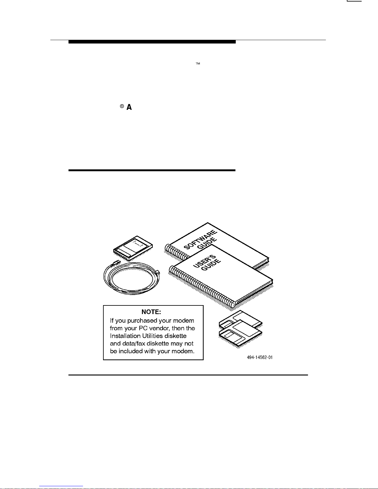
KeepInTouch PCMCIA
Modem Package
Figure 1-1 and the following sections describe what equipment
is supplied and what equipment is required to install and operate
the modem.
Figure 1-1. Supplied Equipment
Page 17

Introduction
1-3
Issue 2 May 1995
Supplied Equipment
The following hardware and software is included with the
modem:
G
One KeepInTouch PCMCIA modem
G
One user’s guide
G
A 2-pin modular telephone cord
The following items are optional and may not be packaged with
your modem:
G
A KITr Utilities diskette (high-density 3.5″) containing
software for installing, enabling, upgrading, and testing
your modem. The diskette also contains help text files
with information on using your modem and its AT
command set.
NOTE:
If your modem was included as part of your PC purchase,
then a KIT Utilities diskette may not have been provided
with the modem.
G
Diskettes and user’s guides for software which allows
you to send data and fax transmissions.
G
A technical information update sheet (if applicable).
Page 18

Introduction
1-4 Issue 2 May 1995
Additional Equipment You Will Need
The following additional hardware and software is necessary to
install and operate your modem.
G
A notebook or laptop personal computer that supports a
PCMCIA Type II socket.
G
If you did not receive a KIT Utilities diskette with your
modem, you will need Card and Socket Services that
comply with PCMCIA Release 2.1. These are PCMCIA
enablers (drivers) which should already be installed on
your PC.
G
Communications software that allows the PC to control
the modem (if not supplied with your modem). This
software application allows you to transfer files to and
from your PC, receive electronic mail (e-mail), dial into
bulletin boards, etc.
G
If you want to send and receive faxes, you will also need
fax application software (if not supplied with your
modem).
For connection to a normal telephone line you need:
G
A telephone outlet (RJ11C in the USA, CA11A in
Canada).
For connection to a cellular telephone (supported in Model 3766
only) you need:
G
A cellular telephone,
G
A Cellular Direct Connect Cable specific to your type and
model of cellular telephone. For more information about
equipment for cellular operation, refer to Appendix D,
Cellular Communications
.
Page 19

Introduction
1-5
Issue 2 May 1995
Where to Find
Additional Information
Help text files (also called “readme” files) contain supplemental
information, such as tutorials and AT command descriptions.
They may also contain information that is more recent than what
is printed in this user’s guide. Help text files are available
through the following sources:
G
KIT Utilities software. This software diskette may have
been packaged with your modem.
G
If you did not receive a KIT Utilities diskette and your
modem was included in a PC purchase, your PC vendor
may have loaded the files from the diskette onto the hard
drive for you. The main executable file for the KIT Utilities
is “KIT.EXE”.
G
A Bulletin Board System (BBS). Check to see if there is a
BBS telephone number
on your warranty card or other
enclosed documentation
. The BBS contains the latest
version of the KIT Utilities, which include the help text
files.
You can view the help text files either through the KIT Utilities or
with a text editor (the files are in ASCII format). Instructions for
installing the KIT Utilities and reading the help text files are
provided in Chapter 2, starting on page 2-4.
Where to Find Technical
Support Telephone Numbers
You may have access to a technical support center and BBS for
further assistance. Check your warranty card for the telephone
numbers for this support or the other supporting documentation
from your PC or modem vendor. The location of these telephone
numbers varies, depending on whether you purchased your
modem separately, or as part of a PC package.
NOTE:
The inside front cover of this user’s guide contains space
for recording technical support and BBS telephone
numbers.
Page 20
2-1
Issue 2 May 1995
Installation
2
Installing Your KeepInTouch
PCMCIA Modem
This section describes how to install your KeepInTouch PCMCIA
modem. Please take a minute to review these procedures before
installing your modem.
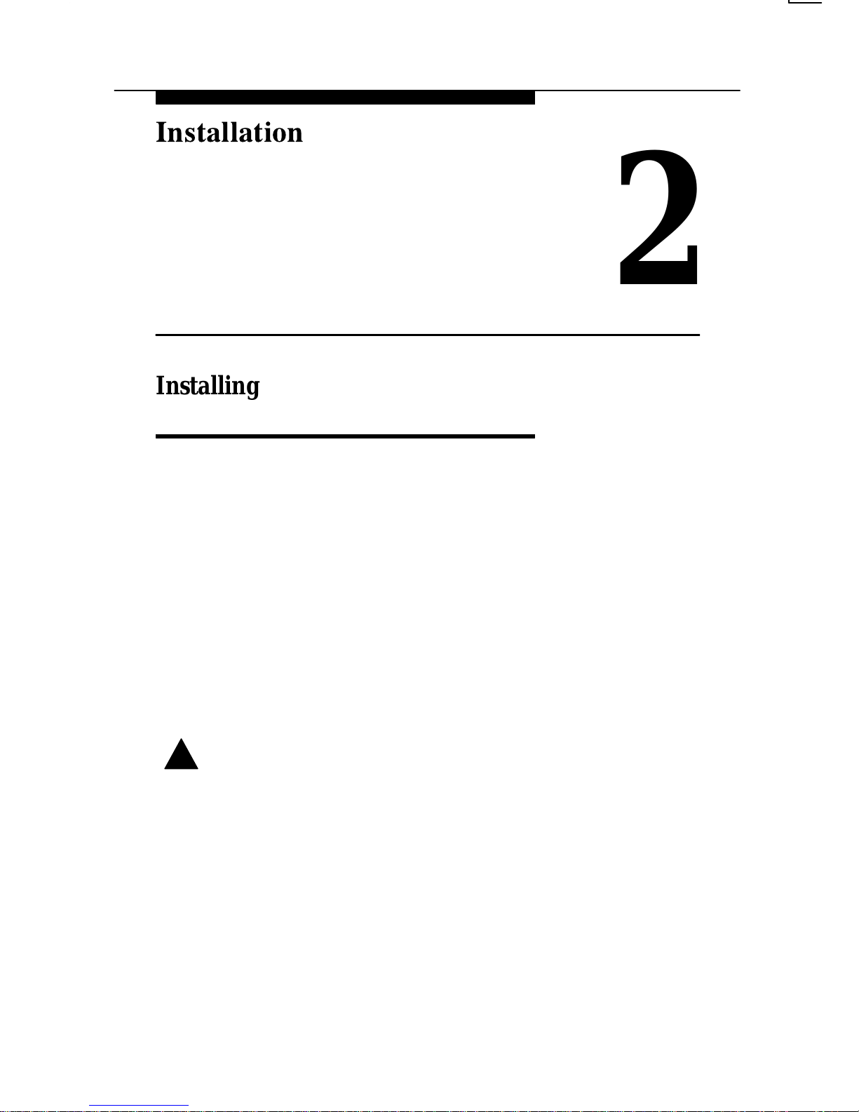
Use Figure 2-1 and the following steps to install your modem.
1. Locate an unused PCMCIA socket on your PC. Refer to your
PC’s user’s guide for more information about the PCMCIA
socket.
2. Hold the modem so that the product logo label is facing up,
and the 68-pin connector is facing the PCMCIA socket.
Insert the modem into the socket, pushing it all the way in so
that all 68 pins are engaged.
!
CAUTION:
Use care when inserting the modem into the socket.
Do not force the modem, as that may damage the pins on
the connector.
Page 21
Installation
2-2 Issue 2 May 1995
Figure 2-1. Modem Installation
Connection to a Telephone Outlet
If you intend to use regular (land-line) telephone lines, use this
procedure. If, however, you want to connect to a cellular
telephone (supported in Model 3766 only), refer to Appendix D,
Cellular Communications
.
1. Plug the modular cord’s 2-pin connector into the modem’s
2-pin rear edge connector. Since the 2-pin connector is not
keyed, it does not matter which way it is plugged in.
2. Next, plug the cord’s modular telephone plug into the
telephone jack.
Page 22

Installation
2-3
Issue 2 May 1995
!
CAUTION:
If you need to remove the modem from the PCMCIA socket,
be sure to unplug the modular cord’s 2-pin connector from
the modem before
removing the modem from the PC. Refer
to your PC’s documentation for instructions on removing the
modem from the socket.
Your modem is now installed in a PCMCIA slot on your PC. To
use the modem, however, your PC must be set up to recognize
the modem in that slot.
If KIT Utilities software was provided with your modem (either
on diskette or already copied onto your PC’s hard drive), your
next step is to install the KIT Utilities. The following section,
Using the KIT Utilities
, describes this process.
NOTE:
If your PC has Card and Socket Services installed, you
can use your modem
without
installing the KIT Utilities.
However, to upgrade your modem’s firmware or perform
diagnostics, you will need to install the KIT Utilities.
If you do
not
have KIT Utilities software, check your PC’s
documentation to ensure that there are PCMCIA card enablers,
also called Card and Socket Services, installed on your PC. With
Card and Socket Services, your modem should be automatically
recognized by the PC, in which case no further steps are
required – your modem will be ready to use with your
communications or fax software.
If you do not have card enablers on your PC and do not have
the KIT Utilities, or if the card enablers on your PC did not detect
the modem, contact your modem or PC vendor for assistance.
Page 23

Installation
2-4 Issue 2 May 1995
NOTE:
If you do not use the KIT Utilities to enable your modem,
the COM port and IRQ settings reserved for the modem
will be determined by the PCMCIA card enablers on your
PC. You need to know these values to set up your
communications and fax software applications.
Refer to
your PC’s documentation for information on where to find
the COM port and IRQ settings.
Using the KIT Utilities
With the KIT Utilities software you can set up your PC to use the
modem, perform diagnostic tests, and upgrade your modem with
new firmware. You can also view help text files on a variety of
topics, including how to use the KIT Utilities, modem tutorial
information, and AT command usage.
To use the Kit Utilities, first install the software on your PC. Once
installed, the KIT Utilities menus and messages guide you
through the available options and provide help along the way.
1. If you have a KIT Utilities diskette, insert it in your PC’s
floppy drive.
2. Be sure to use the KIT Utilities software while in a DOS
environment. If you are using Microsoft
r
Windows
t
, exit
from that program (Alt-F4) before continuing.
3. To load the KIT Utilities program
:
TYPE: a
:KIT
where
a
is the letter designated for your PC’s
floppy drive. Or, if you already have the KIT
Utilities loaded onto your PC’s hard drive, enter
the drive and path to the KIT.EXE program. For
example: C:\KIT\KIT
PRESS:
Enter
The Main Menu for the KIT Utilities appears on your screen.
You may want to select the “Help” option and read “Installing KIT
Utilities” before selecting the “Install KIT Utilities” option.
Page 24

Installation
2-5
Issue 2 May 1995
To select an option from a KIT Utilities menu, use the up and
down arrow keys or press the first letter of the menu item. A brief
description of each menu option is displayed as you scroll
through the list of options. After you select (highlight) the menu
option, press Enter.
NOTE:
The COM port and IRQ settings for your modem are
displayed on your PC monitor by the KIT Utilities software
when the modem is enabled. Record this information for
setting up your communications and fax software
applications.
Installing Fax Software
Some KeepInTouch PCMCIA modems ship with software that
allows you to send and receive faxes. Before installing any fax
software, make sure the modem is installed and configured in
your computer.
Follow the installation and operation instructions
that are packaged with your fax software.
For COM port and IRQ information, refer to your PC’s
documentation.
Additional information on using your modem for fax operation is
provided starting on page 3-14.
Page 25

3-1
Issue 2 May 1995
3
This chapter highlights some of the basic functions and
commands necessary to operate your modem. Whether you
consider yourself a novice or an experienced user in data
communications, you may want to read through some of the
examples to become familiar with your modem’s operation.
For information on more advanced concepts such as altering
data rates, error control, data compression, and flow control, see
Appendix E,
Advanced Modem Concepts
.
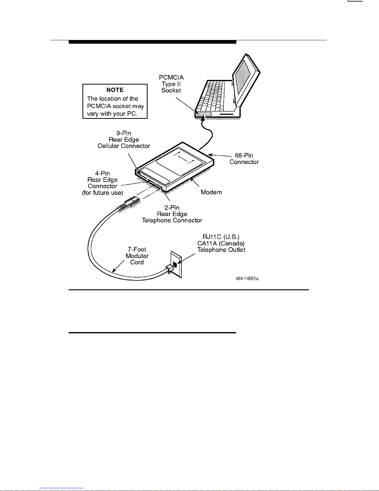
What is a Modem?
A modem is a piece of equipment that allows your computer to
communicate over telephone lines with other computers. Picture
the modem as a telephone for your computer — it performs
many of the same functions as a telephone, such as dialing,
answering calls, and hanging up.
Information is sent over telephone lines in a format called
analog
. Computers, however, communicate information in a
format called
digital
. The modem’s job is to translate the
information between the two formats. A modem converts digital
information from a computer into analog so that it can be sent
over a telephone line to another modem. The receiving modem
then translates the information back into a digital format so that
the receiving computer can use it (see Figure 3-1).
This process of modulating (converting digital to analog) and
demodulating (converting analog to digital) a signal gives us the
acronym, modem.
Page 26
Using Your Modem
3-2 Issue 2 May 1995
Figure 3-1. Dial Data Network
Understanding Your Modem’s
Operating Modes (Command
and Data)
Before a modem connects with another modem over a
telephone line, it is in Command mode. Command mode is an
idle state where you can enter commands to change how the
modem functions or to cause the modem to perform an action,
such as dialing a telephone number. You send commands to
your modem by using a communications software package and
your computer’s keyboard.
Once two modems are connected (also known as ‘online’), they
automatically switch to Data mode. In Data mode, any
information sent from the computer to the modem is
data
(as
opposed to a
command
) and is transferred to the remote
modem. The two modems stay in Data mode until the
connection is broken or until they are forced into online
Command mode using the escape sequence (described
below). When the modem is in online Command mode, you can
enter commands to the modem, without your entries being
mistaken for data. (The connection between the two modems is
not broken.)
Page 27

Using Your Modem
3-3
Issue 2 May 1995
The escape sequence is a series of characters (usually ‘+++’)
that you type in to switch from Data mode to online Command
mode. Use the escape sequence when you want to enter a
command to the modem while it is in Data mode. Think of the
escape sequence as a way to get the modem’s attention when it
is busy sending or receiving data. For more information on the
escape sequence, see page 3-9.
Using AT Commands
The KeepInTouch PCMCIA modem uses AT commands and
S-Registers to control its operation. These commands are
issued to your modem from your computer through a
communications software package.
Before you can enter commands to your modem, make sure you
have installed the modem in the computer as described in
Chapter 2,
Installation
, and that you have a communications
software package installed and running on your computer. The
software must be set up to recognize your modem. Refer to your
communication software’s documentation for more information.
To use AT commands, the modem must be in either Command
mode or online Command mode. If the modem is in Data mode,
you need to enter the escape sequence (+++) to switch to
Command mode (see page 3-9) before entering a command.
Please review the following guidelines before using any
AT commands.
G
All commands (except A/ (which repeats the last
command) and +++ (the escape sequence)) must begin
with the characters AT and end by pressing the Enter
key.
G
The AT (or at) prefix (which means attention) can be
upper- or lowercase, but the modem will not recognize
mixed case prefixes (do not use ‘At’ or ‘aT’).
Page 28

Using Your Modem
3-4 Issue 2 May 1995
G
The data character format for the AT command set must
be one of the following. It can be set using your
communications software:
— 8 data bits + no parity + 1 stop bit.
— 7 data bits + no parity + 2 stop bits.
— 7 data bits + parity + 1 stop bit (parity can be
odd, even, mark, or space).
G
S-Registers also require the AT prefix. To change an
S-Register, use the ATS
n=x
command, where n is the
number of the S-Register and
x
is the new value to be
stored in that register. S-Registers are described in
Table 4-2 which begins on page 4-20.
G
Commands can be entered one at a time or in strings
(several commands at once – for example,
AT&FS0=0&W). Strings can have up to 60 characters
after the AT prefix.
G
Commands described in this manual that end with the
suffix
n
have several options associated with them. For
example, in the &T
n
command, &T6 causes the modem
to perform a remote digital loopback test while &T8
causes the modem to perform a local loopback test with
patterned data. If no value is entered for the
n
variable,
the modem assumes a default value of zero (0) for
n
.
G
Commands are acknowledged by the modem with
responses, such as OK or ERROR. These are known as
response codes, which are described in Appendix C.
NOTE:
All commands supported by your modem are described in
Chapter 4,
AT Command Set and S-Registers
.
Page 29
Using Your Modem
3-5
Issue 2 May 1995
Making a Call
with Your Modem
The dial command (D) is used to place a call. When the modem
receives this command, it goes off-hook and connects the
modem to the phone line so that a call can be made (similar to
picking up a telephone’s handset), and dials the telephone
number specified in the command string.
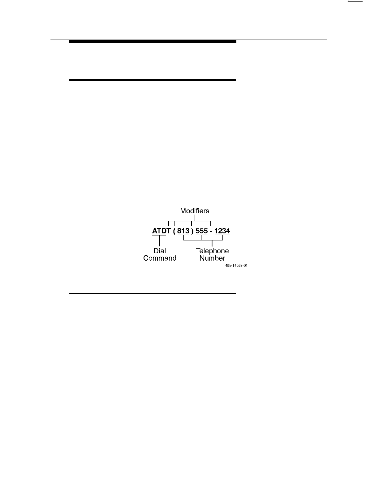
Dial Command Strings contain the AT prefix, the dial
command (D), optional dial modifiers, and the telephone
number. A dial modifier tells the modem to perform additional
tasks when dialing a telephone number.
The following example shows the elements of a dial command
string:
Dial Modifiers
The following can be used as dial modifiers:
T – Touch-Tone Dialing. Any digit 0–9, * , # , A, B, C, or D can
be dialed as tone.
P – Pulse Dialing. Only the digits 0–9 can be dialed in Pulse
Dial mode.
- , ( ), and Space. These characters are ignored by the dial
string and can be included in the dial string to enhance
readability.
, – Pause. Causes the modem to pause before processing the
next character in the dial string. The length of this pause is
determined by the value held in S-Register S8, the Pause Time
configuration option.
Page 30

Using Your Modem
3-6 Issue 2 May 1995
W – Wait for Dial Tone. The modem waits for a specified time
before expecting a second dial tone, then begins processing the
dial string. For example, if you must dial a 9 to reach an outside
telephone line, the W modifier delays the modem from dialing
until it receives a second dial tone for the outside line. The
amount of time the modem waits is determined by the setting of
S-Register S6. Once a dial tone is detected, or if the time period
runs out, the modem then processes the next command in the
dial string. If a busy signal is detected, the modem responds with
a busy response code and then goes into off-line command
mode.
R – Reverse Originate Mode. Places the modem in answer
mode. This modifier is used when calling an ‘originate-only’
modem. This modifier is the last character in the dialing string
(e.g., ATDT 123-4567R).
S=
n –
Dial Stored Telephone Number. Causes the modem to
dial the telephone number which was previously stored in
memory by an &Z command.
@ – Wait for Quiet Answer. The modem will wait for a specified
amount of time (determined by S-Register S7), followed by five
seconds of silence before processing the next dial modifier. If
the silence is not detected, the modem sends a NO ANSWER
result to the computer.
! – Hook Flash. Causes the modem to go on-hook for
0.5 seconds. This modifier inserts a short on-hook time, typically
used for transferring a call.
; – Return to Command Mode. Modem returns to Command
mode after dialing a number without disconnecting the call. This
allows AT command strings that exceed the 60 character limit to
be linked together and is useful when using a calling card
number or an international telephone number.
Page 31

Using Your Modem
3-7
Issue 2 May 1995
Examples of Dial Command Strings
Local Call using Tone Dialing
In this example, D is the dial command, T is the Tone dialing
modifier, and
555-1234
is the telephone number.
TYPE:
ATDT 5551234
PRESS:
Enter
Calling through a Private Branch Exchange (PBX)
In this example, Tone dialing is selected, a 9 is dialed to pass
through the PBX (to get an “outside” line), the modem waits for a
dial tone (due to the
W
modifier), and then dials the telephone
number
555-1234
.
TYPE:
ATDT9W555-1234
PRESS:
Enter
Dialing a Stored Telephone Number
This example shows how to dial a number which has been
stored in the memory of the modem. You can use the &Z
command to store up to four different telephone numbers in
memory. In this case, the modem will dial the number stored in
memory location 2. For more information on &Z, see page 4-17.
TYPE:
ATDS=2
PRESS:
Enter
Calling Long Distance
This is another example of using Tone dialing, this time to place
a long distance call. The spaces, parentheses, and dashes are
used to make the number easier to read, but are ignored by the
modem.
TYPE:
ATDT 1 (813) 555-1234
PRESS:
Enter
Page 32

Using Your Modem
3-8 Issue 2 May 1995
If you would like to know more about the function of the dial
command, refer to the following commands in Chapter 4:
P (Pulse Dial), T (Tone Dial), &Z (Store Telephone Number),
S6 (Blind Dial Pause Time), S7 (No Answer Time-out), and
S8 (Pause Time Dial Modifier).
Disconnecting a Call
Use either the H command or DTR disconnect to disconnect a
call.
To disconnect using the H command, use the escape sequence
to enter online Command mode, then issue an H command to
make your modem hang up, or go on-hook.
TYPE:
+++
To exit Data mode and enter online Command
mode. (The +++ is an escape sequence, described
on pages 3-3 and 3-9.)
TYPE:
ATH
To issue the command to hang up.
PRESS:
Enter
The modem disconnects.
The second, and more subtle, approach to hanging up a call is
to make sure that the &D command is set to &D2 (the factory
setting). This allows your communications software to drop the
DTR signal to the modem and force the modem to disconnect
the call. This method is often used by communications software.
Also note that your modem automatically disconnects when the
remote modem hangs up.
If you would like to know more about disconnecting a call, refer
to the following commands in Chapter 4: +++ (escape
sequence), O (Return to Online Data Mode), X (Extended
Response Codes, Dial Tone Detect, Busy Tone Detect),
&D (DTR Control), \N (Set Error Control Mode), \T (Set Inactivity
Timer), S7 (No Answer Time-out), and S10 (No Carrier
Disconnect).
Page 33

Using Your Modem
3-9
Issue 2 May 1995
Manually Answering a Call
The best way to answer a call is to set the Auto-Answer Ring
Number register (S0) to 1 or more rings. To enable this feature,
set the value of S0 to 1 or more rings.
If S0 = 0 (which is the setting from the factory), use the A
command to manually answer incoming calls, as follows:
TYPE:
ATA (after the modem rings)
PRESS:
Enter
NOTE:
DTR must be present (activated by the communications
software) for the modem to answer the call.
Using the Escape Sequence —
Switching Between Data Mode
and Online Command Mode
To enter online Command mode while in Data mode, use the
escape sequence, which consists of three plus signs (+++).
When typing the escape sequence, you must allow some
amount of idle time before and after typing the + signs. This
amount of time is called the escape guard time. For example, if
the escape guard time is set for one second (the setting from the
factory), you must allow at least one second of idle time (no data
being transferred) before typing the first + sign, and at least one
second after typing the last + sign, before the modem will be in
online Command mode. Further, you must not wait more than
one second between typing each of the three + signs.
This idle time before and after the escape sequence prevents
the escape sequence characters from being misinterpreted as
part of the data stream being sent between the modems.
To enter the escape sequence:
TYPE:
+++
Do not press the Enter key. The modem enters
online Command mode and responds with an OK.
Page 34

Using Your Modem
3-10 Issue 2 May 1995
NOTE:
The escape sequence character (+) and the escape guard
time are determined by the S2 and S12 registers,
respectively. To change these values, refer to the
descriptions of these S-Registers in Chapter 4.
For more information on Command and Data modes, see
page 3-2.
To return to Data mode from online Command mode, use the
O command, as follows:
TYPE:
ATO
PRESS:
Enter
Viewing, Saving, and
Loading Modem Settings
Modem settings determine how the modem functions. These
settings are stored in two permanent memory areas, User
Profile 0 and User Profile 1.
When the modem is first turned on, the contents of one of the
two memory areas are retrieved into an area of memory known
as the Active Profile. (The &Y command determines which of
the two user profiles will be retrieved.) The Active Profile is
stored in volatile memory, which means that the contents of that
area are
not
saved when the modem is powered off. If you make
changes to the modem’s configuration and then turn the modem
off without saving those changes, they are lost forever.
User Profile 0 and User Profile 1, however, are stored in
nonvolatile memory areas. Nonvolatile memory is saved even if
the modem is turned off. If your modem requires a particular
configuration to work with an application, then those options
should be set and saved to one of the two nonvolatile memory
areas using the &W command.
Page 35

Using Your Modem
3-11
Issue 2 May 1995
View Active and Stored User Profiles
Command (&V)
The &V command displays a summary of the modem’s Active
Profile, either User Profile 0 or User Profile 1, and any telephone
numbers saved by the &Z command.
To use the &V command:
TYPE:
AT&V
n
where n is
0 to view the Active Profile, User Profile 0, and any
stored telephone numbers.
1 to view the Active Profile, User Profile 1, and any
stored telephone numbers.
PRESS:
Enter
Save (Write to Memory)
Command (&W)
After you make changes to the modem’s configuration options,
you can save your changes in either the User Profile 0 or User
Profile 1 memory area by using the &W command. (Remember
that the Active Profile is a
temporary
work area for your modem.
A loss of power or a reset discards any changes made in the
Active area.)
To use the &W command:
TYPE:
AT&W
n
where n is 0 for User Profile 0 and 1 for User
Profile 1.
PRESS:
Enter
The changes are saved and the modem responds
with an OK.
Page 36

Using Your Modem
3-12 Issue 2 May 1995
Reload Factory Settings Command (&F)
The modem ships from the factory ready to operate with your
computer and transfer data over a normal telephone line. If you
have changed several configuration options that no longer apply
to what you want to do, you can reload the original factory
template with the &F command.
To use the &F command:
TYPE:
AT&F
PRESS:
Enter
The factory settings are loaded into the Active User Profile and
the modem is set up for Data mode.
These are some of the features and functions available to you
when the factory settings are loaded:
G
V.34 operation with a dial line data rate of 28,800 bps.
G
V.42bis data compression when using V.42 error
correction.
G
MNP 5 data compression when using MNP error
correction.
G
Hardware (RTS/CTS) flow control.
G
CD and DTR set for standard RS232 operation.
G
DSR forced on.
G
Response codes enabled, displayed as words (not
numbers).
G
V.34 Automoding, which allows the modem to connect
with non-V.34 modems.
G
Busy and Dial tone detection enabled.
Page 37

Using Your Modem
3-13
Issue 2 May 1995
Reload Settings from a User Profile (&Y)
Use the &Y command to select whether the contents of either
User Profile 0 or User Profile 1 are loaded into Active memory
each time the modem turns on or when a reset command (Z) is
issued.
To use the &Y command:
TYPE:
AT&Y
n
where n is 0 for User Profile 0, or 1 for User
Profile 1.
PRESS:
Enter
Reset Modem and Load User Profile (Z)
Use the Z command to reset the modem and load the contents
of User Profile 0 or User Profile 1 into the the modem’s Active
memory area.
To use the Z command:
TYPE:
ATZ
n
where n is 0 for User Profile 0, or 1 for User
Profile 1.
PRESS:
Enter
The Z command must be the last command in the command
string, because any commands after it will be ignored.
Page 38

Using Your Modem
3-14 Issue 2 May 1995
An Overview of File Transfers
and Fax Operation
The purpose of this section is to make you aware of the basic
concepts involved when using your modem to transfer and
receive files and fax messages. For information on how to use
your communication or fax software, refer to the
documentation provided with your software package.
File Transfers
Two terms essential to file transfers are download and upload.
A download occurs when you want to receive a file
from
a host
site (such as a BBS or another computer). An upload occurs
when you want to send a file
to
a host site. However, before you
can do this, you must:
G
Have your modem and PC set up for modem operation
before executing your communications software.
G
Have communications software that is operating and in
terminal mode.
G
Have your modem online with another modem.
G
Determine whether you want to upload or download files.
G
Verify that the character format (7 data bits, odd parity,
1 stop bit; 8 data bits, no parity, 1 stop bit; and so on) is
the same for both the local and remote modems.
G
Select a file transfer protocol (ZMODEM, YMODEM,
XMODEM, Kermit, and so on) that is compatible with
your communications software and remote system.
Some protocols require simultaneous actions at both
ends of the link to start a transfer, while others permit
initiation of the transfer from one side only.
NOTE:
ZMODEM protocol is recommended for its speed and
reliability, if your software supports this protocol.
Page 39

Using Your Modem
3-15
Issue 2 May 1995
A file transfer protocol sets the ground rules that your modem
and the remote system use to move files back and forth. Check
your communications software manual for descriptions of the
various protocols it supports; the software program usually walks
you through the download/upload process.
Fax Operation
Fax software essentially turns your computer and modem into a
fax machine, allowing you to send a file to or receive a file from
another fax modem or fax machine.
If you have a scanner, any image can be scanned in and
converted to a data file which may then be faxed to either a
remote fax machine or to another PC. Also, documents created
on your PC can typically be faxed to a remote fax machine or
PC.
Similar to your communications software, your fax software uses
basic AT commands for functions such as dialing and answering
calls and for speaker control and adjustments. Refer to your
communication software’s user’s guide for more information on
AT command support.
Before sending or receiving a fax, verify the following:
G
Your modem and PC must be configured for modem
operation before executing your fax software.
G
You must have fax software installed and operating on
your PC.
G
Some fax software packages require the modem to have
Auto-Answer disabled (S0 = 0) to receive a fax.
G
Some fax software packages require that the modem use
software flow control (\Q1) to send and receive a fax.
Refer to your fax software documentation for more on fax
operation.
Page 40

Using Your Modem
3-16 Issue 2 May 1995
Using Hayes AutoSync
The Hayes AutoSync feature allows your modem to establish a
call between an asynchronous computer and a synchronous
mainframe computer. The advantage of this is that it eliminates
the need for a synchronous interface card in your PC.
To use this feature, a Hayes AutoSync communications
package, such as EXTRA!r Extended for DOSr by Attachmate,
must be used. The &M option, described on page 4-13, must be
set to &M4 when using Hayes AutoSync.
After using the Hayes AutoSync feature, it is recommended that
you reload your modem’s original configuration settings to avoid
possible conflicts during normal modem operation. Use the &F
command to reload the factory settings. The &F command is
described
on pages 3-12 and 4-12.
Using Cellular Channels
KeepInTouch Model 3766 modems can be connected to
selected cellular telephones. For more information on cellular
operation, refer to Appendix D,
Cellular Communications
.
Page 41

4-1
Issue 2 May 1995
4
AT Commands and S-Registers
This chapter provides a list of all AT commands and S-Registers
supported by the KeepInTouch PCMCIA modem.
In general, AT commands are responsible for instructing the
modem to do a task, such as dialing, hanging-up, loading factory
default settings, etc. However, some AT commands, and most
S-Registers, are responsible for setting configuration options
which determine
how
the modem operates. You issue these
commands to your modem via your communications software.
When a modem receives a command, it responds with a
message, known as a response code, that displays on your
monitor. Response codes are described in Appendix C.
For a brief overview of command guidelines, refer to the
Using
AT Commands
section in Chapter 3,
Using Y our Modem
.
The AT commands supported by the modem are described in
Table 4-1. S-Registers are described in Table 4-2, which begins
on page 4-20. Factory settings are listed in bold.
NOTE:
Use only those commands and S-Registers that are
described in this chapter. Entry of any other commands or
S-Registers is not supported and may produce
unpredictable results.
Page 42

AT Command Set and S-Registers
4-2 Issue 2 May 1995
Table 4-1. AT Command Reference (1 of 18)
AT
Command
Description
+++ ESCAPE SEQUENCE
The escape sequence allows the modem to exit Data mode
and enter online Command mode. For more information on
using this command, see page 3-9.
A/ REPEAT LAST COMMAND
This command re-executes the last ‘AT’ command string
stored in the command buffer. The A/ command is the only
command not preceded by ‘AT’ and ended by a carriage
return.
A ANSWER COMMAND
This command allows the modem to go off-hook and answer
an incoming call.
B
n
CCITT/BELL MODE
This command selects a CCITT or Bell communications
standard. When CCITT V.23 is selected, this command also
selects the send and receive data rates.
For more information, refer to the %B command,
S-Registers S76 and S78, and Appendix E,
Advanced
Modem Concepts.
B0 Selects CCITT V.22 when the modem is at
1200 bps, and CCITT V.21 when the modem
is at 300 bps.
B1 Selects Bell
212A when the modem is at
1200 bps, and Bell 103 when the modem is at
300 bps.
B2 Selects CCITT V.23. Modem receives at 1200 bps
and transmit at 75 bps when in originate mode.
Modem receives at 75 bps and transmits at 75 bps
when in answer mode.
B3 Selects CCITT V.23. Modem receives at 75 bps and
transmits at 75 bps when in originate mode. Modem
receives at 1200 bps and transmit at 75 bps when in
answer mode.
Page 43

AT Command Set and S-Registers
4-3
Issue 2 May 1995
Table 4-1. AT Command Reference (2 of 18)
AT
Command
Description
D DIAL
This command causes the modem to immediately go
off-hook and dial a telephone number with corresponding
dial modifiers. Dial modifiers are parameters that define how
the modem should dial the telephone number.
0–9 Dialing digits
A,B,C,D, *, # Tone Dial Characters
P Pulse Dial — Configures the modem to use pulse
dialing to dial a telephone number. Only digits 0–9
can be dialed.
R Reverse Originate Mode — Places the modem in
answer mode. This modifier should be the last
character in the dialing string
(e.g., ATDT 123-4567R)
S=n Dial Stored Telephone Number — Causes the
modem to dial a telephone number that has been
previously stored in the modem’s memory with the
AT&Zn=x command.
T Tone Dial — Configures the mode to use DTMF
tones to dial a telephone number.
W Wait for Dial Tone — Causes the modem to wait for
a dial tone.
, Pause — Causes the modem to pause or delay
implementing the next parameter in the dial string by
the time specified in S-Register S8
.
! Flash Hook — Causes the modem to go on-hook for
0.5 seconds.
@ Wait for Quiet Answer — Causes the modem to wait
5 seconds after dialing and detecting ring-back
before processing the next dial modifier.
; Return to Command mode — Allows AT command
strings that exceed the 60-character limit to be linked
together. This is useful for dialing very long numbers,
such as for international or credit card calls.
– ( ) Ignored by Modem — These characters (dash, open
and close parentheses) are ignored by the modem,
but may be included in the dial string for separating
area codes and numbers. Spaces are also ignored in
the dial string.
Page 44

AT Command Set and S-Registers
4-4 Issue 2 May 1995
Table 4-1. AT Command Reference (3 of 18)
AT
Command
Description
E
n
COMMAND CHARACTER ECHO
This command controls whether or not the characters you
enter from your computer’s keyboard are echoed back to
your monitor when the modem is in Command mode.
E0 Disables echo.
E1 Enables echo.
H
n
HOOK
This command lets the modem go on-hook to disconnect a
call or off-hook to make the telephone line busy.
H0 The modem goes on-hook (disconnects a call).
H1 The modem goes off-hook.
I
n
MODEM IDENTIFICATION
This command displays information about your modem.
I0 Displays product code “240”.
I1 Displays firmware revision number (first three digits
only, see I19 for full display).
I2 Performs a checksum, which verifies the integrity of
the firmware running in your modem.
I19 Displays the version number of the firmware running
in the modem.
M
n
SPEAKER ON/OFF CONTROL
M0 Speaker always off.
M1 Speaker on until carrier signal becomes active.
M2 Speaker always on.
M3 Speaker off during dialing and on until carrier signal
becomes active.
O RETURN TO ONLINE DATA MODE
This command allows you to exit Online Command mode
and return to Data mode.
P PULSE DIAL (Used with rotary telephone lines)
This command configures the modem for Pulse dialing. To
disable Pulse dialing issue the T (tone dial) command. Tone
dialing is the default factory setting.
Page 45

AT Command Set and S-Registers
4-5
Issue 2 May 1995
Table 4-1. AT Command Reference (4 of 18)
AT
Command
Description
Q
n
RESPONSE CODES
This command determines whether or not the modem will
send response codes to the computer.
Q0 Enables response codes.
Q1 Disables response codes.
Sn=
x
CHANGE S-REGISTER
This command is used to change the value of an S-Register.
S-Registers are described in Table 4-2, which begins on
page 4-20.
n
= the number of the S-Register you want to change.
x
= the new value for S-Register
n,
in decimal format.
Sn? VIEW S-REGISTER
This command displays the contents of an S-Register
(in decimal format).
n
= S-Register to be displayed.
T TONE DIAL (Touch-tone dialing method)
This command configures the modem for touch-tone dialing.
This is the default dialing method.
V
n
RESPONSE CODES FORMAT
This command controls whether response codes appear as
words (such as OK or CONNECT) or as numbers (such as 0
or 1).
V0 Displays as numbers.
V1 Displays as words.
Page 46

AT Command Set and S-Registers
4-6 Issue 2 May 1995
Table 4-1. AT Command Reference (5 of 18)
AT
Command
Description
X
n
EXTENDED RESPONSE CODES, DIAL TONE DETECT,
BUSY TONE DETECT
This command controls three different configuration options.
Extended Response Codes allow additional information to
be displayed in response code messages.
When
disabled,
only Basic response codes (OK,
CONNECT, RING, NO CARRIER, and ERROR) are
displayed. Use X0 to disable extended result codes.
When Extended response codes are
enabled
, CONNECT
messages include the data rate, and may also be set to
include information on error control and data compression.
Extended result codes also report reasons why a connection
failed, such as NO ANSWER, BUSY, and NO DIALTONE.
Use X1–X7 to enable extended response codes. For more
information on response codes, refer to Appendix C.
Dial Tone Detect
, if enabled, causes the modem to wait (up
to the time set in S7) for a dial tone before dialing. If
disabled, the modem dials the call regardless of dial tone
detection (also known as blind dialing).
Busy Tone Detect
, if enabled, sets the modem to monitor for
a busy tone. If disabled, the modem ignores busy tones.
(continued on next page)
Page 47

AT Command Set and S-Registers
4-7
Issue 2 May 1995
Table 4-1. AT Command Reference (6 of 18)
AT
Command
Description
X
n
(continued)
Extended Dial Tone Busy Tone
Response Codes Detect Detect
X0 Disabled Disabled Disabled
(CONNECT)
X1 Enabled Disabled Disabled
(CONNECT line rate)
X2 Enabled Enabled Disabled
(CONNECT line rate)
X3 Enabled Disabled Enabled
(CONNECT line rate)
X4 Enabled Enabled Enabled
(CONNECT line rate)
X5 Enabled Enabled Enabled
(CONNECT line rate/REL)
X6 Enabled Enabled Enabled
(CONNECT line rate protocol)
X7 Enabled Enabled Enabled
(CONNECT dte rate)
Z
n
RESET AND LOAD STORED PROFILE
This command causes the modem to go on-hook (hang-up),
performs a warm reset, and then load a User Profile (which
has been previously stored in the modem’s memory) into the
Active Profile. This command is last in a command string
because all subsequent commands are ignored.
Z0 Resets the modem and loads User Profile 0 options
into the Active profile.
Z1 Resets the modem and loads User Profile 1 options
into the Active profile.
Page 48

AT Command Set and S-Registers
4-8 Issue 2 May 1995
Table 4-1. AT Command Reference (7 of 18)
AT
Command
Description
\A
n
MAXIMUM FRAME SIZE
This command determines the maximum frame (or block)
size used for V.42 or MNP error control operation. If the
telephone connection is poor, a smaller frame size may
improve the modem’s performance.
\A0 64 characters per frame
\A1 128 characters per frame
\A2 192 characters per frame
\A3 256 characters per frame
\A4 32 characters per frame
\A5 16 characters per frame
\C
n
SET AUTO-RELIABLE BUFFERING
This command determines whether or not the modem
buffers data received while it is negotiating the type of
connection to be used with a remote modem. Buffering
means the data is held in a temporary storage area until it
can be processed.
Online changes to this modem setting do not take effect until
a disconnect occurs.
\C0 Disabled. No data buffering is performed.
\C1 Enabled. Data is buffered until the connection
between the two modems has been established.
\C2 Disabled, switches after fallback character. No data
buffering is performed while the connection is being
established. The modem switches to normal mode
upon receipt of the auto-reliable fallback character
(set by the %A command) and passes it to the serial
port.
Page 49

AT Command Set and S-Registers
4-9
Issue 2 May 1995
Table 4-1. AT Command Reference (8 of 18)
AT
Command
Description
\G
n
MODEM-TO-MODEM FLOW CONTROL
In normal mode (set by the \N0 command or after fallback),
this command enables modem-to-modem flow control using
XOFF and XON characters to stop and start transmission
between modems, respectively.
For more information on flow control, refer to the \Q and \X
commands. Flow control is also described in Appendix E,
Advanced Modem Concepts
, starting on page E-4.
\G0 Disables modem-to-modem flow control.
\G1 Sets flow control to XON/XOFF.
\K
n
SET BREAK CONTROL
This command defines what action the modem takes when
a break (Attention signal) is sent or received, as described
below.
NOTE: Using this command is not recommended unless
your communications software supports the Break character
and your application requires you to send or receive break
signals.
This command controls three different actions the modem
may take when sending or receiving a break signal.
First, the command controls what is sent from the modem
first, any data which may be in the buffer, or the received
break. (When the break is sent first, this is sometimes
referred to as “expedited” mode.)
Second, the command controls whether or not any data in
the buffer is sent or discarded when the computer
sends
a
break. (When the data is discarded, this is sometimes
referred to as “destructive” mode.)
Third, the command determines whether or not the modem
enters Command mode when it receives a break from the
computer.
Send Send Enter
Data First?
Data? Command mode?
\K0 no no yes
\K1 no no no
\K2 no yes yes
\K3 no yes no
\K4 yes yes yes
\K5 yes yes no
Page 50

AT Command Set and S-Registers
4-10 Issue 2 May 1995
Table 4-1. AT Command Reference (9 of 18)
AT
Command
Description
\N
n
SET ERROR CONTROL MODE
This command determines the type of connection attempted
by the modem. If this command is entered while in online
Command mode, the changes will not take effect until the
next time a connection is established.
\N0 Normal Mode (Buffered Mode) — No data
compression or error control, but does use flow
control. The data is buffered. This mode can be used
when your communications package provides its
own error control, or if errors in the data are
acceptable. Normal mode can be used even if the
remote modem is set for Direct mode.
\N1 Direct Mode — No data compression, error control,
or flow control. The data is not buffered. Errors in the
data transmission may occur. The DTE
(PC-to-modem) speed must match the
modem-to-modem speed.
\N2 MNP or Disconnect (Reliable Mode) — The modem
attempts to connect using MNP error control,
hanging up if it fails.
\N4 V.42 or Disconnect (Reliable Mode) — The modem
attempts to connect using V.42 LAPM error control,
hanging up if it fails.
\N6 V.42 or MNP or Disconnect (Reliable Mode) — The
modem attempts to connect using V.42 LAPM error
control. If a V.42 LAPM connection fails, the modem
attempts to connect using MNP. If the modem cannot
connect using MNP, the connection fails.
\N7 V.42 or MNP or Normal (Auto-reliable Mode) — The
modem attempts to connect using V.42 LAPM error
control. If a V.42 LAPM connection fails, the modem
attempts to connect using MNP. If the modem cannot
connect using MNP, it will connect using Normal
mode.
\N8 Use \N4 (V.42 or Disconnect) for 4800 bps or
higher. Use \N7 (V.42 or MNP or Normal) for
2400 bps or lower.
Page 51

AT Command Set and S-Registers
4-11
Issue 2 May 1995
Table 4-1. AT Command Reference (10 of 18)
AT
Command
Description
\Q
n
SET SERIAL PORT FLOW CONTROL
This command specifies the DTE-to-modem flow control.
Software flow control uses the XOFF and XON characters to
stop and start data transmission, respectively, both to and
from the DTE.
One-way hardware flow control uses the CTS (Clear to
Send) signal to stop/start data from the DTE only, while
two-way hardware flow control also uses the RTS (Request
to Send) signal to start data from the modem.
For more information on flow control, also refer to the \G and
\X commands. Flow control is also described in Appendix E,
Advanced Modem Concepts
, starting on page NO TAG.
\Q0 Disables flow control.
\Q1 Enables software flow control (XON/XOFF).
\Q2 Enables one-way hardware flow control (CTS).
\Q3 Enables two-way hardware flow control
(RTS/CTS).
\T
n
SET INACTIVITY TIMER
This command forces the modem to disconnect if no data is
transmitted or received within a specified time period. This
timer applies only if the modem is not in Direct mode (\N1).
\T0 Disables inactivity timer.
\T1–90 Length in minutes.
\X
n
XON/XOFF PASSTHROUGH FLOW CONTROL
This command controls whether or not the modem passes
XON/XOFF characters from the locally attached computer
through to the remote modem.
This command is ignored if the modem is connected in an
error control mode (see \N), as the error control protocol
provides its own flow control.
For more information on flow control, also refer to the \G and
\Q commands. Flow control is also described in Appendix E,
Advanced Modem Concepts
, starting on page NO TAG.
\X0 Processes flow control characters and removes
them from the data stream.
\X1 Processes flow control characters and passes them
through to the local or remote modem to be
processed.
Page 52

AT Command Set and S-Registers
4-12 Issue 2 May 1995
Table 4-1. AT Command Reference (11 of 18)
AT
Command
Description
&C
n
CD CONTROL
This command controls the CD (Carrier Detect) signal.
&C0 State of carrier from the remote modem is ignored.
CD is always on. (Also known as Forced On.)
&C1 State of carrier from the remote modem is
tracked. CD reflects the state of the received
carrier. (Standard RS232 operation.)
&D
n
DTR CONTROL
This command controls what actions are taken by the
modem based upon the DTR (Data Terminal Ready) signal.
&D0 The modem ignores DTR and assumes it is always
active.
&D1 The modem switches from Data mode to Command
mode when an on-to-off transition of DTR is
detected. (An ATO returns the modem to Data
mode.)
&D2 The modem hangs up and switches to Command
mode when an on-to-off DTR transition is
detected. Auto-answer is disabled if DTR is low.
&D3 An on-to-off transition of DTR re-initializes the
modem but does not perform a complete power
reset.
NOTE: DTR has to remain off for a minimum amount of time
before the modem will perform any of the actions for this
command. This minimum time period is determined by the
setting of S-Register S25. If DTR is off for less than that time
period, no action is taken. See S25 for more information.
&F LOAD FACTORY SETTINGS
This command loads the factory settings for the AT
commands and S-Registers into the Active Profile area.
NOTE: This command does not reset the )Cn command
option to its factory setting.
Page 53

AT Command Set and S-Registers
4-13
Issue 2 May 1995
Table 4-1. AT Command Reference (12 of 18)
AT
Command
Description
&G
n
GUARD TONE
This command determines whether guard tones are sent out
while the modem is connected to a remote modem.
Guard tones are not used in North America but are
mandatory in some countries outside of North America.
Guard tones are only sent in V22 and V22bis modes.
&G0 Disables guard tone.
&G1 Enables 550 Hz guard tone.
&G2 Enables 1800 Hz guard tone.
&I
n
TRANSMIT LEVEL
This command sets the power level used by the modem to
transmit data over the telephone line. The transmit output
level can range from –10 dBm to –25 dBm.
I&10 = –10 dBm &I18 = –18 dBm
I&11 = –11 dBm &I19 = –19 dBm
I&12 = –12 dBm &I20 = –20 dBm
I&13 = –13 dBm &I21 = –21 dBm
I&14 = –14 dBm &I22 = –22 dBm
I&15 = –15 dBm &I23 = –23 dBm
I&16 = –16 dBm &I24 = –24 dBm
I&17 = –17 dBm &I25 = –25 dBm
&M
n
SELECT ASYNC OR AUTOSYNC MODE
This command selects the communication mode used by
your modem.
Async mode is appropriate for typical modem use.
Hayes AutoSync requires you to use communications
software which supports this feature. Refer to page 3-16 for
more information on Hayes AutoSync.
&M0 Enables Async mode.
&M4 Enables Hayes AutoSync. This command is normally
used
only
by your communications software.
Page 54

AT Command Set and S-Registers
4-14 Issue 2 May 1995
Table 4-1. AT Command Reference (13 of 18)
AT
Command
Description
&P
n
DIAL PULSE RATIO
This command determines the make/break
(off-hook/on-hook) ratio during pulse dialing.
&P0 Make = 39%, Break = 61%
(for use in the United States).
&P1 Make = 33%, Break = 67%
(not recommended for use in the United States).
&Q This command is the same as the &M command.
&S
n
DSR CONTROL
This command controls the DSR (Data Set Ready) signal
output from the modem. DSR indicates when the modem is
connected to a communications line and is ready.
&S0 DSR circuit is always on.
&S1 DSR circuit is on during handshaking, off in test or
idle modes. DSR remains on until the call is
disconnected. This mode is sometimes referred to as
Standard RS-232 operation.
&T
n
TESTS
The &T command allows you to perform diagnostic tests on
your modem.
A test started by commands &T1–&T8 will run until the &T0
command is entered, or until the timer set by S-Register S18
expires. See page 4-22 for more information on S18.
While a test is running, the modem is in Data mode.
Therefore, you must type the escape sequence (+++) to
enter online Command mode. From online Command mode,
enter &T0 to stop the test or ATO to return to Data mode
and continue the test.
&T0 Stops any test in progress.
&T1 Local Analog Loopback test. This test verifies the
modem’s internal operation, as well as the
connection between the modem and the computer.
The modem must be idle (not connected).
(continued on next page)
Page 55

AT Command Set and S-Registers
4-15
Issue 2 May 1995
Table 4-1. AT Command Reference (14 of 18)
AT
Command
Description
&T
n
(continued)
&T3 Local Digital Loopback test. This test causes your
modem to return any data it receives back to the
remote modem. The remote modem monitors the
returned data for errors. Both modems must be
connected in Direct mode (\N1) or Normal mode
(\N0). The remote modem must have &T4 set.
&T4 Allows Remote Digital Loopback (RDL) test. This
setting allows the modem to perform a remote digital
loopback test, if so requested by the remote modem.
See &T6 for more information on remote digital
loopback testing.
&T5 Rejects Remote Digital Loopback (RDL) test
requests. This command causes the modem to
reject a remote modem’s request for a remote digital
loopback test. See &T6 for more information on
remote digital loopback testing.
&T6 Remote Digital Loopback test. This test verifies the
integrity of the local modem, telephone line, and
remote modem. Data entered at the local computer
is sent to the remote modem, which returns it to the
sending modem. The modems must be connected in
Direct mode (\N1) or Normal mode (\N0), and must
not be using V.21 or Bell 103J modulations. The
remote modem must have &T4 set.
&T7 Remote Digital Loopback test with pattern. This test
is similar to &T6, but uses a standard test pattern for
the data.
&T8 Local Analog Loopback test with pattern. This is
similar to &T1, but uses a standard test pattern for
the data.
Page 56

AT Command Set and S-Registers
4-16 Issue 2 May 1995
Table 4-1. AT Command Reference (15 of 18)
AT
Command
Description
&V
n
VIEW ACTIVE AND STORED USER PROFILES
This command displays a summary of the command and
S-Register information in the Active Profile (currently being
used) and in one of the two stored User Profiles. The
telephone numbers that you saved to memory with the
&Z command are also displayed. The User Profile must
have been already saved to memory using the &W
command.
&V0 Displays summary of Active Profile,
User Profile 0, and Telephone Directory.
&V1 Displays summary of Active Profile,
User Profile 1, and Telephone Directory.
&W
n
WRITE (SAVE) CHANGES TO MEMORY
This command allows you to save the Active Profile
configuration options (command and S-Register settings) in
a User Profile. This command stores the information in the
nonvolatile RAM of the modem.
&W0 Saves Active Profile settings in User Profile 0.
&W1 Saves Active Profile settings in User Profile 1.
NOTE: This command is rejected if entered while using
Hayes Autosync mode (&M4).
&Y
n
LOAD USER PROFILE ON POWER-UP
This command allows you to select one of the two User
Profiles to be loaded into the Active Profile when the modem
is powered up. You must save a User Profile with the &W
command before using this command.
&Y0 Selects User Profile 0 to be loaded on power up.
&Y1 Selects User Profile 1 to be loaded on power up.
Page 57

AT Command Set and S-Registers
4-17
Issue 2 May 1995
Table 4-1. AT Command Reference (16 of 18)
AT
Command
Description
&Zn=
x
STORE TELEPHONE NUMBER
This command stores telephone number x into directory n.
n
= 0–3 (the directory location in which to store
the number).
x
= A telephone number and dial modifiers.
Up to 40 characters from the following set:
0–9, A, B, C, D, #, *, T, P, R, W, @, ,, !, ;
The total number of characters allowed for x, for all four
directory locations, is 40. Therefore, you can have one
directory entry of 40 characters, or four directory entries that
total up to 30 characters combined.
%A
n
SET ERROR CONTROL FALLBACK CHARACTER
This command allows you to change the ASCII value of the
error control fallback character. This character is used to
force the modem to return (or fall back) from an
error-correction mode.
Sending this character allows a remote user with a non-error
control modem to force an immediate connection in Buffer
mode (instead of waiting for the V.42/MNP negotiation timer
to expire before falling back to Buffer mode).
A space or carriage return (13) is usually chosen for the
fallback character.
n = 0–127 (ASCII character code).
The factory setting is 13.
Page 58

AT Command Set and S-Registers
4-18 Issue 2 May 1995
Table 4-1. AT Command Reference (17 of 18)
AT
Command
Description
%B
n
MAXIMUM DATA RATE AND MODULATION
This command sets the modulation, and the maximum data
rate, at which the modem may establish a connection.
The modem may use data rates
lower
than the values set
with this command if Autorating (S76) and Automoding
(S78) are enabled. If both Autorate and Automode options
are disabled, the modem is forced to operate only at the
data rate specified by this command.
For more information, refer to the B command, S-Registers
S76 and S78, and Appendix E,
Advanced Modem Concepts.
%B
n
Max. Rate Modulation
%B300 300 bps V.21 (if B0) or Bell 103J (if B1)
%B1200 1200 bps V.22 (if B0) or Bell 212A (if B1)
or V.23 (if B2 or B3)
%B2400 2400 bps V.34 or V.22bis
%BL2400 2400 bps V.22bis
%B4800 4800 bps V.34 or V.32bis
%BL4800 4800 bps V.32bis
%B7200 7200 bps V.34 or V.32bis
%BL7200 7200 bps V.32bis
%B9600 9600 bps V.34 or V.32bis
%BL9600 9600 bps V.32bis
%B12000 12,000 bps V.34 or V.32bis
%BL12000 12,000 bps V.32bis
%B14400 14,400 bps V.34 or V.32bis
%BL14400 14,400 bps V.32bis
%B16800 16,800 bps V.34 or V.32terbo
%BL16800 16,800 bps V.32terbo
%B19200 19,200 bps V.34 or V.32terbo
%BL19200 19,200 bps V.32terbo
%B21600 21,600 bps V.34
%B24000 24,000 bps V.34
%B26400 26,400 bps V.34
%B28800 28,800 bps V.34
Page 59

AT Command Set and S-Registers
4-19
Issue 2 May 1995
Table 4-1. AT Command Reference (18 of 18)
AT
Command
Description
%C
n
V.42/MNP5 DATA COMPRESSION
This command enables or disables V.42 and MNP Level 5
data compression. V.42 and MNP 5 data compression can
improve throughput by as much as 150%.
%C0 Disables V.42 and MNP5 data compression.
%C1 Enables V.42 and MNP5 data compression when
using an error-corrected connection.
)C
n
CELLULAR TELEPHONE SELECTION
This command is used to select the type of cellular
telephone to which the modem is connected. This command
is used when the modem is directly connected
to the cellular
telephone with a Cellular Direct Connect cable.
The effects of this command are automatically saved; you
do not need to use the &W command.
)C0 Motorola cellular telephones
)C1 NEC P100 Series or AT&T 3610 cellular telephones
)C2 OKI 900, 1145, 1150, or AT&T 3710, 3730, 3760
cellular telephones
Support for other cellular telephones may have been added
to your modem after this manual was printed. Refer to the
help text file, “cellv34.txt”, for the most recent list of options
for this command. For information on locating help text files,
see page 1-5.
This command is not reset to its factory setting when an &F
is entered.
NOTE: This command is supported only in Model 3766.
Cellular connections are not supported in Model 3765.
Page 60

AT Command Set and S-Registers
4-20 Issue 2 May 1995
Table 4-2. S-Register Reference (1 of 5)
S-Register
Description
S0=
n
AUTO-ANSWER RING NUMBER
This S-Register determines the number of rings the modem
counts before automatically answering a call. A ring count of
0 disables the auto answer feature.
n
= 0–255.
Factory setting is 1 ring.
S2=
n
AT ESCAPE CHARACTER
This S-Register determines the ASCII value used for an
escape sequence (+++).
n
= 0–127.
Values greater than 127 disable the escape sequence.
Factory setting is 43, the ASCII + character.
S3=
n
CARRIAGE RETURN CHARACTER
This S-Register determines the ASCII value used as the
carriage return (Enter key). This character is used in
asynchronous operation only.
n
= 0–127.
Factory setting is 13, an ASCII carriage return.
S4=
n
LINE FEED CHARACTER
This S-Register determines the ASCII value used as the line
feed character. This character is used in asynchronous
operation only.
n
= 0–127.
Factory setting is 10, an ASCII line feed character.
S5=
n
BACKSPACE CHARACTER
This S-Register determines the ASCII value used as the
backspace (Backspace key). This character is used in
asynchronous operation only.
n
= 0–127. (The modem will not recognize a backspace
character greater than 32.)
Factory setting is 08, an ASCII backspace character.
Page 61

AT Command Set and S-Registers
4-21
Issue 2 May 1995
Table 4-2. S-Register Reference (2 of 5)
S-Register Description
S6=
n
BLIND DIAL PAUSE TIME
This S-Register determines how long (in seconds) the
modem waits, after going off-hook, before dialing a
telephone number when Dial Tone Detect has been disabled
(X0, X1, or X3). The dial modifier W causes the modem to
ignore the contents of this register. Result code types X2
and X4 enable dial-tone detection, and therefore do not use
this register.
n
= 2–255 (seconds).
Factory setting is 2 seconds.
If a value less than 2 is entered, the default value (2) will be
used.
S7=
n
NO ANSWER TIME-OUT
This S-Register determines how long (in seconds) an
originating modem waits before abandoning a call when no
answer tone is received. This register is not associated with
the W dial modifier.
n
= 1–255 (seconds).
Factory setting is 60 seconds.
S8=
n
“,” PAUSE TIME DIAL MODIFIER
This S-Register determines how long (in seconds) the
modem pauses when it encounters a comma (,) in the Dial
command string.
n
= 0–255 (seconds).
Factory setting is 2 seconds.
S10=
n
NO CARRIER DISCONNECT TIMER
This S-Register determines how long (in tenths of seconds)
the modem allows the carrier signal to be off before
disconnecting the call. This allows for a temporary loss of
the remote modem carrier without causing the local modem
to hang up. When set to 255, the modem functions as if
carrier is always present and therefore will not disconnect
upon loss of the remote modem carrier.
n
= 1–255 (1/10 of a second).
A value of 255 disables the timer.
Factory setting is 14 (1.4 seconds).
Page 62

AT Command Set and S-Registers
4-22 Issue 2 May 1995
Table 4-2. S-Register Reference (3 of 5)
S-Register Description
S11=
n
DTMF TONE TIMER
This S-Register controls the length of the DTMF (touch tone)
on time. This register is not used for pulse dialing.
n
= 50–255 milliseconds.
Factory setting is 95ms.
If you enter a value less than 50, then 50 ms is used. If you
enter a value higher than 255, then 255 ms is used.
NOTE: If Automatic Cellular Setup is enabled (C0), the
minimum value is 120 ms.
S12=
n
ESCAPE GUARD TIME
This S-Register sets the value (in 20-millisecond
increments) for the required pause before and after the
escape sequence (+++) is issued.
n
= 0–255 (20-millisecond increments).
Factory setting is 50 (1 second).
S18=
n
TEST TIMER
This S-Register sets the duration (in seconds) for modem
loopback tests issued by the &T command. After this timer
expires, the modem returns to Command mode.
Setting S18 to zero disables this timer and the loopback test
must then be stopped by issuing the escape sequence
(+++), followed by an ‘AT&T0’ or ‘ATH’ command.
See page 4-14 for more information on the &T command.
n
= 0–255 (seconds).
A value of 0 disables the timer.
Factory setting is 0 seconds (timer disabled).
S25=
n
DTR DETECTION
This S-Register sets the length of time that the modem
ignores DTR before hanging up.
The S-Register sets the length of time the modem waits
before responding when the DTR signal is no longer
detected.
n
= 0–255 (1/100 seconds).
A value of 0 disables the delay (the modem responds
immediately). A value of 255 creates an infinite delay (the
modem ignores the change in the DTR signal).
Factory setting is 0 (timer disabled).
Page 63

AT Command Set and S-Registers
4-23
Issue 2 May 1995
Table 4-2. S-Register Reference (4 of 5)
S-Register Description
S76=
n
AUTORATE CONTROL
This S-Register determines if the modem is allowed to
automatically adjust its data rate in response to changes in
the line signal quality.
For more information, refer to the B and %B commands,
S-Register S78, and Appendix E,
Advanced Modem
Concepts.
0 = Enables autorating.
1 = Disable autorating.
2 = Enables autorating, starting at 4800 bps.
(Available in Model 3766 only.)
3 = Enables autorating, starting at 9600 bps.
(Available in Model 3766 only.)
S78=
n
AUTOMODE CONTROL
This S-Register determines whether or not your modem
uses automoding. Automoding allows the modem to
automatically detect the remote modem’s modulation when
establishing a connection.
Automoding is highly recommended for most applications.
The following modulations can be detected when
automoding is enabled:
V.34, V.32bis, V.32, V.22bis, V.22, Bell 212A, and Bell 103J.
The highest rated modulation at which the modems will
connect is determined by the setting of the %B command.
If automoding is disabled, and the remote modem does not
agree to use the modulation set by the %B command, the
modems will not connect.
Automoding also allows the modem to connect at a lower
rate
if necessary, even if the Autorate feature is disabled
(S76=1). Once the connection is established, however,
further rate changes are allowed only if the Autorate feature
is enabled (S76 1).
For more information, refer to the %B command on
page 4-18, S-Register S76 on page 4-23, and Appendix E,
Advanced Modem Concepts.
0 = Enables automoding.
1 = Disables automoding.
Page 64

AT Command Set and S-Registers
4-24 Issue 2 May 1995
Table 4-2. S-Register Reference (5 of 5)
S-Register Description
S90 CONSTANT DTE SPEED
If
disabled
, the DTE speed is independent of the connection
speed, allowing much greater throughput when using error
control and data compression.
If
enabled
, the serial-port speed (DTE) automatically
changes to match the modem-connection (DCE) speed.
NOTE: This command should only be enabled if your data
communications software is set up to support this feature.
0 = Disabled. Modem and DTE rates are independent.
1 = Enabled. DTE rate must be adjusted to modem
connection rate once online.
Page 65

A-1
Issue 2 May 1995
Troubleshooting
A
This appendix points out basic problems that can occur when
using a modem. It begins with simple actions and progresses to
more detailed reasons as to why your modem may not work
properly.
Your modem may have come with a KIT Utilities diskette. If you
have this diskette, there is a diagnostics program that can
assist you in troubleshooting problems with your modem. Use
the Help option of the KIT Utilities software to read the help text
files on the diskette for information on using the diagnostics
program. See page 2-4 for information on using the KIT Utilities.
NOTE:
To locate the KIT Utilities and the help text files, refer to
the section,
Where to Find Additional Information
, on
page 1-5.
If you are experiencing problems while using your modem for
the first time, use the Install KIT Utilities option of the KIT
Utilities software to make sure your modem is properly set up in
your PC. If you do not have the KIT Utilities, refer to the
PCMCIA driver installation information that came with your PC.
If you have successfully used the modem in your PC in the past
and are now having trouble, use the Diagnostics option of the
KIT Utilities to test your modem’s hardware, firmware, and
configuration. The Diagnostics option can also verify that a dial
tone from the communications line can be detected.
Page 66

Troubleshooting
A-2 Issue 2 May 1995
If the Diagnostics option detects that the firmware on your
modem has been corrupted, you can download new firmware
files from a BBS and then use the Upgrade option of the KIT
Utilities to load the new firmware into your modem. Review the
section,
Where to Find Additional Information
, which begins on
page 1-5.
If you are still experiencing difficulty after using the KIT Utilities
and trying the actions suggested in this appendix, contact your
modem or PC dealer. See page 1-5 for information on locating
technical support telephone numbers.
Use Table A-1 to check basic modem installation.
Table A-1. Modem Installation
Symptom
Action
Modem does not
respond
Make sure the modem is properly seated in the
PCMCIA slot.
Make sure the PC is PCMCIA compliant (check
the documentation which came with your PC).
Make sure the PC is turned ON.
Make sure that the COM port selected for the
modem is available and is not being used by
another device. The COM port can be checked
using the KIT Utilities Diagnostics. If you do not
have the KIT Utilities, refer to PCMCIA
documentation that came with your PC.
Reinstall the modem.
Page 67

Troubleshooting
A-3
Issue 2 May 1995
Use Table A-2 to isolate problems with the connection between
your modem and computer. This table focuses on the modem
not accepting AT commands from the computer.
Table A-2. Computer Connection
Symptom
Action
Modem does not
accept or echo back
AT commands
Make sure that the communications software has
the correct COM port selected.
Make sure that the IRQ setting for the COM port is
not being used by any other COM ports.
Make sure that the communications software is
set to a DTE speed allowed by the modem.
Make sure that all AT commands are terminated
with a carriage return.
Use your communications software to verify:
G
that the computer has a valid character
format. Valid formats are listed on page 3-4.
G
that the computer’s data rate is supported by
the modem. Refer to the %B command on
page 4-18 for more information.
Issue the ATE1 command to make sure that
characters can be echoed back to your monitor.
An OK response should appear. Then, enter an
AT and carriage return to make sure characters
display to your monitor.
Page 68

Troubleshooting
A-4 Issue 2 May 1995
Table A-3 provides some solutions to problems that can occur
when your modem tries to answer a call.
Table A-3. Connection Problems while Answering a Call
Symptom
Action
Modem does not go
off-hook and answer
an incoming call
Make sure the modem and PCMCIA socket are
configured for modem operation.
Make sure the telephone cord is connected to the
telephone line connector and the modem.
Make sure the telephone line connector is
properly connected to the modem.
Attach a standard telephone to the wall telephone
outlet and verify that it rings during incoming calls.
Also verify that outgoing calls can be made.
Verify that the Auto-Answer Ring Count
configuration option (S-Register S0) is set to a
value other than 0 (disable).
Verify that the computer is providing DTR to the
modem. Set the modem’s DTR Control to Ignore
(&D0).
Modem goes
off-hook, answers,
but does not
connect
Verify that the originating modem supports your
modem’s modulation schemes. Your modem
recognizes CCITT V.34, V.32bis, V.32, V.22bis,
V.22, Bell 212A, Bell 103J, and V.23. Note that the
modem does not support other vendors’
proprietary modulation schemes (except for
V.32terbo, which is supported).
Determine the line speed of the originating
modem, and then force your modem to operate at
the same rate. The %B command
sets the
maximum speed.
Enable automatic rate negotiation with S-Register
S76=0. This allows the modem to connect at
lower rates when the line signal quality is poor.
Try using different operating modes (\N). Start with
\N7 and try to answer a call. Try to answer a call after
stepping down to each \N setting (\N6, then \N4,
etc.)
Perform a Local Analog Loopback test (&T1) and
verify that data entered at the computer is echoed
back to the computer.
Page 69

Troubleshooting
A-5
Issue 2 May 1995
Table A-4 provides some solutions to problems that can occur
when your modem tries to place a call.
Table A-4. Connection Problems while Placing a Call (1 of 3)
Symptom
Action
Modem does not go
off-hook and begin
dialing
Make sure the modem and PCMCIA socket are
configured for modem operation.
Make sure the telephone line connector is
connected to the modem. Make sure you are
using a supported telephone line connector.
If using AT dialing, refer to Table A-2, Computer
Connection.
When the modem goes off-hook, a dial tone
should be heard through the speaker if the
speaker is turned on (refer to the M command on
page 4-4). When the modem starts dialing, the
dial tone should stop as the touch-tone signals (or
dialing pulses) are sent. If the dial tone does not
break, check the setting of S11.
Refer to
Making a Call with Your Modem
beginning on page 3-5 to verify that you are using
the proper command format.
Try setting &D, so that DTR is ignored.
Modem dials but
does not connect
Determine if you are calling out through a PBX.
You can check this by trying to dial the number
from a telephone. If there is a PBX, you need to
dial an access code number (usually a 9) and a W
(the Wait dial modifier) before the telephone
number .
Verify whether Tone or Pulse dialing is needed.
Make sure both modems are using the same or
compatible types of operating modes (check the
\N settings of both modems). Note that \N2, \N4,
and \N6 cause the modem to hang up if a
compatible error correction mode is not detected
for the remote modem. Try calling in an
Auto-reliable mode or Normal mode.
Page 70

Troubleshooting
A-6 Issue 2 May 1995
Table A-4. Connection Problems while Placing a Call (2 of 3)
Symptom Action
Intermittent
disconnects, high
error rates, or
excessive
retransmissions
If you are using an operating mode that uses flow
control (any \N setting except \N1), make sure
both modems are using the same type of flow
control.
Or, if you are using Direct mode (\N1), make sure
that modem-to-modem flow control is disabled
(\G0).
Use the &T7 command to perform a remote digital
loopback test with pattern test.
Perform a local analog loopback with a Pattern
test (&T8).
Your telephone may have Call Waiting enabled.
Refer to your local phone book for procedures to
disable this feature.
If the modem passes the above tests and a
problem still exists, then the problem is likely not
with your modem.
High error rates
occur when running
a local loopback or
self-test
Incoming rings can cause data errors during a
loopback test. Abort the test, disconnect the
modular telephone cord, and restart the test.
Modem does not
receive a dial tone.
NO DIALTONE or
NO CARRIER
message is
displayed.
Make sure the telephone cord is connected to the
telephone line connector.
Attach a telephone directly to the wall outlet to
verify that a dial tone exists.
Disable dial tone detection (using X0, X1, or X3)
and dial the telephone number again. This forces
the modem to dial without detecting a dial tone on
the telephone line. This type of dialing is known as
Blind Dialing.
Page 71

Troubleshooting
A-7
Issue 2 May 1995
Table A-4. Connection Problems while Placing a Call (3 of 3)
Symptom Action
Modem establishes
and disconnects a
call
You may have a poor telephone line connection.
Try dialing again.
The remote modem may have encountered an
error control disconnect, where the modem is
configured to establish a call using error
correction. If the modems cannot negotiate error
control, then a disconnect occurs. Try using
Normal (\N0) or Direct Mode (\N1).
Your telephone may have Call Waiting enabled.
Refer to your local phone book for procedures to
disable this feature.
Perform a Local Analog Loopback (&T1) test to
check the modem’s hardware operation.
Page 72

Troubleshooting
A-8 Issue 2 May 1995
If the modems are having trouble passing data after connecting,
check the recommendations and solutions to this problem in
Table A-5.
Table A-5. Online Operation
Symptom
Action
Data is scrambled Use your communications software to verify that
the character format (data bits, parity, and stop
bits) is set to the same value in both modems.
Refer to page 3-4 for supported formats.
Missing data during
a transfer
Verify that you are using the same method of flow
control for both the modem and the computer
(RTS/CTS or XON/XOFF).
If using XON/XOFF flow control, verify that the
modem’s parity matches the computer’s parity.
Refer to page 3-4 for information on supported
data character formats.
Garbage characters
appear on your
monitor when your
modem connects to
another modem
Your modem is not using error control and the
other modem is using error control. The garbage
characters are part of the error control
handshaking sequence.
Verify that you are using the same method of flow
control for both the modem and the computer
(RTS/CTS or XON/XOFF).
Modem hangs up,
but does not
indicate a hang up
Make sure that the &D2 command is set.
Make sure that the &C1 command is set so that
when the CD signal turns Off, the modem hangs
up.
Table A-6 focuses on problems you may experience during fax
operation.
Table A-6. Fax Operation
Symptom
Action
Modem cannot send
or receive a fax
Make sure the modem and PCMCIA socket are
configured for modem operation.
Refer to the
Fax Operation
section of Chapter 3
or your fax application software user’s guide for
more information.
Page 73

B-1
Issue 2 May 1995
B
Table B-1 lists technical specifications for the KeepInTouch
PCMCIA modem.
Table B-1. Technical Specifications (1 of 2)
Specifications
Description
APPROVALS
FCC Part 15
FCC Part 68
DOC CS-03
UL
CSA
See modem label for identification number
See modem label for registration number
See modem label for certification number
Listed to UL 1950
Certified to CSA C22.2 No. 950
COMPATIBILITY
Dial-Line
Modulations
Fax Modulations
ITU V.34 (28,800 bps – 2400 bps)
V.32 terbo (19,200, 16,800 bps)
CCITT V.32bis (14,400, 12,000, 9600, 7200,
4800 bps)
CCITT V.32 (9600, 4800 bps)
CCITT V.22bis (2400 bps)
CCITT V.22 (1200 bps)
CCITT V.21 (600/75 bps, 1200/75 bps)
Bell 212A (1200 bps)
Bell 103J (300 bps)
CCITT V.17 (14,400, 12,000, 9600, 7200 bps)
CCITT V.29 (9600, 7200 bps )
CCITT V.27ter (4800, 2400 bps)
CCITT V.21 Channel 2 (300 bps)
ENVIRONMENT
Operating Temperature
Relative Humidity
Shock and Vibration
Storage Temperature
0°C to 55°C
95% maximum
Withstands normal shipping and handling
–20°C to +65°C
Page 74

Technical Specifications
B-2 Issue 2 May 1995
Table B-1. Technical Specifications (2 of 2)
Specifications Description
INTERFACES
PC Connection
Telephone Line
Connection
68-pin PCMCIA Type II connector
2-pin telephone line connector
(RJ11C in USA, CA11A in Canada)
4-pin connector (reserved for future use)
9-pin cellular telephone direct connector
DIMENSIONS
Height
Width
Length
0.196 inches (5.0 mm)
2.126 inches (54.0 mm)
3.370 inches (85.6 mm)
TRANSMIT LEVEL
–10 dBm
DATA RATES
Dial Line
Computer Data Rates
28,800, 26,400, 24,000, 21,600, 19,200,
16,800, 14,400, 12,000, 9600, 7200, 4800,
2400, 1200, or 300 bps.
115,200, 57,600, 38,400, 19,200, 14,400,
12,000, 9600, 7200, 4800, 2400, 1200, or
300 bps.
ERROR CONTROL CCITT V.42 and MNP 2–4
DATA COMPRESSION CCITT V.42bis and MNP 5
CELLULAR Enhanced Throughput Cellular (ETC).
(Model 3766 only.)
Page 75

C-1
Issue 2 May 1995
C
Response codes are messages sent from the modem which are
displayed on your PC’s monitor. These messages are the
modem’s response to commands you have sent to the modem.
They can inform you of the status of a call (RING, NO
ANSWER), or whether or not a command is valid (OK, ERROR),
or whether or not the modem has connected using error control
(CONNECT 14400/REL).
Response codes can be displayed as either words or numbers.
The KeepInTouch PCMCIA modem is set up in the factory to
display responses as words. If your computer requires that you
use the numbers format instead, use the V command (see
page 4-5). Other commands that control response codes are Q
and X.
The Q command is used to turn response codes on or off. When
Q0 is set, response codes are turned on (enabled). When Q1 is
set, response codes are turned off (disabled). Refer to page 4-5
for more information on the Q command.
The X command determines which response codes are reported
by the modem. There are two different sets of response codes,
Basic and Extended. Basic response codes report only a
minimal amount of information (OK, CONNECT, RING, NO
CARRIER, and ERROR). Extended response codes provide
more detailed information about connection data rates, flow
control, and data compression protocols. Extended response
codes can also provide you with the reason why a connection
failed (NO ANSWER, BUSY, or NO DIAL T ONE).
To set the modem to display only Basic response codes, use the
X0 command. For Extended response codes, use one of the
other settings for the X command, X1–X7.
Page 76

Response Codes
C-2 Issue 2 May 1995
Table C-1 describes the X command’s effect on the type of
information included in the CONNECT response code when
when a connection is established.
Table C-1. X Commands’ Effect on CONNECT Response Codes
Xn
Modem-toModem
(DCE) Line Rate
Error
Control
indicator
(/REL)
Protocol
Computer-toModem
(DTE) Data Rate
X0
X1–X4
n
X5
n n
X6
n n n
X7
n
For example, if you have X1 set, you may see a response
message such as “CONNECT 57600”. If you have X5 set,
however, the response for that same connection (if error control
is used) would be “CONNECT 28800/REL”. (REL is short for
“reliable.”) Or, if you have X6 set, the response may be
“CONNECT 28800/V42bis” (if you are using V.42bis data
compression).
The possible protocols which may be appended to the
CONNECT response are:
G
V42
G
V42bis
G
MNP1
G
MNP2
G
MNP3
G
MNP4
G
MNP5
Refer to pages 4-6 and 4-7 for more information on the
X command.
Page 77

Response Codes
C-3
Issue 2 May 1995
Table C-2 describes the Basic response codes supported by
the
KeepInTouch PCMCIA modem (when Q0 and X0 are set).
Table C-2. Basic Response Codes
Number
Format
(V0)
Word
Format
(V1)
Description
0 OK Command Executed
1 CONNECT Connection at any rate (if X0 set)
or
Connection at 300 bps.
NOTE: See Table C-3 for other CONNECT
messages.
2 RING Incoming ring signal detected on the line
3 NO CARRIER The modem lost carrier signal or did not
detect a carrier signal within the time allowed
by S10.
4 ERROR Invalid command entered. The command
does not exist, or it has a syntax error or a
parameter (variable) which is out of the
allowed range.
Tables C-3 and C-4 list the Extended response codes. Table C-3
describes the Extended response codes that may appear when
a connection fails. Table C-4 lists the Extended response codes
for successful connections.
Table C-3. Extended Response Codes for Failed Connections
Number
Format
(V0)
Word
Format
(V1)
Description
6 NO DIALTONE The modem has been instructed to wait for a
dial tone but no dial tone was detected.
7 BUSY The modem tried to place a call and detected
a busy signal.
8 NO ANSWER The modem tried to place a call and did not
detect an answer from the remote modem
within the time allowed by S7.
Page 78

Response Codes
C-4 Issue 2 May 1995
Table C-4. Extended Response Codes for Successful Connections
Number
Format
(V0)
Word
Format
(V1)
Description
5 CONNECT 1200 Connection with 1200 bps DTE or DCE
rate.
10 CONNECT 2400 Connection with 2400 bps DTE or DCE
rate.
11 CONNECT 4800 Connection with 4800 bps DTE or DCE
rate.
12 CONNECT 9600 Connection with 9600 bps DTE or DCE
rate.
13 CONNECT 14400 Connection with 14,400 bps DTE or
DCE rate.
14 CONNECT 19200 Connection with 19,200 bps DTE or
DCE rate.
15 CONNECT 7200 Connection with 7200 bps DTE or DCE
rate.
16 CONNECT 12000 Connection with 12,000 bps DTE or
DCE rate.
17 CONNECT 16800 Connection with 16,800 bps DTE or
DCE rate.
18 CONNECT 1200/75 Connection using V.23. Receives at
1200 bps, sends at 75 bps.
19 CONNECT 75/1200 Connection using V.23. Receives at
75 bps, sends at 1200 bps.
28 CONNECT 38400 Connection with 38,400 bps DTE rate.
30 CONNECT 57600 Connection with 57,600 bps DTE rate.
34 CONNECT 115200 Connection with 115,200 bps DTE rate.
37 CONNECT 21600 Connection with 21,600 bps DCE rate.
38 CONNECT 24000 Connection with 24,000 bps DCE rate.
39 CONNECT 26400 Connection with 26,400 bps DCE rate.
40 CONNECT 28800 Connection with 28,800 bps DCE rate.
Page 79

D-1
Issue 2 May 1995
D
Using Direct Connect
KeepInTouch Model 3766 modems support connection to
cellular telephones by using a method known as Direct Connect.
This method allows you to connect the modem directly to the
cellular telephone by using a special cable, known as a Cellular
Direct Connect Cable. This cable is specifically designed for
your particular model of cellular telephone, and therefore must
be ordered separately.
NOTE:
Cellular operations are supported in Model 3766 only.
Model 3765 modems do not support cellular connections.
For information on the models of cellular telephones which can
be directly connected to your modem, and information on how
to order a Cellular Direct Connect cable, refer to the help text
file “cellv34.txt.” This file also contains the most up-to-date
information on setting up your modem for cellular operation and
obtaining the best performance over a cellular network.
NOTE:
For information on accessing “cellv34.txt” and other help
text files, refer to the section
,Where to Find Additional
Information,
on page 1-5.
Page 80

Cellular Communications
D-2 Issue 2 May 1995
To connect the modem to a cellular telephone with a Cellular
Direct Connect cable, first install and enable the modem in your
PC, as described in Chapter 2,
Installation
. Then use the
following steps and Figure 2-1 on page 2-2 to connect the
modem directly to your cellular telephone:
!
WARNING:
Be sure to use an AT&T approved Cellular Direct Connect
cable. Using a non-AT&T approved Cellular Direct Connect
cable is not recommended, as it may damage your modem
and void your warranty.
1. Select your cellular telephone with the )C command. The
modem is set up in the factory to work with a specific set of
Motorola cellular telephones. Other telephones are also
supported by using a )C command specific to your model of
cellular telephone.
Refer to the help text file, “cellv34.txt,” for
the most recent list of supported telephones
and their
corresponding )C setting. Also refer to page 4-19 for more
information on the )C command.
2. Plug the cellular cable’s 9-pin connector into the modem’s
9-pin rear edge connector. The connector’s slot must face
up.
3. Make sure that the cellular telephone is turned off.
4. Attach the other end of the cellular cable to the cellular
telephone.
5. Turn the cellular telephone on.
6. For Motorolar dual-mode telephones (which support both
digital and analog signals), use the phone’s menu to set it to
analog. (Switch the telephone to analog each time you turn it
on.)
Page 81

Cellular Communications
D-3
Issue 2 May 1995
Understanding ETC
To ensure successful data transfer over a cellular channel, your
modem supports the ETC (Enhanced Throughput Cellular)
protocol, which increases modem performance and reliability
when transferring data over cellular telephone channels. The
ETC protocol provides a number of enhancements to both the
V.42 error control protocol and the V.32bis modem protocol.
For maximum performance, the modem on the other end of the
connection should also use ETC. The AT&T COMSPHERE
r
3800 and 3800
Plus
modems are good choices; they both
support ETC. (If you connect to a 3800, make sure it has
firmware Release 4.21 or higher. To upgrade either of these
COMSPHERE modems, dial 1-813-530-7026 with the modem.
The new firmware is automatically downloaded when this
number is called.)
If you must connect to a modem that does not support ETC,
refer to the sections
Using Cellular Modem Pools
and
Connecting with Non-ETC Modems
in this appendix.
Understanding Automatic
Cellular Setup
There are several modem settings (configuration options) that
are changed when you connect your modem to a cellular
telephone. These settings turn on the ETC protocol. Your
modem
automatically
changes to these cellular settings each
time it detects a direct cellular connection. When the cellular
direct connection is broken and replaced by a normal telephone
line connection, the modem switches back to its land-line
settings. This feature, called Automatic Cellular Setup, allows
you to easily switch between cellular and land-line telephones
without manually changing individual modem settings.
The modem settings changed by Automatic Cellular Setup when
using a direct cellular connection are listed in Table D-1.
Page 82

Cellular Communications
D-4 Issue 2 May 1995
Table D-1. Configuration Options Set by Automatic Cellular Setup
Configuration
Option
Automatic Cellular Setting
AT Command
Equivalent
Maximum Frame Size 32 characters/frame \A4
Maximum Data Rate 14,400 bps, V.32bis %BL14400
Error Control Mode V.42 (4800 bps or higher), V.42
or MNP (2400 bps or lower)
\N8
No Carrier Disconnect 10 seconds S10=100
No Answer Timeout 90 seconds S7=90
Autorating Enabled, start at 9600 S76=3
When the modem detects a normal land-line telephone
connection, the options in Table D-1 automatically switch back to
their non-cellular settings.
Using Cellular Modem Pools
Many cellular carriers now offer Cellular Modem Pools which
support the ETC protocol. These Cellular Modem Pools are
highly recommended, as they allow your ETC modem to connect
to virtually any modem in the world with peak performance.
Contact your local cellular service provider for information on the
availability of Cellular Modem Pools in your area.
To place a call to a remote site through a Cellular Modem Pool,
add a ∗3282 command to the ATDT command prior to the dial
string:
TYPE:
ATDT∗3282
n
where n is the telephone number
PRESS:
Enter
The 3282 number is easy to remember, as it spells out the word
DATA
on your telephone keypad.
Page 83

Cellular Communications
D-5
Issue 2 May 1995
Connecting with
Non-ETC Modems
For best operation, it is recommended that the land-line modem
also support the ETC protocol. When this is not possible,
adequate operation can usually be obtained. The following
describes changes to both the cellular site and land-line
modems that can improve modem performance.
G
If the remote land-line modem is not an ETC modem, but
it does support either
the
V.32bis or V.32
protocols, then
configure the mobile site modem to operate at 4800 bps
by using the %B4800 command.
G
If the remote land-line modem is not an ETC modem, but
it does support the
V.22bis
protocol, then configure the
mobile site modem to operate at 1200 bps by using the
%B1200 command.
G
If possible, make sure that the remote land-line modem
is at least set up with \N6 to connect using V.42 LAPM,
MNP, or disconnect. Better performance can be achieved
if the modem is configured for \N4 (V.42 LAPM only
mode).
G
For both the cellular site and land-line modems, set the
No Carrier Disconnect Timer to 10 seconds. For this
modem (and most others), the command is ATS10=100.
Page 84

Cellular Communications
D-6 Issue 2 May 1995
Tips for Successful
Cellular Operation
The following section lists several issues to be aware of when
using cellular channels for data communications:
G
When using a new software package, computer, or
modem for the first time, always try a land-line
connection first. (Remember, with the Automatic Cellular
Setup command, switching between configurations is
easy.)
G
Some connection problems may be due to a non-ETC
modem on the land-line side of the connection. Review
the previous sections on
Cellular Modem Pools
and
Connecting to Non-ETC Modems.
G
Be sure to turn your PC (with the modem installed and
enabled) on
before
turning the cellular telephone on. If
you do not see dialing digits on your cellular telephone
after issuing a Dial (D) command, turn your cellular
telephone off and then back on.
G
Cellular communications within a building may not be
possible due to the number of obstructions within a
building. If you are having problems while trying to
transfer or receive data from inside a building, try
locating the cellular telephone near a window for better
cellular reception.
G
Make sure that the cellular telephone’s battery is
charged. If the battery is low, a “low battery” signal from
the telephone may interfere with the modem’s
operations. Modem performance may also be poor if the
battery is low.
G
If possible, avoid peak cellular transmission hours.
Heavy telephone traffic during this period (for example,
rush hour and lunch hour) can impair network conditions
and affect data transfers. (An added bonus is that cellular
rates are usually lower during off-peak hours.)
G
When using a hand-held cellular telephone (a
600 milliwatt telephone), make sure the antenna is
extended and that the telephone rests in a vertical
position. Commercially available leather briefcases that
hold the computer and telephone help facilitate this.
Page 85

Cellular Communications
D-7
Issue 2 May 1995
G
When using a transportable cellular telephone (a 3-watt
telephone), better operation may be obtained by using an
external antenna.
G
Performance when stationary is usually better than when
moving. If you encounter problems, stop the vehicle and
place the call from a stationary position
.
G
Z modem protocol is recommended for file transfers.
Most software packages today support this protocol.
Z-modem is an efficient protocol with low overhead, and
it allows a dropped call to resume the file transfer at the
point of disconnect.
G
If your cellular telephone supports VOX (Voice Operated
Transmission, also known as Discontinuous
Transmission), you may need to turn VOX off. Contact
your cellular service provider for assistance in disabling
VOX.
G
The remote modem should use V.42 error correction (at
a minimum). If this is not possible, then the remote
modem should use Reliable mode.
Overview of Cellular Networks
A cellular network consists of adjacent geographic regions
known as cells. Within each cell, there is a transmission tower
that communicates directly to both the cellular telephone and a
Mobile Telephone Switching Office (MTSO). Cellular
communication uses radio waves to transmit calls between a
cellular telephone and a transmission tower.
The tower and MTSO constantly monitor the location and signal
power of your call. When your call becomes too weak to be
handled by the tower in that cell, either due to distance from the
tower or high activity on the network, it is “handed off” to another
cell. The tower uses radio waves to communicate with the
cellular telephone, and the MTSO uses traditional land lines to
communicate with the transmission tower and the remote party
on the other end of the call.
Page 86

Cellular Communications
D-8 Issue 2 May 1995
The following is a brief list of some of the interferences your
signal is subject to when using cellular channels:
G
Man-made and natural structures, such as buildings,
tunnels, trees, hills, and valleys can block your signal.
G
Your proximity to the cell’s transmission tower can affect
your signal’s strength.
G
Heavy phone traffic, especially during peak periods such
as rush hour and lunch hour, and contention for an
available frequency can determine if your data call
connects.
G
Hand-offs, the passing of your call from one cell to
another, can cause delays which result in lost data or
disconnection. Note that a hand-off can occur even while
you are stationary, especially during peak periods.
G
Your signal’s reflection from buildings and passing
vehicles can affect your data transmission. This problem
may occur while you are stationary or moving.
Page 87

E-1
Issue 2 May 1995
E
Changing Modem Data Rates
and Modulations
Your modem is capable of communicating with other modems at
several different data rates, from 300 bits per second (bps) up to
28,800 bps. When a connection with another modem is first
being established, there are certain negotiations that take place
between the two modems. This handshaking process
determines the rate at which the two modems will communicate,
and the modulation (protocol or rules) that will govern their
conversation.
When two modems are first connecting, the %B command
controls the
maximum
data rate and modulation that may be
used. Two S-Registers that also affect the data rate and
modulation are S76 (Autorate control) and S78 (Automode
control).
The %B command sets the modulation and
maximum
data rate.
The modem can use
lower
rates if Automoding is turned on.
Automoding (S78) allows the modem to automatically detect
the remote modem’s modulation and then connect using the
same modulation.
Automoding is only used while a connection is being set up.
Once a connection is made, the modulation does not change.
The data rate, however, can change during the connection if
Autorating is turned on.
Autorating (S76) allows the modem to adjust its data rate
based on changes it detects in line signal quality (during
connection establishment and when the modem is online).
Page 88

Advanced Modem Concepts
E-2 Issue 2 May 1995
The %B command, S-Register S76 (Autorate), and S78
(Automode) work together:
G
If Automoding and Autorating are both off, a connection
can only be made if the remote modem agrees to use the
data rate and modulation set by %B.
G
If Automoding is on, modulations and data rates lower
than the maximums set by %B can be used (even if
Autorating is off).
G
If Automoding is off, but Autorating is on, then the
connection must use the modulation set by %B, but a
lower data rate can be used.
While some settings for %B allow only one specific modulation
to be used, other settings allow the modem to select between
two modulations. For example, %B28800 sets the modulation to
V.34, while %B14400 allows the modulation to be either V.34 or
V.32bis. When you set %B to a setting that allows a choice of
modulations, the following rules controls which modulation is
selected:
G
If Automoding is on, the modem may select either
modulation (depending on negotiations with the remote
modem).
G
If Automoding is off, only the
higher
of the two
modulations (V.34) can be used.
G
If you want the modem to only connect at the
lower
modulation, then %B should be set to the setting that
includes the ‘L’ before the desired maximum data rate.
(The ‘L’ means to use the ‘Lower’ modulation.)
Consider an example in which you want a maximum data rate of
19,200 bps. If you set %B19200 and Automoding is on, either
V.34 or V.32terbo can be selected. However, if Automoding is
off, V.34 must be used. If you require V.32terbo, you would need
to set %BL19200.
When operating at lower speeds (300 and 1200 bps), the
B command selects the modem’s modulation (BELL or CCITT).
The B command also controls the data rate when using V.23,
allowing you to choose between sending at 75 bps and receiving
at 1200 bps, or vice versa.
For more information on the B and %B commands and
S-Registers S76 and S78, refer to Chapter 4.
Page 89

Advanced Modem Concepts
E-3
Issue 2 May 1995
Error Control
Error control guarantees that data sent and received between
your modem and the remote modem arrives with 100%
accuracy. Your modem uses the CCITT standard V.42 and MNP
error control protocols. These protocols make sure that errors
are eliminated — even if it means retransmitting certain portions
of data. This process occurs between the modems and is
completely transparent to you.
The \N command (described on page 4-10) allows you to select
which error control mode will be used. These different modes
allow your modem to communicate with remote modems that
may or may not support error control and data compression.
NOTE:
If one modem is configured for error control and the other
modem is not, the non-error control modem’s monitor may
display “garbage” characters immediately after connecting.
This is normal since the non-error control modem
interprets these characters as data instead of part of the
error control handshaking process.
Data Compression
Data compression minimizes the amount of data sent over the
telephone line by removing redundant information and
compressing the data it receives from the computer. To do this,
the modem uses the V.42bis or MNP 5 data compression
protocols. Once a file is compressed, it can be sent faster across
the telephone line since there is less data to send. Once the file
is received by the other modem, the file is decompressed to its
original form before being sent to its attached computer. The
amount of data compression achieved is dependent on the type
of file being transferred. The more repetitive the data, the more
compressible it is.
Data compression is useful when transferring uncompressed
files. However, if the MNP protocol is used and the file has
already been compressed by PC software (such as PKZIPr)
prior to transfer, then data compression should be turned off.
Use the %C command to turn data compression on or off.
Page 90

Advanced Modem Concepts
E-4 Issue 2 May 1995
The format for the command that controls data compression is:
TYPE:
AT%C
n
where n is 0 for off and 1 for on.
PRESS:
Enter
Flow Control
Flow control is a method of stopping and starting data flow
between two devices. This prevents one device from accepting
so much data that its buffer (temporary storage area) fills and
then overflows, resulting in data loss or errors. Flow control can
occur between a modem and computer or between two modems
or between two computers. The following sections use
Figures E-1 and E-2 to help illustrate various methods of flow
control.
Modem-to-Computer Flow Control
Often, your computer is able to send data to your modem faster
than the modem can transmit it across the telephone line. As a
result, the modem’s buffer begins to fill with data received from
the computer. To prevent the buffer from filling and overflowing,
which would result in data loss and errors, the modem tells the
computer to stop sending data.
When the modem’s buffer is almost full (usually 80%), it tells the
computer to stop sending data as illustrated in Figure E-1. Once
the modem has a chance to transmit its buffered data, it tells the
computer to continue sending data.
To do this, the modem can use either software characters
(XON/XOFF) embedded in the data stream or hardware
signals (CTS/RTS) on the serial connector to control data flow.
The \Q command lets you determine which flow control method
the modem uses to stop data from the computer, as well as
which method the computer uses to stop data from the modem.
In some situations, the computer can stop data flow from the
modem as illustrated in link A—B of computer-to-modem flow
control in Figure E-2. In this instance, if Computer A’s buffer
begins to fill, it can stop data flow by sending an XOFF to
Modem B or by lowering its RTS signal to Modem B.
Page 91

Advanced Modem Concepts
E-5
Issue 2 May 1995
Figure E-1. Modem-to-Computer Flow Control
In turn, Modem B can use V.42 or MNP flow control techniques
(if using error control), or it can send an XOFF to Modem C to
stop data flow (if using modem-to-modem flow control). This is
illustrated in link B—C of computer-to-modem flow control in
Figure E-2.
Figure E-2. Various Flow Control Methods
Page 92

Advanced Modem Concepts
E-6 Issue 2 May 1995
If Modem C’s buffer begins to fill because of data sent from
Computer D, Modem C stops data flow either by issuing an
XOFF or by lowering its CTS signal to Computer D. This is
illustrated in link C—D of computer-to-modem flow control in
Figure E-2. Computer D then stops sending data to Modem C
resulting in a halt of all data transfer between Computer A and
Computer D.
Computer-to-Computer Flow Control
Flow control can be handled by the two computers. In this case,
if Computer A’s buffer begins to fill, it can stop data flow by using
an XOFF character to Computer D (see computer-to-computer
flow control in Figure E-2). In this situation, the modems are
configured to ignore and pass through any XON/XOFF
characters they may receive. To resume data flow, Computer A
issues an XON character.
For this type of flow control, the computers are normally
configured for XON/XOFF flow control, and the modems are
configured for XON/XOFF flow control (\Q command) with
XON/XOFF Passthrough enabled (refer to the \X command).
Modem-to-Modem Flow Control
Finally, flow control can occur between two modems. If
Modem B’s buffer begins to fill, and error control is disabled, it
can issue an XOFF to Modem C (see modem-to-modem flow
control in Figure E-2). In turn, Modem C will tell Computer D to
stop sending data. Data flow can be resumed by Modem B
issuing an XON to Modem C.
In this case, the modems are normally configured for
XON/XOFF flow control and have modem-to-modem flow
control enabled (see the \G command on page 4-9).
Page 93

GL-1
Issue 2 May 1995
Glossary
A
Active Profile
A nonvolatile configuration area containing the most recently
saved configuration options. Any changes made to configuration
options can be saved by issuing a &W command.
analog signal
A type of signal used to transmit data over telephone lines.
Answer mode
The modem is in a state where it is ready to receive an incoming
call. For example, an ATA (Answer) command has been issued
to place the modem into online answer mode. The modem has
been forced off-hook and is generating an answer tone,
beginning the handshaking process with the calling modem.
asynchronous transmission
A data transmission that is synchronized by a transmission start
bit at the beginning of a character (five to eight bits) and one or
more stop bits at the end.
AT command set
A group of commands, issued from an asynchronous computer,
that allows control of the modem while in Command mode. All
commands must begin with the characters AT and end with a
carriage return (except for \A and +++).
AT command string
This consists of several AT commands issued at once. The
string is preceded with an AT prefix.
autobaud
Modem automatically determines the asynchronous computer
data rate when using AT commands.
Page 94

Glossary
GL-2 Issue 2 May 1995
B
Bell 103J
An AT&T Bell standard for 300 bps data transmission.
Bell 212A
An AT&T Bell standard for 1200 bps data transmission.
bps
Bits per second. Indicates the speed at which data is transmitted
between devices.
buffer
A storage area used to compensate for differences in data flow
rate when transmitting data from one device to another.
C
CD
Carrier Detect. A signal between the local and remote ends of a
network indicating energy exists on the transmission circuit.
command line
Contains the command(s) instructing the modem to perform a
function. Command lines begin with the AT prefix, and are
executed when you press the Enter key.
Command mode
One of two modem operating modes. When in Command mode,
the modem accepts commands instead of transmitting or
receiving data.
See also Data mode.
COM port
Communications port. A computer’s serial communications port
used to transmit to and receive data from a modem. The modem
connects directly to this port.
Page 95

Glossary
GL-3
Issue 2 May 1995
configuration option
Modem software that sets specific operating parameters for the
modem. Sometimes referred to as straps.
CTS
Clear to Send. A signal sent to the computer which indicates that
the modem is ready for the computer to transmit data.
D
data compression
The elimination of empty fields, redundancies, and gaps in order
to reduce storage capacity needs and the amount of data to be
transmitted. Anything that is eliminated is restored after the data
is received.
Data mode
One of two operating modes. When in Data mode, the modem
considers any input from the computer to be data and transmits
it across the telephone line to the remote modem.
See also
Command mode.
data rate
The speed at which data is transferred over the telephone line.
This rate is measured in bits per second.
DCE
Data Communications Equipment. A modem.
dial command modifiers
A modifier used in the dial string that instructs the modem how
to process a dialed telephone number.
dial string
A series of characters that consists of numbers and modifiers
used to dial a telephone number.
Page 96

Glossary
GL-4 Issue 2 May 1995
digital signal
A signal used to transfer data between a locally attached
computer and modem.
download
A file transfer in which a file is received from another computer.
DSR
Data Set Ready. A signal from the modem to the computer that
indicates the modem is turned on and connected to the
computer.
DTE
Data Terminal Equipment. The equipment that provides or
creates data. In this guide, the term DTE refers to the computer
in which the modem is installed.
DTR
Data Terminal Ready. A signal from the computer to the modem
that indicates the computer is turned on and connected to the
modem.
E
error control
A method used by the modem to detect and correct data
transmission errors.
Also see page E-3.
escape sequence
This sequence lets you switch your modem from Data mode to
Command mode. The default setting is +++.
ETC
Enhanced Throughput Cellular. The ETC protocol improves data
communications over cellular telephone channels.
Page 97

Glossary
GL-5
Issue 2 May 1995
F
factory defaults
A predetermined set of configuration options containing the
optimum settings for operation on asynchronous dial networks.
fax software
Software installed on a computer that allows a modem to send
and receive facsimiles from another fax modem or fax machine.
flow control
A process in which devices stop and start the flow of data in a
network to avoid losing data.
Also see page NO TAG.
H
handshaking
The exchange of predetermined codes and signals (tones) to
establish a connection between two modems. The handshaking
process occurs when the two modems connect, and then spend
a brief period deciding how they will transfer data, the speed of
the transfer, and if error control will be used. This is usually
identified by the high-pitched tones emitted by your modem.
I
idle state
A state in which the modem’s configuration options can be
modified or commands can be issued to the modem using
AT commands.
Page 98

Glossary
GL-6 Issue 2 May 1995
L
LAPM
Link Access Protocol for Modems, used in V.42 and V.42bis
modes.
loopback test
Any test that verifies the integrity of a device by sending data
from one device to another, and then checking the received data
for errors. Various loopback tests can be used to isolate a
problem to the computer, modem, or telephone line.
M
MNP
Microcom Networking Protocol. Levels 2—4 of this protocol
detect and correct data errors caused by poor telephone line
conditions. Level 5 includes data compression.
modem
MOdulator/DEModulator. A device used to convert data from a
digital signal to an analog signal so that data can be transmitted
over a telephone line. Once the data is received, the analog
signal is converted back into a digital signal.
modem port
The modem port is the connection between the modem and the
telephone line.
modulation
A modem modulation is a set of guidelines that determines
how the modems connect and at what speed they communicate.
Modulations, such as V.34, V.32bis, V.32, V.22bis, V.22,
Bell 212A, and Bell 103, have a maximum and minimum data
rate.
See also data rate.
Page 99

Glossary
GL-7
Issue 2 May 1995
N
nonvolatile
This term describes memory which does not lose its contents
when the device is powered down. Modem options are saved in
nonvolatile memory when you use the &W command.
O
off-hook
A telephone or modem is being used.
on-hook
A telephone or modem is not being used.
P
parity
A way of checking data accuracy by counting the number of bits
that have a value of one.
PBX
Telephone switching equipment (Private Branch Exchange)
dedicated to one customer. A PBX connects private telephones
to each other and to the public dial network.
PCMCIA
Personal Computer Memory Card International Association. The
organization which defines the standard for the physical and
operational characteristics of a ‘‘credit card” device.
protocol
The rules for timing, format, error control, and flow control during
data transmission.
Page 100

Glossary
GL-8 Issue 2 May 1995
PSTN
Public Switched Telephone Network. This term is used to refer to
a normal land-line telephone network (as opposed to a cellular
telephone network).
pulse dialing
One of two dialing methods, in which telephone numbers are
sent as pulses (brief changes in voltage or current intensity)
across the telephone line. Rotary telephones use pulse dialing.
R
RAM
Random Access Memory. Read/Write memory which is volatile
(loses its contents when the device is powered down). The
modem uses this type of memory to buffer (temporarily store)
data.
register
A part of the modem’s memory that contains values that
determine the modem’s operating characteristics.
response code
An asynchronous message (in either numbers or words) that the
modem sends to the computer after executing or trying to
execute a command. Also called a result code.
ROM
Read Only Memory. This is nonvolatile memory which cannot be
written to. The modem’s operational firmware is stored in this
type of memory.
RTS
Request to Send. A signal from the computer to the modem that
states the computer has data to send.
RXD
Receive Data. A signal that is used by the computer to receive
data from the modem. Conversely, the modem uses TXD to
transmit data to the computer.
 Loading...