

Page 1

Jetstream® JetCraft
User’s Guide
Release 2.6
Document No. 1000-A2-GB22-10
June 2005
Page 2

A June 2005
1000-A2-GB22-10
Copyright 2005 Paradyne Corporation.
All rights reserved.
Printed in U.S.A.
Notice
This publication is protected by federal copyright law. No part of this publication may be copied or distributed,
transmitted, transcribed, stored in a retrieval system, or translated into any human or computer language in any form or
by any means, electronic, mechanical, magnetic, manual or otherwise, or disclosed to third parties without the express
written permission of Paradyne Corporation, 8545 126th Ave. N., Largo, FL 33773.
Paradyne Corporation makes no representation or warranties with respect to the contents hereof and specifically
disclaims any implied warranties of merchantability or fitness for a particular purpose. Further, Paradyne Corporation
reserves the right to revise this publication and to make changes from time to time in the contents hereof without
obligation of Paradyne Corporation to notify any person of such revision or changes.
Changes and enhancements to the product and to the information herein will be documented and issued as a new
release to this manual.
Warranty, Sales, Service, and Training Information
Contact your local sales representative, service representative, or distributor directly for any help needed. For additional
information concerning warranty, sales, service, repair, installation, documentation, training, distributor locations, or
Paradyne worldwide office locations, use one of the following methods:
Internet: Visit the Paradyne World Wide Web site at www.paradyne.com. (Be sure to register your warranty at
www.paradyne.com/warranty.)
Telephone: Call our automated system to receive current information by fax or to speak with a company
representative.
— Within the U.S.A., call 1-800-870-2221
— Outside the U.S.A., call 1-727-530-2340
Document Feedback
We welcome your comments and suggestions about this document. Please mail them to Technical Publications,
Paradyne Corporation, 8545 126th Ave. N., Largo, FL 33773, or send e-mail to userdoc@paradyne.com. Include the
number and title of this document in your correspondence. Please include your name and phone number if you are
willing to provide additional clarification.
Trademarks
Acculink, ADSL/R, Bitstorm, Comsphere, DSL the Easy Way, ETC, Etherloop, FrameSaver, GranDSLAM, GrandVIEW,
Hotwire, the Hotwire logo, iMarc, Jetstream, MVL, NextEDGE, Net to Net Technologies, OpenLane, Paradyne, the
Paradyne logo, Paradyne Credit Corp., the Paradyne Credit Corp. logo, Performance Wizard, ReachDSL, StormPort,
TruePut are registered trademarks of Paradyne Corporation.
Connect to Success, Hotwire Connected, JetFusion, JetVision, MicroBurst, PacketSurfer, Quick Channel, Reverse
Gateway, Spectrum Manager, and StormTracker are trademarks of Paradyne Corporation.
All other products or services mentioned herein are the trademarks, service marks, registered trademarks, or
registered service marks of their respective owners.
Page 3

June 2005 B
1000-A2-GB22-10
JetCraft Software License Agreement
CAREFULLY READ THE FOLLOWING TERMS AND CONDITIONS. BY USING ANY OF THE JETCRAFT
SOFTWARE, YOU AGREE TO BE BOUND BY THESE TERMS AND CONDITIONS. IF YOU DO NOT AGREE TO
THESE TERMS AND CONDITIONS, DO NOT USE OR INSTALL ANY OF THE SOFTWARE. IN SUCH EVENT, YOU
MAY RETURN THE SOFTWARE TO THE SELLER OR TO PARADYNE (UNUSED) FOR A REFUND OF THE PRICE
PA ID.
This Software License Agreement (“Agreement”) grants you certain license rights in connection with the Paradyne
Corporation (“Paradyne”) JetCraft software and related documentation to be installed (the “Software”).
Where third-party software is pre-installed into Paradyne hardware (“Third Party Software”) and a separate End User
License Agreement (“Third Party EULA”) is included with the Paradyne hardware, Licensee agrees to comply with the
terms and conditions of the Third Party EULA with respect to its use of the Third Party Software.
1. Grant of License
Subject to the terms and conditions of this License, Paradyne hereby grants to Licensee, and Licensee hereby
accepts from Paradyne, a personal, nonexclusive license to install, use and execute Software in machine readable
object code form, on that number and type of stations or access ports for which a licensee fee has been paid,
solely for Licensee’s use in connection with the use of Paradyne hardware or a Paradyne-compatible integrated
access device (“IAD”). Licensee shall have the right to make a reasonable number of copies of the Software for
backup purposes. This license shall continue unless and until terminated in accordance with Section 4 of this
Agreement.
2. Proprietary Rights Notices
Licensee agrees (a) to respect all confidentiality notices or legends placed upon the Software; (b) not to conceal
from view any copyright, trademark or confidentiality notices placed on the Software media or on any output
generated by the Software; and (c) to reproduce all copyright, trademark or confidentiality notices on all copies of
the Software, or any portion thereof, made by Licensee as permitted hereunder.
3. Proprietary Rights
Licensee acknowledges that Paradyne (and, as applicable, its licensor(s)) retains exclusive right, title and interest
in and to the Software and all copies or portions thereof, including all intellectual property rights. By accepting this
license, Licensee does not become the owner of the Software, but has the right to use the Software as outlined
and limited in this Agreement. Licensee further acknowledges and agrees that the Software contains confidential
information and trade secrets developed and acquired by Paradyne (and, as applicable, its licensor(s)) through the
expenditure of a great deal of time and money. Accordingly, Licensee agrees to treat the Software as confidential
and not to disclose all or any portion of the Software to any third party or entity, except as such disclosure may be
necessary to Licensee’s employees and consultants in the course of their employment. To the extent permitted by
applicable law, Licensee agrees not to modify, decompile, disassemble or otherwise reverse engineer the
Software. Licensee further agrees not to lend, rent, lease, sublicense or otherwise transfer any copies of the
Software or any portion thereof in any form to any person, except as permitted in Section 9 of this Agreement.
Licensee will use its best efforts and take all reasonable steps to protect the Software and to prevent any
unauthorized reproduction, publication, disclosure, or distribution of the Software or any portion thereof.
4. Term and Termination
This Agreement is effective upon the earlier of (a) the installation of the Software by Licensee (including, but not
limited to, loading the Software on a hard disk), or (b) acceptance of delivery of any Software by Licensee, and
shall continue unless and until terminated in accordance with the provisions of this Section 4. This Agreement shall
automatically terminate and Licensee shall lose its license rights hereunder if (i) Licensee transfers possession of
the Software, any copy of the Software, or any portion or merged portion of the Software to another party, except
as provided in Section 9, or (ii) violates the provisions of Section 3. Additionally, Paradyne shall be entitled to
terminate this Agreement upon written notice to Licensee in the event that Licensee breaches any material
obligation under this Agreement. Licensee shall be entitled to terminate this Agreement upon written notice given
by Licensee to Paradyne. Within ten (10) days after termination of this Agreement, Licensee shall destroy all
copies of the affected Software and related documentation, or any portion thereof, in any form, and shall certify
such destruction upon the request of Paradyne.
Page 4

C June 2005
1000-A2-GB22-10
5. Limited Warranty and Disclaimer of Warranties
The media upon which any Software is contained is warranted to be free from defects in material and workmanship
for a period of thirty (30) days from the date of delivery to Licensee (the “Warranty Period”). The entire liability of
Paradyne (and, as applicable, its licensor(s)) and Licensee’s exclusive remedy for breach of the foregoing limited
warranty shall be for Paradyne to replace any defective media which is returned to Paradyne during the Warranty
Period. PARADYNE DOES NOT WARRANT THAT ANY SOFTWARE WILL OPERATE ERROR-FREE, WILL
OPERATE UNINTERRUPTED IN YOUR OPERATING ENVIRONMENT, IS COMPATIBLE WITH ANY SOFTWARE
OR HARWARE CONFIGURATION, OR IS FREE OF ERRORS OR “BUGS.” EXCEPT AS PROVIDED HEREIN,
THE SOFTWARE IS PROVIDED “AS IS” AND PARADYNE MAKES NO WARRANTY, EXPRESS, IMPLIED, OR
STATUTORY, WITH RESPECT TO THE SOFTWARE AND SPECIFICALLY DISCLAIMS THE IMPLIED
WARRANTIES OF MERCHANTABILITY AND FITNESS FOR A PARTICULAR PURPOSE AND ANY WARRANTY
OF NON-INFRINGEMENT.
6. Availability of Support
No support (such as ongoing maintenance and delivery of upgrades) is provided for the Software under this
Agreement. Any support for the Software must be purchased separately.
7. Intellectual Property Indemnification
Paradyne shall defend or settle, at its own expense, any action brought against Licensee to the extent arising out of
or based on any claim alleging that the unmodified Software or any portion thereof, as used within the scope of this
Agreement, infringes or misappropriates any third-party rights in copyrights, patents, or trade secrets in the United
States. Additionally, Paradyne shall pay any damages finally awarded against Licensee and attributable to such
claim, or any costs of settlement to which Paradyne agrees; provided, that (a) Licensee gives prompt written notice
of any such claim, demand, or action to Paradyne; (b) Licensee provides Paradyne with sole control of the defense
and settlement thereof; and (c) Licensee reasonably cooperates with Paradyne in the defense or settlement
thereof. In the event that any Software is held in such suit or proceeding to infringe or misappropriate such
intellectual property right, and the use of the Software, or portion thereof, is enjoined, Paradyne shall, at its sole
option and expense (i) procure for Licensee the right to continue using the Software, or portion thereof; (ii) replace
the same with noninfringing programs of reasonably equivalent functionality; or (iii) accept return of the Software,
or portion thereof. In the event that Paradyne accepts return of the Software, or portion thereof, Licensee shall
receive a refund of that portion of any fee paid in connection with the license for such Software, or portion thereof.
Paradyne assumes no liability hereunder for claims which result from the use or combination of the Software with
other than Paradyne hardware or Paradyne-compatible IADs. THIS SECTION 7 SETS FORTH THE ENTIRE
LIABILITY AND OBLIGATION OF PARADYNE AND LICENSEE’S SOLE REMEDY FOR ANY CLAIM OF
INFRINGEMENT OR MISAPPROPRIATION OF PATENT, COPYRIGHT, TRADE SECRET OR OTHER
INTELLECTUAL PROPERTY RIGHTS.
8. Limitation of Liability
IN NO EVENT WILL PARADYNE (OR, AS APPLICABLE, ITS LICENSORS) BE LIABLE TO LICENSEE OR ANY
OTHER PARTY FOR ANY CONSEQUENTIAL, INCIDENTAL, PUNITIVE, SPECIAL OR INDIRECT DAMAGES
ARISING OUT OF THIS AGREEMENT OR THE USE OR INABILITY TO USE THE SOFTWARE, INCLUDING,
BUT NOT LIMITED TO, ANY LOST PROFITS OR COST SAVINGS, EVEN IF PARADYNE HAS BEEN ADVISED
OF THE POSSIBILITY OF SUCH DAMAGES.
IN NO EVENT SHALL THE PARADYNE LIABILITY TO LICENSEE, WHETHER BASED ON AN ACTION OR
CLAIM IN CONTRACT OR TORT (INCLUDING, WITHOUT LIMITATION, NEGLIGENCE AND, TO THE EXTENT
PERMITTED BY LAW, STRICT LIABILITY) OR OTHERWISE, ARISING OUT OF OR RELATED TO THIS
AGREEMENT EXCEED THE AGGREGATE FEES PAID BY LICENSEE FOR THE SOFTWARE AS OF THE DATE
SUCH ACTION OR CLAIM WAS FILED.
9. Transfer and Assignment
Neither the licenses granted hereunder nor this Agreement (nor any portion of the Software) may be assigned or
transferred by Licensee except in connection with the sale or transfer of the Paradyne hardware or
Paradyne-compatible IAD with which the Software is used, and then only if (a) the entire Software and all copies
thereof, and related documentation, are transferred; and (b) the transferee agrees to be bound by the terms of this
Agreement.
Page 5

June 2005 D
1000-A2-GB22-10
10. U.S. Government Restricted Rights
The following terms shall apply where Licensee is an agency or unit of the U.S. government.
a. Units of the DoD. Use, duplication or disclosure by the government is subject to restrictions as set forth in
paragraph (c)(1)(ii) of the Rights in technical Data and Computer Software clause at DFARS 252.227-7013.
Paradyne Corporation, 8546 126th Avenue North, Largo, Florida 33773.
b. Civilian agencies. Use, reproduction or disclosure is subject to restrictions as set forth in subparagraphs (a)
through (d) of the Commercial Computer Software-Restricted Rights clause at FARS 52.227-19 and the
limitations set forth in the Paradyne standard commercial agreement for this Software. Unpublished-rights
reserved under the copyright laws of the United States.
11. Compliance with Laws and Payment of Taxes
Licensee agrees to comply with all applicable laws in connection with its license and use of the Software. Licensee
represents and warrants that it is authorized under applicable United States export laws and regulations to obtain
and use the Software licensed hereunder and, and agrees that it will not export or re-export the Software in
violation of those laws and regulations. Licensee shall be responsible for payment of all sales or use taxes, duties
or other governmental assessments upon the license of the Software to Licensee (exclusive of taxes on the net
income of Paradyne), and any property or other taxes assessed upon Licensee’s possession or use of the
Software.
12. Miscellaneous
In the event that any provision of this Agreement is found invalid or unenforceable pursuant to judicial decree or
decision, the remainder of this Agreement shall remain valid and enforceable according to its terms. This
Agreement shall be construed and enforced in accordance with the laws of the State of Florida, exclusive of its
choice of law rules. The application of the United Nations Convention on the International Sale of Goods is
expressly excluded. Any action or proceeding arising out of or related to this Agreement shall be brought in a state
or federal court of competent jurisdiction located in the County of Pinellas, Florida and both parties hereby submit
to the in personam jurisdiction of such courts for purposes of any such action or proceeding. Notwithstanding the
foregoing, if Licensee resides outside the United States, any such action or proceeding shall be submitted to
binding arbitration in Pinellas County, Florida, and the arbitration hearing shall be conducted in the English
language and pursuant to the International Rules of the American Arbitration Association (as then in effect) and
judgment on the award may be entered by any court of appropriate jurisdiction. This Agreement may not be
modified, amended or altered except by a writing signed by a duly authorized representative of Paradyne and
Licensee. No waiver of any provision of this Agreement or any right or obligation of either party shall be effective
except pursuant to a writing signed by a duly authorized representative of Paradyne and Licensee. This Agreement
constitutes the entire agreement between Paradyne and Licensee with respect to the transactions contemplated
herein and supersedes any and all prior or contemporaneous oral or written communications with respect to the
subject matter hereof.
Page 6

E June 2005
1000-A2-GB22-10
Page 7

Preface
Audience ..................................................................................vii
New in This Release ...............................................................vii
Organization ............................................................................vii
Related Documents ............................................................... viii
Symbols ...................................................................................... x
Chapter 1 JetCraft Overview
JetCraft Features......................................................................1-2
CPX-1000 Components ..........................................................1-4
Craft Terminal.......................................................................... 1-4
Contents
Chapter 2 JetCraft Installation
Chapter 3 JetCraft Basic Operations
June 2005 i
Preparing for JetCraft Installation ........................................2-1
Installing JetCraft ...................................................................2-2
Starting JetCraft.......................................................................2-6
Re-connecting to JetCraft .......................................................2-9
Where to Go Next ...................................................................2-9
Removing JetCraft...................................................................2-9
Page 8

Table of Contents 1000-A2-GB22-10
The JetCraft Main Screen .......................................................3-1
Menu Bar............................................................................3-2
Toobar Icons....................................................................... 3-2
Tree View............................................................................3-3
Map View ...........................................................................3-4
Shelf View...........................................................................3-4
The Alarm Window ..........................................................3-5
The Status Bar.................................................................... 3-7
JetCraft Menus.........................................................................3-7
The File Menu....................................................................3-7
The Configuration Menu .................................................3-8
The Services Menu............................................................3-9
The Report Menu .............................................................. 3-9
The Help Menu..................................................................3-9
Chapter 4 Administration and User Management
Understanding User Access Control....................................4-1
Changing a User Password ...................................................4-2
Creating CPX Users ...............................................................4-3
Modifying CPX Users ............................................................ 4-6
Deleting CPX User .................................................................4-8
Reviewing CPX Users.............................................................4-8
Chapter 5 CPX-1000 Configuration
CPX-1000 Configuration Profile ...........................................5-2
Modifying CPX-1000 Parameters ...................................5-3
Reviewing CPX-1000 Parameters ...................................5-4
ii June 2005
Modifying IP Configuration..................................................5-5
Configuring Global VCI Settings..........................................5-6
Setting CDV Value ..................................................................5-8
Setting LBO Value ...................................................................5-9
Page 9

1000-A2-GB22-10 Table of Contents
Configuring STS-1 Card.......................................................5-10
Setting Clock Source.............................................................5-11
Refreshing the CPX-1000 Display ...................................... 5-13
Chapter 6 Protection Group Provisioning
Assigning Network Protection Group Members ............... 6-2
Assigning PSTN Protection Group Members.....................6-5
Swapping Protection Group Members ...............................6-7
Removing Protection Group Members................................6-9
Chapter 7 Interface Groups
Creating T1 Interface Groups ...............................................7-2
Creating STS-1 Interface Group ...........................................7-8
Assigning Ports/Channels to GR-303 Interface Groups 7-12
Removing Ports/Channels from GR-303 Interface Groups 716
Assigning Ports/Channels to the T1 CAS Interface Group 718
Removing Ports/Channels from the T1 CAS Interface Group
7-21
Modifying GR-303 Interface Groups..................................7-23
Deleting GR-303 Interface Groups......................................7-25
Switching Over......................................................................7-26
Performing an EOC Switchover....................................7-27
Performing a TMC Switchover .....................................7-29
Configuring PPS Settings...............................................7-31
Chapter 8 Network Resource Manager
June 2005 iii
Overview..................................................................................8-1
Provisioning.............................................................................8-2
Modifying a Network Resource......................................8-3
Page 10

Table of Contents 1000-A2-GB22-10
Deleting a Network Resource .........................................8-4
Chapter 9 IAD Profiles and IADs Provisioning
IAD Profiles..............................................................................9-1
Adding IAD Profiles ..............................................................9-2
Modifying IAD Profiles..........................................................9-3
Deleting IAD Profiles .............................................................9-5
IADs ..........................................................................................9-6
IAD Admin States ...................................................................9-7
Creating IADs..........................................................................9-9
Creating Voiceband IADs Using the Wizard ................9-9
Creating LES CAS Loop Start/Ground Start IADs Using
the Wizard ........................................................................9-17
Creating LES CAS E&M IADs Using the Wizard....... 9-21
Creating LES CAS Mixed Port IADs Using the Wizard 924
Creating a Voiceband IAD Using the Create Command928
Creating a LES CAS Loop Start/Ground Start IAD Using
the Create Command......................................................9-32
Creating a LES CAS E&M IAD Using the Create
Command.........................................................................9-36
Creating a LES CAS Mixed Port IAD Using the Create
Command.........................................................................9-40
Modifying IADs ....................................................................9-44
Deleting IADs ........................................................................9-47
Reviewing IADs ....................................................................9-49
Searching IADs by Fields ....................................................9-49
Chapter 10 Alarms, Events, and Statistics
iv June 2005
Alarms Notification ..............................................................10-1
CPX Alarms ...........................................................................10-3
Setting Alarm Polling Interval ............................................10-3
Page 11

1000-A2-GB22-10 Table of Contents
Statistics.................................................................................. 10-4
Statistics Summary................................................................10-6
Polling CP Performance.....................................................10-10
Accessing Interface Groups............................................... 10-11
Accessing Network Protection Groups............................10-12
Accessing PSTN Protection Groups.................................10-13
Accessing STS-1 Port .......................................................... 10-14
Accessing DS-1 Port............................................................10-14
Accessing IADs ...................................................................10-16
Graphing Statistics..............................................................10-17
Chapter 11 Maintenance and Services
Backing Up CPX-1000 Database .........................................11-2
Restoring CPX-1000 Database............................................. 11-3
Rebooting the CPX-1000 ..................................................... 11-4
Rebooting the MP or CP Card............................................. 11-5
Setting the Clock ...................................................................11-5
Switching CP Cards.............................................................. 11-7
Ensuring Redundancy ................................................... 11-8
Changing CP Card States............................................... 11-9
Performing a CP Switchover ....................................... 11-11
Hot Swapping...................................................................... 11-11
Hot Swapping MP Card .............................................. 11-12
Hot Swapping CP and HSC Cards ............................ 11-13
Hot Swapping Line Cards ...........................................11-14
Performing Loop Back Test................................................ 11-15
Tracing STS-1 Path ..............................................................11-17
Downloading IAD Software.............................................. 11-18
June 2005 v
Automated IAD Software Download .............................. 11-20
Configuring the IAD Auto Download Profiles ........11-22
Add ..................................................................... 11-24
Modify ................................................................11-24
Page 12

Table of Contents 1000-A2-GB22-10
Delete .................................................................. 11-25
Close.................................................................... 11-26
Remote Restarting of IADs................................................11-27
Chapter 12 Integrated Monitoring
Launching Integrated Monitor............................................12-2
Interpreting Integrated Monitor Data................................12-3
Refreshing Integrated Monitoring...................................... 12-5
Appendix A JetCraft Menu Map
Appendix B Statistics Definitions
Appendix C Alarm Summary
Index
vi June 2005
Page 13

Preface
The JetCraft User’s Guide provides detailed instructions for
installing Paradyne Jetstream craft interface terminal software on
your PC. This guide also provides instructions to configure and
provision a CPX-1000 Voice Services Platform using JetCraft.
Audience The JetCraft User’s Guide is written for test and installation
technicians and engineers who install and use the JetCraft software
to test a CPX-1000.
New in This
Release
Release 2.6 of JetVision includes the following enhancements:
T1-CAS Interface Group
LES CAS IAD
E&M Wink Start Signaling
Organization The JetCraft User’s Guide is organized as follows:
Chapter 1, JetCraft Overview, provides an overview of the
CPX-1000 Voice Gateway and defines the hardware and
software components and their functions. It also explains
the role JetCraft plays in the initial setup of CPX-1000
equipment and its ongoing management.
Chapter 2, JetCraft Installation, provides instructions for
installing and removing JetCraft.
Chapter 3, JetCraft Basic Operations, describes component
icons in the main window, and how to use them.
Chapter 4, Administration and User Management, provides
procedures provisioning CPX-1000 users.
June 2005 vii
Page 14

Preface 1000-A2-GB22-10
Chapter 5, CPX-1000 Configuration, provides procedures to
configure CPX-1000 and create users and CPX-1000 profiles.
Chapter 6, Protection Group Provisioning, provides
instructions to provision the network and PSTN Protection
Group.
Chapter 7, Interface Groups, provides instructions to
provision the T1 and STS-1 Interface Groups.
Chapter 9, IAD Profiles and IADs Provisioning, provides
instructions to provision IAD Profiles and IADs.
Chapter 10, Alarms, Events, and Statistics, describes JetCraft
alarms and how to collect and graph error and performance
statistics.
Chapter 11, Maintenance and Services, provides instructions
to perform routine maintenance.
Chapter 12, Integrated Monitoring, provides instructions to
launch the Integrated Monitor and interpret the operational
status of each entity it monitors.
Related
Documents
Appendix A, JetCraft Menu Map, provides a linear,
hierarchical overview of the tasks and sub-tasks associated
with the JetCraft main window menu.
Appendix B, Statistics Definitions, provides definitions for
statistics used in JetCraft.
Appendix C, Alarm Summary, provides a summary of
events and error alarms.
Index
Complete documentation for this product is available online at
www.paradyne.com. Select Support → Technical Manuals →
Jetstream Media Gateway Systems.
CPX-1000 Voice Services Platform Installation and Operation
Describes features and characteristics of the CPX-1000
equipment, provides procedures to install the equipment,
and provides instructions to troubleshoot and repair the
CPX-1000.
JetVision Installation
viii June 2005
Describes how to install JetVision on Windows and Solaris
platforms.
JetVision User’s Guide
Page 15

1000-A2-GB22-10 Preface
Describes the top level management of multiple CPX-1000
equipment.
To order a paper copy of a Paradyne document or to talk to a sales
representative, please call 727-530-2000.
June 2005 ix
Page 16

Preface 1000-A2-GB22-10
Symbols This document uses the following special symbol.
Voice/Data Interruption
This telephone symbol alerts you to the procedures that
interrupt traffic.
Note
Throughout this guide, the pointing finger highlights
important information. Be sure to read this information
before continuing.
Tip
This symbols points out helpful information when
performing procedures.
x June 2005
Page 17

C H A P T E R
1
JetCraft Overview
JetCraft is primarily used by the central office craft personnel
performing on-site management, including the installation and
troubleshooting of CPX-1000 shelves. This chapter explains the
role JetCraft plays in the initial setup of a CPX-1000 equipment and
its ongoing management. This chapter includes these topics:
JetCraft features (page 1-2)
CPX-1000 components (page 1-4)
Craft terminal (page 1-4)
A Java application, JetCraft uses a Graphical User Interface (GUI)
to manage the CPX-1000 and its components, including
configuring the CPX-1000 shelves
provisioning Interface Groups, and Protection Groups, and
IADs
monitoring performance
reporting alarms
troubleshooting and maintenance
JetCraft also provides a security feature for controlling user access
to the CPX-1000.
June 2005 1-1
Page 18

1. JetCraft Overview 1000-A2-GB22-10
JetCraft
Ta bl e 1– 1 lists the JetCraft features.
Features
Table 1–1. JetCraft Features
Features Description
Configuration At startup, CPX-1000 automatically discovers the following line
cards:
TDM 12T-1
ATM (OC-3 and DS-3)
STS-1
For redundancy, the CPX-1000 supports primary/secondary
and active/standby states for the following cards:
Call Processors (CP)
ATM (OC-3, DS-3)
STS-1
Besides BITS clock and multiple VPI/VCI settings,
supports Cell Delay Variation (CDV) for Frame Relay and ATM
protocols and Line Build Out (LBO).
JetCraft also
Provisioning
Interface Groups for T1
and STS-1
JetCraft supports RT provisioning and up to eight IGs can be
provisioned.
JetCraft enables PPS settings and allows switchover on selected
EOC and TMC.
Protection Groups for
PSTN and ATM
A Protection Group provides a logical mapping for two ports,
where only one port is active at a time and another port is in a
standby state. Up to six PSTN and four ATM PGs can be
provisioned. JetCraft also supports ATM APS configuration.
IAD Profiles JetCraft provides a variety of default profiles.
IADs JetCraft supports RT provisioning and up to 8,192 IADs can be
provisioned.
Besides dynamic compression, JetCraft also supports a null (0)
Call Reference Value (CRV). This feature allows for a more
effective use of the CRV IAD assignments when less than a full
set of ports are required to be provisioned for the IAD.
1-2 June 2005
Page 19

1000-A2-GB22-10 1. JetCraft Overview
Table 1–1. JetCraft Features (Continued)
Features Description
Performance monitoring JetCraft includes performance monitoring tools for routine
maintenance and network capacity planning. When initiated,
JetCraft collects information on equipment performance, such as
total calls active on a CPX-1000 and virtual circuit bandwidth
usage.
Alarms reporting JetCraft includes an alarm sequence ID and a customizable
alarm polling interval.
Troubleshooting and
maintenance
Switchover: JetCraft allows you to initiate a switchover, where
two redundant cards exchange their active/standby states.
Hot swap: JetCraft allows you to hot swap (planned or
unplanned) a card on module without affecting the operation of
the CPX-1000.
Loop back: JetCraft provides a diagnostics tool to test the
inbound traffic.
Database backup and restore: the service provider can create
CPX-1000 provisioning database files, use a File Transfer
Protocol (FTP) application to transmit and receive the
provisioning database files to and from a CPX-1000, and then
restore the CPX-1000 provisioning database using the
appropriate JetCraft menu option.
In addition, you can maintain and upgrade the software for
associated IADs through the JetCraft interface.
Integrated Monitor A diagnostic tool to provide an a real-time view of the health of
a CPX-1000 and its associated managed domain.
Security JetCraft provides a default user ID (cpxuser) and password
(cpxuser) and uses three user groups to control access to the
CPX-1000.
June 2005 1-3
Page 20

1. JetCraft Overview 1000-A2-GB22-10
CPX-1000
Ta bl e 1– 2 lists and describes the icons used in JetCraft.
Components
Table 1–2. Components Represented as Icons in JetCraft
Icons Description
CPX-1000 icon: the fundamental unit of installation. JetCraft
accesses one CPX-1000 at a time.
Shelf icon: up to 16 cards are installed in a CPX-1000 shelf.
Card icon: each card has configuration and status information.
Port icon: The physical ports on a card.
Protection Group (PG) manager icon: selects a PG for multiple
network (PSTN and ATM) PG assignments, unassignments, and
modification.
TDM Manager icon: selects for multiple Interface Group (IG)
creation, deletion and modification.
IAD icon: IADs are uniquely associated with a CPX-1000. You
create voice path ATM Permanent Virtual Circuits (PVCs) when
you create the IADs.
Craft Terminal The JetCraft software runs on Windows 98/2000 or NT 4.0. A PC
(or laptop) with the JetCraft software installed serves as a Craft
terminal to the CPX-1000.
The Craft terminal communicates with a CPX-1000 through an
Ethernet connection using TCP/IP protocol. The physical
connection can be local (through a Local Area Network (LAN)
connection) or remote (through a Wide Area Network (WAN)
connection).
1-4 June 2005
Page 21

C H A P T E R
JetCraft Installation
This chapter provides instructions for installing JetCraft.
Preparing the environment for installation (page 2-1)
Installing JetCraft (page 2-2)
Removing JetCraft (page 2-9)
2
Preparing for
JetCraft
Installation
Table 2–1. Hardware Requirements for JetCraft
Hardware Requirements
Craft Terminal
RAM 128 MB
Virtual memory 256 MB
Storage (hard disk) 100 MB free disk space
Before installation, make sure that the person performing the
installation has administrator privileges.
JetCraft requires the following:
Workstation running Windows 98/2000 and NT Version 4,
Service Pack 5 or later
Netscape Navigator, Release 4, or later or Internet Explorer,
Release 4.0.1, or later
Table 2–1 lists the hardware requirements for running JetCraft.
Pentium class 233 MHz
processor or greater
CD-ROM drive Accessible
Network Ethernet NIC
June 2005 2-1
Page 22
2. JetCraft Installation 1000-A2-GB22-10
Table 2–1. Hardware Requirements for JetCraft (Continued)
Hardware Requirements
Monitor 640 x 480 (VGA) or larger resolution preferred
Mouse and keyboard
Installing
JetCraft
Step 1 Place the JetCraft application software CD into the CD-ROM drive.
Though two different versions of JetCraft can co-exist on the same
machine, we recommend that they be installed in different folders.
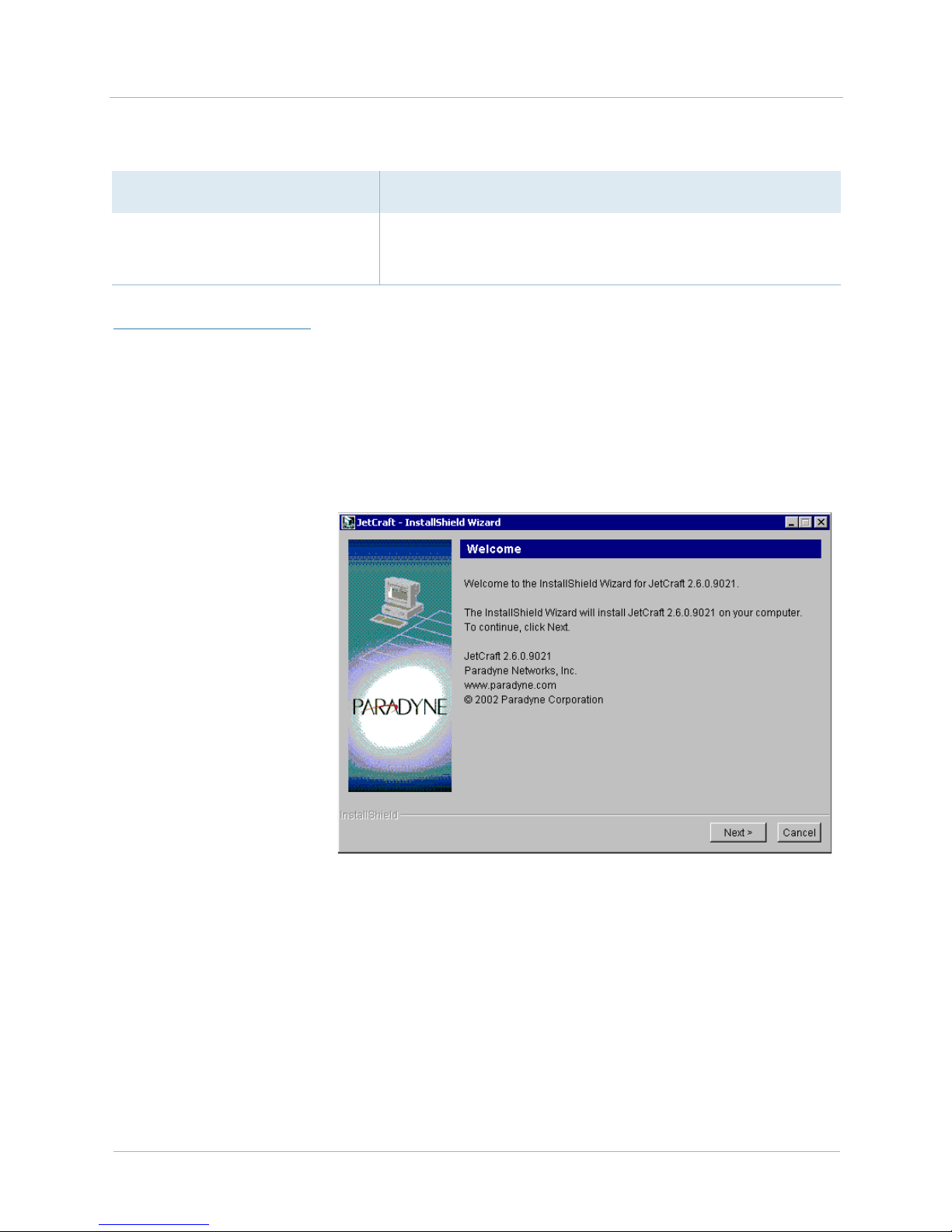
To install the JetCraft software:
A screen appears, indicating the file extraction status. Then the
Welcome screen appears (Figure 2–1).
2-2 June 2005
Figure 2–1. Welcome Screen
Page 23
1000-A2-GB22-10 2. JetCraft Installation
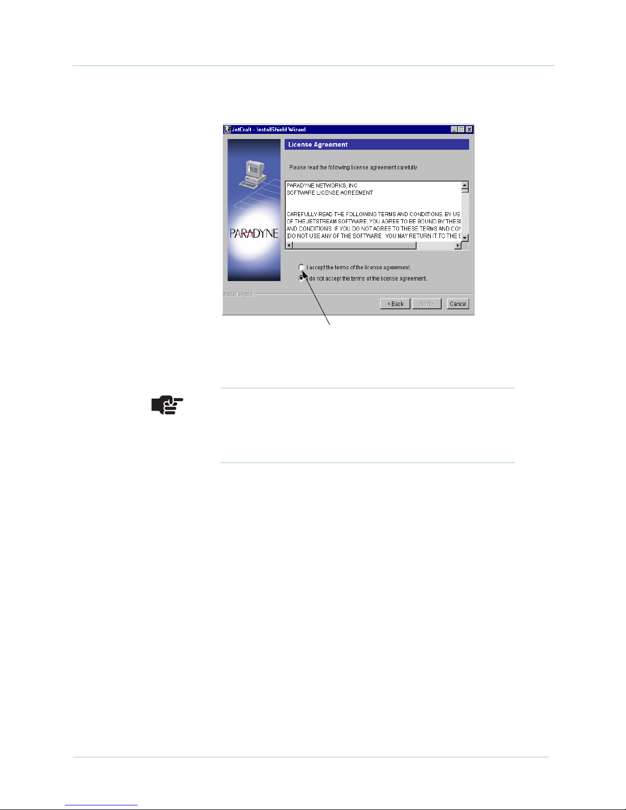
Step 2 Click Next. The License Agreement screen appears (Figure 2–2).
Click here to continue
Figure 2–2. Software Agreement License Screen
Note
At any time during this installation, you can click the
Back button to review or correct the previous settings,
then proceed from that point forward.
June 2005 2-3
Page 24
2. JetCraft Installation 1000-A2-GB22-10
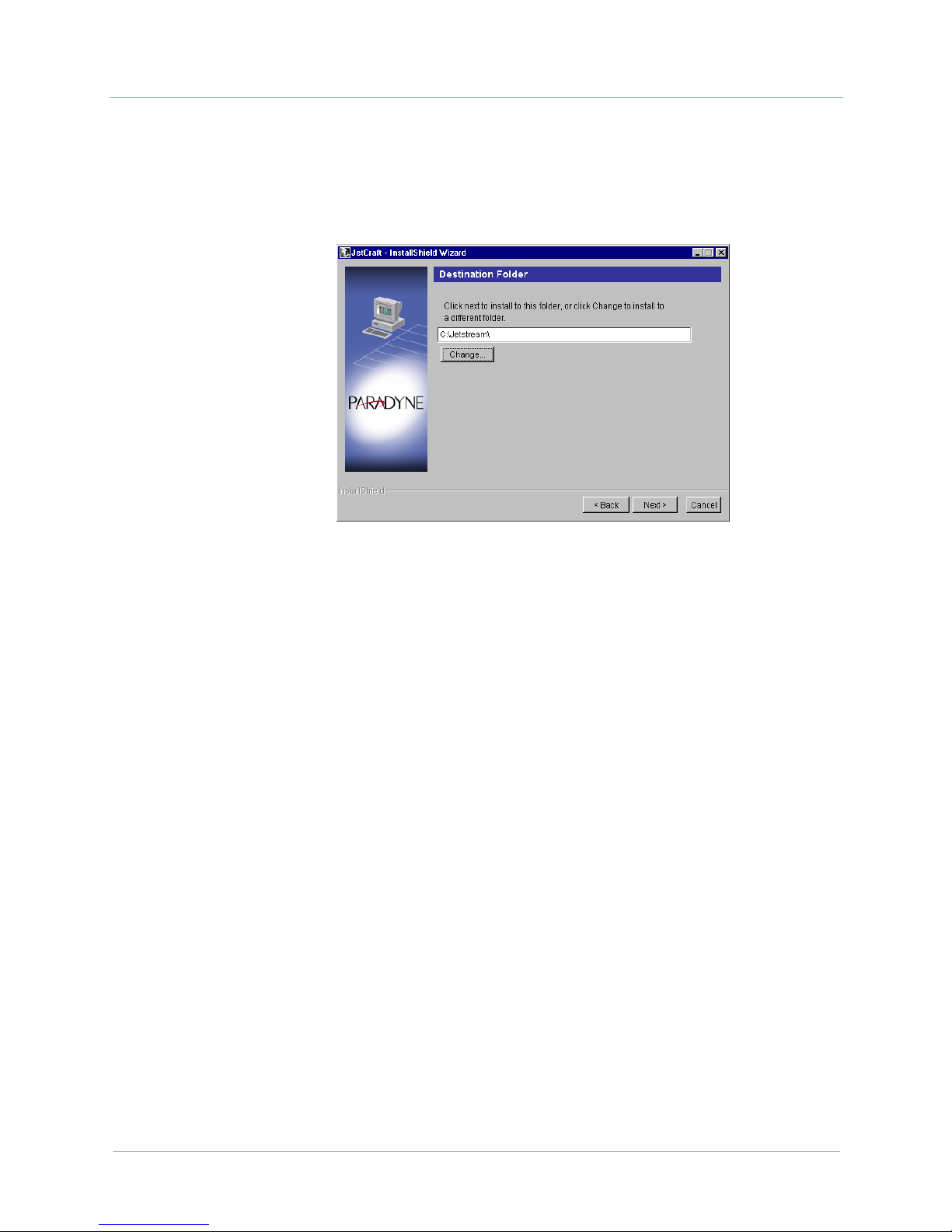
Step 3 Click to select the accept the terms of the license
agreement checkbox, then click Next. The Destination Folder
screen appears (Figure 2–3).
Figure 2–3. Destination Folder Screen
Step 4 Click Next to accept the default path: C:\Jetstream\.
– Or –
Type the directory path in the Destination folder field or
click Change to navigate to where JetCraft will be installed. Then
click Next.
If a folder for JetCraft does not exist, a dialog box appears, asking if
you want to create one. Click Yes.
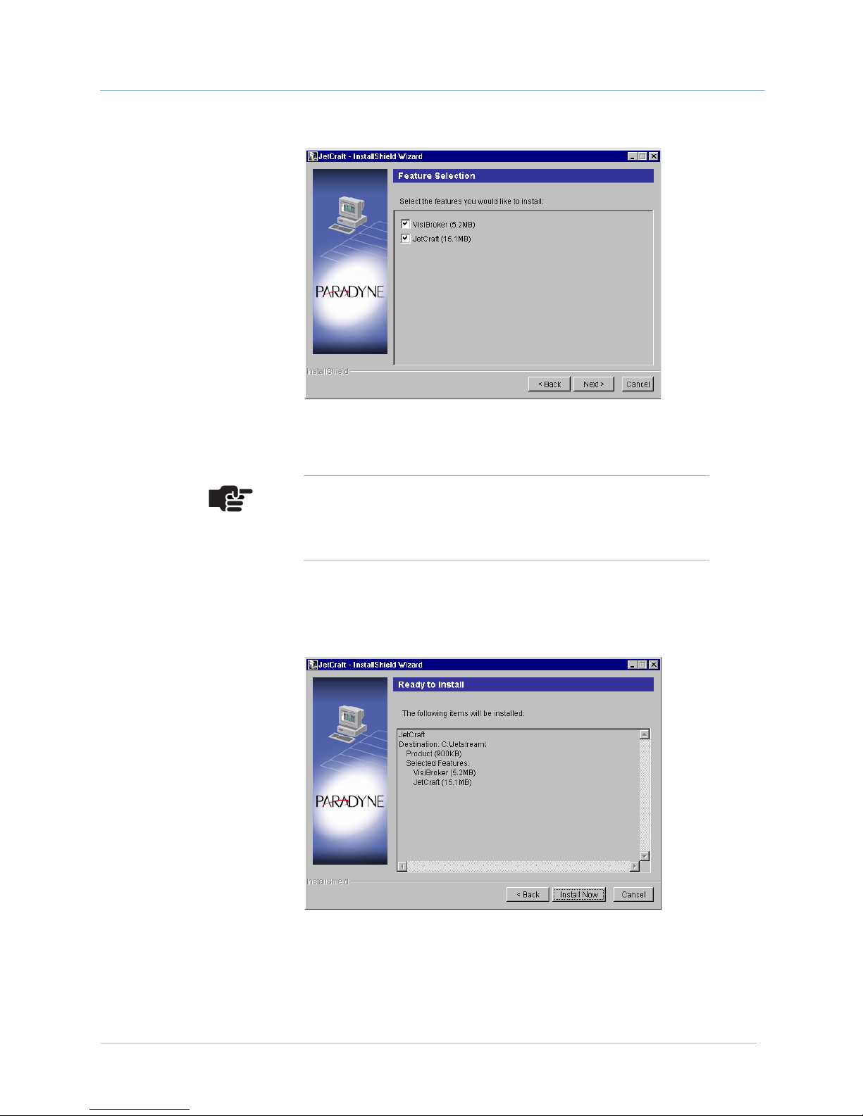
The Feature Selection screen appears, listing the installed features
and their file sizes (Figure 2–4).
2-4 June 2005
Page 25
1000-A2-GB22-10 2. JetCraft Installation
Figure 2–4. Feature Selection Screen
Note
Make sure that both the Visibroker and JetCraft
checkboxes are selected.
Step 5 Click Next. The Ready to Install screen appears, listing the
features to be installed (Figure 2–5).
June 2005 2-5
Figure 2–5. Ready to Install Screen
Page 26
2. JetCraft Installation 1000-A2-GB22-10
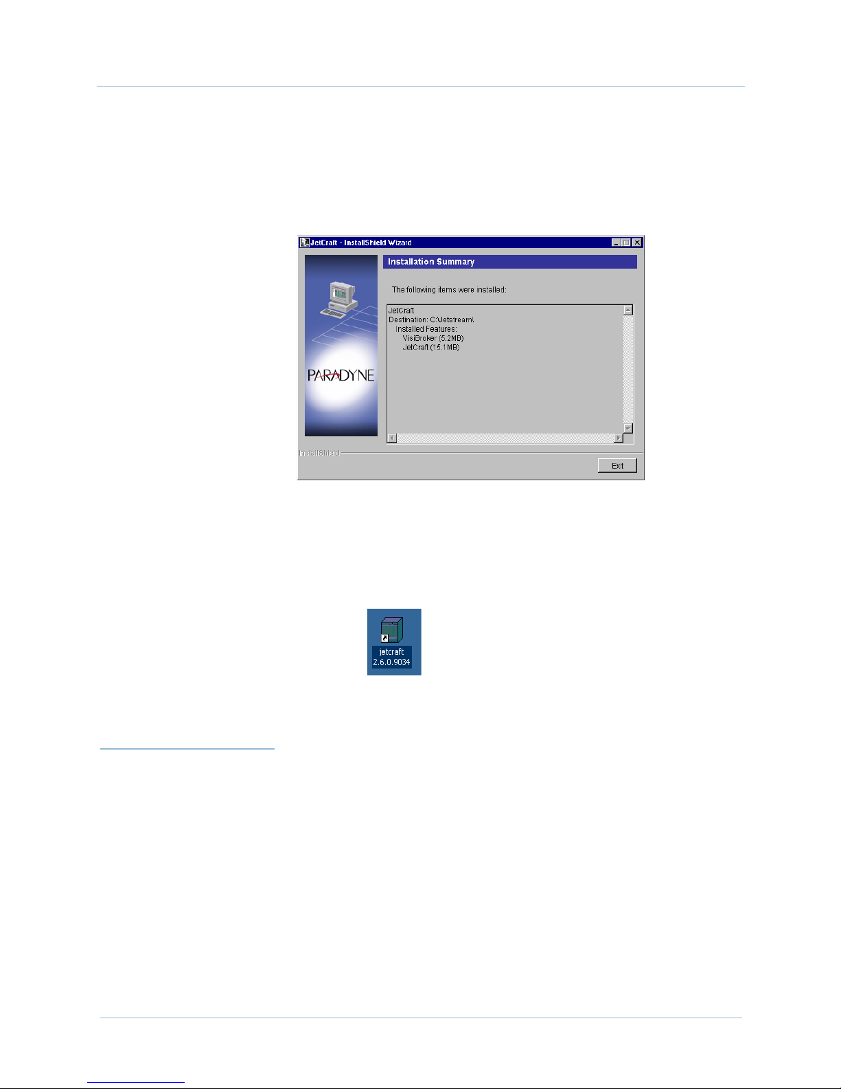
Step 6 Click Install Now. A screen appears, showing the file extraction
progress. After the files are extracted, the Installation Summary
screen appears, listing the installed applications and their file sizes
(Figure 2–6).
Starting
JetCraft
Figure 2–6. Installation Summary Screen
Step 7 Click Exit. The JetCraft icon (Figure 2–7) appears on your
desktop.
Figure 2–7. JetCraft Icon
JetCraft Release 2.6 is not backward compatible. If you log in to a
CPX-1000 running an earlier version, an error message appears,
indicating the version of the CPX-1000 is unsupported.
Once connected, JetCraft pings the CPX-1000 on a repeating
interval and notifies you when the connection is lost
(Re-connecting to JetCraft on page 2-9).
The CPX-1000 is shipped with the following defaults set:
2-6 June 2005
IP address: 10.0.10.100
subnet mask: 255.255.255.0
Page 27
1000-A2-GB22-10 2. JetCraft Installation
Note
Ensure that the craft terminal (PC) and CPX-1000 are on
the same subnet.
To start the JetCraft application:
Step 1 Change the IP address of the craft terminal to match that of
CPX-1000 (Network Neighborhood > TCP/IP tab), but increase the
last digit by one bit. For example, if the IP address of the CPX-1000
is 10.153.145.128, then enter 10.153.145.128.
Step 2 Change the subnet mask of the craft terminal to match that of
CPX-1000.
Step 3 Reboot and restart the craft terminal.
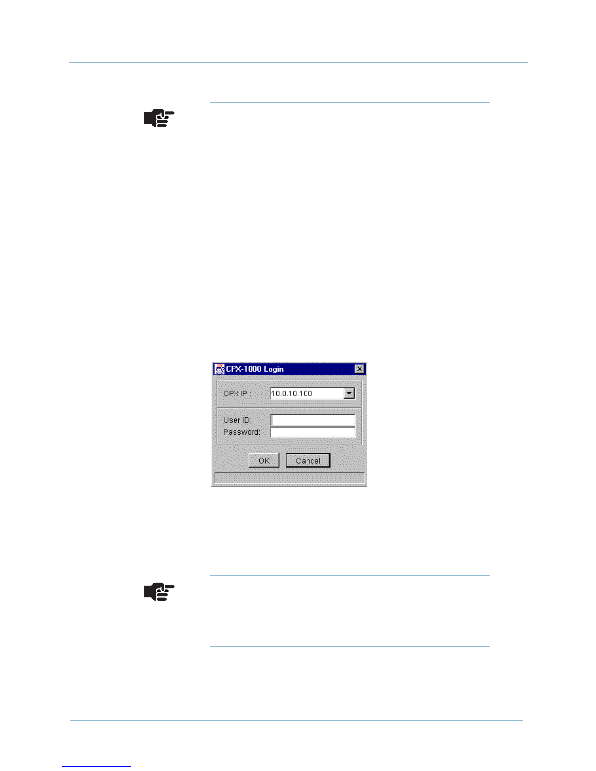
Step 4 Double-click the JetCraft icon on your desktop. The Login dialog
box appears, displaying the default IP address (Figure 2–8).
Step 5 Type the IP address of the CPX-1000 to which you are logging in
Step 6 Typ e cpxuser (default user ID) in the User Id field.
Step 7 Typ e cpxuser (default password) in the Password field.
June 2005 2-7
Figure 2–8. JetCraft Login Dialog Box
the CPX IP field.
Note
Once the IP address is entered, you don’t have to type it
again until you change the CPX-1000 IP address. You
can use the drop-down list to select the IP addresses.
Page 28
2. JetCraft Installation 1000-A2-GB22-10
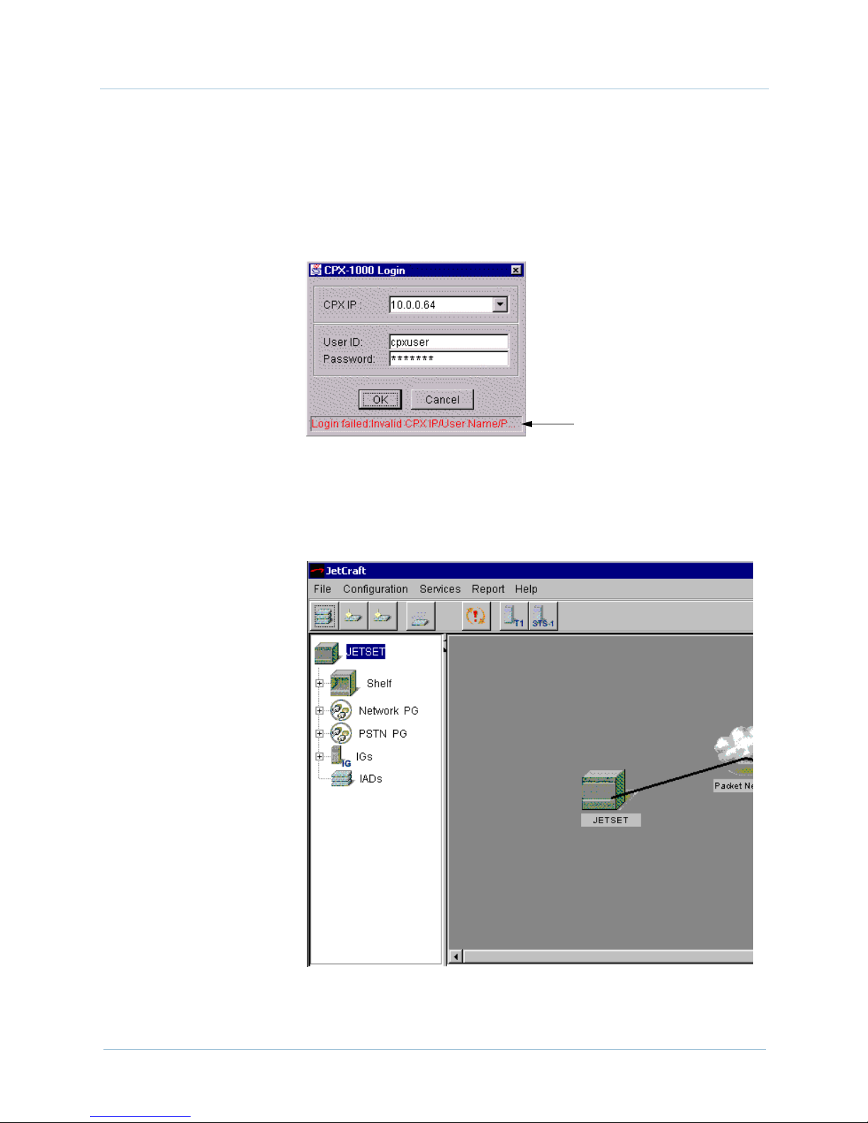
Step 8 Click OK.
If the login fails, a message appears, describing the failure as
shown in Figure 2–9. Click Cancel to exit the login dialog
box. Resolve the login problems, then repeat Step 1 to log in
again.
Login Failure message
Figure 2–9. Login Fail
When the login is successful, the JetCraft Main screen
similar to Figure 2–10 appears.
2-8 June 2005
Figure 2–10. JetCraft Main Screen
Page 29
1000-A2-GB22-10 2. JetCraft Installation
Re-connecting
to JetCraft
Where to Go
Next
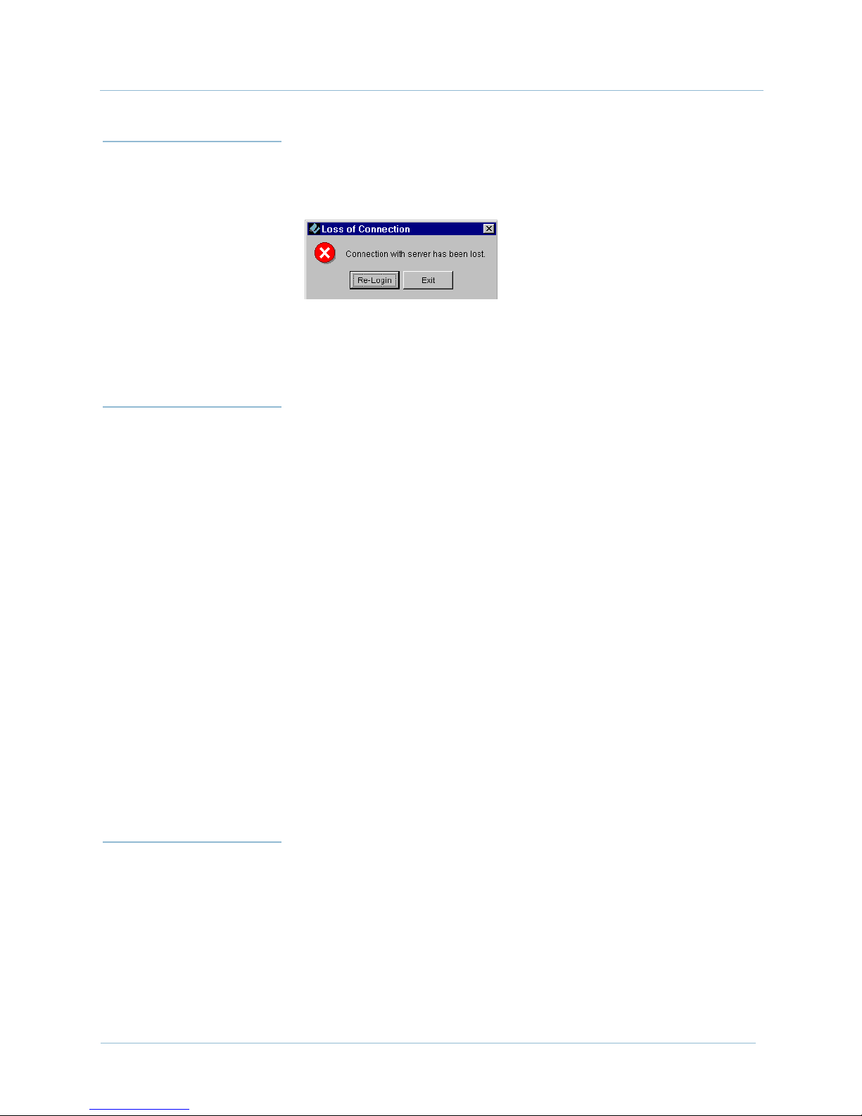
JetCraft automatically times out after a period of inactivity. When
the connection is lost, the following dialog box appears:
Click Re-login. Then type your user ID and password in their
respective fields when the JetCraft Login window reappears.
You can learn about working with the JetCraft Main window
(Chapter 3, JetCraft Basic Operations), or see an overview of all the
menu options on the JetCraft Main window (Appendix A, JetCraft
Menu Map).
You can also use the JetCraft Main screen to configure the
CPX-1000 shelf in the following order:
Configuring CPX-1000 (see Chapter 5, CPX-1000
Configuration) or creating user access (see Chapter 4,
Administration and User Management)
Removing
JetCraft
Step 1 Click the Start button > Settings > Control Panel.
Step 2 Double-click Add/Remove Programs. The Add/Remove
Provisioning Protection Groups (Chapter 6, Protection
Group Provisioning)
Provisioning Interface Groups (Chapter 7, Interface Groups)
Provisioning IAD Profiles and ISDN Port Templates
(Chapter 9, IAD Profiles and IADs Provisioning)
Provisioning IADs (Chapter 10, Alarms, Events, and
Statistics)
To remove an earlier version of JetCraft:
Programs Properties screen appears.
June 2005 2-9
Page 30
2. JetCraft Installation 1000-A2-GB22-10
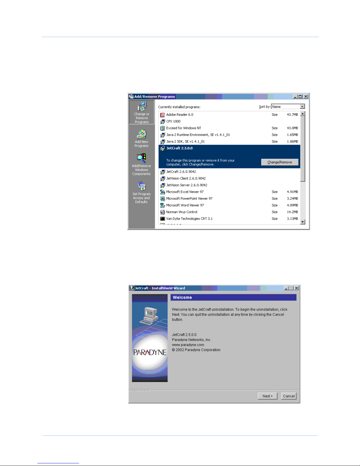
Step 3 Select the JetCraft applications files, click Add/Remove as shown
in Figure 2–11. A dialog box appears, asking if you want to delete
the selected item.
Figure 2–11. Add/Remove Programs Properties Screen
Step 4 Click Yes. The Uninstallation Welcome screen appears
(Figure 2–12).
2-10 June 2005
Figure 2–12. Uninstallation Welcome Screen
Page 31

1000-A2-GB22-10 2. JetCraft Installation
Step 5 Click Next. The Feature Selection screen appears (Figure 2–13).
Figure 2–13. Feature Selection Screen
Step 6 Select the items you want to delete, then click Next. The Ready to
Uninstall screen appears, listing the items to be deleted
(Figure 2–14).
Figure 2–14. Ready to Uninstall Screen
June 2005 2-11
Page 32

2. JetCraft Installation 1000-A2-GB22-10
Step 7 Click Uninstall Now. The Uninstallation Summary screen
appears (Figure 2–15) after the selected items are deleted.
Figure 2–15. Uninstallation Summary Screen
Step 8 Click Exit. You are returned to the desktop.
Step 9 Close the Add/Remove Programs Properties screen.
2-12 June 2005
Page 33

C H A P T E R
3
JetCraft Basic Operations
This chapter describes the JetCraft Main screen and different views
from which it displays and menus. This chapter includes the
following topics:
The JetCraft Main screen (page 3-1)
The JetCraft menus (page 3-7)
The JetCraft
Main Screen
The JetCraft Main screen is an iconic representation of the
CPX-1000 components it manages and the network entities with
which it interfaces. The Main screen is divided into six sections
(Figure 3–1):
Menu bar
Toolbar icons
Tree View
Map View (changes to Shelf View when the Shelf icon is
selected)
Alarm window
Status bar
You can access commands from the menu bar, toolbar icons, and
by right-clicking objects in the Tree and Map views. For a complete
listing of options available for each menu and icons, refer to
Appendix A, JetCraft Menu Map.
June 2005 3-1
Page 34

3. JetCraft Basic Operations 1000-A2-GB22-10
Figure 3–1. JetCraft Main Screen
Menu Bar To use the JetCraft menus to perform an operation, make sure
that you have access to this operation and that you have selected
an appropriate CPX-1000 managed object for the operation. If
your access to the operation is restricted, that menu selection is
grayed out.
Toobar Icons There are six icons on the toolbar (Figure 3–2). You can click an
icon on the toolbar to open the menu selections (except the Alarm
Summary icon).
Click here to create an IAD
Click here to perform IAD
management functions
Click here to create an IAD Profile
Figure 3–2. Toolbar Icons
Click here to create T1 IGs
Click here to create STS-1 IGs
Click here to update alarm summary
3-2 June 2005
Page 35

1000-A2-GB22-10 3. JetCraft Basic Operations
Tree View The Tree View (Figure 3–3) provides a hierarchal view of the
CPX-1000 cards. A plus sign (+) next to the card name indicates
that there are ports assigned to that card. The name of the card
includes the slot number and the name and number of the port. For
example, the card labeled “03-TDM-12T1” indicates that slot 3
contains a TDM T1 card.
To expand and view the structure of the CPX-1000 cards, either
double-click the Shelf icon on the Tree View or click the plus (+)
key next to that icon. Click the minus (–) key to collapse the list.
You can use the Tree View to find specific shelf or alarm
information. Right-click an element icon and choose to view
information about that element.
CPX-1000
Shelf
Card
Por t
Network Protection Group
PSTN Protection Group
June 2005 3-3
Interface Group
IAD
Figure 3–3. Tree View
Page 36

3. JetCraft Basic Operations 1000-A2-GB22-10
Map View Use the Map View (Figure 3–4) to select and view configuration,
performance, and alarm information about the CPX-1000 and
IADs. Right-click an element and choose configuration or report
information.
The Map View shows all Local Digital Switch (LDS, up to four).
You can use the Refresh CPX feature to update the Map View as
the LDS are added or deleted.
Figure 3–4. Map View
Shelf View Clicking the Shelf icon in the Tree View changes the Map View to
Shelf View, displaying the cards installed on your CPX-1000. Use
the Shelf View (Figure 3–5) to select and view configuration,
performance, and alarm information about the CPX-1000 cards.
Right-click a card and choose card configuration or report
information. When Shelf View appears, resize the window to view
the card names at the bottom of the window.
The color shown indicates the states of the cards: green for active
and blue for standby. When in transitional mode (e.g., during
switchover), the card is shown in “wheat” color. Ta bl e 3– 1
describes the types of cards that are currently available and lists
their slots assignment.
For a description of individual cards, refer to CPX-1000 Voice
Services Platform Installation and Operation.
3-4 June 2005
Page 37

1000-A2-GB22-10 3. JetCraft Basic Operations
Figure 3–5. Shelf View
Table 3–1. CPX-1000 Cards
Card Type Abbreviation Valid Slot Assignment
Call Processing, primary (A) or
secondary (B)
Hot Swap Controller (bridge),
primary (A) or secondary (B)
CP-A
CP-B
HSC-A
HSC-B
7
9
10
8
Management Processing MP 6
ATM-OC3 OC3 Slots 1–5 and 11–16
ATM-DS3 DS3 Slots 1–5 and 11–16
TDM-T1 TDM-12 Slots 1–5 and 11–16
Synchronous transport signal-1 STS-1 Slots 1–5 and 11–16
The Alarm
Window
Alarms appear in the current alarm summary window as shown in
Figure 3–6. Update the current alarm summary by clicking on
the toolbar.
June 2005 3-5
Page 38

3. JetCraft Basic Operations 1000-A2-GB22-10
You can sort and view alarm information by clicking any one of the
Alarm window column headings. Click another column heading
to change the sort order again.
Figure 3–6. Alarm Window
Alarmed elements appear in the Tree View and Map View in a
color relating to their alarm severity (Tab le 3 –2 ). Alarms are also
indicated by a large X on the affected object in the Tree View. The
color of the X indicates the severity of the alarm (Chapter 10,
Alarms, Events, and Statistics).
Table 3–2. Alarm Severity by Color
Alarm Severity Color
Critical red
Major orange
Minor yellow
Indeterminate blue
Unknown cyan
3-6 June 2005
Page 39

1000-A2-GB22-10 3. JetCraft Basic Operations
The Status Bar The status bar displays alarm events and messages (Figure 3–7).
Two colors indicate the type of message: blue for status and red for
error.
Refer to Chapter 10, Alarms, Events, and Statistics for message
definitions.
Displayed message
Figure 3–7. Status Bar
JetCraft Menus Four menus provide JetCraft operations:
File menu
Configuration menu
Services menu
Report menu
The Help menu provides a quick look-up of JetCraft procedures. It
also provides an easy and convenient way to view information
about JetCraft.
The File Menu Use the File menu to:
refresh the CPX-1000 display after change
exit JetCraft
CPX-1000 IP
User ID
June 2005 3-7
Page 40

3. JetCraft Basic Operations 1000-A2-GB22-10
The
Configuration
Menu
Operations displayed in the Configuration menu and icons
selected in the Tree View are mutually inclusive; that is, an icon
needs to be selected before the operation becomes available.
Use the Configuration menu to:
configure CPX cards and ports (Chapter 5, CPX-1000
Configuration)
perform CP, MP, and line cards switchover (Chapter 11,
Maintenance and Services)
create and manage Interface Group (Chapter 7, Interface
Groups)
poll DS1 error statistics (Chapter 10, Alarms, Events, and
Statistics)
perform EOC/TMC switchover (Chapter 7, Interface
Groups)
configure PPS settings (Chapter 7, Interface Groups)
swap between the primary and secondary members of the
Protection Group (Chapter 6, Protection Group
Provisioning)
perform a STS-1 path trace (Chapter 11, Maintenance and
Services)
create and manage IAD profiles (Chapter 9, IAD Profiles
and IADs Provisioning)
create and manage IADs (Chapter 9, IAD Profiles and IADs
Provisioning)
launch Integrated Monitor (Chapter 12, Integrated
Monitoring)
synchronize BITS clock (Chapter 5, CPX-1000
Configuration)
configure LBO values (Chapter 5, CPX-1000 Configuration)
poll CP performance statistics (Chapter 10, Alarms, Events,
and Statistics)
3-8 June 2005
Page 41

1000-A2-GB22-10 3. JetCraft Basic Operations
The Services
Menu
Use the Services menu to:
back up and restore the CPX-1000 configuration
(Chapter 11, Maintenance and Services)
set the alarm polling interval (Chapter 10, Alarms, Events,
and Statistics)
set up the VCI value (Chapter 5, CPX-1000 Configuration)
configure the CPX IP address (Chapter 5, CPX-1000
Configuration)
change the CPX time (Chapter 11, Maintenance and
Services)
reboot the CPX-1000 (Chapter 11, Maintenance and
Services)
create a CPX user profile (Chapter 4, Administration and
User Management)
change password (Chapter 4, Administration and User
Management)
The Report Menu Use the Report menu to generate:
error graph statistics (Chapter 10, Alarms, Events, and
Statistics)
performance graph statistics (Chapter 10, Alarms, Events,
and Statistics)
The Help Menu Use the Help menu to:
launch the JetCraft Help
view information about JetCraft
June 2005 3-9
Page 42

3. JetCraft Basic Operations 1000-A2-GB22-10
3-10 June 2005
Page 43

C H A P T E R
4
Administration and User
Management
This chapter provides instructions for provisioning users. These
tasks include:
Understanding user access control (page 4-1)
Changing user passwords (page 4-2)
Creating CPX users (page 4-3)
Although you can install JetCraft anytime, typically, you install the
CPX-1000 and then the JetCraft software. After installation, use
JetCraft to configure users and assign their access privileges. These
users can access the CPX-1000 and create Interface Groups and
IADs.
Understanding
User Access
Control
When you first start JetCraft, log in using the default user ID
(cpxuser) and password (cpxuser). The default user ID belongs to an
authorized user group that has access to all CPX operations. To
limit CPX-1000 access, we recommend changing the default
password as soon as possible.
Each user group has a specific level of access and privilege, and
users belonging to a specific group can only perform operations
that are assigned to that group. Each user is given a password
when the user group is created. Tabl e 4– 1 lists and defines the user
access levels and their privileges.
June 2005 4-1
Page 44

4. Administration and User Management 1000-A2-GB22-10
Table 4–1. User Access Level Summary
Access Level Privilege
Admin This group has full access to all features of JetCraft, including changing other
user’s passwords. They can create, modify, and delete all users, and can
change JetCraft configuration.
Operations This group can access JetCraft configuration but cannot create, modify, or
delete all users. They can change their own password but not others.
Reports This group can only view reports and statistics but cannot make or save any
changes.
Changing a
User Password
Step 1 Select Change CPX Password from the Services menu. The
To change your own password or to change another user’s
password (if you have Admin privileges):
Change Password window appears (Figure 4–1).
Figure 4–1. Change Password Window
Step 2 Type the old and new password.
Step 3 Type the new password again.
Step 4 Click OK to change the password.
4-2 June 2005
Page 45

1000-A2-GB22-10 4. Administration and User Management
Creating CPX
Users
Step 1 Select Create CPX User from the Services menu. The Create
To create a CPX user:
User window appears (Figure 4–2).
Figure 4–2. Create User Window
Step 2 Enter the following information (up to 32 alphanumeric characters
including spaces and punctuation) in their respective fields:
ID—user’s login ID
Name—user’s name
Password—user’s password
Retype—the user’s password
Expiration Date—default is set to 10 years from the date
when this user is created (required Admin privilege to
modify)
Group—select Admin, Operations, or Reports from the
drop-down list
Note
The Address, Contact, and Comment tabs are optional.
June 2005 4-3
Page 46

4. Administration and User Management 1000-A2-GB22-10
Step 3 Click Address. The Address page appears (Figure 4–3).
Figure 4–3. Create User Window—Address Tab
Step 4 Enter the address in their respective fields (up to 32 alphanumeric
characters including spaces and punctuation).
Step 5 Select Contact. The Contact page appears (Figure 4–4).
Figure 4–4. Create User Window—Contact Tab
4-4 June 2005
Page 47

1000-A2-GB22-10 4. Administration and User Management
Step 6 Enter the phone number, pager, and Email in their respective fields
(up to 32 alphanumeric characters including spaces and
punctuation).
Step 7 Select Comments. The Comment page appears (Figure 4–5).
Figure 4–5. Create User Window—Comment Tab
Step 8 Click anywhere in the Comment area and enter comments about
the user.
Step 9 Click OK to create the CPX user.
June 2005 4-5
Page 48

4. Administration and User Management 1000-A2-GB22-10
Modifying CPX
Users
Step 1 Select CPX User Administration from the Services menu. The
To modify CPX user information (an Administrative privilege is
required):
Update User Information window appears (Figure 4–6).
Figure 4–6. Update User Informations Window
In addition to modifying user information, you can also perform
the following tasks:
add a new user (page 4-3)
delete an existing user (page 4-8)
Step 2 Select the user whose information you want to modify.
4-6 June 2005
Page 49

1000-A2-GB22-10 4. Administration and User Management
Step 3 Click Modify. The Modify User window appears (Figure 4–7).
Figure 4–7. Modify User Window
Step 4 Modify the fields (if necessary) in any of the Modify User tabs
(Creating CPX Users on page 4-3.)
Note
The ID and Expiration Date fields cannot be modified.
Step 5 Click OK to modify the CPX user.
June 2005 4-7
Page 50

4. Administration and User Management 1000-A2-GB22-10
Deleting CPX
User
Step 1 Select the user you want to delete from the Update User
Step 2 Click Delete. A message appears, asking if you want to delete the
Step 3 Click Yes. The user is deleted.
Reviewing
CPX Users
To delete a CPX user (an Administrative privilege is required):
Information window (Figure 4–6 on page 4-6).
selected user.
To review the newly created or existing CPX users, select CPX
User Administration from the Services menu. The Update
User Information window (Figure 4–6 on page 4-6) displays the
CPX users information.
4-8 June 2005
Page 51

C H A P T E R
5
CPX-1000 Configuration
This chapter provides instruction for configuring the CPX-1000. It
includes the following tasks:
Modifying IP configuration (page 5-5)
Configuring global VCI settings (page 5-6)
Setting CDV value (page 5-8)
Setting LBO value (page 5-9)
Configuring the STS-1 card (page 5-10)
Setting the clock source (page 5-11)
Refreshing the CPX after modifications (page 5-13)
The CPX-1000 is shipped with the following default and a
standard configuration profile that you use JetCraft to customize
for a specific subscriber.
IP address: 10.0.10.100
subnet mask: 255.255.255.0
If the CPX-1000 is configured, JetCraft automatically places the
cards in service (i.e., unlocked state) when you log in.
If the CPX-1000 has not been configured, you need to:
ensure the CPX-1000 equipment is installed
customize or modify the CPX-1000 profile
configure the CPX-1000 for telephone service
monitor equipment initialization for event messages and
alarms
June 2005 5-1
Page 52

5. CPX-1000 Configuration 1000-A2-GB22-10
CPX-1000
Configuration
Profile
Table 5–1. CPX-1000 Configurable Parameters
CPX Parameter Description
ID An identifier associated with the CPX-1000, consists of 4–63
Name A name for the CPX-1000 that consists of up to 63 alphanumeric
The CPX-1000 is preprovisioned with a standard configuration
profile.
Since most of the CPX-1000 configuration parameters cannot be
changed after Interface Groups and IADs are provisioned, modify
the CPX-1000 configuration at startup.
Table 5–1 lists the configuration parameters needed for configuring
the CPX-1000 in JetCraft.
alphanumeric characters (e.g., JET1). No spaces, underlined
characters, etc. allowed.
characters (e.g., JETSET). No spaces, underlined characters, etc.
allowed.
Use this name for differentiating CPX-1000s, error reporting, and
when creating an IAD.
IP Address The 32-bit Internet Protocol address assigned to the CPX-1000.
Default Gateway The IP address that allows the CPX-1000 to be addressed over a
LAN or WAN.
Subnet Mask The 32-bit identifier that allows the IP address of the CPX-1000 to
be used with multiple connections.
Administrative State JetCraft administrative service-affecting state of CP cards and
ports. Options are:
Unlocked: Capable of service
Locked: Restricted from service (card is in the shelf, but
JetCraft or JetVision administrators restricted it from
service)
Operational State The operational state of the CPX-1000 cards and ports. Options
are:
Enabled
Disabled
5-2 June 2005
Page 53

1000-A2-GB22-10 5. CPX-1000 Configuration
Modifying
CPX-1000
Parameters
Step 1 Select in the Tree View.
Step 2 Select Configure from the Configuration menu.
To modify the CPX-1000 parameters:
– Or –
Right-click in the Map View and select Configure.
The CPX Configuration window appears (Figure 5–1).
Step 3 Enter your modification(s) between 4 to 63 alphanumeric
June 2005 5-3
Figure 5–1. CPX Configuration Window
Note
You can modify the Name and the ID fields; other fields
are read only.
characters (no spaces, underlines, or slashes).
the ID field
the Name field (the identifier used in the Map View and
identifies which IADs belong to the CPX-1000)
Page 54

5. CPX-1000 Configuration 1000-A2-GB22-10
Step 4 Select Status. The Status tab window (Figure 5–2) displays the
current, read-only operational status of the CPX-1000.
Step 5 Click OK to modify the CPX-1000 parameters.
Reviewing
CPX-1000
Parameters
Step 1 Select in the Tree View.
Step 2 Select Configure from the Configuration menu.
Figure 5–2. CPX Configuration Window—Status Tab
To review the CPX-1000 parameters:
– Or –
Right-click in the Map View and select Configure.
The CPX Configuration window (Figure 5–1 on page 5-3) displays
the name and the identifier of the CPX-1000 and other read-only
information, such as default gateway, IP address, serial number,
and subnet mask.
5-4 June 2005
Page 55

1000-A2-GB22-10 5. CPX-1000 Configuration
Modifying IP
Configuration
Step 1 Select the MP card from the Tree View or Shelf View.
Step 2 Select IP Configuration from the Services menu. The CPX IP
To modify IP configuration, you need the following information:
IP address
Subnet mask
Default Gateway
Configuration window appears (Figure 5–3).
Figure 5–3. CPX IP Configuration Window
Note
You can modify the IP address only when the MP card is
selected.
Step 3 Type the new IP address, subnet mask, and default gateway in the
respective fields.
June 2005 5-5
Page 56

5. CPX-1000 Configuration 1000-A2-GB22-10
Step 4 Click OK. A dialog box appears, asking you if you want to reboot
the CPX-1000.
Warning
Rebooting the MP card interrupts service.
Step 5 Click Yes.
When the CPX-1000 reboots, your changes are accepted.
Configuring
Global VCI
Settings
If you click No, your changes will not take effect.
Note
After you reboot the CPX-1000, we recommend that you
exit and re-login to JetCraft.
You can change the VCI value only when there are no IADs
provisioned to the CPX-1000. The default value is 1024.
Warning
Changing the VCI value requires rebooting the CPX-1000.
Rebooting the CPX-1000 drops all calls.
5-6 June 2005
Page 57

1000-A2-GB22-10 5. CPX-1000 Configuration
To set the VCI value:
Step 1 Select Configure Global System from the Services menu. The
Global System Setting window appears (Figure 5–4).
Figure 5–4. Global System Setting Window
Step 2 Type the VCI value or select one from the drop-down list. Your
options are 64, 128, 256, 512, 1024.
Note
This value determines the number of VCIs allowed per
VPI.
Step 3 Click OK. A dialog box appears, informing you that a reboot is
required and asking if you want to continue with the update.
Step 4 Click OK. When the reboot process completes, the following dialog
box appears.
Step 5 Click Re-login. Then type your user ID and password in their
respective fields when the JetCraft Login window reappears.
June 2005 5-7
Page 58

5. CPX-1000 Configuration 1000-A2-GB22-10
Setting CDV
Value
Step 1 Locate the CPX-1000 by clicking the group icon from the Tree View
Step 2 Click a CPX-1000 and expand the tree.
Step 3 Click the CPX-1000 icon from the Tree View.
Step 4 Select Configure from the Configuration menu. The CPX
Cell Delay Variation (CDV) is a QoS parameter that measures the
time needed for each cell to travel over the Virtual Circuit (VC).
The value expressed is in the microsecond (ms). The higher the
CDV value, the less the calls allowed.
To set the CDV value:
where the CPX-1000 resides.
Configuration window appears (Figure 5–5).
Step 5 Type the values between 1 – 60 in both the ATM and Frame Relay
Step 6 Click OK.
5-8 June 2005
Figure 5–5. CPX Configuration Window
fields (default for ATM is 8 ms and frame relay is 28 ms).
Page 59

1000-A2-GB22-10 5. CPX-1000 Configuration
Setting LBO
Value
Step 1 Locate the CPX-1000 by clicking the group icon from the Tree View
Step 2 Click a CPX-1000 and expand the tree.
Step 3 Click the CPX-1000 icon from the Tree View.
Step 4 Select LBO Value from the Configuration menu.
Line Build Out (LBO) is used to offset the output attenuation.
To set the LBO value:
where the CPX-1000 resides.
The following dialog box appears.
Step 5 Select the linear measurement (feet) from the drop-down lists.
Ranges for T1 LBO are:
— 0–133
— 133–266 (default)
— 266–366
— 399–533
— 533–655
Options for STS1 LBO are Above 100 ft. (default) or Below
100 ft.
Step 6 Click OK.
June 2005 5-9
Page 60

5. CPX-1000 Configuration 1000-A2-GB22-10
Configuring
STS-1 Card
Step 1 Click the Shelf icon associated with the CPX-1000 and expand the
Step 2 Expand the STS-1 card on the Tree View, and select BITs.
Step 3 Select Configure from the Configuration menu. The Port
To change the frame format and line encoding on the STS-1 card:
tree by clicking the + sign.
Configuration window appears (Figure 5–6).
Figure 5–6. STS1 BITS Port Configuration
Step 4 Click Status. The Status tab appears (Figure 5–7).
Figure 5–7. STS1 BITS Port Configuration—Status Tab
5-10 June 2005
Page 61

1000-A2-GB22-10 5. CPX-1000 Configuration
Step 5 Select the frame format options (SF or ESF) from its drop-down list.
Step 6 Select the line encoding options (AMI or B8ZS) from its drop-down
list.
Setting Clock
Source
Step 1 Select in the Tree View, then select Clock Synch from the
Clock source comes from BITS (STS-1 cards) and Interface Groups.
There are 13 possible priorities. When present, priorities 1 through
4 are used for STS-1 cards and 5 through 12 for interface groups.
Priority 13 is reserved for system clock and is not userconfigurable.
When the revertive behavior is selected, it takes place across all
priorities. For example, priorities 1 and 2 lose the clock, and
priority 3 takes over and is actively driving the bus. When priority
1 regains its clock, then priority 1 will then take control of driving
the bus.
To assign priority of CPX clock source:
Configuration menu.
– Or –
Right-click in the Tree View and select Clock Synch.
The Clock Synch window similar to Figure 5–8 appears.
June 2005 5-11
Figure 5–8. Clock Synch Window
Page 62

5. CPX-1000 Configuration 1000-A2-GB22-10
Notes
The Priority and Status fields are read only.
The number of clock source available is based on the
number of STS-1 cards and Interface Groups you have
configured on your CPX-1000.
Step 2 Select a row in which you want to remove a clock source.
Step 3 Remove the old clock source by double-clicking the Clock Source
field and selecting the blank line. The clock source is moved to the
Unassigned Clocks panel (Figure 5–9).
5-12 June 2005
Figure 5–9. Clock Synch Window with Clocks
Unassigned
Page 63

1000-A2-GB22-10 5. CPX-1000 Configuration
Step 4 Select a row in which you want to set a new clock source.
Step 5 Double-click the Clock Source field, and select a new clock source.
The selected clock source is moved from the Unassigned Clocks
panel and is displayed in the Clock Source field (Figure 5–10).
Step 6 Select a revertibility policy (default is Revertive).
Step 7 Click OK.
Refreshing the
CPX-1000
Display
Figure 5–10. Clock Synch Window with Clocks Assigned
To refresh the CPX-1000 display after you’ve made modifications,
select Refresh CPX from the File menu. The CPX-1000 display is
updated with your modifications, and the message
Refreshing...Done appears in the status bar.
June 2005 5-13
Page 64

5. CPX-1000 Configuration 1000-A2-GB22-10
5-14 June 2005
Page 65

C H A P T E R
6
Protection Group
Provisioning
This chapter provides instructions to provision network (ATM)
and PSTN Protection Groups. This chapter includes the following
tasks:
Assigning members to the ATM network Protection Group
(page 6-2)
Assigning members to the PSTN network Protection Group
(page 6-5)
Swapping Protection Group members (page 6-7)
Removing member from the Protection Group (page 6-9)
The network redundancy uses duplicate links between the ATM
network and ATM card (OC-3 or DS-3) whereby you can assign
which ATM interfaces on the CPX-1000 are associated with a
particular Protection Group.
Ta bl e 6– 1 describes the fields in the Protection Group.
Table 6–1. Protection Group Summary
Fields Description
ID Four network and six PSTN protection
groups are assigned by CPX Management
Entity (CME), you cannot add or delete
protection groups.
Primary
Member
Secondary
Member
The active port of the Protection Group is
specified by slot_number/port_number and
indicated by a green background.
The standby port of the Protection Group is
indicated by a blue background. “Not
assigned” indicates that the protection group
has no members.
June 2005 6-1
Page 66

6. Protection Group Provisioning 1000-A2-GB22-10
Note
The gray background indicates that the states (active/
standby) of the card are unknown because the card
corresponding to a member has been removed;
however, the slot/port information continues to display.
Assigning
Network
Protection
Group
Members
Step 1 Click Network PG on the Tree View, the right-hand pane
Before assigning members to the network protection group, make
sure that the CPX-1000 is up with redundant ATM cards (OC-3 or
DS-3).
To assign members to the network Protection Group:
changes to the network Protection Group tabular view
(Figure 6–1).
Right-click these fields and select Configure
Step 2 Select a protection group to which you want to assign member.
6-2 June 2005
Figure 6–1. Network Protection Group Tabular View
Page 67

1000-A2-GB22-10 6. Protection Group Provisioning
Step 3 Select Configure from the Configuration menu.
– Or –
Right-click the highlighted selection and select Configure from
the pop-up menu.
The Configuration for Network PG window appears (Figure 6–2).
Figure 6–2. Configuration for Network PG Window
Step 4 Select a slot and port number for the Primary Member from the
Slot/Port drop-down list. Once a port assignment is selected, all
other fields in the area are automatically populated.
Notes
You cannot assign ports that are already members of
some other Protection Group.
Ensure that you assign the same port type to the same
Protection Group.
June 2005 6-3
Page 68

6. Protection Group Provisioning 1000-A2-GB22-10
Step 5 Select Unlocked from the Admin State drop-down list.
Step 6 Repeat Step 5 for the Secondary Member.
Step 7 Select a cable type.
For OC-3 ports, select Straight.
For DS-3 ports, select either Y-cable or Straight.
Note
The APS selection is enabled only when straight cable is
selected.
Step 8 Click to select the Unidirectional 1 Plus 1 to enable the
ATM switch to automatically switch the active to standby if the
card fails.
Step 9 Click OK. The newly created Protection Groups display in the
tabular view (Figure 6–3).
Figure 6–3. Protection Groups Displayed in Tabular
View
6-4 June 2005
Page 69

1000-A2-GB22-10 6. Protection Group Provisioning
Assigning PSTN
Protection
Group
Members
Step 1 Click PSTN PG on the Tree View, the right-hand pane changes
Before assigning members to the PSTN network Protection Group,
make sure that the CPX-1000 is up with redundant STS-1 cards.
To assign members to the PSTN Protection Group:
to the PSTN Protection Group tabular view (Figure 6–4).
Right-click these fields and
select Configure
Figure 6–4. PSTN Protection Group Tabular View
Step 2 Select a PSTN protection group member that you want to assign.
Step 3 Select Configure from the Configuration menu.
– Or –
Right-click the highlighted selection and select Configure from
the pop-up menu.
The Configuration for PSTN PG window appears (Figure 6–5).
June 2005 6-5
Page 70

6. Protection Group Provisioning 1000-A2-GB22-10
Figure 6–5. Configuration for PSTN PG Window
Step 4 Select a slot and port number for the Primary Member from the
Slot/Port drop-down list. Once a port assignment is selected, all
other fields in the area are automatically populated.
Notes
You cannot assign ports that are already members of
some other Protection Group.
Ensure that you assign the same port type to the same
Protection Group.
Step 5 Select Unlocked from the Admin State drop-down list.
Step 6 Repeat Step 5 for the Secondary Member.
Step 7 Select Y-cable.
Step 8 Click OK. The newly created Protection Group display in the
tabular view (Figure 6–6).
Figure 6–6. Protection Groups Displayed in Tabular
View
6-6 June 2005
Page 71

1000-A2-GB22-10 6. Protection Group Provisioning
Swapping
Protection
Group
Members
Step 1 Place the ATM ports to which an ATM Protection Group will be
Step 2 Click the desired PG icon (Network or PSTN) on the Tree View, the
To swap between the primary and secondary members of the
Protection Group:
switched in the Locked state.
Protection Group Manager window similar to Figure 6–7.
Figure 6–7. Protection Group Manager
Step 3 Select a Protection Group ID to which you want to switch member.
Step 4 Select Configure from the Configuration menu.
– Or –
Right-click the highlighted selection and select Configure.
The Protection Group Manager window similar to Figure 6–8
appears.
June 2005 6-7
Page 72

6. Protection Group Provisioning 1000-A2-GB22-10
Figure 6–8. Configuration for Network PG Window
Note
The APS feature is not applicable for the PSTN PG.
Step 5 Select Locked from the Admin State drop-down list.
Step 6 Click OK to return to the Protection Group Manager window.
Step 7 Select PG Swap from the Configuration menu.
– Or –
Right-click the highlighted selection and select PG Swap from the
pop-up menu.
Step 8 Observe the colors. The Primary Member is now blue and the
Secondary Member green.
6-8 June 2005
Page 73

1000-A2-GB22-10 6. Protection Group Provisioning
Removing
Protection
Group
Members
Step 1 Click the desired PG icon (Network or PSTN) on the Tree View, the
Before removing members from a Protection Group, ensure that
the port assigned to the group member is Locked.
To remove members from a Protection Group:
Protection Group Manager window similar to Figure 6–9 appears.
Figure 6–9. Protection Group Manager
Step 2 Select a Protection Group member that you want to remove.
Step 3 Select Configure from the Configuration menu.
– Or –
Right-click the highlighted selection and select Configure from
the pop-up menu.
The Configuration for Network PG window similar to Figure 6–10
appears.
June 2005 6-9
Page 74

6. Protection Group Provisioning 1000-A2-GB22-10
Figure 6–10. Protection Group Manager Window
Step 4 Select Unassigned from the Slot/Port drop-down list for the
Secondary Member.
Step 5 Select Locked from the Admin State drop-down list.
Step 6 Repeat Step 5 for the Primary Member.
Note
The unassigned list does not appear in the Slot/
Port drop-down list in the Primary Member area
until after you select unassigned for the Secondary
Member. This selection ensures that the primary port
(Primary Member) remains assigned when the
secondary port is unassigned.
Step 7 Click OK.
Step 8 Select Refresh CPX from the File menu to view your changes.
6-10 June 2005
Page 75

C H A P T E R
Interface Groups
This chapter provides instructions to provision the Interface
Groups. These tasks include:
Creating T1 Interface Groups (page 7-2)
Creating STS-1 Interface Groups (page 7-8)
Assigning ports/channels to GR-303 Interface Groups
(page 7-12)
Removing ports/channels from GR-303 Interface Groups
(page 7-16)
Assigning ports/channels to the T1-CAS Interface Group
(page 7-18)
7
Removing ports/channels from the T1-CAS Interface Group
(page 7-21)
Modifying GR-303 Interface Groups (page 7-23)
Deleting GR-303 Interface Groups (page 7-25)
Performing an EOC switchover (page 7-27)
Performing a TMC switchover (page 7-29)
Configuring PPS settings (page 7-31)
JetCraft supports up to eight Interface Groups for each CPX-1000.
Each Interface Group supports up to 28 DS1 lines or 28 channels
from the CPX-1000.
Typically, the Interface Groups are created without a physical
connection. As a result, the Interface Groups are alarmed as they
are created, then cleared when they are connected to the cable.
Ta bl e 7– 1 lists the parameters you will need to configure the
Interface Group.
Note
An empty T1 CAS Interface Group is available by default. The
Interface group ID for T1 CAS is 9. The group cannot be deleted.
June 2005 7-1
Page 76

7. Interface Groups 1000-A2-GB22-10
The Modify operation for T1 CAS consists only of assigning and
unassigning DS1s.
Table 7–1. Interface Group Configuration Parameters Summary
Parameters Description
Name The Interface Group name. The name is used for error reporting and
to identify the interface group and assign subscribers.
LDS The Local Digital Switch. The name of the host switch to which the
interface group connects.
Model The host switch model (e.g., Lucent 5ESS, Siemens EWSD).
Primary DS1 The primary DS1 number used for the primary TMC and EOC
channels.
Secondary DS1 The secondary DS1 number you want to use for the secondary TMC
and EOC channels.
Creating T1
Interface
Groups
Step 1 Click on the Tree View, the right-hand pane changes to the
To create a T1 Interface Group:
Interface Group tabular view (Figure 7–1).
7-2 June 2005
Page 77

1000-A2-GB22-10 7. Interface Groups
Figure 7–1. Interface Group Tabular View
June 2005 7-3
Page 78

7. Interface Groups 1000-A2-GB22-10
Step 2 Select Create T1 IG from the Configuration menu.
– Or –
Right-click on the Tree View and select Create T1 IG from
the pop-up menu.
– Or –
Click on the toolbar.
The View/Update Interface Groups window appears (Figure 7–2).
Step 3 Type a name up to 32 alphanumeric characters (including spaces
Step 4 Type a new name or select the type of Class 5 switch used from the
7-4 June 2005
Figure 7–2. View/Update Interface Groups Window
and/or hyphens) for the Interface Group in the Name field.
Model drop-down list.
If no Class 5 switches have been created, type a name in the Model
field.
Page 79

1000-A2-GB22-10 7. Interface Groups
Step 5 Type a new name or select the name of the Local Digital Switch
(LDS) to which the Interface Group connects from the LDS dropdown list.
If no LDS names have been created, type a name in the LDS field.
Step 6 Click to select the RT Provision checkbox if you want to enable
the Class 5 switch to assign CRVs on the CPX-1000.
Notes
You can select Real Time (RT) provisioning only at the
initial creation of the Interface Group. You can neither
modify nor remove RT provisioning once it’s selected.
If you want to remove RT provisioning after the creation
of Interface Group, you must first delete the desired
Interface Group, then reprovision it without the RT
provisioning option.
You cannot change the primary DS1.
Step 7 Select a secondary DS1 number from the Secondary DS1
drop-down list. For example, selecting 4 means that port 4 will be
assigned as the secondary DS1 channel.
Note
The DS1 port assignment is populated sequentially. For
example, the first assignment is for the primary and the
second assignment is the secondary.
June 2005 7-5
Page 80

7. Interface Groups 1000-A2-GB22-10
Step 8 Select a DS1 by clicking the card/port, then make the assignment
by clicking the > button.
Note
If the port is assigned to the unintended DS1, click the <
button to return the port to the DS1 Assignment area.
Step 9 Assign up to 28 ports to the Interface Group (Figure 7–3).
7-6 June 2005
Figure 7–3. View/Update Interface Groups Window
with Port assignments
Page 81

1000-A2-GB22-10 7. Interface Groups
Tip
To select multiple cards/ports, hold down the Shift or
Ctrl key while making your selections. Using the
Shift key lets you make your selections in contiguous
order; the Ctrl key lets you select cards/ports in a
random order.
Step 10 Click OK to save your settings. The following dialog box appears,
asking if you want to continue with the changes (Figure 7–4).
Figure 7–4. Modify Confirmation Dialog
Step 11 Click Yes. You are returned to the Main screen.
Step 12 Click Refresh CPX from the File Menu. The newly created ports
display in the View/Update Interface Groups window
(Figure 7–5).
June 2005 7-7
Figure 7–5. Tabular View with Interface Groups
Displayed
Page 82

7. Interface Groups 1000-A2-GB22-10
Creating STS-1
Interface
Group
Step 1 Click on the Tree View, the right-hand pane changes to the
To create STS-1 Interface Groups:
Interface Group tabular view (Figure 7–6).
Figure 7–6. Interface Group Tabular View
Step 2 Select Create STS1 IG from the Configuration menu.
– Or –
Right-click on the Tree View and select Create STS1 IG
from the pop-up menu.
– Or –
Click on the toolbar.
The View/Update Interface Groups window appears (Figure 7–7).
7-8 June 2005
Page 83

1000-A2-GB22-10 7. Interface Groups
Figure 7–7. View/Update Interface Groups Window
Step 3 Type a name up to 32 alphanumeric characters (including spaces
and/or hyphens) for the Interface Group in the Name field.
Step 4 Type a new name or select the type of Class 5 switch used from the
Model drop-down list.
Step 5 Type a new name or select the name of the Local Digital Switch
(LDS) to which the Interface Group connects from the LDS dropdown list.
If no LDS names have been created, type a name in the LDS field.
June 2005 7-9
Page 84

7. Interface Groups 1000-A2-GB22-10
Step 6 Click to select the RT Provision checkbox if you want to enable
the Class 5 switch to assign CRVs on the CPX-1000.
Notes
You can select Real Time (RT) provisioning only at the
initial creation of the Interface Group. You can neither
modify nor remove RT provisioning once it’s selected.
If you want to remove RT provisioning after the creation
of Interface Group, you must first delete the desired
Interface Group then reprovision it without the RT
provisioning option.
You cannot change the primary DS1.
Step 7 Select a secondary DS1 number from the Secondary DS1 drop-
down list. For example, selecting 4 means that port 4 will be
assigned as the secondary DS1 channel.
Note
The DS1 port assignment is populated sequentially. For
example, the first assignment is for the primary and the
second assignment is the secondary.
Step 8 Select a channel by clicking the PG/channel, then make the
assignment by clicking the > button.
Note
If the channel is assigned to the unintended DS1, click
the < button to return the port to the DS1 Assignment
area.
7-10 June 2005
Page 85

1000-A2-GB22-10 7. Interface Groups
Step 9 Assign up to 28 channels to the Interface Group (Figure 7–8).
Figure 7–8. View/Update Interface Groups Window
with Channels assignments
Step 10 Click OK to save your settings. The following dialog box appears,
asking if you want to continue with the changes (Figure 7–9).
Figure 7–9. Modify Confirmation Dialog
Step 11 Click Yes. You are returned to the Main screen.
June 2005 7-11
Page 86

7. Interface Groups 1000-A2-GB22-10
Step 12 Click Refresh CPX from the File Menu. The newly created ports
display in the View/Update Interface Groups window
(Figure 7–10).
Assigning
Ports/Channels
to GR-303
Interface
Groups
Step 1 Click on the Tree View, the right-hand pane changes to the
Figure 7–10. Tabular View with Interface Groups
Displayed
To assign ports/channels to a GR-303 Interface Group:
Interface Group tabular view (Figure 7–11).
7-12 June 2005
Page 87

1000-A2-GB22-10 7. Interface Groups
Figure 7–11. Tabular View with Interface Groups
Displayed
Step 2 Select the name of the Interface Group to which you want to assign
ports/channels.
Step 3 Select Modify IG from the Configuration menu.
– Or –
Right-click the highlighted selection and select Modify IG from
the pop-up menu.
The View/Update Interface Groups window similar to Figure 7–12
appears.
June 2005 7-13
Page 88

7. Interface Groups 1000-A2-GB22-10
Figure 7–12. View/Update Interface Groups Window
Step 4 Select a port/channel by clicking the Card/Port or PG/channel,
then make the assignment by clicking the > button.
Step 5 Assign as many ports/channels (up to 28) as needed to the
Interface Group.
Note
DS1s can be assigned from T1 or STS cards.
Tip
To assign multiple ports/channels, hold down the
Shift or Ctrl key while making your selections. Using
the Shift key lets you make your selections in
contiguous order; the Ctrl key lets you select ports/
channels in a random order.
7-14 June 2005
Page 89

1000-A2-GB22-10 7. Interface Groups
Step 6 Click OK to save your settings. The following dialog box appears,
asking if you want to continue with the changes (Figure 7–13).
Figure 7–13. Modify Confirmation Dialog
Step 7 Click Yes. You are returned to the Main screen.
Step 8 Click Refresh CPX from the File Menu to update the changes.
June 2005 7-15
Page 90

7. Interface Groups 1000-A2-GB22-10
Removing
Ports/Channels
from GR-303
Interface
Groups
Step 1 Click on the Tree View, the right-hand pane changes to the
Step 2 Select the name of the Interface Group to which you want to
Step 3 Select Modify IG from the Configuration menu.
To remove ports/channels from a GR-303 Interface Group:
Interface Group tabular view (Figure 7–11 on page 7-13).
remove ports/channels.
– Or –
Right-click the highlighted selection and select Modify IG from
the pop-up menu.
The View/Update Interface Groups window appears
(Figure 7–14).
7-16 June 2005
Page 91

1000-A2-GB22-10 7. Interface Groups
Figure 7–14. Tabular View with Interface Groups
Displayed
Step 4 Select the port/channel number that you want to remove in the
DS1 area and click the < button. The removed DS1 returns to the
DS1 Assignment area.
Tip
To select multiple ports/channels, hold down the Shift
or Ctrl key while making your selections. Using the
Shift key lets you make your selections in contiguous
order; the Ctrl key lets you select ports/channels in a
random order.
Step 5 Click OK to save your settings. The following dialog box appears,
asking if you want to continue with the changes (Figure 7–15).
June 2005 7-17
Page 92

7. Interface Groups 1000-A2-GB22-10
Figure 7–15. Modify Confirmation Dialog
Step 6 Click Yes. You are returned to the Main screen.
Step 7 Select Refresh CPX from the File menu to update the changes.
Assigning
Ports/Channels
to the T1 CAS
Interface Group
Step 1 Expand the desired CPX-1000 in the Tree View pane.
Step 2 Click on the Tree View. The right-hand pane changes to the
Step 3 Expand the IG in the Tree View. The T1 CAS group is shown
To assign ports/channels to the T1 CAS Interface Group:
Interface Group tabular view.
(Figure 7–16).
7-18 June 2005
Figure 7–16. Tabular View Showing T1 CAS Interface
Group
Page 93

1000-A2-GB22-10 7. Interface Groups
Step 4 Select T1-CAS, then select Modify IG from the Configuration
menu.
– Or –
Right-click the highlighted selection and select Modify IG from
the pop-up menu.
A View/Update Interface Groups window similar to Figure 7–12
appears.
Step 5 Select a port/channel by clicking the Card/Port or PG/channel,
Step 6 Assign as many ports/channels (up to 28) as needed.
June 2005 7-19
Figure 7–17. View/Update Interface Groups Window
then make the assignment by clicking the > button.
Page 94

7. Interface Groups 1000-A2-GB22-10
Tip
To assign multiple ports/channels, hold down the
Shift or Ctrl key while making your selections. Using
the Shift key lets you make your selections in
contiguous order; the Ctrl key lets you select ports/
channels in a random order.
Step 7 Click OK to save your settings. The following dialog box appears,
asking if you want to continue with the changes (Figure 7–18).
Figure 7–18. Modify Confirmation Dialog
Step 8 Click Yes. You are returned to the Main screen.
Step 9 Click Refresh CPX from the File Menu to update the changes.
The newly created ports appear in the View/Update Interface
Groups window (Figure 7–19).
7-20 June 2005
Figure 7–19. Tabular View Showing T1 CAS Interface
Group Ports
Page 95

1000-A2-GB22-10 7. Interface Groups
Removing
Ports/Channels
from the T1 CAS
Interface Group
Step 1 Expand the desired CPX-1000 in the Tree View.
Step 2 Click on the Tree View. The right-hand pane displays the
Step 3 Expand the Interface Group in the Tree View. The T1 CAS group is
Step 4 Select T1-CAS, then select Modify IG from the Configuration
To remove ports/channels from the T1 CAS Interface Group:
Interface Group tabular view (Figure 7–11 on page 7-13).
shown.
menu.
– Or –
Right-click the highlighted selection and select Modify IG from
the pop-up menu.
The View/Update Interface Groups window appears
(Figure 7–20).
June 2005 7-21
Page 96

7. Interface Groups 1000-A2-GB22-10
Figure 7–20. Tabular View with Interface Groups
Displayed
Step 5 Select the port/channel number that you want to remove in the
DS1 area and click the < button. The removed DS1 returns to the
DS1 Assignment area.
Tip
To select multiple ports/channels, hold down the Shift
or Ctrl key while making your selections. Using the
Shift key lets you make your selections in contiguous
order; the Ctrl key lets you select ports/channels in a
random order.
Step 6 Click OK to save your settings. The following dialog box appears,
asking if you want to continue with the changes (Figure 7–15).
7-22 June 2005
Page 97

1000-A2-GB22-10 7. Interface Groups
Figure 7–21. Modify Confirmation Dialog
Step 7 Click Yes.
Modifying
GR-303
Interface
Groups
Step 1 Click on the Tree View, the right-hand pane changes to the
To modify an Interface Group:
Interface Group tabular view (Figure 7–22).
Step 2 Select the name of the Interface Group that you want to modify.
Step 3 Select Modify IG from the Configuration menu.
June 2005 7-23
Figure 7–22. Tabular View with Interface Groups
Displayed
– Or –
Right-click the highlighted selection and select Modify IG from
the pop-up menu.
The View/Update Interface Groups window similar to Figure 7–23
appears.
Page 98

7. Interface Groups 1000-A2-GB22-10
Figure 7–23. View/Update Interface Groups Window
Step 4 Modify the following fields, if necessary:
Name
Secondary DS1 Number
Step 5 Click OK to save your settings. The following dialog box appears,
asking if you want to continue with the changes (Figure 7–24).
Figure 7–24. Modify Confirmation Dialog
Step 6 Click Yes. You are returned to the Main screen.
Step 7 Select Refresh CPX from the File menu to update the changes.
7-24 June 2005
Page 99

1000-A2-GB22-10 7. Interface Groups
Deleting
GR-303
Interface
Groups
To delete an Interface Group:
Step 1 Click the + key next to on the Tree View to expand the tree.
– Or –
Click on the Tree View, the right-hand pane changes to the
Interface Group tabular view (Figure 7–25).
Step 2 Select the name of the Interface Group you want to delete.
Step 3 Select Delete IG from the Configuration menu.
June 2005 7-25
Figure 7–25. Tabular View with Interface Groups
Displayed
– Or –
Right-click the highlighted selection and select Delete IG from
the pop-up menu. A prompt appears, asking if you want to delete
the Interface Group.
Page 100

7. Interface Groups 1000-A2-GB22-10
Note
You can only delete Interface Groups that are not
associated with IADs.
Step 4 Click Yes to delete the Interface Group.
Step 5 Select Refresh CPX from the File menu to update the changes.
Switching
Over
Each Interface Group has a primary and secondary channel. When
a primary channel fails, the secondary channel takes over and vice
versa. This switchover is automatic and requires no user
intervention or control over which channel to switch. The new
switching capability enables you to switch the Embedded
Operations Channel (EOC) and Timeslot Management Channel
(TMC) on a specified Interface Group.
7-26 June 2005
 Loading...