

Page 1

Jetstream® CPX-1000
Voice Services Platform
Installation and Operation
Release 2.5
Document No. 1000-A2-GN22-00
February 2003
Page 2

1000-A2-GN22-00
Copyright © 2003 Paradyne Corporation.
All rights reserved.
Printed in U.S.A.
Notice
This publication is protected by federal copyright law. No part of this publication may be copied or distributed,
transmitted, transcribed, stored in a retrieval system, or translated into any human or computer language in any form or
by any means, electronic, mechanical, magnetic, manual or otherwise, or disclosed to third parties without the express
written permission of Paradyne Corporation, 8545 126th Ave. N., Largo, FL 33773.
Paradyne Corporation makes no representation or warranties with respect to the contents hereof and specifically
disclaims any implied warranties of merchantability or fitness for a particular purpose. Further, Paradyne Corporation
reserves the right to revise this publication and to make changes from time to time in the contents hereof without
obligation of Paradyne Corporation to notify any person of such revision or changes.
Changes and enhancements to the product and to the information herein will be documented and issued as a new
release to this manual.
Warranty, Sales, Service, and Training Information
Contact your local sales representative, service representative, or distributor directly for any help needed. For
additional information concerning warranty, sales, service, repair, installation, documentation, training, distributor
locations, or Paradyne worldwide office locations, use one of the following methods:
Internet: Visit the Paradyne World Wide Web site at www.paradyne.com. (Be sure to register your warranty at
www.paradyne.com/warranty.)
Telephone: Call our automated system to receive current information by fax or to speak with a company
representative.
— Within the U.S.A., call 1-800-870-2221
— Outside the U.S.A., call 1-727-530-2340
Document Feedback
We welcome your comments and suggestions about this document. Please mail them to Technical Publications,
Paradyne Corporation, 8545 126th Ave. N., Largo, FL 33773, or send e-mail to userdoc@paradyne.com. Include the
number and title of this document in your correspondence. Please include your name and phone number if you are
willing to provide additional clarification.
Tradem ark s
Jetstream is a registered trademark of Paradyne Corporation. All other products and services mentioned herein are the
trademarks, service marks, registered trademarks, or registered service marks of their respective owners.
A February 2003
Page 3

1000-A2-GN22-00
!
Important Safety Instructions
1. Read and follow all warning notices and instructions marked on the product or included in the manual.
2. Slots and openings in the cabinet are provided for ventilation. To ensure reliable operation of the product and to
protect it from overheating, these slots and openings must not be blocked or covered.
3. Do not attempt to service this product yourself, as opening or removing covers may expose you to dangerous high
voltage points or other risks. Refer all servicing to qualified service personnel.
4. The power supply cord for countries other than North America is to be a minimum H05 V V-F type, min. 0.75 mm
2-conductor. Do not allow anything to rest on the power cord and do not locate the product where persons will walk
on the power cord. When powering the equipment, do not exceed the electrical ratings stated on the product
nameplate.
5. This product may only be used in a Restricted Access Location in accordance with articles 110-16, 110-16, 110-17,
and 110-18 of the National Electric Code, ANSI/NFPA 70. A Restricted Access Location is a secure area
(dedicated equipment rooms, equipment closets, or the like) for equipment where access can only be gained by
service personnel or by users who have been instructed about the reasons for the restrictions applied to the
location and about any precautions that must be taken. In addition, access into this designated secured area is
possible only through the use of a tool or lock and key, or other means of security, and is controlled by the authority
responsible for the location.
6. General purpose cables are described for use with this product. Special cables, which may be required by the
regulatory inspection authority for the installation site, are the responsibility of the customer. To reduce the risk of
fire, use only UL Listed or CSA Certified (or comparable cables which are certified for use in the country of
installation) cable(s) that are suitably rated for the application.
7. A rare phenomenon can create a voltage potential between the earth grounds of two or more buildings. If products
installed in separate buildings are interconnected, the voltage potential may cause a hazardous condition.
Consult a qualified electrical consultant to determine whether or not this phenomenon exists and, if necessary,
implement corrective action prior to interconnecting the products.
8. The equipment is intended for installation in a max. 25° C ambient temperature, in an environment that is free of
dust and dirt.
9. When installed in the final configuration, the product must comply with the applicable Safety Standards and
regulatory requirements of the country in which it is installed. If necessary, consult with the appropriate regulatory
agencies and inspection authorities to ensure compliance.
2
,
EMI Notices
!
UNITED STATES – EMI NOTICE:
This equipment has been tested and found to comply with the limits for a Class A digital device, pursuant
to Part 15 of the FCC rules. These limits are designed to provide reasonable protection against harmful
interference when the equipment is operated in a commercial environment. This equipment generates,
uses, and can radiate radio frequency energy and, if not installed and used in accordance with the
instruction manual, may cause harmful interference to radio communications. Operation of this equipment
in a residential area is likely to cause harmful interference in which case the user will be required to
correct the interference at his own expense.
The authority to operate this equipment is conditioned by the requirements that no modifications will be
made to the equipment unless the changes or modifications are expressly approved by Paradyne
Corporation.
In order to maintain compliance with Part 15 limits, the supplied RJ21X cable must be used. Refer to the
installation instructions.
February 2003 B
Page 4
1000-A2-GN22-00
!
CANADA – EMI NOTICE:
This Class A digital apparatus meets all requirements of the Canadian interference-causing equipment
regulations.
Cet appareil numérique de la classe A respecte toutes les exigences du réglement sur le matérial
brouilleur du Canada.
CE Marking
When the product is marked with the CE mark on the equipment label, a supporting Declaration of Conformity may be
downloaded from the Paradyne World Wide Web site at www.paradyne.com. Select
CE Declarations of Conformity.
Library → Technical Manuals →
Japan
Class A ITE
This is a Class A product based on the standard of the Voluntary Control Council for interference by Information
Technology Equipment (VCCI). If this equipment is used in a domestic environment, radio disturbance may arise.
When such trouble occurs, the user may be required to take corrective actions.
C February 2003
Page 5

Table of Contents
Preface
Audience ...................................................................................vii
Organization .............................................................................vii
Related Documents................................................................ viii
Conventions............................................................................ viii
Chapter 1 Voice-over-Broadband Networking
Local Access Network Architecture..................................... 1-1
CPX-1000 Voice Services Platform........................................ 1-3
Packet Network Configuration.............................................1-4
Call Origination and Completion.........................................1-6
CPX-1000 Calling Features .................................................... 1-8
CPX-1000 Management Tools and APIs ..............................1-9
Chapter 2 CPX-1000 Voice Services Platform Description
Equipment Operational Features..........................................2-2
Traffic Capacity........................................................................2-2
CPX-1000 Operation ...............................................................2-3
Management Processing .................................................. 2-6
Call Processing ..................................................................2-6
PSTN Interface................................................................... 2-6
Packet Interface .................................................................2-7
Physical Description ...............................................................2-8
February 2003 i
Page 6

Table of Contents 1000-A2-GN22-00
CPX-1000 Shelf ................................................................2-10
System Alarm Panel .......................................................2-10
Line Modules with T1 ....................................................2-12
Line Modules with STS-1............................................... 2-12
Call Processor Modules..................................................2-13
Management Processor Module ...................................2-17
PSTN Modules.......................................................................2-20
T1 Load Sharing .............................................................. 2-20
Octal T1 Module..............................................................2-21
12-Port T1 ECAC Module ..............................................2-23
STS-1 Module...................................................................2-25
STS-1 ECAC Card ...........................................................2-28
Splitter Assembly for STS-1........................................... 2-30
ATM OC-3 Module .........................................................2-32
Echo Cancellation Module............................................. 2-35
Echo Cancellation and Compression Module (ECAC)2-36
DC Power Supply Fan and Fan Modules.................... 2-37
DC Power Distribution Panel........................................ 2-39
Chapter 3 Installing the CPX-1000
Installation Checklist ..............................................................3-2
Turn-up Checklist ...................................................................3-4
Installation Requirements......................................................3-5
Safety Requirements.........................................................3-5
General Safety Precautions .............................................3-5
Ground the Equipment .............................................. 3-5
Do Not Service Internal Assemblies.........................3-7
Do Not Work Alone ....................................................3-7
Do Not Modify or Substitute Parts/Equipment ....3-7
Aisle Requirements........................................................... 3-7
ii February 2003
Environmental Requirements ......................................... 3-7
Power Requirements ........................................................3-8
Page 7

1000-A2-GN22-00 Table of Contents
Rack Requirements ...........................................................3-8
Tools and Supplies ...................................................... 3-9
Facility Connections and Cabling............................. 3-9
Unpack and Inspect the CPX-1000 ..................................... 3-10
Inventory CPX Components ...............................................3-11
Attach the Mounting Flanges..............................................3-12
Rack Mount the CPX ............................................................3-13
Mount the Splitter Assembly ..............................................3-16
Connect Plant Battery and Frame Ground........................3-16
Install Modules in CPX ........................................................3-19
Installing Additional Cards...........................................3-22
Verify Hardware Installation............................................... 3-23
Attach OC-3 ATM Cables ....................................................3-24
Attach Ethernet Cables......................................................... 3-25
Attach MP Card to CP Cards ........................................ 3-25
Connect the CPX to the LAN ........................................3-25
Attach CP Redundancy Cable............................................. 3-25
Attach the T-1/DS-1 Cables.................................................3-26
Attaching Cables to Octal T1 Modules ........................3-26
Attaching Cables to 12-Port T1 Modules.....................3-28
Attach the STS-1 Cables .......................................................3-30
Verify Cabling........................................................................3-32
Apply Power..........................................................................3-32
Check Plug-in Module Indicators.......................................3-33
Alarm Panel Indicators ..................................................3-34
Check the Fans.......................................................................3-34
Verify Remote Interface........................................................3-34
Connect JetCraft PC to CPX-1000 .................................3-34
Change CPX Default IP Address..................................3-34
Verify CPX LAN Connection......................................... 3-35
Provision the CPX-1000........................................................ 3-35
February 2003 iii
Page 8

Table of Contents 1000-A2-GN22-00
Chapter 4 Troubleshooting
General Troubleshooting Guidelines ...................................4-2
System Trouble Shooting .......................................................4-3
Using the JetCraft Alarm Window .......................................4-3
Troubleshooting the CPX Shelf ............................................. 4-3
Alarm Panel Indicators ....................................................4-3
Module Troubleshooting.................................................. 4-6
Power System Troubleshooting ....................................4-12
Loopbacks ........................................................................4-14
Chapter 5 Repair Procedures
Recommended Power Off......................................................5-1
Emergency Power-Off ............................................................5-1
Power Supply/Fan Module Removal.................................. 5-2
Replacing Inoperative Fans ...................................................5-2
Install Power Supply/Fan Module ................................5-3
Alarm Panel .............................................................................5-4
Removing the Alarm Panel .............................................5-4
Installing the Alarm Panel...............................................5-5
Power Distribution Panel.......................................................5-5
Removing Power Distribution Panel .............................5-5
Installing Power Distribution Panel............................... 5-6
Module Removal and Installation ........................................5-7
Removing and Replacing Cards .....................................5-9
Hot Swapping........................................................................ 5-10
Hot Swapping an MP Card ...........................................5-10
Hot Swapping CP and HSC Cards............................... 5-11
Hot Swapping Line Cards ............................................. 5-11
Planned Hot Swap .................................................... 5-12
iv February 2003
Unplanned Hot Swap...............................................5-12
Hot Growth............................................................................5-13
Page 9

1000-A2-GN22-00 Table of Contents
Appendix A Using the Console
Logging In.........................................................................A-1
Console Commands.........................................................A-4
?.....................................................................................A-5
clocking........................................................................A-5
crv.................................................................................A-6
exit ................................................................................A-6
help...............................................................................A-6
setpassword ................................................................A-6
showadminstate .........................................................A-6
showclock....................................................................A-6
showecac .....................................................................A-7
showport .....................................................................A-7
showportgroups.........................................................A-7
showpps ......................................................................A-7
showpstnpg.................................................................A-7
stats ..............................................................................A-7
status ............................................................................A-7
sub ................................................................................A-8
Admin Console Commands ...........................................A-8
clearstats ......................................................................A-8
fan.................................................................................A-8
portloop .......................................................................A-9
reboot ...........................................................................A-9
restartsub.....................................................................A-9
setactiveport................................................................A-9
setcdv ...........................................................................A-9
setechocancel ..............................................................A-9
February 2003 v
setlinelen....................................................................A-10
tap...............................................................................A-10
vpath ..........................................................................A-10
Page 10

Table of Contents 1000-A2-GN22-00
Appendix B Pin Assignments and Indicators
System Alarm Connection Requirements .......................... B-7
Appendix C Replacement Parts
Appendix D Specifications
Index
vi February 2003
Page 11

Preface
Audience This manual is for technicians and engineers who install and put
into service (turn-up) the CPX-1000 Voice Services Platform or who
perform routine diagnostic testing, troubleshooting, and repair of
the equipment.
Note
Throughout this document, the terms CPX-1000 and
CPX refer to the CPX-1000 Voice Services Platform
equipment.
Organization The CPX-1000 Voice Service Platform Installation and Operation is
organized as follows:
Chapter 1, Voice-over-Broadband Networking, describes
Voice-over-Broadband (VoBB) local access network
architecture and the role of the CPX-1000 Voice Services
Platform in implementing voice over DSL, T1, and wireless
broadband networks.
Chapter 2, CPX-1000 Voice Services Platform Description,
describes the features, components, and specifications of the
CPX-1000.
Chapter 3, Installing the CPX-1000, provides procedures to
unpack, install, power up, and turn up the CPX-1000.
Chapter 4, Trou bl es hoo ti ng , describes CPX-1000 operational
and hardware problem isolation and correction.
Chapter 5, Repair Procedures, describes how to remove and
replace CPX-1000 modules and components.
February 2003 vii
Page 12

Preface 1000-A2-GN22-00
Appendix A, Using the Console, describes how to use the
console, and lists user and admin console commands.
Appendix B, Pin Assignments and Indicators, describes port
and plug specifications, and indicators on each module.
Appendix C, Replacement Parts, lists CPX-1000 field
replaceable parts.
Appendix D, Specifications, lists requirements for NEBS
and CPX-1000 specifications for physical, environmental,
electrical, electronic, and operational parameters.
Related
Documents
Complete documentation for this product is available online at
www.paradyne.com. Select Support
Jetstream Media Gateway Systems.
JetCraft User’s Guide
Describes how to install Paradyne Jetstream craft interface
terminal software, and provides instructions to configure a
CPX-1000 Voice Services platform using JetCraft.
JetVision Installation
Provides instructions for installing JetVision software on
Windows or Solaris computers.
JetVision User’s Guide
Describes the top level management of multiple CPX-1000
equipment.
CPX-1000 Voice Services Platform TL 1 Reference
Lists all commands and messages supported by the
Jetstream TL 1 agent.
To order a paper copy of a Paradyne document or to talk to a sales
representative, please call 727-530-2000.
→
Tec hn ic a l M an ua l s →
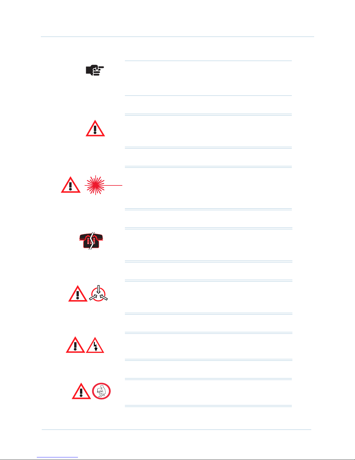
Conventions This document uses the following symbols to identify important
viii February 2003
notes, and hazardous or dangerous tasks.
Tip
Provides useful information to help you install the CPX.
Page 13
1000-A2-GN22-00 Preface
Note
The pointing finger highlights important information.
Be sure to read this information before continuing.
Warning
Alerts you to an action or inaction that could lead to an
injury to yourself or damage to the CPX-1000.
CAUTION
CLASS 1 LASER
Alerts you to a laser hazard—never look directly into the
source of a laser beam, which may be invisible.
Voice/Data Interruption
Alerts you to an action that, if done incorrectly, will interrupt
voice or data traffic.
Electro-Static Caution
Reminds you to take precautions to prevent electrostatic
damage to static-sensitive assemblies and circuits.
Danger: Shock Hazard
Alerts you to an electrical hazard that may cause fatal injury.
Caution
Alerts you to a lifting hazard that may cause physical injury.
February 2003 ix
Page 14

Preface 1000-A2-GN22-00
x February 2003
Page 15

C H A P T E R
Voice-over-Broadband
Networking
This chapter describes the Paradyne Jetstream Voice-overBroadband (VoBB) product solution, including the following
topics:
Local access network architecture (page 1-1)
CPX-1000 Voice Services Platform (page 1-3)
Packet network configuration (page 1-4)
Call origination and completion (page 1-6)
1
Local Access
Network
Architecture
CPX-1000 calling features (page 1-8)
CPX management tools and APIs (page 1-9)
The modern packet-based local access network enables Integrated
Communication Providers (ICPs) to deliver a combination of voice
and data services to their subscribers over the local loop.
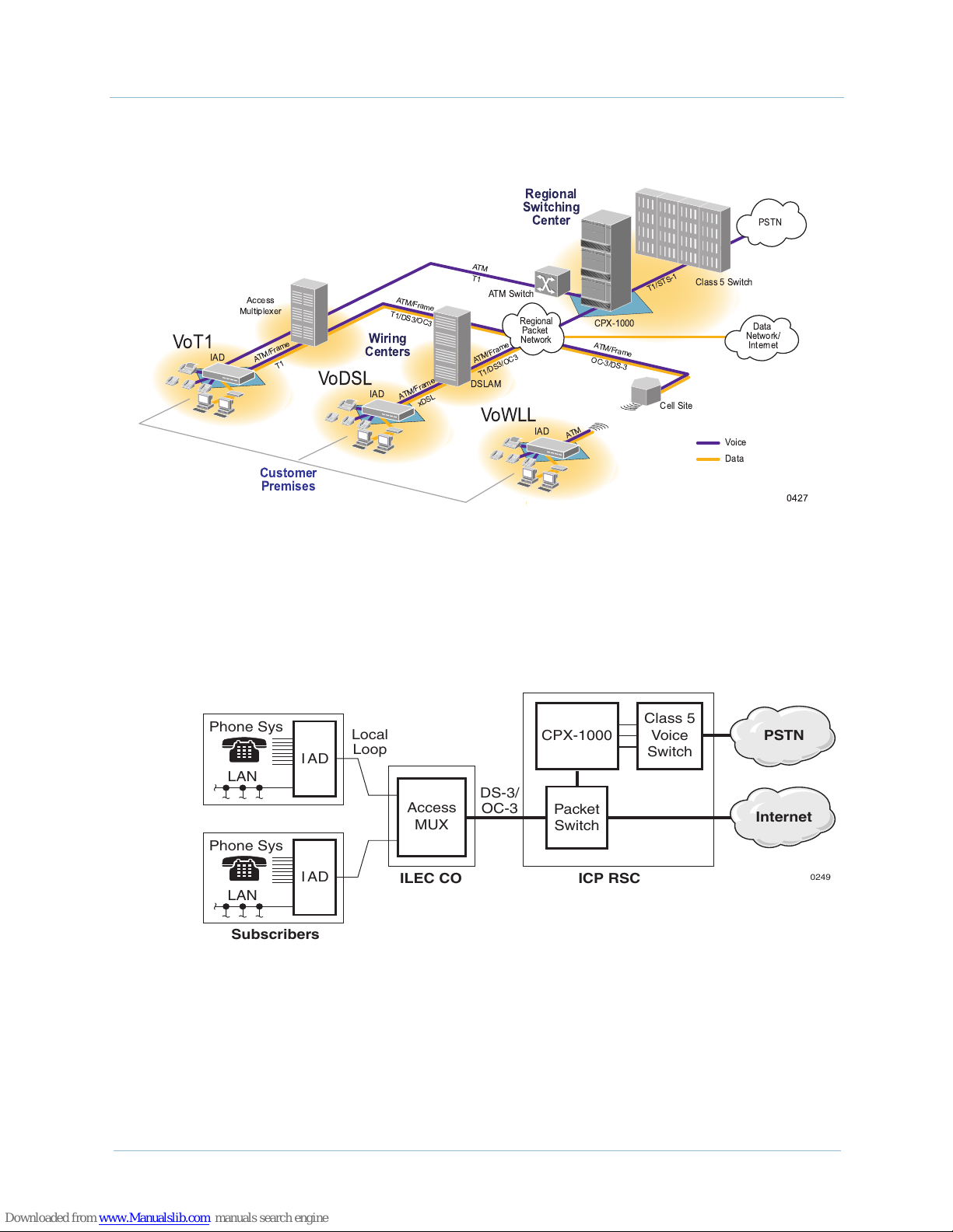
Our Voice-over-Broadband (VoBB) local access network
alternatives (Figure 1–1) include:
Voice over DSL (VoDSL)—enables the delivery of
integrated high-speed voice and data services over a single
DSL circuit; that is, over a single copper pair.
Voice over T1 (VoT1)—offers access at greater distances
(i.e., hundreds of miles when repeaters are used) and
provides guaranteed bandwidth. It also uses existing T1
aggregation resources at the ILEC central office.
Voice over Wireless (VoWLL)—eliminates the need for
land line copper loops by using ATM over MMDS or U-NII
wireless broadband access networks.
February 2003 1-1
Page 16
1. Voice-over-Broadband Networking 1000-A2-GN22-00
Regional
Switching
()
()
*+$*
Wiring
Centers
()
#
()
*+$*
Center
!"
$&'
()
+$'*'*
'
$
$ % #
Customer
Premises
Phone Sys
LAN
Phone Sys
LAN
Subscribers
Figure 1–1. VoBB Local Access Networks
The CPX-1000 Voice Services Platform is a large-scale voice
platform that resides in an ICP's Regional Switching Center (RSC).
It serves as the gateway between an ICP’s existing Class 5 voice
switch and a packet-based local access network (Figure 1–2).
Class 5
IAD
Local
Loop
CPX-1000
Voice
Switch
DS-3/
IAD
Access
MUX
ILEC CO
OC-3
Packet
Switch
ICP RSC
Internet
Figure 1–2. VoBB Network Architecture
The CPX-1000 Voice Services Platform architecture provides
seamless integration of voice and data networks. These networks
comprise standard ATM switches and local access multiplexers
available from multiple equipment manufacturers.
PSTN
0249
1-2 February 2003
Page 17

1000-A2-GN22-00 1. Voice-over-Broadband Networking
The heart of our VoBB solution is the CPX-1000. IADs, supplied by
other manufacturers, reside at subscriber premises. Each IAD
provides dial tone to standard (POTS) local telephones and data
service, using a single transmission link.
The network architecture provided by the CPX-1000 enables ICPs
to extend local dial tone services from an existing Class 5 switch
over a packet-based access network. From this perspective, as a
loop extender, voice-over-broadband is functionally similar to
traditional Digital Loop Carrier (DLC) equipment, where the Class
5 switch provides the actual dial tone, as well as Custom Local
Area Signaling Services (CLASS) and calling features.
However, unlike traditional DLCs, which supply the physical
subscriber line interface at the central office, the packet architecture
places that interface at the subscriber premises.
The benefits of this architecture are:
better voice quality, by performing analog-to-digital
conversion near the phone
CPX-1000
Voice Services
Platform
more efficient use of copper connections between the
subscriber premises and the Class 5 switch
The CPX-1000 supports any broadband access network technology,
including voice-over-T1, voice-over-DSL, and voice-over-wireless
local loop (Figure 1–1 on page 1-2).
The CPX-1000 is a carrier-class, rack-mounted shelf with
redundant components.
The CPX-1000 incorporates a scalable architecture within a single
shelf, or by using multiple CPX shelves.
A single shelf can support additional subscribers by adding
more network modules or using the spare capacity of
existing network modules.
Multi-shelf equipment is comprised of more than one CPX
when the capacity of a single shelf is exceeded.
Most shelf components are modules comprised of a line card and a
transition card. The line card installs in the front of the CPX and
the transition card installs in the rear. A passive midplane within
the CPX shelf connects the line modules and transition modules.
February 2003 1-3
Page 18
1. Voice-over-Broadband Networking 1000-A2-GN22-00
Packet
Network
Configuration
Phone Sys
LAN
Phone Sys
LAN
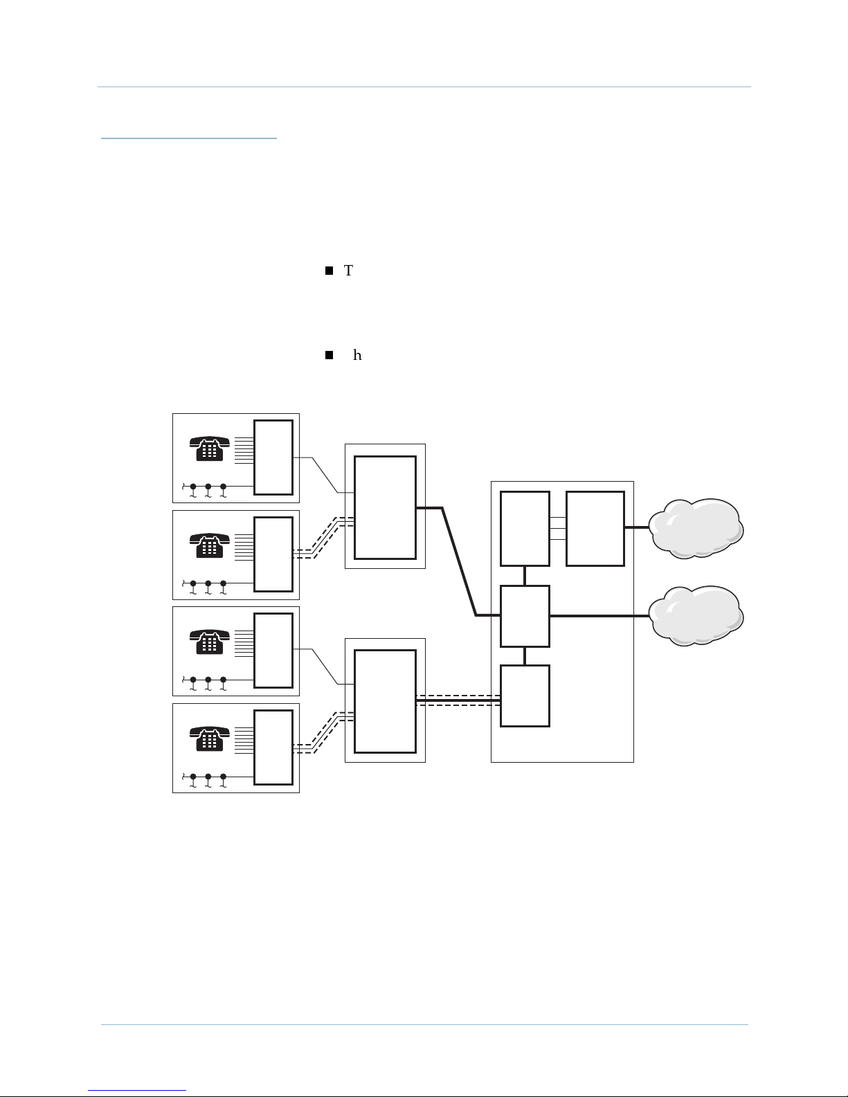
The CPX-1000 transports voice traffic via an ATM network. When
Frame Relay is used, the frames are encapsulated in ATM cells.
In the packet network (Figure 1–3), voice-over-broadband requires
a minimum of two Permanent Virtual Circuits (PVCs) across the
network for each IAD (in both ATM and Frame Relay networks).
The first PVC transports the voice and management traffic
associated with all of the subscriber's telephone lines. The
voice PVC is configured as a variable bit rate-real time
(VBR-rt) PVC, and has priority over the data PVC.
The second PVC transports the data traffic. The data PVC is
typically set up as an unspecified bit rate (UBR) PVC.
Local
IAD
IAD
Loop
AT M
Access
MUX
ILEC CO
Voice PVC
Data PVC
CPX-
1000
Class 5
Voice
Switch
PSTN
Phone Sys
LAN
Phone Sys
LAN
Subscribers
Packet
Switch
IAD
Frame
Relay
Access
MUX
IAD
ILEC CO
Voice
DLCI
Data
DLCI
FRF8
IWF
ICP RSC
Figure 1–3. VoBB Network Configuration
Internet
0250
1-4 February 2003
Page 19

1000-A2-GN22-00 1. Voice-over-Broadband Networking
Voice is more sensitive to network latency than data, so this
configuration ensures that voice traffic always has priority over
data. However, this configuration also enables voice traffic to
consume bandwidth when a call is in progress. Typically, few
subscriber's telephone lines are simultaneously in use, so the
majority of the bandwidth is usually available for data service.
For example, over a single 768 kbps symmetric DSL connection, an
ICP supports up to eight simultaneous telephone calls using 2:1
compression serving a KTS with 32 extensions at a P.01 grade of
service and still delivers data service at an average speed of
550 kbps (Figure 1–4).
700
600
Average bandwidth available for data
500
400
300
Bandwidth (K)
200
100
0
7am
8am
Average bandwidth used by telephony
9am 10am 11am 12pm 1pm 2pm 3pm 4pm 5pm
0202
Figure 1–4. Bandwidth Usage—768 kbps SDSL Circuit
However, many network operators have Frame Relay-based local
access networks interconnected with ATM networks. The CPX can
interface with the Frame Relay network through an Interworking
Function (IWF) between the Frame Relay and ATM (Figure 1–3).
The IWF is an industry-standard function that either the access
mux or a Frame Relay/ATM switch can execute.
In a Frame Relay network, each PVC uses an identifying Data Link
Connection Identifier (DLCI). ATM PVCs, however, use a Virtual
Path Identifier/Virtual Channel Identifier (VPI/VCI). The IWF
maps each Frame Relay DLCI to a corresponding ATM VPI/VCI.
February 2003 1-5
This association between the Frame Relay DLCI and ATM VPI/
VCI is made when provisioning PVCs.
Page 20
1. Voice-over-Broadband Networking 1000-A2-GN22-00
Call
Origination
and
Completion
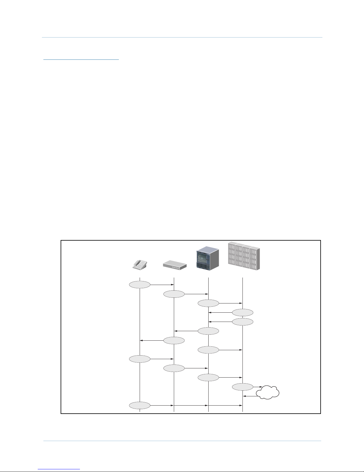
These steps describe the network interaction that occurs when a
subscriber initiates a call (Figure 1–5):
1. A subscriber initiates the call by taking the telephone off-hook.
2. The IAD notifies the CPX through the Common Channel
Signaling (CCS) channel in the voice PVC.
3. The CPX sends an outgoing call request message to the Class 5
switch through the PSTN (GR-303 protocol) Time Management
Channel (TMC).
4. The Class 5 switch selects the available time slot in a PSTN
interface group and directs the CPX to connect the IAD port to
the specified time-slot on the switch.
5. The host Class 5 switch provides dial tone.
6. The CPX cuts the calling station through to the switch.
7. The subscriber dials the destination number and the Class 5
switch collects DTMF digits.
8. The Class 5 switch routes the call, returns the call progress, and
generates a call data record.
9. The CPX notifies the Class 5 switch when the station hangs up.
Telephone IAD CPX-1000 Class 5 Switch
1
2
3
4
5
5
5
6
7
7
7
8
9
Figure 1–5. Subscriber Initiates a Call
PSTN
0352
1-6 February 2003
Page 21
1000-A2-GN22-00 1. Voice-over-Broadband Networking
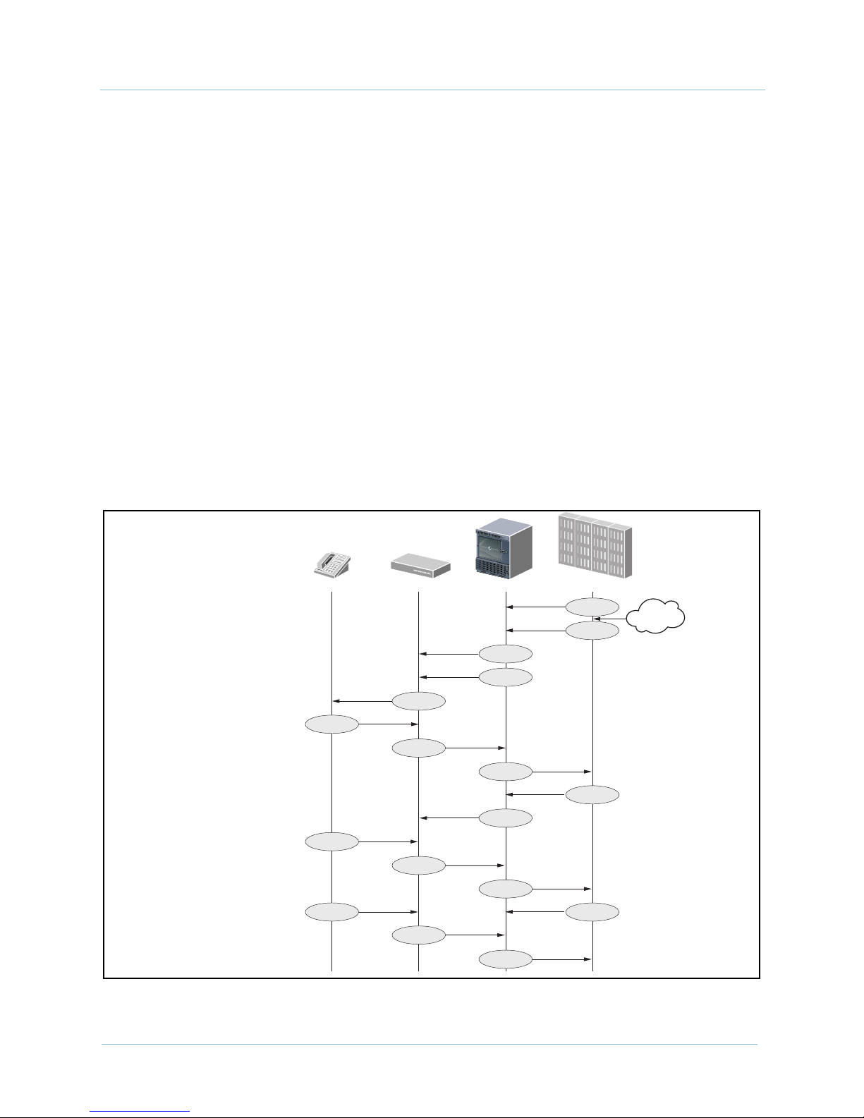
These steps describe the network interaction that occurs when a
subscriber receives a call (Figure 1–6):
1. The Class 5 switch sends an incoming call request message to
the CPX through the PSTN (GR-303) TMC.
2. The Class 5 switch assigns a time slot.
3. The CPX sends a setup message to the IAD, verifying both
bandwidth and port availability.
4. The CPX connects the specified time slot to an IAD port.
5. The IAD initiates ringing.
6. The IAD notifies the switch via the CPX when the first ring is
complete and connects the station through to the host.
7. The Class 5 switch sends a caller ID to the IAD via the CPX.
8. When the station answers, the CPX sends a call connected
message to the Class 5 switch.
9. The Class 5 switch notifies the CPX when the call is cleared.
10. The CPX notifies the switch when the station hangs up.
Telephone IAD CPX-1000 Class 5 Switch
10
1
2
3
4
5
6
6
6
7
7
8
8
8
9
10
PSTN
February 2003 1-7
10
Figure 1–6. Subscriber Receives a Call
0353
Page 22

1. Voice-over-Broadband Networking 1000-A2-GN22-00
CPX-1000
Calling
Features
The CPX transparently passes all Class 5 switch standard POTS
features to subscribers. These include:
On-hook message delivery, with power ringing (caller ID)
On-hook message delivery, without power ringing
— Visual Message Waiting Indication (VMWI)
— other messaging services, such as stock quotes
Off-hook message delivery
— caller ID
— call waiting
Flash features
— call waiting
— 3-way calling
— call hold
— call transfer
In-band calling features
— stutter dial tone for message waiting
— code-activated features
— call forwarding
— call return
Distinctive ringing
Loop battery control
— answer supervision
—toll alerting
— calling-party control
411 directory assistance
911 emergency assistance
Anonymous call rejection
Automatic call back
Call blocking
Call forward busy
Call forward no answer
Operator barge in
Privacy support—number blocking
Selective call forwarding
Speed calling
1-8 February 2003
Page 23

1000-A2-GN22-00 1. Voice-over-Broadband Networking
CPX-1000
Management
Tools and APIs
We provide several management tools and APIs for use in other
network management systems.
JetCraft
We provide a Windows-based voice service management tool with
a graphic user interface, called JetCraft. JetCraft manages one CPX
at a time. See the JetCraft User’s Guide for more information.
JetVision
We also provide a second, more extensive element management
system, called JetVision. JetVision can manage up to 50 CPX
shelves at a time. JetVision is used in a standalone configuration to
support flow-through management from a higher level Network
Management System (NMS) via the JetWay API. See the JetVision
User’s Guide for more information.
Jetway
JetWay is an API (Application Program Interface) for JetVision that
enables northbound network management systems to integrate
functionality into managerial capabilities provided by JetVision.
TL1 Agent
The TL1 Agent is an application that allows TL1 (Transaction
Language 1) messages to be sent to the CPX. TL1 is a standard
command-line interface protocol designed for element
management. The messages supported allow for alarm
management and retrieval of CPX configuration information. See
the CPX-1000 Voice Services Platform TL 1 Reference for more
information.
JetSNMP
We also provide JetSNMP, a CPX native interface that allows
SNMP Managers (e.g., HP Open View) to discover and monitor the
CPX-1000 equipment. When the CPX-1000 is purchased, we can
provide the standard Jetstream SNMP MIB file.
February 2003 1-9
Page 24

1. Voice-over-Broadband Networking 1000-A2-GN22-00
1-10 February 2003
Page 25
C H A P T E R
2
CPX-1000 Voice Services
Platform Description
This chapter describes the features, components, and overall
specifications of the CPX-1000, including the following topics:
Equipment operational features (page 2-2)
Capacity (page 2-2)
CPX-1000 operation (page 2-3)
Physical description (page 2-8)
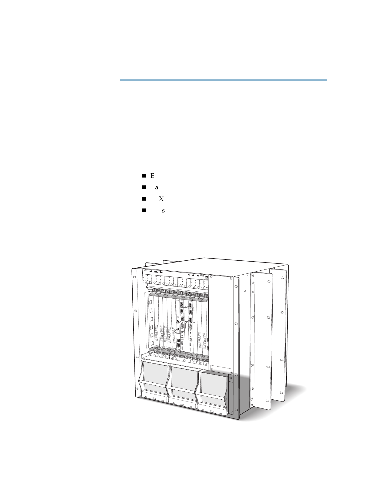
The CPX-1000 (Figure 2–1) is a carrier-class, rack-mounted shelf
that resides in an Integrated Service Provider’s (ICP's) Regional
Service Center (RSC).
A
L
E
R
T
A
A
L
E
R
T
B
A
L
E
R
T
D
IS
U
N
A
C
C
A
B
L
E
D
D
IS
A
B
L
E
D
D
IS
A
B
L
E
D
D
IS
A
B
L
E
D
D
IS
A
B
L
E
D
D
IS
A
B
L
E
L
O
C
K
E
D
U
N
L
O
T
A
C
T
1
D
C
K
E
D
U
N
L
O
C
K
E
D
U
N
L
O
C
K
E
D
U
N
L
O
C
K
E
D
U
N
L
O
C
K
E
D
A
C
T
A
C
T
A
2
C
T
A
C
T
3
4
5
6
1
2
3
4
5
M
IN
O
RM
A
J
O
R
C
R
IT
IC
A
D
IS
A
B
L
E
D
D
IS
A
B
L
E
D
D
IS
A
B
L
U
N
L
O
C
K
E
D
U
N
L
O
C
K
E
D
U
N
L
O
C
A
C
T
A
C
T
A
C
T
7
8
9
6
7
L
E
D
D
IS
A
B
L
E
D
D
IS
A
B
L
E
D
D
IS
A
B
L
E
D
D
IS
A
B
L
E
D
D
IS
A
B
L
E
D
D
IS
A
B
K
E
D
U
N
L
O
C
K
E
D
U
N
A
C
T
A
C
10
9
L
E
L
O
T
D
C
K
E
D
U
N
L
O
C
K
E
D
U
N
L
O
C
K
E
D
U
N
L
O
C
K
E
D
U
N
L
O
C
K
E
D
A
C
T
A
C
T
A
C
T
11
A
C
T
12
13
14
15
11
12 13
14
Figure 2–1. CPX-1000 (Front View)
0484
February 2003 2-1
Page 26

2. CPX-1000 Voice Services Platform Description 1000-A2-GN22-00
A CPX installation is scalable: first by populating an individual
shelf, then by adding additional shelves. Each CPX shelf occupies
12 RU (21 inches high) and is 17 inches deep.
Using optional mounting brackets, the shelf can be installed in
19-inch EIA310, Bell Wide, Bell Narrow, and NEBS2000 racks.
Reversible mounting brackets allow installation in 23-inch racks.
Equipment
Operational
Features
A single CPX-1000 can manage than 18,800 subscriber telephone
lines (at 9:1 concentration ratios) on a voice-over-broadband
network, including:
Circuit-to-packet conversion—converts DS0s from the
Class 5 switch into cell-based ATM format.
Routing—routes cells to and from IADs at subscriber
locations.
Call administration—manages call-control signaling to
both the Class 5 switch and the IADs.
Traffic management—monitors the connection over the
access network to each end user.
Concentration management—supports line
concentration levels up to 40:1.
System and Service Administration—acts as the
administrative platform for managing voice-over-packet
services.
Traffic
Capacity
2-2 February 2003
The CPX supports up to 4,000 IADs, and supports two types of T1
modules, which may be used interchangeably: The Octal T1
module provides 8 T1 ports, and up to 6 modules may be placed in
the CPX. Echo cancellation or echo cancellation and compression is
provided on separate cards. The 12-port T1 ECAC module
provides 12 T1 ports, and up to 7 modules may be placed in the
CPX. Also, echo cancellation and compression is provided directly
onboard, eliminating the need for separate EC or ECAC cards.
The CPX also supports two types of STS-1 cards, which may be
used interchangeably. Up to 6 STS-1 cards may be installed in each
CPX. The STS-1 module does not provide onboard echo
cancellation or compression—you must use separate modules. The
STS-1 ECAC module includes onboard echo cancellation and
compression, eliminating the need for separate EC or ECAC cards.
Page 27

1000-A2-GN22-00 2. CPX-1000 Voice Services Platform Description
The capacity of the CPX shelf configured with either T1 modules
depends on the shelf configuration and the concentration and
redundancy options selected.
A CPX shelf using either STS-1 or 12-port T1 card with ATM OC-3
can support over 2,000 simultaneous calls and 16,000 subscriber
lines (8:1 concentration).
Carriers can upgrade the CPX network by adding additional
CPX-1000s, all of which can be managed by a single JetVision
workstation.
CPX-1000
Operation
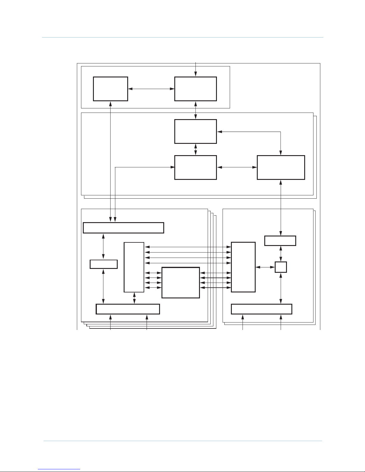
Call control, circuit-packet switching, network interfaces,
provisioning, and management, are divided into four basic
functional blocks:
Management processing (MP)
Call Processing (CP)
PSTN interface (T1 or STS-1)
Packet interface
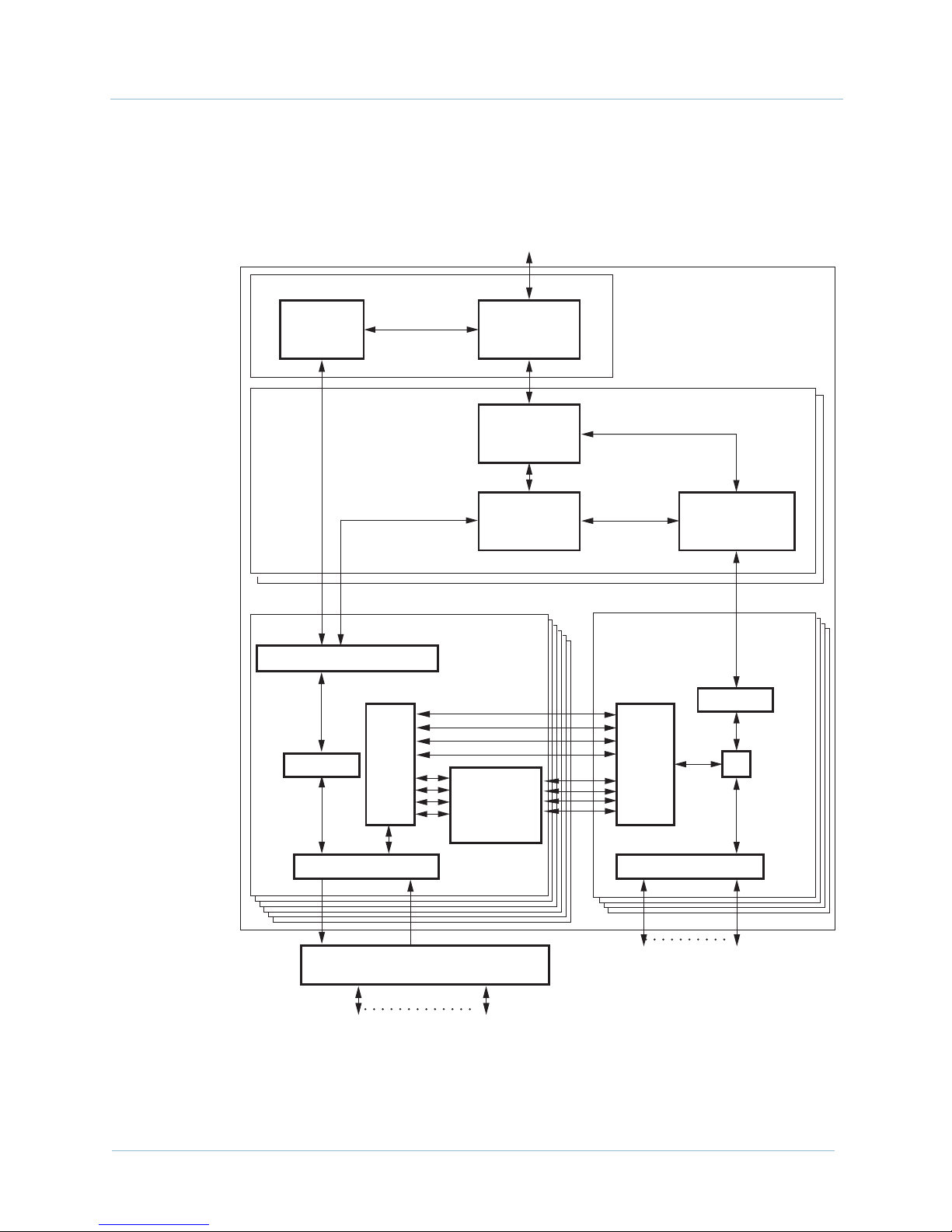
Figure 2–2 illustrates this functionality when providing access to
the PSTN via T1, using the 12-port T1 ECAC module.
February 2003 2-3
Page 28
2. CPX-1000 Voice Services Platform Description 1000-A2-GN22-00
MP Module
EOC
Process
CP
Modules
PSTN Interface
T1 Modules
Q.931 (LAPD) Link Layer
Management
Process
Call
Processing
Engine
TMC
Processing
Voice Bus
CPX-1000
Shelf
IAD
Signalling and
Connectivity
Packet Interface
ATM Modules
Control
Control
Voice Voice
T1 Interface Controller
Figure 2–2. CPX Functional Diagram (T1 Interface)
Echo
Cancellation
and
Compression
Voice/
Control
Splitter
OC3 Port
0481
2-4 February 2003
Page 29
1000-A2-GN22-00 2. CPX-1000 Voice Services Platform Description
Figure 2–3 illustrates this same functionality when providing
access to the PSTN via STS-1, using the STS-1 ECAC module.
LAN Connection To/From
Network Management System
MP Module
EOC
Process
CP
Modules
Q.931 (LAPD) Link Layer
Management
Process
Call
Processing
Engine
TMC
Processing
PSTN Interface
STS1 Modules
Voice Bus
CPX-1000
Shelf
IAD
Signalling and
Connectivity
Packet Interface
ATM Modules
Control
Control
STS-1 Interface
Voice Voice
PSTN Lines To/From
Class 5 Switch
Figure 2–3. CPX
Splitter
Echo
Cancellation
and
Compression
OC3 Port
ATM Lines To/From
Packet Switch
Functional Diagram (STS-1 Interface)
Voice/
Control
Splitter
0420
February 2003 2-5
Page 30

2. CPX-1000 Voice Services Platform Description 1000-A2-GN22-00
Management
Processing
The Management Processor (MP) module is the administrative
CPU for the CPX shelf. It acts as a database for the shelf and as an
administrative interface for JetCraft, JetVision, and other
management interfaces. The MP supports:
Configuration, fault, and security management for the CPX
Configuration management, fault management, and remote
software upgrade of the IADs
High-performance, memory-resident database for persistent
configuration
Real-time performance and error statics
The Embedded Operations Channel (EOC) process on the MP
module handles the interface between the CPX shelf and the GR303 interface on the Class 5 switch. The EOC supports the
following set of management services to the switch using the T1
model and GR-303 protocol stack:
1. The EOC process receives the management requests over the
EOC connection to the switch.
2. It then interacts with the management process to complete
these requests.
3. The management process notifies the EOC process about
changes in the operating status of the CPX-managed objects.
4. The EOC process sends this information to the Class 5 switch.
Call Processing The Call Processor Engine manages the connections between the
CPX shelf and the IADs at subscriber premises.
The Call Processor Engine resides on the redundant Call Processor
(CP) modules that handle call processing, call-control signaling,
call setup, and call tear-down.
The Timeslot Management Channel (TMC) process on the CP
modules receive all call control signaling from both the Class 5
switch and the CP using the Q.921 (LAPD) data link protocol.
The IAD Signaling and Connectivity function manages
communication between the CPX and the IADs. The information
passed between the CPX and each IAD includes common channel
signaling, alarms and events, and software downloads.
PSTN Interface The PSTN interface connects the CPX to the Class 5 switch via T1
or STS-1 lines. The Port Controller inserts framing and supervision
signals into the TDM data stream. The PSTN interface then directs
2-6 February 2003
Page 31

1000-A2-GN22-00 2. CPX-1000 Voice Services Platform Description
all signaling to both the TMC process and the CP. The PSTN
interface controls all time slot mapping and CP functions.
The PSTN routes all voice timeslots over the voice bus to the
packet interface.
The Voice Processing function switches individual timeslots
between the TDM (T1/STS-1) ports and the voice bus. The Voice
Processing function maps all incoming and outgoing voice data
streams.
Packet Interface The packet interface physically connects the CPX shelf to the
packet network. The interface provides TDM data transport
services over ATM using standard ITU and ATM Forum-compliant
communications protocols.
This interface converts the information on the Bearer Bus to
standard ATM cells and transmits these cells on the packet
network. It also converts packet cells to voice timeslots. The
Voice/Control Splitter directs the ATM cells (which contain call
control and signaling) through the IAD Signaling and Connectivity
function to the Call Processor Engine.
The CPX supports up to 4,096 unique PVCs (each representing one
IAD). Each PVC (i.e., IAD) has a unique VPI and VCI assigned to
it. The CPX supports 256 VPIs in the range of 0 to 255. IADs can be
provisioned on any of these VPIs. The permissible range of VCIs
per VPI is 0 to 1023. The maximum number of VCIs per VPI can be
configured as one of five possible settings when the equipment is
initially configured. The possible settings are:
1,024 (default)
512
256
128
64
Selection of the maximum of VCIs is determined by the network
planner for what best fits the network topology.
In order to afford the maximum number of PVCs available from
the CPX, IADs can be organized into IAD Groups. Groups are
logical entities where IADs meet these criteria:
provisioned with differing VPIs but the same VCI
February 2003 2-7
Page 32

2. CPX-1000 Voice Services Platform Description 1000-A2-GN22-00
the remainder of the formula is the same for all IADs:
VPI
(1024/VCIs per VPI)
For example, consider three IADs with the VPI/VCI pairs and
where the maximum number of VCIs configured for the
equipment is 256:
A. 32, 100
B. 36, 100
C. 38, 100
1. All three have the same VCI.
2. The maximum number of VCIs possible (1,024) divided by
the number of VCIs configured (256) equals 4.
3. Pairs A and B yield a result with no remainder when their
VPIs (32 and 36, respectively) are divided by the resultant of
1024 divided by 256: 32/4 = 8 with a remainder of 0 and
36/4=9 with a remainder of 0. (Pair C yields a different
remainder: 38/4=9, remainder 2. Therefore, it is not in the
same group with A and B.)
Physical
Description
A maximum 4,096 IADs can be assigned. However, only 63
simultaneously active calls through IAD unlocked ports are
allowed in any one IAD Group.
Note
IAD ports can be over-provisioned; however, only 63
can obtain dial tone at one time.
The CPX hardware consists of these items (Figure 2–4):
CPX shelf (Figure 2–4)
Summary alarm panel (detail, page 2-10)
Line modules—line cards and transition cards for T1 or
STS-1 (beginning on page 2-19)
STS-1 Splitter Assembly (when STS-1 equipped)
DC Power Supply Fan and Fan modules (page 2-37)
DC power distribution panel (page 2-39)
2-8 February 2003
Page 33

1000-A2-GN22-00 2. CPX-1000 Voice Services Platform Description
Front
ALERT A
ALERT B
Summary Alarm Panel
ALERT C
D
IS
ABL
ED
D
ISA
B
LED
D
ISAB
LED
DIS
ABLED
D
ISA
B
LED
D
U
N
LO
CKE
D
UN
LOC
KE
D
U
NLO
C
KE
D
UN
LO
CK
ED
U
N
LO
CK
ED
UNL
ACT
AC
T
AC
T
1
A
CT
AC
2
T
3
4
5
M
IN
O
R
MA
JO
R
C
R
ITICA
IS
AB
L
ED
DISAB
LE
D
D
IS
AB
L
ED
O
CK
E
D
UN
LOC
KE
D
UNL
O
CK
A
CT
A
CT
AC
T
6
7
8
L
D
IS
AB
LED
DIS
AB
LED
DISA
B
LED
D
IS
AB
LE
D
D
IS
ABLED
DISA
BL
ED
U
N
LO
AC
T
ED
D
ISA
CK
ED
U
NLO
AC
9
BLE
D
C
KED
UN
LO
C
KE
D
U
NL
OC
KE
D
U
NLO
CK
ED
U
NL
O
CKE
D
U
N
LO
C
KE
T
10
D
A
CT
A
CT
A
C
T
A
CT
11
A
C
T
12
13
14
15
Module Cage
1
2
3
4
56
7
9
1
1
12
13
14
Power Supply/Fan
Assemblies
Rear
Module Cage Rear View
Power Distribution
1
2
3
4
5
6
7
8
9
10
11
12
13
14
Plant Battery Terminals
Grounding Phillips Screws
Figure 2–4. CPX-1000 Front and Rear Views
0485
February 2003 2-9
Page 34

2. CPX-1000 Voice Services Platform Description 1000-A2-GN22-00
CPX-1000 Shelf Each CPX shelf is 12 RU (21 inches) high and 17 inches deep. The
shelf can mount in either a 19-inch Electronic Industries
Association (EIA) rack or a 23-inch rack.
The CPX shelf is a forced-air cooled Network Equipment Building
Standard (NEBS) Level 3-compliant platform with:
16-slot midplane
DC power input panel
Alarm panel
Three hot-swappable power supplies
The midplane is the interconnect for all 16 slots, power
distribution, and alarm signal distribution. The CPX midplane
accepts line cards, processing modules, and rear mounted
transition modules.
The power supplies (including integral fan assemblies) are located
below the card cage (accessible from the front of the shelf).
System Alarm
Panel
Alarm
Panel
The CPX alarm panel is located on the top front of the shelf.
Indicators display the current operating status of the shelf and an
alarm connector outputs to remote Telco alarm equipment
(Figure 2–5). The CPX includes three types of indicators:
Slot Status indicators for all 16 slots
System Status indicator for system status
Telc o ala rms
Table 2–1 lists the description and status of each group.
System Status Indicators Telco Alarm Indicators
SYSTEM ALERTS TELCO
ALERT A ALERT B MINOR
DISABLED
DISABLED
UNLOCKED
ACT
1
DISABLED
UNLOCKED
UNLOCKED
ACT
ACT
23456
DISABLED
UNLOCKED
ACT
ALERT C
DISABLED
UNLOCKED
ACT
DISABLED
UNLOCKED
ACT
DISABLED
UNLOCKED
ACT
7
DISABLED
UNLOCKED
ACT
8
DISABLED
UNLOCKED
ACT
9
DISABLED
DISABLED
UNLOCKED
UNLOCKED
ACT
ACT
11 12 13 14
10
MAJOR CRITICAL
DISABLED
UNLOCKED
ACT
DISABLED
UNLOCKED
ACT
DISABLED
UNLOCKED
ACT
ALARM
DISABLED
UNLOCKED
ACT
15
Slot Status Indicators
Figure 2–5. System Alarm Panel
DISABLED
UNLOCKED
ACT
16
0233-01
2-10 February 2003
Page 35

1000-A2-GN22-00 2. CPX-1000 Voice Services Platform Description
Table 2–1. Alarm Indicator Status and Description
Alarm Indicator Status Description
Slot Status Act
Unlocked
Disabled
System Status Alert A
Alert B
Alert C
Tel co Sta tu s Mi no r
Major
Critical
The three Telco alarms and a rack alarm are also routed through a
dry contact relay to the RJ-45 remote alarm connector.
The standard Telco alarm signals and rack alarm are available as an
output to remote alarm equipment (Table 2–2).
Table 2–2. Remote Alarm Connector
Module is in Active state (not Standby)
Module administrative state is Unlocked
Module operational state is Disabled
Not used
Not used
Not used
CPX minor alarm
CPX major alarm
CPX critical alarm
Pin Signal
1Critical Alarm
2 Critical Alarm Return
3Major Alarm
4Major Alarm Return
5Minor Alarm
6Minor Alarm Return
7 Rack Alarm (not used)
8 Rack Alarm Return (not used)
February 2003 2-11
Page 36

2. CPX-1000 Voice Services Platform Description 1000-A2-GN22-00
Line Modules
with T1
Line Modules
with STS-1
When configured with T1, the CPX may contain the following
module types:
Call Processor (CP) module (page 2-13)
Management Processor (MP) module (page 2-17)
Octal T1 module (page 2-19)
12-port T1 ECAC module (page 2-23)
ATM OC- 3 modul e ( page 2-32)
Echo Cancellation (EC) module (page 2-35)
– or –
Echo Cancellation and Compression module (ECAC)
(page 2-36)
The EC and ECAC modules are used only with the Octal T1
module. The 12-port T1 ECAC module provides onboard echo
cancellation and compression. See Chapter 3, Installing the CPX-
1000 for more information.
When configured with STS-1, the CPX contains the following
module types:
Call Processor module (page 2-13)
Management Processor module (page 2-17)
STS-1 module with Echo Cancellation (page 2-25)
STS-1 ECAC module with Echo Cancellation and
Compression (page 2-28)
ATM OC- 3 modul e ( page 2-32)
Echo Cancellation and Compression module (page 2-36)
The ECAC module is used only with the STS-1 module. The STS-1
ECAC module provides onboard echo cancellation and
compression. See Chapter 3, Installing the CPX-1000 for more
information.
2-12 February 2003
Page 37

1000-A2-GN22-00 2. CPX-1000 Voice Services Platform Description
Call Processor
Modules
The CPX shelf supports two CP modules in an active/standby
configuration, made up of two cards (Figure 2–6):
Call Processing card—contains a processor, plus volatile
and non-volatile RAM.
Hot Swap Controller (HSC) card—maintains each
module’s status, controls power and each module’s reset,
monitors and controls peripherals, including power/fan
modules, board and system indicators/alarms.
CP2
RJ-45
Ethernet Port
Receive
Link
Status
LEDs
Control
Processor
Card
PCI MEZZANINE CARD
LNK1ACT
2
LNK
ACT
10/100
ETHERNET
Hot Swap
Controller
Card
PWR
ERROR
Transmit
RST
ABT
BFL
CP Status LEDs
CPCI
USB 1COM 110/100 BASE T USB 0
CPU
PCI
Figure 2–6. Call Processor Module
0483
February 2003 2-13
Page 38

2. CPX-1000 Voice Services Platform Description 1000-A2-GN22-00
Table 2–3 lists the function of each control, port, and indicators.
Table 2–3. CP Module Controls, Indicators, and Ports
Card Controls, Indicators, and Ports Function
Call Processor (CP)
T64 1 ETHERNET
Connects to CP A module’s Ethernet
port
Link (green)
ACT (Amber)
T64 2 ETHERNET
Link is established
Ethernet circuit is in use
Connects to CP B module’s Ethernet
port
LINK (green)
ACT (Amber)
10/100 BASE T Connects to MP card
COM 1 Not used
RST Resets the CP module and may reset
Link is established
Ethernet circuit is in use
the shelf—DO NOT USE
ABT Not used
BFL Lights yellow when board fails
CPU Lights green when there is CPU
activity
CPCI Lights green when there is cPCI bus
activity
PCI Lights green when there is PCI bus
activity
USB 1 Not used
USB 2 Not used
Hot Swap Controller
PWR CP and HSC cards are powered
(HSC)
ERROR Lights when there is an HSC error
2-14 February 2003
Page 39

1000-A2-GN22-00 2. CPX-1000 Voice Services Platform Description
The CPX supports redundant CP modules (Figure 2–7).
LAN
MP
T1 EC ATM
T1
LAN
MP
CPX-1000
CP-BCP-A
AT M
CPX-1000
CP-BCP-A
Before
Switchover
(CP-A is Active,
CP-B is Standby)
After
Switchover
(CP-A is Standby,
CP-B is Active)
T1 EC ATM
T1
AT M
0242
Figure 2–7. Call Processor Redundancy
On power up, the primary CP (in the lower numbered slot
— slot 7) is the active CP and the secondary CP (in the
higher numbered slot — slot 9) is the standby CP.
The active CP module handles all call processing activity,
maintains all signaling, manages all IADs, captures statistics
and alarms, and monitors all hardware in the system. It
passes all this information to the management system.
The standby CP module mirrors the state information of
the active CP module (i.e., all of the activity on the active CP
module) and can take over at any time.
February 2003 2-15
Page 40

2. CPX-1000 Voice Services Platform Description 1000-A2-GN22-00
This architecture enables two types of CP module switchovers:
Automatic switchover—the system detects a problem
with the active CP module and performs a forced
switchover to the standby CP module. Mechanisms used to
detect problems with a CP module include:
— Loss of a CP-to-MP (Management Processor) module
heartbeat
— Loss of a CP-to-CP module heartbeat
— Failure of a CP to respond to an “are you alive” ping
request from the High Availability software
— Failure of the High Availability software to detect a ping
request from the ping component on a CP module
Administrative switchover—the network administrator
initiates a CP switchover using JetCraft or JetVision. A
forced switchover always goes through regardless of voice
traffic and active cells remain up.
Voice/Data Interruptionœ – possible
Calls that are in setup process are lost during a forced
switchover. Calls that are already established and carrying
voice traffic continue during a switchover.
Upon initiating a switchover, the previously active CP’s calls are
assumed by the new active CP. After the switchover, the old active
CP assumes the standby role (if all is well). CP switchovers do not
automatically revert back.
2-16 February 2003
Page 41

1000-A2-GN22-00 2. CPX-1000 Voice Services Platform Description
Management
Processor
Module
The Management Processor (MP) module contains a processor,
volatile and non-volatile RAM, and an Ethernet interface for
administration.
The MP module is the administrative engine of a CPX shelf. It acts
as a database for the shelf and as the administrative interface for
JetCraft, JetVision and other management interfaces.
The MP module consists of two individual cards (Figure 2–8):
Management Processing card—processor and
interface connections for monitoring redundant CP
modules.
MP Transition card—I/O ports for connecting to the local
area network and other peripheral devices.
The MP module hosts the CPX Management Entity, which features
and supports:
Configuration, fault, and security management for the CPX
Configuration management, fault management, and remote
software upgrade of the IADs
High-performance, memory-resident database for
configurations persistence
Real-time performance and error statics
Two Ethernet ports are provided on the MP Card. Each port
provides one connection to the CP A and B modules, configured to
run at 100BaseTX Full Duplex. Each Ethernet port supports
10BaseT, 10BaseT Full Duplex, 100BaseTX, and 100BaseTX Full
Duplex media types. It can detect the network media type to which
it is connected, when the AutoDetect mode is selected
(recommended in most cases).
On the MP Transition card, there are also 2 Ethernet connections, 1
and 2. Ethernet 1 is enabled and Ethernet 2 is disabled. On the front
of the MP, there is also a third Ethernet connection marked
“Ethernet”, which is the same as Ethernet 1 on the back. The back
port is active, but the front Ethernet port is not active (unless there
is no MP Transition card present).
Table 2–4 lists the function of each control, port, and indicators.
February 2003 2-17
Page 42

2. CPX-1000 Voice Services Platform Description 1000-A2-GN22-00
Transmit
Link
Status
LEDs
Receive
Management
Processor
(Shelf Front)
ETHERNET
LNK1ACT
2
LNK
ACT
10/100
ETHERNET
ETHERNET
COM 1
V
I
P
M
C
2
P
M
C
1
D
E
O
C
O
M
2
ETHERNET 2
ETHERNET 1
P
I
M
1
Management
Processor
Transition
Card
(Shelf Rear)
RESET
PWR
EXT
0449
Figure 2–8. Management Processor Module
2-18 February 2003
Page 43

1000-A2-GN22-00 2. CPX-1000 Voice Services Platform Description
Table 2–4. MP Module Controls, Indicators, and Ports
Card Controls, Indicators, and Ports Function
Management
Processor Card
(Front)
T64 1 ETHERNET
Link (green)
ACT (Amber)
T64 2 ETHERNET
LINK (green)
ACT (Amber)
ETHERNET
COM1
RESET
Connects to CP A module’s Ethernet
port
Link is established
Ethernet circuit is in use
Connects to CP B module’s Ethernet
port
Link is established
Ethernet circuit is in use
Connects to LAN or PC for access to
network management systems. Port
is only in service when no MP
transition card is present.
Connects to PC via serial cable for
network management via
HyperTerminal.
Press to restart processor
MP Transition Card
EXT
PWR
Keyboard/Mouse Port
Hot swap
MP and MP transition cards powered
Not used
(Rear)
VIDEO
COM 2 Connects to a modem for Paradyne
Not used
support only
ETHERNET 2
ETHERNET 1
Not used
Connects to LAN or PC for access to
network management systems.
February 2003 2-19
Page 44

2. CPX-1000 Voice Services Platform Description 1000-A2-GN22-00
PSTN Modules The CPX provides complete support of the GR-303 protocol,
including full GR-303 line concentration, all CLASS and calling
features, full EOC, TMC, and path protection switching.
The CPX supports eight T1 interface groups (IGs). Each T1 port is
independently assigned to an interface group, and each interface
group supports up to 28 T1 ports. The CPX also supports path
protection switching for the control channels in the GR-303
interface group.
T1 Load Sharing T1 load sharing is implemented by designing in excess capacity.
Overcapacity protection means the capacity of the T1 interface is
maintained when one of the following failures occurs even at the
busy hour call volume:
T1 module failure—oversize the capacity of the T1
interface for a fully operational system (Figure 2–9A) so that
the interface can still handle the busy hour call volume even
when one of the T1 modules has failed (Figure 2–9B).
T1 port failure—interface groups comprise T1 ports and
are arranged across T1 modules so that IGs are shared
among T1 modules (Figure 2–10). The shared arrangement
provides a backup T1 port to each T1 module should one of
the IG groups fail.
The illustrations below show how to implement primary and
secondary module pairs, and group the T1 ports in Interface
Groups across the cards, using Octal T1 cards for clarity.
When implementing PSTN using 12-port T1 ECAC modules, you
attach the RJ-21X cable from each 12-port T1 card to a patch panel
to split out each T1 port separately for connection as usual. T1
modules are paired as primary and secondary modules, and group
the T1 ports into Interface Groups across cards in the same manner.
Caution
Do not put primary and secondary DS1 links on the same T1
module. Doing so prevents new calls from being made if
one T1 module fails.
2-20 February 2003
Page 45

1000-A2-GN22-00 2. CPX-1000 Voice Services Platform Description
T1 Modules
(all operational)
A. Full Capacity
(all TDM modules operational)
Primary
Secondary
IG #1
IG #2
T1 Modules
(single failure)
B. Diminished Capacity
(one TDM module failed -
TDM interface must still be able
to handle busy hour call volume)
Primary
Secondary
IG #1
IG #2
0228
Figure 2–9. T1 Module Path Protection Switching
T1 Modules
IG #1
IG #2
0271
Figure 2–10. T1 Port Failure Protection
Octal T1 Module The Octal T1 module supports eight T1 interfaces to the Class 5
switch.
The T1 module consists of two separate cards (Figure 2–11):
February 2003 2-21
Page 46

2. CPX-1000 Voice Services Platform Description 1000-A2-GN22-00
T1 Processing card—processor that controls T1
processing.
T1 Transition card—provides eight T1 interfaces via RJ48C jacks (1 through 8), plus a Line Interface Unit (LIU) to
insert framing and supervision signals into the T1 data
stream.
Table 2–5 describes the controls, indicators, and ports of the Octal
T1 module ports and indicators.
FAILRUN
15
26
37
48
PORTS
Ethernet
DIAG
LINKACT
0161
Octal T1
T1 Transition Card
2-22 February 2003
Figure 2–11. Octal T1 and Transition Cards
Page 47

1000-A2-GN22-00 2. CPX-1000 Voice Services Platform Description
Table 2–5. Octal T1 Module Controls, Indicators, and Ports
Cards Controls, Indicators, and Ports Function
Octal T1 RUN Lights green when processor is active
FAIL Lights if module fails
T1 Port Indicators (8) Lights if carrier fails or no carrier is
present on the indicated port
ACT Not used
LINK Not used
Ethernet Not used
DIAG Reserved for factory use only
T1 Transition
12-Port T1 ECAC
Module
Power Both cards are powered
8 RJ-48C jacks For T1/DS1 cables to Class 5 switch
The 12-port T1 Echo Cancellation And Compression (ECAC)
module supports twelve T1 connections to the Class 5 switch via
an RJ-21X port, plus onboard echo cancellation and compression.
The 12-port T1 ECAC module consists of two separate cards
(Figure 2–11):
12-port T1 ECAC Processing card—performs T1
processing, plus onboard echo cancellation and
compression.
T1 Transition card—provides twelve T1 interfaces via the
RJ-21X port (attached to a patch panel), plus a Line Interface
Unit (LIU) that inserts framing and supervision signals into
the T1 data stream.
Table 2–6 describes the controls, indicators, and ports of the
12-port T1 ECAC module ports and indicators.
February 2003 2-23
Page 48

2. CPX-1000 Voice Services Platform Description 1000-A2-GN22-00
TDM-12E1/T1
12 PORT T1
RJ-21X
Port
12-port T1
ECAC Card
12-port
T1 ECAC
10 BT ETH
S
A
T
C
A
T
T
2
1
4
3
6
5
8
7
910
11 12
BITS
PCM TEST
RS-232
HOT
SWAP
0478
0479
Figure 2–12. 12-port T1 ECAC and T1 Transition Cards
2-24 February 2003
Page 49

1000-A2-GN22-00 2. CPX-1000 Voice Services Platform Description
Table 2–6. 12-port T1 ECAC Module Controls, Indicators, and Ports
Cards Controls, Indicators, and Ports Function
12-port T1 ECAC STAT Lights green when processor is active
ACT Lights green if module is in active
group
T1 Port Indicators (12) Lights red if carrier fails, or no carrier
is present on the indicated port
Hot Swap
12-port T1 Transition
RJ-21X PORT for 12 T1s
10 BT ETH RJ-48C port Unused
BITS RJ-48C port For onsite BITS clocking source
PCM TEST RJ-48C port Unused
RS-232
For T1 cable to Class 5 switch
Unused
STS-1 Module The STS-1 module consists of two cards (Figure 2–14) that supports
one STS-1 interface containing 672 DS0s (28 DS1s) in a single
physical interface. This interface may be connected directly to the
Class 5 Switch, or it may be routed through an external STS-1 mux
before being connected to the switch.
STS-1 Processing Card—processor that controls the 28
DS1s within an STS-1 circuit.
STS-1 Transition Card—provides the STS-1 interface via
Tx and Rx coaxial connections, plus a BITS timing interface.
The STS-1 card features on-board echo cancellation. If compression
is required, an Echo Cancellation and Compression card may be
added. Debug interfaces are also provided.
February 2003 2-25
The STS-1 module increases the traffic capacity of the CPX over
what can otherwise be obtained by using T1 modules. When
configured for redundancy (1 + 1), these modules occupy shelf
slots 11-16 in pairs.
Page 50

2. CPX-1000 Voice Services Platform Description 1000-A2-GN22-00
STS-1 Card STS-1 Transition Card
P
C
M
Status
TX
T
E
S
T
B
T
S
O
S
A
T
C
A
T
T
T
R
X
X
Activity
RX
RS-232
PROT
SWITCH
PCM Test Port
I
BITS Port
I
B
T
10BaseT
E
T
H
Ethernet Port
RS-232C Port
Protection
Switching Port
Hot Swap
Indicator
STS-1 Ports
TX
Hot
Swap
RX
0421
Figure 2–13. STS-1 Module
As with a T1-based configuration, the STS-1 configuration
provides complete support for the GR-303 protocol including full
GR-303 line concentration, CLASS and calling features, full EOC,
TMC and path protection switching.
2-26 February 2003
Page 51

1000-A2-GN22-00 2. CPX-1000 Voice Services Platform Description
A single CPX shelf supports eight interface groups (IGs) with each
port independently assigned to an interface group. Each interface
group supports up to 28 DS1 ports. The CPX also supports path
protection switching for the control channels in the GR-303
Interface group.
Table 2–7 describes the controls, indicators and ports of the STS-1
module ports and indicators.
Table 2–7. STS-1 Module Controls, Indicators, and Ports
Cards Controls, Indicators, and Ports Function
STS-1 STATus Lit solid green when fully initialized.
Flashing red indicates board error
ACTivity Lit green when card is active. Unlit
when card is in standby mode.
STS-1 Transition
TX
RX
Hot Swap
PCM Test Port
BITS
10BaseT Ethernet
RS-232C
Protection Switching
Lights solid green when transmitting
data. Lights flashing red when
SONET Far End Section receive
failure is indicated. Unlit when STS-1
port is not enabled.
Lights solid green when receiving
data. Lights flashing red if a Loss-ofSync (LOS) or Loss-of-Frame (LOF) is
detected at the physical interface.
Unlit when STS-1 port is not enabled
Lights blue when card is unlocked.
Unlit when card is locked.
Unused
Used for onsite BITS clocking source
Unused
Unused
Unused
TX STS-1 Port
RX STS-1 Port
February 2003 2-27
Used to transmit data to Host Class 5
switch RX STS port.
Used to receive data from Host Class
5 switch TX STS port.
Page 52

2. CPX-1000 Voice Services Platform Description 1000-A2-GN22-00
STS-1 ECAC Card The optional STS-1 ECAC module consists of two cards
(Figure 2–14) that support one STS-1 interface containing 672 DS0s
(28 DS1s) in a single physical interface, and includes onboard echo
cancellation and compression. This interface may be connected
directly to the Class 5 Switch, or it may be routed through an
external STS-1 mux before being connected to the switch.
STS-1 ECAC Processing Card—controls the 28 DS1s in
an STS-1 circuit, plus onboard echo cancellation and
compression.
STS-1 Transition Card—provides the STS-1 interface via
Tx and Rx coaxial connections, plus a BITS timing interface.
STS-1 ECAC Card
Status
TX
STS-1 Transition Card
P
C
M
T
PCM Test Port
E
S
RS-232
PROT
SWITCH
TX
T
B
I
T
S
I
O
B
T
E
T
H
BITS Port
10BaseT
Ethernet Port
RS-232C Port
Protection
Switching Port
STS-1 Ports
S
A
T
A
T
T
X
Activity
C
T
R
RX
X
2-28 February 2003
Hot
Hot Swap
Swap
Indicator
Figure 2–14. STS-1 ECAC Module
RX
"&
Page 53

1000-A2-GN22-00 2. CPX-1000 Voice Services Platform Description
The STS-1 ECAC module increases the traffic capacity of the CPX
over what can otherwise be obtained by T1 modules. When
configured for redundancy (1 + 1), these modules occupy shelf
slots 11-16 in pairs.
As with a T1-based configuration, the STS-1 configuration
provides complete support for the GR-303 protocol including full
GR-303 line concentration, CLASS and calling features, full EOC,
TMC and path protection switching.
A single CPX shelf supports eight interface groups (IGs) with each
port independently assigned to an interface group. Each interface
group supports up to 28 DS1 ports. The CPX also supports path
protection switching for the control channels in the GR-303
Interface group.
Table 2–7 describes the controls, indicators and ports of the STS-1
module ports and indicators.
Table 2–8. STS-1 ECAC Module Controls, Indicators, and Ports
Cards Controls, Indicators, and Ports Function
STS-1 STATus Lit solid green when fully initialized.
Flashing red indicates board error
ACTivity Lit green when card is active. Unlit
when card is in standby mode.
TX
Lights solid green when transmitting
data. Lights flashing red when
SONET Far End Section receive
failure is indicated. Unlit when STS-1
port is not enabled.
RX
Lights solid green when receiving
data. Lights flashing red if a Loss-ofSync (LOS) or Loss-of-Frame (LOF) is
detected at the physical interface.
Unlit when STS-1 port is not enabled
Hot Swap
Lights blue when card is ready for
hot swap. Unlit when card is locked.
STS-1 Transition
February 2003 2-29
PCM Test Port
BITS
10BaseT Ethernet
Unused
Used for onsite BITS clocking source
Unused
Page 54

2. CPX-1000 Voice Services Platform Description 1000-A2-GN22-00
Table 2–8. STS-1 ECAC Module Controls, Indicators, and Ports (Continued)
Cards Controls, Indicators, and Ports Function
Splitter
Assembly for
STS-1
RS-232C
Protection Switching
TX STS-1 Port
Unused
Unused
Transmits data to Class 5 switch RX
STS port.
RX STS-1 Port
Receive data from Class 5 switch TX
STS port.
The CPX offers equipment protection for the STS-1 connection
through 1+1 Y-cable redundancy via the STS-1 splitter assembly,
Figure 2–15). During switchover, the CPX executes the transition
from the active to the protection port so no services are disrupted.
In 1+1 Y-cable protection mode, before switchovers can occur, use
JetCraft or JetVision to assign STS-1 ports to a protection group so
that the primary and secondary modules can be designated.
Coaxial Cables
to/from Packet Switch
R
T
R
T
TX1
TO NET
TX1
TO NET
TX2
TX1
TO NET
TX2
TX1
TX2
TO NET
TX1
TX2
TO NET
TX2
T
RX2
RX1
FROM NET
RX2
ESD
BONDING
POINT
16 15 14 13 12 11
P
P
P
P
C
C
C
C
M
M
M
M
T
T
T
T
E
E
E
E
S
S
S
S
T
T
T
T
B
B
B
B
I
I
I
I
T
T
T
T
S
S
S
S
I
I
I
I
O
O
O
O
B
B
B
B
T
T
T
T
E
E
E
E
T
T
T
T
H
H
H
H
RS-232
RS-232
RS-232
RS-232
PROT
PROT
PROT
PROT
SWITCH
SWITCH
SWITCH
SWITCH
TX
TX
TX
TX
RX
RX
RX
RX
16 15 14 13 12 11
RX1
FROM NET
RX1
FROM NET
RX2
810
9
7
810
9
7
RX2
54321
6
V
I
D
E
O
C
O
M
2
ETHERNET 2
ETHERNET 1
P
I
M
1
6
54321
RX1
FROM NET
RX2
RX1
FROM NET
Figure 2–15. STS-1 Transition Card to Splitter Assembly
Connections
2-30 February 2003
Page 55

1000-A2-GN22-00 2. CPX-1000 Voice Services Platform Description
This architecture enables two types of STS-1 module switchovers:
Automatic/forced switchover—the system detects a
problem such as loss of signal and performs a forced
switchover to the standby STS-1 module in the protection
group. When receive paths on an STS-1 module fails,
processing switches over to the standby STS-1 module.
Administrative switchover—the network administrator
initiates the switchover to the standby STS-1 module.
Each pair of redundant STS-1 cards has the following connections
at the STS-1 splitter assembly (Tab le 2 –9 ):
Table 2–9. STS-1 Splitter Connections
Connection Function
TX1 Transmit cable to primary STS-1 Transition Card
To Net Transmit STS-1 cable to PSTN
TX2 Transmit cable to standby STS-1 Transition Card
RX1 Receive cable from primary STS-1 Transition Card
From Net Receive STS-1 cable to PSTN
RX2 Receive cable from standby STS-1 Transition Card
February 2003 2-31
Page 56

2. CPX-1000 Voice Services Platform Description 1000-A2-GN22-00
ATM OC-3
Module
The ATM OC-3 module (coming in through the transition card) is
the WAN interface that connects a CPX shelf to an ATM access
network using an OC-3 optical interface. The ATM module
performs real time circuit-to-packet conversion that allows an
ATM-based access network to deliver local telephone service.
The CPX protects the ATM connection to the packet network
against physical facility failure and far end equipment failure. In a
switchover scenario, the CPX executes the transition from the
working to the protection port to ensure no services are disrupted.
On power up, the presence of the ATM modules in the shelf is
detected. Before ATM switchovers can occur, however, use JetCraft
or JetVision to assign them to a protection group so that the
primary and secondary modules can be designated. When the
ATM modules are unlocked, the primary ATM module becomes
active and the secondary ATM module becomes standby.
This architecture enables two types of ATM module switchovers:
Automatic switchover—the system detects a problem
such as loss of signal and performs a forced switchover to
the standby ATM module in the protection group.
Administrative switchover—the network administrator
initiates a CP switchover using JetCraft or JetVision. A
forced switchover always goes through regardless of voice
traffic and active cells remain up.
Voice/Data Interruption
Calls that are in the process of being set up are lost during a
forced switchover. Calls that are established and carrying
voice traffic, however, survive a switchover.
The active and standby states for each ATM module is persistent.
The CPX continuously monitors the health of redundant ATM
modules and switches to standby ATM module if instructed to do
so by software or user intervention. The CPX issues appropriate
alarms and events to notify users that the switchover has been
initiated and indicates the success or failure of a switchover.
2-32 February 2003
Page 57

1000-A2-GN22-00 2. CPX-1000 Voice Services Platform Description
CAUTION
CLASS 1 LASER
Use of controls, adjustment, or performance of
procedures other than those specified herein may result
in hazardous, invisible radiation exposure.
The OC-3 ATM module includes the processing card only
(Figure 2–16). The module supports capacity for 155 Mbits of
information and can handle 1,024 simultaneous calls (DS0s).
Table 2–10 describes the controls, indicators, and ports.
OC-3 redundancy uses 1 + 1 protection, with a primary port that is
active in the normal operating state and a secondary port in the hot
standby state. The secondary port takes over if the primary port
loses its connection.
Notes
Do not mix optical modes.
If you are using single mode OC-3 modules, use single
mode optical cables. If you are using multimode OC-3
modules, use multimode optical cables.
Mismatching fiber cables may result in equipment
damage.
Table 2–10.ATM OC-3 Module Controls, Indicators, and Ports
Controls, Indicators,
and Ports
Status Blinks when heartbeat is present, lights solid when there is a problem
Tx Lights when transmitting data on the OC-3 Tx port
Rx Lights when receiving data on the OC-3 Rx port
ATM -1 55 Connects to OC-3 Single Mode Fiber (SMF), Multi Mode Fiber (MMF)
Function
optical cables
February 2003 2-33
Page 58

2. CPX-1000 Voice Services Platform Description 1000-A2-GN22-00
Status
Status LEDs
Tx
Rx
ATM 155
Tx
ATM OC-3
SC Ports
Rx
Dust Cover
0160
Figure 2–16. ATM OC-3 Module
2-34 February 2003
Page 59

1000-A2-GN22-00 2. CPX-1000 Voice Services Platform Description
Echo
Cancellation
Module
The Echo Cancellation module (Figure 2–17) supports echo
cancellation with tail up to 64 milliseconds per channel for up to
672 DS0s in accordance with ITU G.165 and ITU G.168.
The Echo Cancellation module is only used when echo cancellation
is needed, in conjunction with the Octal T1 module. The
Status
indicator color means the following:
yellow—CPX shelf is using the EC module
off—CPX shelf is not using the EC module
STATUS
February 2003 2-35
0179
Figure 2–17. Echo Cancellation Module
Page 60

2. CPX-1000 Voice Services Platform Description 1000-A2-GN22-00
Echo
Cancellation and
Compression
Module (ECAC)
The ECAC module can be used with the Octal T1 or STS-1 module
to provides compression from zero to 100% of calls on the CPX.
With compression, maximum capacity is 1,024 calls. When
ADPCM compression is used, samples are packed two per byte
(32 kbps) or four per byte (16 kbps).
“Voice Compression” refers to the industry standard compression
algorithm of voice data passed between the CPX and an IAD. Voice
data compression decreases the bandwidth used on the most
narrow pipe — the local loop — enabling additional voice calls
and/or increased performance in data communications.
ECAC Requirements
ADPCM32 and ADPCM16 support
Able to query compression capabilities
In a T1 setup, the last two slots available (usually 15 & 16)
In an STS-1 setup, the first two slots available (usually 1 & 3)
STATUS
0152
Figure 2–18. Echo Cancellation And Compression Card
2-36 February 2003
Page 61

1000-A2-GN22-00 2. CPX-1000 Voice Services Platform Description
DC Power
Supply Fan and
Fan Modules
Three DC power supply/fan modules at the bottom of the CPX
shelf provide power and forced-air cooling for the system’s line
card cage and transition module card cage (Figure 2–19). A green
light indicates when a module is in service and a red light indicates
when it is out of service.
IN
SERVICE
OUT OF
SERVICE
Status LEDs
0070
Figure 2–19. DC Power Supply/Fan Modules
Three fans provide forced-air cooling for the power supplies, card
cage, and transition module card cage (rear of shelf). The fans
mount on the front of the shelf in each Power Supply Fan
assembly. Only two fans are necessary to provide adequate system
cooling. The third fan provides redundancy.
A shutter mechanism is located behind each fan. During normal
fan operation, the shutter opens and allows the cooling air to pass
freely (Figure 2–20). If a fan fails, the shutters close, preventing the
cooling air from escaping through the failed unit.
February 2003 2-37
Page 62

2. CPX-1000 Voice Services Platform Description 1000-A2-GN22-00
Front Cards
(CPU & Line)
Side-to-Side
Plenum
Shutter
Figure 2–20. Shelf Airflow
Transition
Cards
Side-to-Side
Plenum
0383
2-38 February 2003
Page 63

1000-A2-GN22-00 2. CPX-1000 Voice Services Platform Description
DC Power
Distribution
Panel
The DC power distribution panel includes two DC terminal blocks
for connecting to redundant
−
48 Vdc input power supply (plant
battery) and return branch circuits. An equipment power switch
with a resettable circuit breaker provides a local control point for
equipment power.
Input power circuits are wired so that the power supplies provide
redundancy even when power supply A or B fails. The Power
Distribution Unit (PDU) provides power from input power A to
power supplies 1 and 2; input power B supplies power to power
supplies 2 and 3. Thus, if either input power source fails, two
power supplies are still functioning to retain power supply
redundancy. Even if one power supply fails, the system may still
perform under this stressed environment until the power supply
and/or input power are restored.
Open Protective Guards
810
6
16 15 14 13 12 11
DC -48V
DC -48V
RTN
9
7
54321
DC -48V
DC -48V
RTN
-48V RTN
-48V
to/from
plant battery "A"
frame
ground
points
plant
battery A
barrier strip
circuit
breaker
plant
battery B
barrier strip
to/from
plant battery "B"
0384
-48V
-48V RTN
Figure 2–21. Power Distribution Panel
February 2003 2-39
Page 64

2. CPX-1000 Voice Services Platform Description 1000-A2-GN22-00
2-40 February 2003
Page 65

C H A P T E R
3
Installing the CPX-1000
This chapter provides steps for installing the CPX-1000—electrical
connections and network systems. At logical points in the process,
you will verify your work before continuing.
A
L
E
R
T
A
A
L
E
R
T
B
A
L
E
R
T
C
DISAB
LED
D
IS
ABLED
D
ISA
BLED
DISAB
LED
D
ISA
BLE
D
DISAB
U
N
LO
C
KE
D
A
CT
1
LED
UN
LOC
KE
D
U
NLO
C
KED
UN
LO
CK
ED
UN
LO
CKE
D
UN
LO
CKE
A
CT
D
A
CT
ACT
ACT
2
AC
T
3
4
5
6
M
IN
O
R
M
A
JO
R
C
R
ITIC
A
DIS
AB
LE
D
D
IS
ABLED
D
IS
AB
U
N
LO
C
KE
D
UN
LOC
KE
D
U
N
LO
A
CT
A
CT
AC
T
7
8
L
LED
D
IS
ABLED
D
IS
ABLED
D
IS
ABLED
D
ISA
BLED
DISABLED
DISA
C
KE
D
U
N
LO
C
KE
D
A
CT
9
10
BLED
U
NLO
C
KED
U
NLO
C
KED
UN
LO
CKE
D
U
NLO
CK
ED
U
NLO
C
KED
A
CT
AC
T
A
CT
AC
T
11
A
CT
12
13
14
15
1
2
3
4
5
6
7
9
11
12
13
14
0484
February 2003 3-1
Page 66

3. Installing the CPX-1000 1000-A2-GN22-00
Installation
Checklist
Task
Prepare for Installation (safety information, site preparation)
Unpack and inspect the CPX
Inventory CPX components
Attach mounting flanges
Mount CPX in rack
(optionally mount Splitter Assembly)
Connect plant battery and frame ground to CPX shelf
Photocopy or print these pages as quick reference to the steps
required for successful installation and turn up.
Page Ref
3-5
3-10
3-11
3-12
3-13
3-16
3-16
Install modules (cards) in CPX
Attach OC-3 ATM network cables
Verify hardware installation, (power, ground, and cards)
Attach Ethernet cables, MP to CP cards, and CPX to LAN
Attach CP redundancy cable
Connect CPX to Class 5 switch (Octal T1)
Connect CPX to Class 5 switch (12-port T1)
Attach STS-1 Cables
3-19
3-24
3-23
3-25
3-25
3-26
3-28
3-30
3-2 February 2003
Page 67

1000-A2-GN22-00 3. Installing the CPX-1000
Task
Verify cabling
Apply power to CPX
Check module indicators, alarm panel indicators
Check cooling fan operation
Verify remote interface
Optional: attach bezel to front of CPX. (Use Bezel Install Guide).
Connect CPX to JetCraft PC 3-34
Verify CPX/LAN connnection
Page Ref
3-32
3-32
3-33
3-34
3-34
3-35
Note any discrepancies and corrective actions taken: (Briefly describe below)
Provision CPX-1000 - using the JetCraft Documentation
3-35
February 2003 3-3
Page 68

3. Installing the CPX-1000 1000-A2-GN22-00
Turn-up
Checklist
Task
Verify data fill settings and obtain provisioning settings from switch personnel
(as appropriate).
Check the bit error rate (BER) on every GR-303 PSTN line.
Using Console, perform a stats command on everything.
Refer to Appendix A, Using the Console.
Use JetCraft and JetStat to monitor the CPX and its associated IADs.
Refer to the JetCraft User’s Guide for more information.
Use this checklist when Provisioning and turning up the CPX. For
these steps, work from facilities and deployment information
provided by your network operating center to establish service
and manage of the CPX. Use the Jetstream software tools where
specified.
Record any discrepancies and corrective actions taken: (Briefly describe below)
Ensure that no cells are being dropped in the DSLAM or ATM switch.
Ensure voice is given priority on the DSLAM if QoS is available on the
DSLAM.
3-4 February 2003
Page 69

1000-A2-GN22-00 3. Installing the CPX-1000
Installation
Requirements
Safety
Requirements
General Safety
Precautions
This section covers CPX installation requirements in a Telco
facility.
Observe all safety precautions during all phases of installation of
the CPX
Pay attention to Notes and comply with Cautions,
Warnings, or Hazard notices.
Comply with all applicable safety requirements, practices,
and standards cited by applicable regulatory agencies. (If
Paradyne and regulatory guidelines differ, conform to the
regulatory guideline except where doing so may create
higher risk of damage to personnel or equipment.)
Use an ESD grounding strap and attaching the strap to its
grounding connection in the front or rear of the shelf.
The facilities preparation and CPX installation practices described
in this document conform to Telecom and other industry
regulatory standards.
Ensure that any additional preparation work complies with local
building and safety codes and standards as applicable.
Ground the
Equipment
Failure to comply with these precautions, or with all warnings in
this manual, violates safety standards of intended use of this
equipment. Paradyne assumes no liability for the customer’s
failure to comply with these requirements.
The safety precautions listed below represent warnings of certain
dangers. Take these precautions and any other prudent measures
to protect equipment and personnel.
See Conventions earlier in this manual for a key to symbols used.
To minimize shock hazard, the CPX shelf must be connected to
frame ground. Comply with all applicable guidelines and
regulations for grounding equipment.
Caution
Do not apply power to the CPX shelf until instructed to do so.
February 2003 3-5
Page 70

3. Installing the CPX-1000 1000-A2-GN22-00
Electro-Static Caution
The CPX circuit cards can be damaged by static electricity that
builds up on work surfaces and on your body. Static is produced by
the everyday movement of your body and is released as an ElectroStatic Discharge (ESD) when you touch an object. Observe the
following precautions whenever you are working with the CPX.
Always wear a grounded wrist strap to prevent ESD. ESD can
damage the CPX card assemblies and solid state components in the
CPX. Attach the wrist strap to the grounding jack located on the
front or rear of the equipment.
ESD Wrist Strap Grounding Jack
Shelf
Front
123456
OUT OF
IN
SERVICE
SERVICE
11 12 13 14 15 16
9
7
OUT OF
IN
SERVICE
SERVICE
OUT OF
IN
SERVICE
SERVICE
321
ESD Wrist Strap Grounding Jack
Shelf
Rear
ESD
BONDING
POINT
16 15 1 4 13 12 11
810
6
9
54321
7
0066
Handle all module cards by the face plate, extraction ears, or
assembly edges. Never touch the components, conductors, or
connector pins.
Always store and transport cards in antistatic packaging. If you
remove a card from its slot, always put it into its antistatic package
immediately.
Keep static generating materials such as food wrappers, plastics,
and polystyrene foam containers away from card assemblies.
3-6 February 2003
Page 71

1000-A2-GN22-00 3. Installing the CPX-1000
Do Not Service
Internal Assemblies
Do not attempt internal service or adjustment except as specifically
directed to do so by Paradyne personnel.
Do Not Work Alone Do not work alone when handling high voltage components or
working on power supplies and related connections.
Do Not Modify or
Substitute Parts/
Equipment
Aisle
Requirements
Because of the danger of introducing additional hazards, do not
install substitute parts or perform any unauthorized modification
of the equipment. To ensure that safety features are maintained,
contact your local Paradyne representative for service and repair
questions and information.
Maintain at least 30 inches aisle space for equipment mounting and
wiring, and at least 42 inches aisle space for maintenance purposes.
30 " min. clearance
for mounting and wiring
42" for maintenance
12.5 to 13.63 inches (adjustable)
for cable management trough
30 " min. clearance
for mounting and wiring
42" for maintenance
Environmental
Requirements
February 2003 3-7
6 inches overhang
front and rear of shelf
The equipment’s ventilation systems allow you to mount each CPX
on a rack directly on top of another CPX.
Always operate the CPX within these conditions:
Operating temperature: 5°C (41°F) to 40°C (104°F)
Operating humidity: 5% to 85% RH, non-condensing
Altitude: up to 4000 meters (12,400 feet)
Page 72

3. Installing the CPX-1000 1000-A2-GN22-00
Power
Requirements
Rack
Requirements
The CPX requires –48 VDC plant battery power through two
separate lines for –48V power and battery return (A and B). The
power supply input voltage range is –40 V to –72 VDC, 13A
maximum configured system (balanced between the two power
supplies).
For external circuits, protect each branch with the appropriatesized fuse or circuit breaker (
≥
13A slow-blow). Maximum surge
during power-up is 40A for 4 ms to the shelf (20A to each supply).
The CPX measures 21 inches high × 17.2 inches wide (19 inches
including mounting flanges)
×
17 inches deep. The STS-1 Splitter
Assembly measures 3.4 inches high, 17.2 inches wide and 3 inches
deep.
The CPX and STS-1 Splitter Assembly mounting flanges include
hole spacings in EIA310, Bell Narrow, and Bell Wide racks.
Installations in NEBS2000 racks require special rack mounting
flanges. Ensure that you have the correct mounting flanges for
your installation.
EIA310
Wide
Bell
Bell
Narrow
NEBS
2000
EIA310
5.25 in. (ref)
7.5 in. (ref)
Bell Wide
4.0 in. (ref)
5.0 in. (ref)
5.0 in. (ref)
4.0 in. (ref)
3.0 in. (ref)
2.0 in. (ref)
2.0 in. (ref)
3.0 in. (ref)
Bell Narrow
NEBS2000
5.25 in. (ref)
8.85 in. (ref)
0345
3-8 February 2003
Page 73

1000-A2-GN22-00 3. Installing the CPX-1000
Tools and Supplies You will use the following tools and supplies:
3/16” and 1/8” slotted screwdrivers
# 1 and #2 Phillips screwdrivers
Wire cutters and strippers
Antistatic ESD wrist grounding strap
Digital voltmeter capable of measuring –72 Vdc
Ring lugs for 14/16 AWG wire and #10 stud size (Caltronics
#RT-117 or equivalent)
Ring-lug crimper
Cable ties or wraps
Cable identification tags or markers
Facility Connections
and Cabling
Tab le B –1 in Appendix B, Pin Assignments and Indicators, lists
specific connections and associated cables required for CPX
installation. Be sure to obtain or fabricate the required cables before
proceeding with installation.
February 2003 3-9
Page 74

3. Installing the CPX-1000 1000-A2-GN22-00
Unpack and
Inspect the
CPX-1000
Before unpacking your CPX, site preparation should be complete,
including installation of the rack, and network cabling ready for
connection.
Before accepting delivery of the CPX, you should inspect the
containers and the unit.
ALE
R
T A
ALE
R
T B
ALER
T C
D
I
S
A
B
L
E
D
D
I
S
A
B
L
E
D
D
I
S
A
B
L
E
D
D
I
S
A
B
L
E
D
D
I
S
A
B
L
E
D
U
N
L
O
C
K
E
D
U
N
L
O
C
K
E
D
U
N
L
O
C
K
E
D
U
N
L
O
C
K
E
D
U
N
L
O
C
K
E
D
A
C
T
A
C
T
A
C
T
A
1
C
T
A
2
C
T
3
4
5
1
2
3
4
A
D
L
I
A
S
A
R
B
M
L
E
D
D
I
S
A
B
L
E
D
D
I
S
A
B
L
E
D
D
IS
A
B
L
E
D
D
IS
A
B
L
E
D
D
I
S
A
B
L
E
D
D
U
IS
N
L
A
O
B
C
L
E
K
D
E
D
D
U
I
N
S
L
A
O
B
C
L
E
K
D
E
D
D
U
IS
N
A
L
O
B
L
C
E
K
D
E
D
D
U
I
S
N
A
L
B
O
L
C
E
K
D
E
D
U
N
L
O
C
K
E
D
U
N
L
O
C
K
E
D
U
N
L
A
O
C
C
T
K
E
D
U
N
A
L
C
O
T
C
K
E
D
U
N
A
L
O
C
C
T
K
E
D
U
N
L
A
O
C
C
T
K
6
5
E
D
A
C
T
7
A
C
T
8
A
C
T
A
C
9
T
1
A
C
0
T
1
1
A
C
T
1
2
1
3
1
4
1
5
6
7
8
9
1
0
1
1
1
2
1
3
14
0088b
Step 1 Inspect the shipping container for damage.
Step 2 Cut the shipping bands and remove the top of the box.
3-10 February 2003
Page 75

1000-A2-GN22-00 3. Installing the CPX-1000
Step 3 Remove the inside top shock absorber, then lift off the box sides.
Step 4 Open the plastic bag covering the equipment, and push it down
into the bottom box lid.
Step 5 Inspect the CPX for damage.
Step 6 If damaged, return the equipment to Paradyne (Warr ant y, Sal es,
Service, and Training Information at the beginning of this
document).
Caution
The CPX weighs 90 lbs. when the module cage is fully
loaded. Shipping weight, including the packaging material
and the pallet, is 126 lbs.
Use safe lifting techniques—have another person help you to
remove the shelf from the box bottom and pallet.
Step 7 With the help of another person, carefully lift the CPX enclosure
Inventory CPX
Components
from the box and place it on a firm, stable surface.
Before beginning installation, inventory the components against
your packing list or order. If any components are missing, notify
the Technical Support Center (TSC).
Typical contents will include:
—1 CPX Chassis
—1 MP Card
—2 CP Cards
—2 HSC Cards
— STS Splitter Assembly (for STS equipped CPX)
—MP to CP cables
—CP to CP cables
— Mounting flanges, screws and other hardware
— T1 or STS cards (to order)
Check all packages received for these components. Usually, the
cards are pre-installed in the unit; some cards may be packed
separately.
February 2003 3-11
Page 76

3. Installing the CPX-1000 1000-A2-GN22-00
Attach the
Mounting
Flanges
Step 1 Attach the flanges to the CPX chassis with the 10-32 pan head
The CPX ships with a pair of reversible mounting flanges for either
a 19-inch or a 23-inch standard or seismic rack. One orientation of
the mounting flanges fits a 19-inch rack, and the reverse
orientation fits a 23-inch rack.
Note
These flanges work in EIA310, Bell Narrow, and Bell
Wide racks. Installation in NEBS2000 racks requires
special mounting flanges, a separately orderable option.
screws with integral-toothed lock washer (provided).
Mounting Flanges in 23" Configuration
ALERT A
ALERT B
ALERT C
D
IS
A
B
L
E
D
D
IS
A
B
L
E
D
D
IS
A
B
L
E
D
D
IS
A
B
L
E
D
D
IS
A
B
L
E
D
D
I
S
A
B
L
E
D
U
N
A
C
D
IS
A
L
O
T
B
L
C
K
E
1
E
D
D
D
U
N
A
C
IS
L
O
C
K
E
D
U
N
L
O
C
K
E
D
U
N
L
O
C
K
E
D
U
N
L
O
C
K
E
D
U
N
L
O
C
K
E
D
U
N
L
O
C
K
E
D
U
N
T
A
C
T
A
C
T
A
2
C
T
A
C
T
3
A
C
T
4
A
C
5
6
7
A
L
A
R
A
B
L
E
D
L
O
C
K
E
D
T
8
M
D
IS
A
B
L
E
D
D
IS
A
B
L
E
D
D
I
S
A
B
L
E
D
D
IS
A
B
L
E
D
D
IS
A
B
L
E
D
D
IS
A
B
L
E
D
D
U
N
A
C
I
S
L
O
T
A
B
C
9
L
E
K
D
E
D
U
N
L
O
C
K
E
D
U
N
L
O
C
K
E
D
U
N
L
O
C
K
E
D
U
N
L
O
C
K
E
D
U
N
L
O
C
K
E
D
U
N
L
O
C
K
E
D
A
C
T
A
C
T
A
C
T
A
C
T
10
A
C
T
11
A
C
T
12
13
14
15
Install second
set of flanges
after mounting
shelf in rack.
1
2
3
4
5
6
7
1
2
9
3
4
11
5
12 13
6
7
14
8
9
10
11
12
13
14
Mounting Flanges in 19" Configuration
Install second set
of flanges after
mounting shelf in
rack.
Top View
Top View
Use second set of flanges in
seismic racks with 3" deep
side rails.
ALERT A
ALERT B
ALERT C
D
IS
A
B
L
E
D
D
IS
A
B
L
E
D
D
IS
A
B
L
E
D
D
IS
A
B
L
E
D
D
IS
A
B
L
E
D
D
IS
A
B
L
E
D
D
U
IS
N
L
O
A
C
T
A
B
C
K
1
L
E
D
E
D
D
U
IS
N
L
O
C
K
E
D
U
N
L
O
C
K
E
D
U
N
L
O
C
K
E
D
U
N
L
O
C
K
E
D
U
N
L
O
C
K
E
D
U
N
L
O
C
K
E
D
U
N
A
C
T
A
C
T
A
C
T
A
2
C
T
A
C
T
3
A
C
T
4
A
5
6
7
1
2
3
4
5
6
1
2
3
4
5
6
A
L
A
R
A
B
L
E
D
L
O
C
K
E
D
C
T
8
7
7
M
D
IS
A
B
L
E
D
D
IS
A
B
L
E
D
D
IS
A
B
L
E
D
D
IS
A
B
L
E
D
D
IS
A
B
L
E
D
D
IS
A
B
L
E
D
U
A
D
IS
N
L
O
C
T
8
A
B
L
C
E
K
D
E
D
U
N
L
O
C
K
E
D
U
N
L
O
C
K
E
D
U
N
L
O
C
K
E
D
U
N
L
O
C
K
E
D
U
N
L
O
C
K
E
D
U
N
L
O
C
K
E
D
A
C
T
A
C
T
A
C
T
A
C
9
T
10
A
C
T A
11
C
T
12
13
14
15
9
11
12 13
14
9
1
0
11
12
13
14
3-12 February 2003
0486
Page 77

1000-A2-GN22-00 3. Installing the CPX-1000
Rack Mount
the CPX
Note: Hendry Model 12300 23" rack
You can install up to three CPX shelves in a standard or seismic 7foot-tall, 19-inch or 23-inch relay rack. If you plan to install more
than one CPX, mount the first unit in the bottom of the rack.
Otherwise, select a height consistent with local practices for
partially loaded racks.
Clearances shown are recommendations, based on industry
standards. Your specific installation may vary.
shown for reference.
25-15/16"
21-1/2"
2"
2"
4-51/64"
13/16" R
4-11/16"
1-17/32"
1-3/4"
45
1/2" R
0199
February 2003 3-13
Page 78

3. Installing the CPX-1000 1000-A2-GN22-00
Note: Hendry Model 12300 23" rack
17.2 inches
shown for reference.
17 inches
Depth for cable
management trough
(adjustable)
6" 6"
TX1
TX1
TO NET
TX2
RX1
FROM NET
RX2
SYSTEM STATUS TELCO
SYSTEM IN
COMPONENT OUT
SERVICE
OF SERVICE
OUT OF
OUT OF
OUT OF
SERVICE
SERVICE
SERVICE
IN
IN
IN
SERVICE
SERVICE
SERVICE
123456
TDM-12E1/T1
TDM-12E1/T1
TDM-12E1/T1
S
S
S
A
A
T
T
T
C
C
A
A
A
T
T
T
T
T
261
261
483
483
5
5
5
7
7
7
910
910
910
11 12
11 12
11 12
HOT
HOT
HOT
SWAP
SWAP
SWAP
123456
TX1
TX1
TO NET
TO NET
TX2
TX2
RX1
RX1
FROM NET
FROM NET
RX2
RX2
SYSTEM OUT
OF SERVICE
OUT OF
OUT OF
SERVICE
SERVICE
IN
IN
SERVICE
SERVICE
TDM-12E1/T1
TDM-12E1/T1
S
S
A
A
A
T
T
C
C
C
A
A
T
T
T
T
T
261
261
261
483
483
483
5
5
7
7
910
910
11 12
11 12
HOT
HOT
SWAP
SWAP
MAJOR CRITICAL
MINOR
OUT OF
OUT OF
OUT OF
OUT OF
OUT OF
SERVICE
SERVICE
SERVICE
SERVICE
SERVICE
IN
IN
IN
IN
IN
SERVICE
SERVICE
SERVICE
SERVICE
SERVICE
11 12 13 14 1 5 16
9
7
TDM-12E1/T1
TDM-12E1/T1
CP2
CP2
PCI MEZZANINE CARD
PCI MEZZANINE CARD
PWR
PWR
LNK1ACT
LNK1ACT
P
M
ERROR
ERROR
C
2
2
2
ACT
LNK
ACT
LNK
10/100
10/100
ETHERNET
ETHERNET
LNK1ACT
S
S
P
A
A
T
T
M
C
C
A
A
T
T
C
T
T
2
261
261
1
483
483
LNK
ACT
RST
RST
5
5
7
7
10/100
ETHERNET
ABT
ABT
910
910
BFL
CPU
BFL
CPU
11 12
11 12
CPCI
PCI
CPCI
PCI
ETHERNET
USB 1COM 110/100 BASE T USB 0
USB 1COM 110/100 BASE T USB 0
COM 1
RESET
HOT
HOT
SWAP
SWAP
EXT
PWR
11 12 13 14 15 16
9
7
TX1
TO NET
TO NET
TX2
TX2
RX1
RX1
FROM NET
FROM NET
RX2
RX2
ALARM
OUT OF
OUT OF
OUT OF
OUT OF
SERVICE
SERVICE
SERVICE
SERVICE
IN
IN
IN
IN
SERVICE
SERVICE
SERVICE
SERVICE
Status
Status
Status
Status
Tx
Tx
Tx
Tx
Rx
Rx
Rx
Rx
ATM 155
ATM 155
ATM 155
ATM 155
24.5 inches
(14 RU)
12.5"-13.63"
Splitter
Assembly
1st CPX
OUT OF
SERVICEINSERVICE
TX1
TX1
TO NET
TO NET
TX2
RX1
RX1
FROM NET
FROM NET
RX2
SYSTEM STATUS TELCO
SYSTEM OUT
SYSTEM IN
COMPONENT OUT
OF SERVICE
SERVICE
OF SERVICE
OUT OF
OUT OF
OUT OF
OUT OF
OUT OF
OUT OF
OUT OF
SERVICE
SERVICE
SERVICE
SERVICE
SERVICE
SERVICE
SERVICE
IN
IN
IN
IN
IN
IN
IN
SERVICE
SERVICE
SERVICE
SERVICE
SERVICE
SERVICE
SERVICE
123456
7
TDM-12E1/T1
TDM-12E1/T1
TDM-12E1/T1
TDM-12E1/T1
TDM-12E1/T1
CP2
PCI MEZZANINE CARD
LNK1ACT
P
M
C
2
2
LNK
10/100
ETHERNET
LNK1ACT
S
S
S
S
S
P
A
A
A
A
A
T
T
T
T
T
M
C
C
C
C
C
A
A
A
A
A
T
T
T
T
T
C
T
T
T
T
T
2
261
261
261
261
261
1
483
483
483
483
483
ACT
LNK
RST
5
5
5
5
5
7
7
7
7
7
10/100
ETHERNET
ABT
910
910
910
910
910
BFL
11 12
11 12
11 12
11 12
11 12
CPCI
ETHERNET
USB 1COM 110/100 BASE T USB 0
COM 1
RESET
HOT
HOT
HOT
HOT
HOT
SWAP
SWAP
SWAP
SWAP
SWAP
EXT
PWR
123456
7
OUT OF
SERVICEINSERVICE
TX1
TX1
TO NET
TO NET
TX2
RX1
RX1
FROM NET
FROM NET
RX2
SYSTEM STATUS TELCO
SYSTEM OUT
SYSTEM IN
COMPONENT OUT
OF SERVICE
SERVICE
OF SERVICE
OUT OF
OUT OF
OUT OF
OUT OF
OUT OF
OUT OF
OUT OF
SERVICE
SERVICE
SERVICE
SERVICE
SERVICE
SERVICE
SERVICE
IN
IN
IN
IN
IN
IN
IN
SERVICE
SERVICE
SERVICE
SERVICE
SERVICE
SERVICE
SERVICE
123456
7
TDM-12E1/T1
TDM-12E1/T1
TDM-12E1/T1
TDM-12E1/T1
TDM-12E1/T1
CP2
PCI MEZZANINE CARD
LNK1ACT
P
M
C
2
2
LNK
10/100
ETHERNET
LNK1ACT
S
S
S
S
S
P
A
A
A
A
A
T
T
T
T
T
M
C
C
C
C
C
A
A
A
A
A
T
T
T
T
T
C
T
T
T
T
T
2
261
261
261
261
261
1
483
483
483
483
483
LNK
ACT
RST
5
5
5
5
5
7
7
7
7
7
10/100
ETHERNET
ABT
910
910
910
910
910
BFL
11 12
11 12
11 12
11 12
11 12
CPCI
ETHERNET
USB 1COM 110/100 BASE T USB 0
COM 1
RESET
HOT
HOT
HOT
HOT
HOT
SWAP
SWAP
SWAP
SWAP
SWAP
PWR
EXT
123456
7
OUT OF
SERVICEINSERVICE
TX1
TO NET
TX2
RX1
FROM NET
RX2
OUT OF
OUT OF
SERVICE
SERVICE
IN
IN
SERVICE
SERVICE
11 12 13 14 1 5 16
9
TDM-12E1/T1
CP2
PCI MEZZANINE CARD
PWR
PWR
LNK1ACT
ERROR
ERROR
2
ACT
ACT
LNK
10/100
ETHERNET
S
T
A
T
RST
5
7
ABT
910
CPU
BFL
CPU
11 12
PCI
CPCI
PCI
USB 1COM 110/100 BASE T USB 0
HOT
SWAP
11 12 13 14 15 16
9
OUT OF
SERVICEINSERVICE
321
TX1
TX1
TO NET
TX2
RX2
MAJOR CRITICAL
MINOR
OUT OF
OUT OF
SERVICE
SERVICE
IN
IN
SERVICE
SERVICE
TDM-12E1/T1
Status
Tx
Rx
S
A
A
T
C
C
A
T
T
T
261
261
483
483
5
7
ATM 155
910
11 12
HOT
SWAP
TX2
RX2
MAJOR CRITICAL
MINOR
OUT OF
OUT OF
SERVICE
SERVICE
IN
IN
SERVICE
SERVICE
TDM-12E1/T1
Status
Tx
Rx
S
A
A
T
C
C
A
T
T
T
261
261
483
483
5
7
ATM 155
910
11 12
HOT
SWAP
TO NET
TX2
TX2
RX1
RX1
FROM NET
FROM NET
RX2
RX2
ALARM
OUT OF
OUT OF
OUT OF
SERVICE
SERVICE
SERVICE
IN
IN
IN
SERVICE
SERVICE
SERVICE
Status
Status
Status
Tx
Tx
Tx
Rx
Rx
Rx
ATM 155
ATM 155
ATM 155
OUT OF
SERVICEINSERVICE
321
TX1
TX1
TO NET
TO NET
TX2
TX2
RX1
RX1
FROM NET
FROM NET
RX2
RX2
ALARM
OUT OF
OUT OF
OUT OF
SERVICE
SERVICE
SERVICE
IN
IN
IN
SERVICE
SERVICE
SERVICE
Status
Status
Status
Tx
Tx
Tx
Rx
Rx
Rx
ATM 155
ATM 155
ATM 155
OUT OF
SERVICEINSERVICE
3-14 February 2003
OUT OF
SERVICEINSERVICE
OUT OF
SERVICEINSERVICE
321
0487
1-1/16"
Page 79

1000-A2-GN22-00 3. Installing the CPX-1000
Step 1 Mark the rack for the location of each CPX shelf. Also mark the
shelf for optional STS-1 Splitter Assembly above each unit.
Caution
To help reduce risk of injury while lifting the shelf, reduce the
shelf weight by removing the power supply/fan modules.
When the shelf is in place, reinstall the modules.
Power Supply/Fan Modules
F
O
T
U
O
E
IC
V
R
E
S
IN
E
IC
V
R
E
S
F
O
T
U
O
E
IC
V
R
E
S
IN
E
IC
V
R
E
S
F
O
T
U
O
E
IC
V
R
E
S
IN
E
IC
V
R
E
S
Pull To RemoveLoosen Retaining Screws
0071
Step 2 With the help of another person, lift the shelf into position through
the front of the shelf.
Step 3 Using a flat-blade screwdriver, secure each flange with four 12-
1
24
×
-inch pan head screws to fasten the shelf to the rack.
2
Caution
Insert the power supply/fan module with a single, steady
motion.
If the power supply does not easily slide into the slot, back
the module out and re-insert it Do not force the power supply
into the shelf as you may bend the power supply pins.
Step 4 Reinstall the power supply/fan modules.
Step 5 Repeat these steps for each shelf to be mounted in the rack.
February 2003 3-15
Page 80

3. Installing the CPX-1000 1000-A2-GN22-00
Mount the
Splitter
Assembly
Step 1 If necessary, reverse the mounting flanges to fit your rack.
Step 2 Place the Splitter Assembly into position above the CPX.
Step 3 Using a slotted screwdriver, insert four 12-24
After you have installed the CPX shelves, install the STS-1 Splitter
Assemblies if your CPX is configured for STS-1. .
Note
The Splitter Assembly is shipped with 75 ohm BNC
terminators in place to prevent signal degradation.
These caps should be left in place until an STS cable is
connected, and should be replaced if the cable is
removed.
1
×
-inch pan head
2
screws to each flange to fasten the Splitter Assembly to the rack.
Step 4 Repeat these steps for each Splitter Assembly.
Connect Plant
Battery and
Frame Ground
Power comes in to the CPX rear panel at the A and B plant battery
power strips. The A and B power legs each may be connected to
either of the power connection points on the back of the shelf.
Danger
The –48VDC plant battery presents a potentially fatal shock
hazard. Use extreme caution when connecting it to the CPX
and other equipment that requires plant battery for operation.
3-16 February 2003
Page 81

1000-A2-GN22-00 3. Installing the CPX-1000
Electro-Static Caution
Use a wrist grounding strap, attached to the grounding jack
on the CPX enclosure, when working with the system. ESD
can seriously damage the printed circuit card assemblies
and solid-state components inside the CPX.
To connect plant battery power and ground to the CPX, follow
these steps:
Note
Do not apply power to the CPX until you finish all
installation tasks. Ensure that the shelf circuit breaker is
set to OFF/0.
Step 1 Terminate a #6 AWG frame ground wire in an LCC or LCD
compression lug (with two #10 screw holes).
Open Protective Guards
-48V RTN
-48V
To
Plant Battery "A"
16 15 14 13 12 11
DC -48V
DC -48V
RTN
Frame
Ground
Points
(requires
10-32 x 1/4"
screws)
Plant
Battery A
Barrier Strip
810
9
Circuit
Breaker
7
54321
6
DC -48V
DC -48V
RTN
Plant
Battery B
Barrier Strip
Plant Battery "B"
-48V RTN
To
-48V
0069
Step 2 Using two 10-32
February 2003 3-17
×
¼-inch machine screws, attach a frame grounding
cable to the two rear panel ground points. Attach the other end of
this grounding cable to rack ground.
Page 82

3. Installing the CPX-1000 1000-A2-GN22-00
Note
Be sure that all grounding connection surfaces are free
and clear of contaminants.
Step 3 Set the rear circuit breaker to the Off/0 position (if it is not
already off).
Caution
Make proper polarity connections. Damage may occur to
the circuitry when powered up if polarity is reversed.
Step 4 Remove the cover from the plant battery terminal strip.
Step 5 Connect the
−
48 VDC A and B outputs of the power source using two 14 AWG
−
48 VDC A and −48 VDC B terminals of the CPX to the
(or larger), stranded or solid wires terminated in #10 size
compression ring lugs (Caltronics #RT-117, or equivalents).
Note
If you use 14 AWG wire, be sure that the plant battery
power distribution point is no more than 40 feet from
the CPX. Use a larger gauge wire if the power source is
further away.
Step 6 Connect the Return A and Return B terminals of the CPX to the A
(+) and B (+) terminals of the power source as in step 5.
Note
The RTN A and RTN B terminals are also connected
together inside the CPX enclosure.
Step 7 Run the
3-18 February 2003
−
48V power and battery return wires across the back of
each CPX shelf and along the side of the equipment rack, or use the
optional Cable Management Assembly.
Page 83

1000-A2-GN22-00 3. Installing the CPX-1000
Install Modules
in CPX
Each CPX is usually preloaded with these modules:
1 MP Card (MP)
2 CP cards (CP)
2 HSC card
Some modules may be packed in a separate shipping container:
T1 Modules or STS-1 Module
STS-1 ECAC Module
ATM OC-3 Module (ATM)
Echo Cancellation Module (EC)
Echo Cancellation and Compression Module (ECAC)
The EC and ECAC modules can be used with Octal T1 and STS-1
modules to provide echo cancellation, or echo cancellation and
compression. You can identify each card by its abbreviation
printed on the face of the top ejector handle. Figure 3–1 shows the
front view of the typical CPX shelf (shown configured with the 12port T1 ECAC and OC-3 ATM modules).
Slots 6–10 are reserved for the following cards:
MP card – Slot 6
CP cards – Slots 8 and 9
HSC cards – Slots 7 and 10
Install the ATM cards and the PSTN cards in opposite ends of the
chassis. For example, if you install the ATM cards in slots 1–4, then
install the PSTN cards in slots 11–16. Install EC and ECAC cards
near the PSTN cards.
February 2003 3-19
Page 84

3. Installing the CPX-1000 1000-A2-GN22-00
12-Port T1
ECAC Modules
TDM-12E1/T1
TDM-12E1/T1
TDM-12E1/T1
S
S
S
T
A
T
5
7
910
11 12
HOT
SWAP
A
T
C
A
T
T
261
483
5
7
910
11 12
HOT
SWAP
A
T
C
A
T
T
261
483
5
7
910
11 12
HOT
SWAP
Management
Processor
Module
TDM-12E1/T1
TDM-12E1/T1
S
S
A
A
T
T
C
C
A
A
T
T
T
T
261
261
483
483
5
5
7
7
910
910
11 12
11 12
HOT
HOT
SWAP
SWAP
Call
Processor
Module Sets
12-Port T1
ECAC
ATM OC-3
Modules
Modules
TDM-12E1/T1
S
A
T
C
A
T
T
261
483
5
7
910
11 12
HOT
SWAP
TDM-12E1/T1
S
A
T
C
A
T
T
261
483
5
7
910
11 12
HOT
SWAP
ATM 155
Status
Status
Tx
Tx
Rx
Rx
ATM 155
ATM 155
Status
Status
Tx
Tx
Rx
Rx
ATM 155
CP2
PCI MEZZANINE CARD
LNK1ACT
P
M
C
2
2
LNK
ACT
10/100
ETHERNET
LNK1ACT
P
A
M
C
T
C
2
261
1
483
LNK
ACT
RST
10/100
ETHERNET
ABT
BFL
CPU
CPCI
PCI
ETHERNET
USB 1COM 110/100 BASE T USB 0
COM 1
RESET
PWR
EXT
PWR
ERROR
CP2
PCI MEZZANINE CARD
LNK1ACT
2
ACT
LNK
10/100
ETHERNET
RST
ABT
BFL
CPU
CPCI
PCI
USB 1COM 110/100 BASE T USB 0
PWR
ERROR
123456 8 10
7
9
1 2 3 4 5 6 7 8 9 10 11 12 13 14 15 16
11 12 13 14 1 5 16
0482
Slot Numbers
Figure 3–1. CPX Front—12-port T1 ECAC and OC-3 ATM
Modules
Note
T1 cards and MP cards are paired with transition cards
(rear), to form a module. All other modules consist of a
single card, in the front only.
3-20 February 2003
Page 85

1000-A2-GN22-00 3. Installing the CPX-1000
Figure 3–2 shows the typical CPX shelf front view configured with
STS-1 ECAC modules which include on-board echo cancellation
and compression.
ATM 155
Status
Tx
Rx
OC3
Modules
Status
Tx
Rx
ATM 155
ATM 155
Management
Processor
Module
blank
Status
Status
Tx
Tx
Rx
Rx
ATM 155
LNK1ACT
LNK
10/100
ETHERNET
ETHERNET
COM 1
RESET
EXT
P
M
C
2
P
M
C
2
1
ACT
PWR
PCI MEZZANINE CARD
COM 110/100 BASE T
RST
ABT
BFL
CPU
CPCI
PCI
USB 1
USB 0
Call
Processor
Module Sets
PCI MEZZANINE CARD
PWR
ERROR
COM 110/100 BASE T
RST
ABT
BFL
CPU
CPCI
PCI
USB 1
USB 0
PWR
ERROR
STS
Modules
S
S
S
A
T
T
C
A
A
T
T
T
T
T
R
X
X
X
Hot
Hot
Swap
Swap
S
A
A
T
T
C
C
A
A
T
T
T
T
R
T
R
T
X
X
X
X
Hot
Hot
Swap
Swap
S
S
A
T
C
A
T
T
R
T
X
X
Hot
Swap
A
A
T
C
C
A
T
T
T
T
R
R
X
X
X
Hot
Swap
February 2003 3-21
123456 8 10
7
9
11 12 13 14 1 5 16
Figure 3–2. CPX Front—OC-3 ATM and STS-ECAC
Modules
Page 86

3. Installing the CPX-1000 1000-A2-GN22-00
Installing
Additional Cards
Step 1 Put on an antistatic wrist strap, and plug the other end of that strap
Step 2 Slide each module into the cage slot until its ejector handles engage
To install cards that are not yet installed in the CPX:
into the ESD ground jack in front (or back) of the CPX shelf.
the retention bars at the top and bottom of the CPX.
Step 3 Tighten the top and bottom screws of the module using a Phillips
screwdriver to secure it in place.
Step 4 Install the inter-module cables, where required.
3-22 February 2003
Page 87

1000-A2-GN22-00 3. Installing the CPX-1000
Verify
Hardware
Installation
Step 1 The
Step 2 The RTN A and RTN B rear terminals are wired to the A (+) and B
Step 3 Circuit breakers or fuses are installed for the CPX according to site
Step 4 Using a digital voltmeter, measure that plant battery is
Step 5 Measure that plant battery is
Step 6 Each card is fully seated in its slot on the front plane, and each
Step 7 Each transition card (in back of the corresponding card) is firmly
Before attaching cables, take this time to check your work:
Ver if y t h at :
−
48 VDC A and −48 VDC B terminals of the CPX rear panel are
wired to the plant battery
−
48V A and B branches.
(+) terminals of the plant battery source.
engineering plans at the plant battery branch circuit panel.
−
48 VDC at
the
−
48 VDC A and RTN A (battery return) terminals on the CPX
rear panel.
−
48 VDC at the −48 VDC B and
RTN B (battery return) terminals.
card’s mounting screws are tight.
seated in its slot, and each module’s mounting screws are tight.
Step 8 The CPX rack is connected to earth ground.
Step 9 Each CPX shelf is connected to rack (frame) ground.
February 2003 3-23
Page 88

3. Installing the CPX-1000 1000-A2-GN22-00
Attach OC-3
ATM Cables
Step 1 Remove the dust cover from the ATM fiber-optic SC connector
Step 2 Plug the fiber optic cable’s transmit and receive connectors into the
After verifying the installation of hardware, proceed to connect the
required inter-system cables.
CAUTION
CLASS 1 LASER
Laser hazard—never look directly into the OC-3 connectors.
They are a source of a laser beam, which may be invisible.
Looking directly into the fiber optic connector may seriously
harm y our eyes.
To attach OC-3 cables to the CPX:
sockets located on the ATM panel. (Save the dust cover for re-use.)
ATM fiber-optic SC connector sockets.
Notes
Do not mix optical modes. Using mismatched optical
fibers may result in damage to the equipment.
If you are using single mode OC-3 modules, use single
mode optical cables. If you are using multimode OC-3
modules, use multimode optical cables.
ATM 155
ATM OC-3
SC Ports
Tx
Rx
Dust Cover
0160
3-24 February 2003
Page 89

1000-A2-GN22-00 3. Installing the CPX-1000
Attach
Ethernet
Cables
Attach MP Card
to CP Cards
Connect the MP module to the CP modules via Ethernet. You can
also connect the CPX shelf to an Ethernet LAN for access via
remote system management.
Attach CP Redundancy
cables here
Module Sets
CP2
PCI MEZZANINE CARD
LNK1ACT
P
M
C
2
2
ACT
LNK
10/100
ETHERNET
Call
Processor
CP2
PCI MEZZANINE CARD
PWR
LNK1ACT
ERROR
LNK
10/100
ETHERNET
2
ACT
12-Port T1
ECAC
Modules
TDM-12E1/T1
PWR
ERROR
ATM OC-3
Modules
TDM-12E1/T1
Status
Status
Status
Status
Tx
Tx
Tx
Tx
Rx
Rx
Attach
Rx
Rx
MP to CP
LNK1ACT
P
A
M
C
T
C
2
261
1
483
ACT
LNK
RST
10/100
ETHERNET
ABT
BFL
CPU
CPCI
PCI
ETHERNET
USB 1COM 110/100 BASE T USB 0
COM 1
RESET
EXT
PWR
7
S
T
A
T
RST
5
7
ABT
910
BFL
CPU
11 12
CPCI
PCI
USB 1COM 110/100 BASE T USB 0
SWAP
9
S
A
A
T
C
C
A
T
T
T
261
261
483
483
5
7
ATM 155
ATM 155
910
11 12
HOT
SWAP
ATM 155
HOT
11 12 13 14 15 16
cables here
ATM 155
Attach CPX
to LAN here
Management
Processor
Module
12-Port T1
ECAC Modules
TDM-12E1/T1
TDM-12E1/T1
TDM-12E1/T1
TDM-12E1/T1
TDM-12E1/T1
S
S
S
S
S
T
A
T
5
7
910
11 12
HOT
SWAP
A
A
A
A
C
T
261
483
T
A
T
5
7
910
11 12
HOT
SWAP
T
T
T
C
C
C
A
A
A
T
T
T
T
T
T
261
261
261
483
483
483
5
5
5
7
7
7
910
910
910
11 12
11 12
11 12
HOT
HOT
HOT
SWAP
SWAP
SWAP
123456 8 10
To establish a communication link on a shelf with either a T1 or
STS-1 configuration:
Step 1 Connect the Ethernet ports on the MP module (at the front shelf) to
Connect the CPX
to the LAN
Step 1 Plug a CAT-5 straight-through cable into the RJ-45 Ethernet port of
Step 2 Connect the other end of the cable to the LAN hub or router
Attach CP
Redundancy
Cable
the Ethernet ports on the CP A and the CP B card respectively,
using the cables provided (Octal T1 card shown).
To connect the CPX to an Ethernet LAN:
the Management Processor (MP) Transition card.
To establish redundancy on the CPX with either a T1 (Octal or
12-port) or STS-1 (without ECAC, or STS-1 with ECAC)
configuration, connect the two CP cards (at the front shelf) using
the cable provided.
February 2003 3-25
Page 90

3. Installing the CPX-1000 1000-A2-GN22-00
Attach the T-1/
DS-1 Cables
Attaching Cables
to Octal T1
Modules
Step 1 Following the installation engineering and provisioning
The CPX connects to host Class 5 switches via multiple T1/DS-1
spans. Each T-1 module in the CPX includes a corresponding T1
transition module that is accessible from the rear of the shelf.
Connect the host switch T1 cables to the CPX:
Note
T1 cables for the Octal T1 module require RJ-48C plugs
on the CPX end for these connections. To facilitate the
connections, label each cable by its destination port at
the host Class 5 switch.
documentation, map the T1/DS-1 connections from the host switch
to T1/DS-1 groups.
Each T1 connection is assigned a T1/DS-1 group number and an
individual connection number, such as 1-1. T-1 #1 must connect to
T1/DS-1 #1 at the Class 5 switch, etc. A T1/DS-1 interface group is
the logical administrator of the T1s. The minimum number
required for an interface group is 2.
Step 2 Connect the T1/DS-1 spans to the T-1 transition modules in the
back of the CPX shelf.
Note
T1 jacks are numbered 1–8 or 1–12 (#1 is located at the bottom).
3-26 February 2003
Page 91

1000-A2-GN22-00 3. Installing the CPX-1000
MP Transition
DS3 Transition
Modules
DS3 Splitter
Modules
Module
T1 Transition
Modules
R0004
LOS/
LOF
Tx Rx
R0004
R0004
R0004
TX
TX
TX
RX
RX
RX
AIS/
RAI
LOS/
LOF
Tx Rx
AIS/
RAI
LOS/
LOF
Tx Rx
AIS/
RAI
LOS/
LOF
Tx Rx
TX1
TX
TO
NET
RX
AIS/
TX2
RAI
RX1
FROM
NET
RX2
V
I
D
E
O
TX1
8
C
O
M
2
ETHERNET 2
ETHERNET 1
P
I
M
1
8
7
7
6
6
5
5
4
4
3
3
2
2
1
1
TO
NET
TX2
RX1
FROM
NET
RX2
8
8
8
7
7
7
6
6
6
5
5
5
4
4
4
3
3
3
2
2
2
1
1
1
Figure 3–3. Octal T1 Transition Card Cabling
Step 3 Dress the T1 and power cables from the rear of the shelf, so the
cable minimizes interference with the T1 Transition module
replacement using the optional CPX cable management assembly.
6
54321
to cable
ladders
to cable
ladders
ESD
BONDING
POINT
16 15 14 13 12 11
810
9
7
February 2003 3-27
8
7
6
5
4
3
2
1
16 15 14 13 12 11
V
I
D
E
O
C
O
M
2
ETHERNET 2
ETHERNET 1
P
I
M
1
810
9
7
H
8
G
7
F
6
E
5
D
4
C
3
B
2
A
1
54321
6
H
8
8
G
7
7
F
6
6
E
5
5
D
4
4
C
3
3
B
2
2
A
1
1
Page 92

3. Installing the CPX-1000 1000-A2-GN22-00
23" Rack
1
2
3
4
5
6
7
810
9
11
312
1
14
15
6
1
21
3
4
5
6
7
8
9
10
1
12 1
13
15 14
6
1
19" Rack
Mounting Ear
faces away from
shelf
1
2
3
4
5
6
7
8
9
0
1
12 11
3
1
4
1
15
6
1
1
2
3
54
6
7
8
9
10
12 11
13
4
1
15
16
Attaching Cables
to 12-Port T1
Modules
Mounting Ear
faces in toward
shelf
0188
The 12-port T1 card provides an RJ-21X port to which you connect
a customer-supplied 25-pair cable (Paradyne part number 0350446-1030) with an RJ-21X jack at one end. The other end is
connected to a punchdown block to separate each T1 circuit on the
RJ-48C patch panel, or directly to the Class 5 switch.
Steps for connecting the RJ-21X cable to a patch panel are
described below. For completing the connection of the T1 circuits
from the Class 5 switch to the patch panel, see Attaching Cables to
Octal T1 Modules, above.
Cabling requirements for your installation may be different.
3-28 February 2003
Page 93

1000-A2-GN22-00 3. Installing the CPX-1000
Connect the RJ-21X cable to the patch panel:
Step 1 Connect the RJ-21X jack to the RJ-21X port on the back of the
12-port T1 transition card.
Step 2 Punch down each T1 circuit on the back of the RJ-48C patch panel.
February 2003 3-29
Page 94

3. Installing the CPX-1000 1000-A2-GN22-00
On the RJ-21X connector, the tip connectors are on the left; the ring
connectors are on the right. T1 circuits are numbered from 1
through 12, descending down from the top of the connector.
Circuit number 1 transmits on tip pin 1 and ring pin 26; it receives
on tip pin 2 and ring tip 27. The numbering and transmit receive
scheme continues to the bottom; pins 25 and 50 are unused. A
complete table of circuits, pin function and wire color by pin is
provided in
Step 3 Connect the T1/DS-1 spans to the T-1 transition modules in the
back of the CPX shelf.
Appendix B, Pin Assignments and Indicators.
Attach the
STS-1 Cables
The CPX connects to the Class 5 switch via two STS-1 cables
connected from the STS-1 Splitter Assembly.
Each STS-1 module includes a corresponding STS-1 transition
module that is accessible from the rear of the shelf. Each STS-1
Transition module connects to the Splitter Assembly with two
cables, Transmit and Receive.
Table 3–1 describes the connectors functions.
Note
STS-1 cables require coaxial 75 Ω plus or minus 5% cable
with BNC connectors on the CPX end for these
connections. To facilitate the connections, label each
cable by its destination port at the host Class 5 switch.
Table 3–1. STS-1 Cable Connections
Connection Function
3-30 February 2003
TX1 Transmit cable to primary STS-1 Transition Card
To Net Transmit STS-1 cable to PSTN
TX2 Transmit cable to standby STS-1 Transition Card
RX1 Receive cable from primary STS-1 Transition Card
From Net Receive STS-1 cable to PSTN
RX2 Receive cable from standby STS-1 Transition Card
Page 95

1000-A2-GN22-00 3. Installing the CPX-1000
Step 1 Connect two pairs of STS-1 transmit and receive cables to the STS-1
primary and corresponding standby transition modules in the
back of the CPX shelf.
Step 2 Connect the other end of these transmit and receive cables from the
primary and standby transition modules to the corresponding Tx1,
Rx1, Tx2 and Rx2 connectors on the back of the Splitter Assembly.
Step 3 Connect a pair of STS-1 transmit and receive cables to the TO NET
and FROM NET connectors of the STS-1 Splitter Assembly.
Step 4 Connect the transmit and receive cables to the corresponding
connectors on the Class 5 switch.
Step 5 Dress the STS-1 and power cables from the rear of the shelf, so the
cables run in a manner that minimizes interference with STS-1
Transition module replacement.
Coaxial Cables
to/from Class 5 Switch
R
T
R
T
TX1
TO NET
TX1
TO NET
TX2
TX1
TX2
TO NET
TX1
TX2
TO NET
TX1
TO NET
TX2
TX2
T
RX2
54321
6
P
M
C
2
1
LNK
ACT
P
M
C
2
1
LNK
ACT
10/100
ETHERNET
ETHERNET
COM 1
RESET
EXT
PWR
54321
6
RX1
FROM NET
RX2
RX1
FROM NET
RX1
FROM NET
RX2
ESD
BONDING
POINT
RX1
RX2
FROM NET
16 15 14 13 12 11
P
P
P
P
C
C
C
C
M
M
M
M
T
T
T
T
E
E
E
E
S
S
S
S
T
T
T
T
B
B
B
B
I
I
I
I
T
T
T
T
S
S
S
S
I
I
I
I
O
O
O
O
B
B
B
B
T
T
T
T
E
E
E
E
T
T
T
T
H
H
H
H
RS-232
RS-232
RS-232
RS-232
PROT
PROT
PROT
PROT
SWITCH
SWITCH
SWITCH
SWITCH
TX
TX
TX
TX
RX
RX
RX
RX
16 15 14 13 12 11
RX1
RX2
FROM NET
810
9
7
810
9
7
February 2003 3-31
Page 96

3. Installing the CPX-1000 1000-A2-GN22-00
Verify Cabling Before proceeding with the final tasks of CPX installation, take
time to check your cabling, by verifying the following:
Step 1 ATM cables: The fiber optic OC-3 Transmit and Receive cables
connect the ATM modules to the ATM network.
Step 2 Ethernet LAN Connection: The MP Transition card connects to
the MP LAN connection using straight-through cables. Also ensure
that the cable connects to the associated LAN port on the router.
Step 3 Host Switch T1 Cables: All T1 cables from the rear of the CPX
shelf are properly connected to the DSX. All connections should be
made from the RJ48C patch panel, which in turn is connected via
the 25-pair cable to the RJ-21X port on the 12-port T1 transition
modules of the CPX shelf.
Step 4 STS-1 Cables: The CPX is connected to the Class 5 switch via 2
STS-1 cables connected from the STS-1 Splitter Assembly, and each
STS-1 module in the CPX connects to the Splitter Assembly with
two cables—Transmit and Receive— in a matched manner.
Apply Power After verifying CPX cabling, apply power to the CPX:
Step 1 Turn the circuit breaker on from the CPX rear panel.
Step 2 Verify that the CPX front panel POWER indicator is lit (directly
below the plug-in module cage).
Step 3 Verify that the INPUT indicators are lit on all power supplies.
Step 4 Verify that the fan in each power supply/fan module is running.
3-32 February 2003
Page 97

1000-A2-GN22-00 3. Installing the CPX-1000
Check Plug-in
Module
Indicators
Step 1 Call Processor (CP) Indicator: Verify that the BFL indicator is
Step 2 Hot Swap Card (HSC) Indicator: Verify that the PWR indicator
Step 3 Management Processor (MP) Indicators: Verify that the
Step 4 ATM Module OC-3 Indicators: Verify that the STATUS
After applying power, wait at least five minutes for the CPX to
initialize. Then, check the indicators on the modules to verify that
the modules are powered as described in the sections that follow.
If the indicator states are incorrect on any module, refer to the
Service manual for corrective action.
not lit. The CPU, CPCI and PCI and ETH indicators light with
activity.
is lit to indicate that the CP and HSC cards are powered, and the
ERROR indicator is off.
PWR indicator is lit, and the Link indicator is lit to show that a
communication link is established with the CP card. The ACT
indicator lights when the module is in use.
indicator blinks to indicate heartbeat is present. (STATUS lights
solid when there is a problem). The Tx and Rx indicators will light
when data transmission and reception occurs.
Step 5 Octal T1 Module: Verify that the green RUN indicator is lit, and
the FAIL indicator is off. Each port indicator light should be off.
They light when carrier fails, or no carrier is present. The blue Hot
Swap indicator should also be off. The Power indicator on the
corresponding transition card should be lit.
Step 6 12-port T1 ECAC Module: Verify that the green RUN indicator
is lit, and the FAIL indicator is off. Each port indicator light should
be off. They light when carrier fails, or no carrier is present. The
blue Hot Swap indicator should also be off. The Power indicator on
the corresponding transition card should be lit.
Step 7 STS-1 Module Indicators: Verify that the STAT and ACT
indicators are lit, and TX and RX light green during data
transmission/reception. The Hot Swap indicator should be out.
Step 8 STS-1 ECAC Module Indicators: Verify that the STAT and ACT
indicators are lit, and TX and RX light green during data
transmission/reception. The Hot Swap indicator should be out.
February 2003 3-33
Page 98

3. Installing the CPX-1000 1000-A2-GN22-00
Step 9 Echo Cancellation Indicators: Verify that the Hot Swap
indicator is not lit. The STATUS indicator lights yellow when the
CPX is using the module.
Step 10 Echo Cancellation and Compression Module Indicators:
Verify that the Hot Swap indicator is not lit. The STATUS indicator
lights yellow when the CPX is using the module.
Alarm Panel
Check the Alarm panel indicators:
Indicators
Step 1 Verify that the APP indicator flashes on and off continuously
(one second on, one second off).
Step 2 Verify that all of the system status indicators are off (they are
not used).
Check the Fans The two CPX Power Supply Fan modules are equipped with an
integral fan assembly, and a third fan is supplied for redundancy
(in case one of the other two fans fails).
Step 1 When power is first applied, the fans should run continuously,
circulating air through the system’s plug-in modules.
Step 2 Verify that the fans are running, and that the front vents on the
power supplies and the shelf rear vents are free of obstruction.
Verify Remote
Interface
The CPX requires a remote connection for remote management. To
verify the remote port operation after powering up the CPX,
perform these tasks:
Connect JetCraft
PC to CPX-1000
Change CPX
Default IP
Address
3-34 February 2003
Make sure that JetCraft is installed on a PC. Connect the PC
directly to the ETHERNET 1 port on the MP transition card.
For this connection, use a CAT-5 crossover cable with RJ-45 plugs.
The default IP address for the CPX is:
IP address 10.0.10.100
subnet mask 255.255.0.0
Page 99

1000-A2-GN22-00 3. Installing the CPX-1000
In most cases, you should change the IP address of the CPX to one
that can be detected by the network management software on your
LAN. After you change the IP address, the CPX requires rebooting.
To change its default IP address, refer to the JetVision User’s Guide.
Verify CPX LAN
Connection
Step 1 Verify that the MP Transition card is connected to the LAN hub or
Step 2 Ping the CPX from a PC on the same LAN as the CPX.
Step 3 At the MP Transition card, verify that the Ethernet green (LINK)
Provision the
CPX-1000
Validate the cable connections to the CPX Ethernet LAN port by
conducting a ping test:
router, using a straight-through cable.
indicator is lit
and the amber (ACTivity) indicator blinks rapidly
during the test. (to indicates that the card is receiving and
responding to the ping query data packets.)
Refer to the JetCraft User’s Guide while using JetCraft to perform
the following tasks:
Configure the CPX modules and ports
Check the CP module redundancy and learn to perform an
administrative switchover
Check the ATM redundancy and learn to perform an ATM
administrative switchover
February 2003 3-35
Learn to reboot the MP and CP modules
Provision GR-303 Interface Groups
Provision Protection Groups
Page 100

3. Installing the CPX-1000 1000-A2-GN22-00
3-36 February 2003
 Loading...